EP3936820A1 - Appareil de surveillance - Google Patents
Appareil de surveillance Download PDFInfo
- Publication number
- EP3936820A1 EP3936820A1 EP21183363.7A EP21183363A EP3936820A1 EP 3936820 A1 EP3936820 A1 EP 3936820A1 EP 21183363 A EP21183363 A EP 21183363A EP 3936820 A1 EP3936820 A1 EP 3936820A1
- Authority
- EP
- European Patent Office
- Prior art keywords
- measuring
- unit
- distance
- projection image
- projection
- Prior art date
- Legal status (The legal status is an assumption and is not a legal conclusion. Google has not performed a legal analysis and makes no representation as to the accuracy of the status listed.)
- Granted
Links
Images







Classifications
-
- G—PHYSICS
- G01—MEASURING; TESTING
- G01C—MEASURING DISTANCES, LEVELS OR BEARINGS; SURVEYING; NAVIGATION; GYROSCOPIC INSTRUMENTS; PHOTOGRAMMETRY OR VIDEOGRAMMETRY
- G01C15/00—Surveying instruments or accessories not provided for in groups G01C1/00 - G01C13/00
- G01C15/002—Active optical surveying means
- G01C15/004—Reference lines, planes or sectors
- G01C15/006—Detectors therefor
-
- G—PHYSICS
- G01—MEASURING; TESTING
- G01C—MEASURING DISTANCES, LEVELS OR BEARINGS; SURVEYING; NAVIGATION; GYROSCOPIC INSTRUMENTS; PHOTOGRAMMETRY OR VIDEOGRAMMETRY
- G01C15/00—Surveying instruments or accessories not provided for in groups G01C1/00 - G01C13/00
- G01C15/002—Active optical surveying means
-
- G—PHYSICS
- G01—MEASURING; TESTING
- G01C—MEASURING DISTANCES, LEVELS OR BEARINGS; SURVEYING; NAVIGATION; GYROSCOPIC INSTRUMENTS; PHOTOGRAMMETRY OR VIDEOGRAMMETRY
- G01C15/00—Surveying instruments or accessories not provided for in groups G01C1/00 - G01C13/00
- G01C15/02—Means for marking measuring points
- G01C15/06—Surveyors' staffs; Movable markers
-
- G—PHYSICS
- G01—MEASURING; TESTING
- G01S—RADIO DIRECTION-FINDING; RADIO NAVIGATION; DETERMINING DISTANCE OR VELOCITY BY USE OF RADIO WAVES; LOCATING OR PRESENCE-DETECTING BY USE OF THE REFLECTION OR RERADIATION OF RADIO WAVES; ANALOGOUS ARRANGEMENTS USING OTHER WAVES
- G01S17/00—Systems using the reflection or reradiation of electromagnetic waves other than radio waves, e.g. lidar systems
- G01S17/02—Systems using the reflection of electromagnetic waves other than radio waves
- G01S17/06—Systems determining position data of a target
- G01S17/08—Systems determining position data of a target for measuring distance only
- G01S17/32—Systems determining position data of a target for measuring distance only using transmission of continuous waves, whether amplitude-, frequency-, or phase-modulated, or unmodulated
- G01S17/36—Systems determining position data of a target for measuring distance only using transmission of continuous waves, whether amplitude-, frequency-, or phase-modulated, or unmodulated with phase comparison between the received signal and the contemporaneously transmitted signal
-
- G—PHYSICS
- G01—MEASURING; TESTING
- G01S—RADIO DIRECTION-FINDING; RADIO NAVIGATION; DETERMINING DISTANCE OR VELOCITY BY USE OF RADIO WAVES; LOCATING OR PRESENCE-DETECTING BY USE OF THE REFLECTION OR RERADIATION OF RADIO WAVES; ANALOGOUS ARRANGEMENTS USING OTHER WAVES
- G01S17/00—Systems using the reflection or reradiation of electromagnetic waves other than radio waves, e.g. lidar systems
- G01S17/88—Lidar systems specially adapted for specific applications
- G01S17/89—Lidar systems specially adapted for specific applications for mapping or imaging
-
- G—PHYSICS
- G01—MEASURING; TESTING
- G01S—RADIO DIRECTION-FINDING; RADIO NAVIGATION; DETERMINING DISTANCE OR VELOCITY BY USE OF RADIO WAVES; LOCATING OR PRESENCE-DETECTING BY USE OF THE REFLECTION OR RERADIATION OF RADIO WAVES; ANALOGOUS ARRANGEMENTS USING OTHER WAVES
- G01S7/00—Details of systems according to groups G01S13/00, G01S15/00, G01S17/00
- G01S7/48—Details of systems according to groups G01S13/00, G01S15/00, G01S17/00 of systems according to group G01S17/00
- G01S7/481—Constructional features, e.g. arrangements of optical elements
- G01S7/4817—Constructional features, e.g. arrangements of optical elements relating to scanning
-
- G—PHYSICS
- G01—MEASURING; TESTING
- G01S—RADIO DIRECTION-FINDING; RADIO NAVIGATION; DETERMINING DISTANCE OR VELOCITY BY USE OF RADIO WAVES; LOCATING OR PRESENCE-DETECTING BY USE OF THE REFLECTION OR RERADIATION OF RADIO WAVES; ANALOGOUS ARRANGEMENTS USING OTHER WAVES
- G01S7/00—Details of systems according to groups G01S13/00, G01S15/00, G01S17/00
- G01S7/48—Details of systems according to groups G01S13/00, G01S15/00, G01S17/00 of systems according to group G01S17/00
- G01S7/497—Means for monitoring or calibrating
- G01S7/4972—Alignment of sensor
Definitions
- the present invention relates to a surveying apparatus, and more specifically, to a surveying apparatus having a projector function.
- a total station and a three-dimensional scanner are known as a surveying apparatus that transmits distance-measuring light and acquires coordinates of an irradiation point as measurement data.
- the coordinates of the irradiation point are acquired by measuring a distance to an irradiation point by receiving reflected distance-measuring light reflected by a measuring object and measuring an angle to the irradiation point by detecting an angle of the distance-measuring light (for example, refer to Patent Literature 1).
- a display image is created by using an information processing device such as a personal computer and the display image is displayed on a display (for example, refer to Patent Literature 2).
- the present invention has been made in view of these circumstances, and an object thereof is to enable on-site visual confirmation of measurement data by projecting the measurement data onto a measuring object.
- a surveying apparatus includes a distance-measuring unit configured to transmit distance-measuring light and measure a distance to a measurement point by receiving reflected distance-measuring light reflected by a measuring object; an angle-measuring unit configured to measure an angle to the measurement point by detecting an angle of the distance-measuring light; a control arithmetic unit including a survey unit configured to acquire three-dimensional coordinates of the measurement point as measurement data by performing distance and angle measurements by controlling the distance-measuring unit and the angle-measuring unit, a projection image generating unit configured to generate a projection image for displaying the measurement data on a surface of the measuring object by acquiring a three-dimensional shape of the measuring object based on the measurement data, and a projection control unit configured to control projection of the projection image onto the measuring object; and an image projecting unit including a display element configured to form an image as the projection image, a light irradiating device configured to
- the projection image generating unit generates, as the projection image, an image displaying the measurement point as a point.
- the projection image generating unit generates, as the projection image, an image displaying irregularities on a surface of the measuring object in a recognizable manner.
- the surveying apparatus further includes a storage unit configured to store design data of the measuring object, wherein the projection image generating unit generates an image displaying a difference between the design data and the measurement data in a recognizable manner.
- the distance-measuring light is pulsed light
- the surveying apparatus is a laser scanner configured to acquire three-dimensional point cloud data of the measuring object by scanning with the distance-measuring light in the vertical direction and the horizontal direction
- the projection image generating unit generates, as the projection image, an image displaying levels of point cloud density of the three-dimensional point cloud data in a recognizable manner.
- an instrument center and an origin of coordinates of the projection image match each other, and an optical axis of the distance-measuring unit and an optical axis of the image projecting unit are configured to be opposed to each other on a common straight line.
- the surveying apparatus is configured to generate a projection image for measurement data confirmation and project the projection image onto a surface of a measuring object in a real space, so that the measurement data can be visually and intuitively confirmed on-site.
- FIG. 1 is an external view illustrating a state where a surveying apparatus 100 according to a first embodiment is projecting a projection image 6.
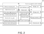
- FIG. 2 is a configuration block diagram of the surveying apparatus 100
- FIG. 3 is a schematic view describing configurations of a distance-measuring unit 10 and an image projecting unit 70.
- the projection image 6 can include various modifications (for example, projection images 6a to 6c) as described later, and the projection image 6 is representatively described in a common description.
- the surveying apparatus 100 is a so-called motor-driven total station.
- the surveying apparatus 100 is installed at a known point via a tripod 2 and a leveling base 3 mounted on the tripod 2.
- the surveying apparatus 100 includes a base portion 4a to be removably mounted on the leveling base 3, a bracket portion 4b provided horizontally rotatably 360° around an axis H-H on the base portion 4a, and a telescope 4c provided vertically rotatably about an axis V-V in a recessed portion 5 of the bracket portion 4b.
- the surveying apparatus 100 includes the distance-measuring unit 10, an angle-measuring unit 20, a rotation driving unit 30, a control arithmetic unit 40, a display unit 50, a storage unit 60, the image projecting unit 70, and an operation unit 80.
- the distance-measuring unit 10 is disposed inside the telescope 4c, and generally includes, as illustrated in FIG. 3 , a light emitting element 11, a distance-measuring optical system 12, and a light receiving element 13.
- the distance-measuring unit 10 emits distance-measuring light L from the light emitting element 11 through the distance-measuring optical system 12 to irradiate a measuring object through a double-sided mirror 14, and receives reflected light La from the measuring object by the light receiving element 13 through the double-sided mirror 14 and the distance-measuring optical system 12. Based on a phase difference between a light emission signal and a light reception signal acquired by the distance-measuring unit 10, a distance to the irradiation point can be measured.
- the distance-measuring unit 10 is not limited to this, and may be provided with a publicly known configuration included with a light wave distance meter.
- the distance-measuring unit 10 can further include an eyepiece lens, etc., for enabling a user to perform collimation toward a collimation direction.
- the double-sided mirror 14 is between the distance-measuring unit 10 and the image projecting unit 70, and is fixed to the telescope 4c and rotates about the axis V-V integrally with the telescope 4c.
- the double-sided mirror 14 reflects the distance-measuring light L by one surface and reflects projection light M by the other surface so that optical axes of the distance-measuring light L and the projection light M advance toward directions opposite to each other on the same axis.
- the angle-measuring unit 20 includes a horizontal angle detector 21 and a vertical angle detector 22.
- the horizontal angle detector 21 and the vertical angle detector 22 are, for example, rotary encoders.
- the rotation driving unit 30 includes a horizontal rotation driving unit 31 and a vertical rotation driving unit 32.
- the horizontal rotation driving unit 31 is a motor, and is provided on the base portion 4a and rotates the bracket portion 4b horizontally about the axis H-H.
- the horizontal angle detector 21 is provided on a rotary shaft portion of the horizontal rotation driving unit 31, and can detect a horizontal angle of the bracket portion 4b, that is, the horizontal angle detector 21 can detect a horizontal angle of the collimation direction of the telescope 4c.
- the vertical rotation driving unit 32 is a motor, and is provided on the bracket portion 4b and rotates the telescope 4c vertically about the axis V-V.
- the vertical angle detector 22 is provided on a rotary shaft portion of the vertical rotation driving unit 32, and can detect a vertical angle of the collimation direction of the telescope 4c. Detection signals acquired by the distance-measuring unit 10 and the angle-measuring unit 20 are input into the control arithmetic unit 40.
- the display unit 50 is, for example, a liquid crystal display, an organic EL (Electro Luminescence) display, etc.
- the display unit 50 displays survey results and operation screens, etc., according to control of the control arithmetic unit 40.
- the storage unit 60 is a recording medium that stores, describes, saves, and transmits information in a computer-processable form, and stores various programs that fulfill functions of the control arithmetic unit 40 including functions of functional units described later.
- the storage unit 60 stores measurement data acquired by a survey unit 41 and a projection image 6 generated by a projection image generating unit 42.
- a magnetic disc such as a hard disc drive, a magneto optical disc such as a CD (Compact Disc) and a DVD (Digital Versatile Disc), or a semiconductor memory such as a flash memory and a RAM (Random Access Memory) can be adopted.
- the image projecting unit 70 is a projector device generally including a light irradiating device 71, a display element 72, and a projector lens 73 as illustrated in FIG. 3 .
- the light irradiating device 71 is a device including a light source (not illustrated) and configured to irradiate visible light as projection light M toward a display element 72 through a projecting optical system 74 and the double-sided mirror 14.
- a color-separation type is adopted as an example.
- the light source a semiconductor light emitting element such as an LED (Light Emitting Diode) or a laser diode, or a lamp (halogen lamp, xenon lamp, etc.) can be adopted.
- the display element 72 is a DMD (Digital Micromirror Device), a transmissive liquid crystal display panel, or a reflective liquid crystal display panel, having a plurality of pixels two-dimensionally arrayed.
- DMD Digital Micromirror Device
- pixels of the display element 72 are movable micromirrors
- pixels of the display element 72 are liquid crystal shutter elements.
- the light irradiating device 71 When the light irradiating device 71 is a color-separation type, the light irradiating device 71 has a white light source and a color separator, etc., and white light emitted from the white light source is separated into red (R), green (G), and blue (B) that are the three primary colors of light by the color separator.
- the display element 72 is prepared for each color, and the display elements 72 are irradiated with lights in the multiple colors, and lights transmitted through or reflected by the respective display elements 72 are synthesized.
- the light irradiating device 71 without being limited to the color-separation type, a time-division type, and an independent light source type which are adopted in a general projector device can be adopted. In each case, a display element 72 corresponding to the light irradiating device 71 can be adopted.
- the projector lens 73 projects a display image formed by the display element 72 onto a measuring object.
- the projector lens 73 is capable of adjusting focusing and adjusting a focal length.
- the projector lens 73 is driven by a lens driving unit (not illustrated).
- the lens driving unit performs zooming and focusing by driving lenses constituting the projector lens 73. Zooming and focusing may be performed by a user's operation, or may be performed by control of a projection control unit 43 described later.
- the image projecting unit 70 is provided inside the telescope 4c as well as the distance-measuring unit 10.
- the distance-measuring unit 10 and the image projecting unit 70 are configured so that, for example, an optical axis of the distance-measuring light L of the distance-measuring unit 10 and an optical axis of the projection light M from the projecting unit are opposed to each other on a common axis.
- the common axis is an axis on the collimation axis of the telescope 4c passing through an instrument center O.
- the instrument center O is an intersection between the axis H-H and the axis V-V, and is a point that becomes an origin of three-dimensional coordinates to be acquired by the surveying apparatus 100.
- the image projecting unit 70 When the image projecting unit 70 is driven by the projection control unit 43, the light irradiating device 51 is driven, and projection light M is emitted and enters the display element 72.
- the display element 72 forms an image as a projection image 6.
- the image as the projection image 6 is projected onto a surface of the measuring object as a projection target.
- the positional relationship between the distance-measuring unit 10 and the image projecting unit 70 does not necessarily have to be arranged so that they are opposed to each other on a common axis. What is required is that the positional relationship between the distance-measuring unit 10 and the image projecting unit 70 is known, and the projection image 6 and the measurement data can be converted into data in the same coordinate space.
- the operation unit 80 is realized by any of, or a combination of any of all kinds of devices capable of receiving an input from a user and transmitting information related to the input to the control arithmetic unit 40.
- the operation unit 80 includes hardware input means such as buttons, software input means displayed on the display unit 50 such as a touch panel display, and input means such as a remote controller.
- the control arithmetic unit 40 executes functions and/or methods realized by codes or instructions included in various programs stored in the storage unit 60.
- the control arithmetic unit 40 may include, for example, a CPU (Central Processing Unit), a GPU (Graphics Processing Unit) microprocessor, and an ASIC (Application Specific Integrated Circuit), etc., and realize various processings disclosed in this specification by a logic circuit and a dedicated circuit formed in an integrated circuit, etc.
- the control arithmetic unit 40 includes, as functional units, the survey unit 41, the projection image generating unit 42, and the projection control unit 43.
- the survey unit 41 performs a survey by the surveying apparatus 100 and calculates coordinates of the irradiation point of the distance-measuring light L, that is, the measurement point. Specifically, by controlling the rotation driving unit 30, the telescope 4c collimates the measuring object, and by the distance-measuring unit 10 and the angle-measuring unit 20, a horizontal angle, a vertical angle, and a distance between the surveying apparatus 100 and (the irradiation point on) the measuring object are detected. In addition, the survey unit 41 calculates coordinates of the measurement point with respect to an instrument center O set as a center based on the acquired horizontal angle, vertical angle, and distance. The coordinates of the measurement point calculated by the survey unit 41 are stored as measurement data in the storage unit 60.
- the projection image generating unit 42 calculates a three-dimensional shape of the measuring object based on the measurement data acquired by the survey unit 41 and is stored in the storage unit 60. Next, this three-dimensional shape data is read by three-dimensional computer graphics, and distortion correction for projecting the measurement data as a visually confirmable image on a screen corresponding to the surface shape of the measuring object, is performed to generate the projection image 6.
- an image displaying measurement points P 1 to P 9 and measurement points P 11 to P 16 as circular points is illustrated.
- a distortion correction method for example, spline warp correction and pin warp correction, etc., can be applied. Shapes and colors of the measurement points in the generated image may be changeable.
- the projection control unit 43 drives the light irradiating device 71 to emit projection light M, and causes the projection light M to enter the display element 72.
- the projection control unit 43 performs a control to form an image as the projection image 6 by the projection light M reflected by or transmitted through the display element 72. Accordingly, the image as the projection image 6 is projected onto the surface of the measuring object as a projection target through the projector lens 73.
- the projection control unit 43 directs the image projecting unit 70 toward the projection direction (measuring object) by controlling the rotation driving unit 30.
- the projection control unit 43 performs zooming and focusing of the projection image 6 by driving the lens driving unit.
- the lens driving unit is controlled based on the measurement data so that a portion where the measurement points are linearly arranged and dense is set as a focal position.
- a user can designate a plane as a reference, and the lens driving unit is controlled so that the focal position is set on the plane.
- FIG. 4 is a flowchart of operation of the surveying apparatus 100 in use. The on-site work illustrated in FIG. 1 is described.
- the surveying apparatus 100 is installed at a known point.
- the survey unit 41 collimates a measuring object S1 by driving the distance-measuring unit 10 and the angle-measuring unit 20, and measures a distance and an angle to a measurement point on the measuring object S1.
- Step S102 the survey unit 41 calculates three-dimensional coordinates of the measurement point from the results of the distance and angle measurements.
- the acquired three-dimensional coordinates of the measurement point are stored as measurement data in the storage unit 60.
- Step S103 the survey unit 41 displays a screen for confirming whether to continue the measurement on the display unit 50, and according to a user's selection, continuation (Yes) or end (No) of the measurement is selected.
- Step S101 When the measurement is continued (Yes), the processing returns to Step S101, and the survey unit 41 repeats Steps S101 to S103 to measure another measurement point.
- Step S104 the projection image generating unit 42 displays a screen for confirming whether to project the image on the display unit 50, and according to a user's selection, it is selected to project the image (Yes) or not to project the image (No).
- Step S105 the projection image generating unit 42 generates the projection image 6 based on the measurement data stored in the storage unit 60.
- Step S106 the projection control unit 43 directs the image projecting unit 70 (projector lens 73) toward the projection direction, that is, the measuring object S1 direction in a real space by driving the rotation driving unit 30.
- Steps S105 and S106 do not necessarily have to be performed in this order. That is, when a user desires to project measurement data of a specific portion (for example, the measuring object S1 in FIG. 1 ) in a real space, it is also possible that after image projection is selected in Step S104, in Step S106, the projector lens 73 is directed toward the measuring object S1 by driving the rotation driving unit 30. In this case, by executing Step S105 next, the projection image 6 is generated based on the measurement data of the portion of the measuring object S1 in the image projecting unit 70.
- Step S107 the projection control unit 43 controls the image projecting unit 70 to project the projection image 6 onto the measuring object S1 ( FIG. 1 ).
- the projection image 6 displays the measurement points P 1 to P 9 and P 11 to P 16 as circular points arranged at even intervals vertically and horizontally on a surface of the three-dimensional structure S1.
- a measurement point P 10 not displayed is a point that has not been measured for some reason.
- the measuring object S1 is simply schematically illustrated, and its shape is not particularly restricted.
- Step S108 the projection control unit 43 stands by while confirming whether the end of projection is instructed, and when the end of projection is instructed (No), ends the processing.
- Steps S101 to S103 and the image projection in Steps S104 to S108 do not necessarily have to be performed as a series of operations, and may be performed as separate operations.
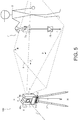
- FIG. 5 is a view illustrating another usage state of the surveying apparatus 100.
- FIG. 5 illustrates a situation where staking points P 1 to P 4 are being set.
- a user U uses a remote catcher 7 including a fan beam transmitter 7a that transmits a fan beam and a prism 7b.
- the surveying apparatus 100 further includes a fan beam detector and an automatic tracking unit that automatically tracks the prism although not illustrated, and acquires three-dimensional coordinates of a staking point by measuring a distance and an angle to the prism vertically held on the staking point.
- the surveying apparatus 100 can also be used for confirming the staking points after staking.
- the surveying apparatus 100 is provided with the image projecting unit 70 so as to project measurement data onto a measuring object in a real space, so that measurement results can be confirmed on-site without being carried back to an office and converted into display data.
- the surveying apparatus 100 is provided with the image projecting unit 70 so as to project measurement data onto a measuring object in a real space, so that measurement results can be confirmed on-site without being carried back to an office and converted into display data.
- the surveying apparatus 100 is provided with the image projecting unit 70 so as to project measurement data onto a measuring object in a real space, so that measurement results can be confirmed on-site without being carried back to an office and converted into display data.
- the image projecting unit 70 so as to project measurement data onto a measuring object in a real space
- the optical axis of the image projecting unit 70 can be matched with the optical axis of the distance-measuring unit 10 only by rotating the telescope 4c by 180° in the vertical direction, so that complicated arithmetic processing is not required when generating the projection image in the projection image generating unit 42, and the processing time can be shortened.
- FIG. 6 is an external general view illustrating a state where a surveying apparatus 200 according to a second embodiment is projecting a projection image 6a.
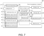
- FIG. 7 is a configuration block diagram of the surveying apparatus 200
- FIG. 8 is a schematic view describing configurations of the distance-measuring unit 10 and the image projecting unit 70 disposed in a light projecting unit 204c.
- the surveying apparatus 200 is a so-called three-dimensional laser scanner.
- the surveying apparatus 200 and the surveying apparatus 100 have a common configuration except for the following respects.
- the surveying apparatus 100 includes the telescope 4c that rotates about the axis V-V in the recessed portion 5 of the bracket 4b, and on the other hand, the surveying apparatus 200 includes the light projecting unit 204c in a recessed portion 205 of a bracket portion 204b.
- a turning mirror 90 is provided between the distance-measuring unit 210 and the image projecting unit 70 in FIG. 8 .
- the turning mirror 90 is a double-sided mirror, and like the double-sided mirror 14, the turning mirror 90 is configured so that emitting optical axes of the distance-measuring unit 210 and the image projecting unit 70 advance toward directions opposite to each other on the same axis.
- the turning mirror 90 is connected to the vertical rotation driving unit 32 so that, by performing scanning around the axis V-V by setting the instrument center O as a center, scanning in the vertical direction with the distance-measuring light L can be performed.
- a light emitting element 211 emits a pulse laser light (pulsed light).
- the surveying apparatus 200 is configured to be capable of acquiring point cloud data of the entire circumference by scanning the entire circumference with the distance-measuring light L in the horizontal direction and the vertical direction.
- the image projecting unit 70 When the image projecting unit 70 is driven, the turning mirror 90 does not rotate, and the turning mirror 90 and the image projecting unit 70 are fixed.
- the image projecting unit 70 may be configured to rotate integrally with the turning mirror 90 so as not to obstruct the optical path of the distance-measuring light L during scanning with the distance-measuring light L.
- the surveying apparatus 200 includes a point cloud data acquiring unit 241 and a projection image generating unit 242 in a control arithmetic unit 240.
- the point cloud data acquiring unit 241 scans a measurement range (up to 360°) with the distance-measuring light L by driving the distance-measuring unit 210, the angle-measuring unit 20, and the rotation driving unit 30, acquires three-dimensional point cloud data of the measurement range, and stores the three-dimensional point cloud data in the storage unit 60.
- the projection image generating unit 242 Based on the point cloud data stored in the storage unit 60, the projection image generating unit 242 generates a projection image 6a in the same manner as in the projection image generating unit 42.
- the projection image 6a illustrated in FIG. 6 displays the respective points of point cloud data as circular points. Even in this case where the surveying apparatus 200 is a 3D laser scanner, the same effect as that of the first embodiment can be obtained in which measurement results can be confirmed on-site without being carried back to an office and converted into display data.
- omission of a point cloud is found in a lower right portion in a front view of the measuring object S2. This may occur due to temporary presence of an obstacle such as a vehicle between the measuring object S2 and the surveying apparatus 200 at the time of the measurement. In this way, a user can intuitively recognize a point cloud data acquisition omitted portion (acquiring situation).
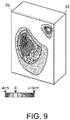
- FIG. 9 illustrates a projection image 6b according to an example, generated by the projection image generating unit 242.
- irregularities on the surface of a measuring object S3 are displayed in a recognizable manner.
- differences in distance from the surface among the respective points of point cloud data are displayed like a heat map.
- the projection image generating unit 242 calculates a three-dimensional shape of the measuring object S3 based on the measurement data (point cloud data) stored in the storage unit 60. Then, this three-dimensional shape data is read by three-dimensional computer graphics, and the surface of the measuring object is obtained.
- predetermined ranges for example, ranges of 0 to 2 cm, 2 to 4 cm ..., etc.
- FIG. 9 around the center of the surface of the measuring object S3, a portion protruding by 10 cm is illustrated.
- the same effect can be obtained even when the projection image generating unit 242 is configured to generate an image that displays irregularities on the surface of the measuring object S3 in a recognizable manner like a so-called depth map by using different colors for each of predetermined ranges corresponding to distances from the instrument center to the respective points.
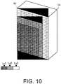
- FIG. 10 illustrates a projection image 6c according to another example, generated by the projection image generating unit 242.
- a surface of a measuring object S4 is divided into grids (meshes) at predetermined intervals, and the respective squares are displayed in colors different according to levels of point cloud density in the square regions.
- the projection image generating unit 242 calculates a three-dimensional shape of the measuring object S4. Then, this three-dimensional shape data is read by three-dimensional computer graphics, and the surface of the measuring object S4 is obtained.
- the surface of the measuring object is divided into grids at predetermined intervals, and from the measurement data, point cloud densities in the respective squares are calculated and classified into 3 levels including level 1 (Lv. 1) set to 200 points or more/m 3 , level 2 (Lv. 2) set to 100 to 200 points/m 3 , and level 3 (Lv. 3) set to less than 100 points/m 3 , and the projection image 6c displayed in colors different according to the levels of point cloud density in the squares is generated.
- level 1 Lv. 1
- level 2 Lv. 2
- level 3 Lv. 3
- this projection image 6c By projecting this projection image 6c, a user can visually and intuitively recognize a situation such as which portion meets required density in the point cloud data of the measuring object S4.
- Modifications of the projection image are not limited to these, and for example, the levels of point cloud density may be displayed like a heat map as with the projection image 6b. Alternatively, irregularities from the surface may be displayed in meshes.
- FIG. 11 is a configuration block diagram of a surveying apparatus 300 according to a third embodiment
- FIG. 12 is an external general view illustrating a state where the surveying apparatus 300 is projecting a projection image 6d, and illustrates a situation of measurement of the same site as in FIG. 1 .
- the surveying apparatus 300 is a total station having substantially the same configuration as that of the surveying apparatus 100, but is different in that a storage unit 360 has design data 61 of the measuring object S1, and the control arithmetic unit 340 includes a projection image generating unit 342 in place of the projection image generating unit 42.
- the projection image generating unit 34 is configured to calculate a difference between the design data 61 and the measurement data when generating the projection image 6d, and generate an image displaying the difference from the measurement data in a recognizable manner.
- the deviating portion may be conspicuously displayed by being changed in color or shape as illustrated in FIG. 12 .
- the same modification can be applied to the surveying apparatus of the second embodiment, and can be applied in combination with the above-described modification of the projection image.
- the surveying apparatus according to the embodiments described above may be further modified as follows.
Landscapes
- Engineering & Computer Science (AREA)
- Physics & Mathematics (AREA)
- General Physics & Mathematics (AREA)
- Radar, Positioning & Navigation (AREA)
- Remote Sensing (AREA)
- Computer Networks & Wireless Communication (AREA)
- Electromagnetism (AREA)
- Length Measuring Devices By Optical Means (AREA)
- Measurement Of Optical Distance (AREA)
Applications Claiming Priority (1)
| Application Number | Priority Date | Filing Date | Title |
|---|---|---|---|
| JP2020118605A JP7543010B2 (ja) | 2020-07-09 | 2020-07-09 | 測量装置 |
Publications (2)
| Publication Number | Publication Date |
|---|---|
| EP3936820A1 true EP3936820A1 (fr) | 2022-01-12 |
| EP3936820B1 EP3936820B1 (fr) | 2025-06-18 |
Family
ID=76764863
Family Applications (1)
| Application Number | Title | Priority Date | Filing Date |
|---|---|---|---|
| EP21183363.7A Active EP3936820B1 (fr) | 2020-07-09 | 2021-07-02 | Système d'arpentage |
Country Status (3)
| Country | Link |
|---|---|
| US (1) | US20220011107A1 (fr) |
| EP (1) | EP3936820B1 (fr) |
| JP (1) | JP7543010B2 (fr) |
Cited By (1)
| Publication number | Priority date | Publication date | Assignee | Title |
|---|---|---|---|---|
| CN119022882A (zh) * | 2024-09-05 | 2024-11-26 | 北京城建勘测设计研究院有限责任公司 | 一种工程建设基坑沉降监测设备 |
Families Citing this family (4)
| Publication number | Priority date | Publication date | Assignee | Title |
|---|---|---|---|---|
| US11435445B2 (en) * | 2019-12-20 | 2022-09-06 | Trimble, Inc. | Laser receiver and target with lighted indicators |
| US11435182B2 (en) * | 2019-12-20 | 2022-09-06 | Trimble, Inc. | Laser receiver and target with lighted indicators |
| JP7845747B2 (ja) * | 2022-03-08 | 2026-04-14 | 株式会社トプコン | 測量支援システム、情報表示端末、測量支援方法、及び測量支援プログラム |
| CN116659377B (zh) * | 2023-05-06 | 2026-04-07 | 上海建工集团股份有限公司 | 基于测量精度和稳定性的三维扫描最大测距确定方法 |
Citations (7)
| Publication number | Priority date | Publication date | Assignee | Title |
|---|---|---|---|---|
| US20120057174A1 (en) * | 2010-01-20 | 2012-03-08 | Faro Technologies, Inc. | Laser scanner or laser tracker having a projector |
| US20160377722A1 (en) * | 2015-06-23 | 2016-12-29 | Mezmeriz, Inc. | Portable panoramic laser mapping and/or projection system |
| EP3226029A1 (fr) * | 2016-03-30 | 2017-10-04 | Hexagon Technology Center GmbH | Scanner à laser avec projecteur référencé |
| JP2018045587A (ja) | 2016-09-16 | 2018-03-22 | 株式会社トプコン | 画像処理装置、画像処理方法、画像処理用プログラム |
| JP2018048868A (ja) | 2016-09-21 | 2018-03-29 | 株式会社トプコン | スキャナ装置および測量装置 |
| US20190064328A1 (en) * | 2017-08-30 | 2019-02-28 | Hexagon Technology Center Gmbh | Surveying instrument for scanning an object and for projection of information |
| JP2019148946A (ja) * | 2018-02-27 | 2019-09-05 | 前田建設工業株式会社 | 施工工程管理システム及び施工工程管理方法 |
Family Cites Families (10)
| Publication number | Priority date | Publication date | Assignee | Title |
|---|---|---|---|---|
| US8537376B2 (en) * | 2011-04-15 | 2013-09-17 | Faro Technologies, Inc. | Enhanced position detector in laser tracker |
| JP6301678B2 (ja) * | 2014-02-24 | 2018-03-28 | アジア航測株式会社 | スタンドアロン型点群データ表示システム、サーバ/クライアント型の点群データ表示システム及び点群データ表示プログラム |
| EP3091333B1 (fr) * | 2015-05-08 | 2019-07-03 | Leica Geosystems AG | Procédé de balayage et système d'arpentage disposant d'une fonctionnalité de balayage |
| JP2017058141A (ja) | 2015-09-14 | 2017-03-23 | 株式会社トプコン | 平坦度測定システム及び平坦度測定方法 |
| US10989542B2 (en) * | 2016-03-11 | 2021-04-27 | Kaarta, Inc. | Aligning measured signal data with slam localization data and uses thereof |
| JP6884016B2 (ja) | 2017-03-22 | 2021-06-09 | 清水建設株式会社 | トンネル掘削管理処理方法及びトンネル掘削管理処理装置 |
| EP3460394B1 (fr) * | 2017-09-26 | 2020-06-03 | Hexagon Technology Center GmbH | Instrument d'arpentage, système de réalité augmentée (ra) et procédé de référencement d'un dispositif de ra relatif à un système de référence |
| JP7232437B2 (ja) | 2018-02-19 | 2023-03-03 | 国立大学法人 東京大学 | 作業車両の表示システム及び生成方法 |
| EP3534240A1 (fr) * | 2018-03-01 | 2019-09-04 | CMORE Automotive GmbH | Procédé et dispositif d'annotation de données |
| SE543979C2 (en) * | 2019-09-20 | 2021-10-12 | Metso Outotec Finland Oy | Mining Equipment Inspection System, Mining Equipment Inspection Method, and Mining Equipment Inspection Device |
-
2020
- 2020-07-09 JP JP2020118605A patent/JP7543010B2/ja active Active
-
2021
- 2021-06-30 US US17/363,136 patent/US20220011107A1/en active Pending
- 2021-07-02 EP EP21183363.7A patent/EP3936820B1/fr active Active
Patent Citations (7)
| Publication number | Priority date | Publication date | Assignee | Title |
|---|---|---|---|---|
| US20120057174A1 (en) * | 2010-01-20 | 2012-03-08 | Faro Technologies, Inc. | Laser scanner or laser tracker having a projector |
| US20160377722A1 (en) * | 2015-06-23 | 2016-12-29 | Mezmeriz, Inc. | Portable panoramic laser mapping and/or projection system |
| EP3226029A1 (fr) * | 2016-03-30 | 2017-10-04 | Hexagon Technology Center GmbH | Scanner à laser avec projecteur référencé |
| JP2018045587A (ja) | 2016-09-16 | 2018-03-22 | 株式会社トプコン | 画像処理装置、画像処理方法、画像処理用プログラム |
| JP2018048868A (ja) | 2016-09-21 | 2018-03-29 | 株式会社トプコン | スキャナ装置および測量装置 |
| US20190064328A1 (en) * | 2017-08-30 | 2019-02-28 | Hexagon Technology Center Gmbh | Surveying instrument for scanning an object and for projection of information |
| JP2019148946A (ja) * | 2018-02-27 | 2019-09-05 | 前田建設工業株式会社 | 施工工程管理システム及び施工工程管理方法 |
Cited By (1)
| Publication number | Priority date | Publication date | Assignee | Title |
|---|---|---|---|---|
| CN119022882A (zh) * | 2024-09-05 | 2024-11-26 | 北京城建勘测设计研究院有限责任公司 | 一种工程建设基坑沉降监测设备 |
Also Published As
| Publication number | Publication date |
|---|---|
| EP3936820B1 (fr) | 2025-06-18 |
| US20220011107A1 (en) | 2022-01-13 |
| JP7543010B2 (ja) | 2024-09-02 |
| JP2022015633A (ja) | 2022-01-21 |
Similar Documents
| Publication | Publication Date | Title |
|---|---|---|
| EP3936820B1 (fr) | Système d'arpentage | |
| JP6963936B2 (ja) | 測量システム | |
| US10921430B2 (en) | Surveying system | |
| EP2506035B1 (fr) | Scanner laser et procédé de détection d'objet mobile | |
| US8355118B2 (en) | Laser scanner, laser scanner measuring system, calibration method for laser scanner measuring system and target for calibration | |
| EP2503284B1 (fr) | Système de surveillance avec appareil de surveillance, balise et émetteur-récepteur mobile sans fil | |
| US10488519B2 (en) | Polygon mirror, fan beam output device, and survey system | |
| US8638446B2 (en) | Laser scanner or laser tracker having a projector | |
| JP6899737B2 (ja) | 測量システム | |
| US20200105043A1 (en) | Point cloud data display system | |
| EP3401639A1 (fr) | Système de relevé | |
| JP2003214852A (ja) | 位置測定装置及びそれに使用する回転レーザ装置 | |
| JP2000221033A (ja) | 回転レーザ装置及びその対象反射体 | |
| JP7314447B2 (ja) | スキャナシステム及びスキャン方法 | |
| JP2017058141A (ja) | 平坦度測定システム及び平坦度測定方法 | |
| JP7138525B2 (ja) | 測量装置及び測量装置システム | |
| US20200081266A1 (en) | Surveying Instrument | |
| JP6680628B2 (ja) | レーザスキャナ | |
| JP2023078427A (ja) | ターゲットユニットおよびターゲットユニットシステム | |
| US20190339075A1 (en) | Surveying Instrument | |
| JP7187235B2 (ja) | 測量システム、測量機、および測量方法 | |
| JP7289252B2 (ja) | スキャナシステムおよびスキャン方法 | |
| JP2023152591A (ja) | 点群情報生成システム、点群情報生成システムの制御方法及び点群情報生成システムの制御プログラム | |
| JP6913422B2 (ja) | 測量システム | |
| JP2017058142A (ja) | 投影装置及び投影システム |
Legal Events
| Date | Code | Title | Description |
|---|---|---|---|
| PUAI | Public reference made under article 153(3) epc to a published international application that has entered the european phase |
Free format text: ORIGINAL CODE: 0009012 |
|
| STAA | Information on the status of an ep patent application or granted ep patent |
Free format text: STATUS: THE APPLICATION HAS BEEN PUBLISHED |
|
| AK | Designated contracting states |
Kind code of ref document: A1 Designated state(s): AL AT BE BG CH CY CZ DE DK EE ES FI FR GB GR HR HU IE IS IT LI LT LU LV MC MK MT NL NO PL PT RO RS SE SI SK SM TR |
|
| B565 | Issuance of search results under rule 164(2) epc |
Effective date: 20211115 |
|
| STAA | Information on the status of an ep patent application or granted ep patent |
Free format text: STATUS: REQUEST FOR EXAMINATION WAS MADE |
|
| 17P | Request for examination filed |
Effective date: 20220712 |
|
| RBV | Designated contracting states (corrected) |
Designated state(s): AL AT BE BG CH CY CZ DE DK EE ES FI FR GB GR HR HU IE IS IT LI LT LU LV MC MK MT NL NO PL PT RO RS SE SI SK SM TR |
|
| STAA | Information on the status of an ep patent application or granted ep patent |
Free format text: STATUS: EXAMINATION IS IN PROGRESS |
|
| 17Q | First examination report despatched |
Effective date: 20240214 |
|
| GRAP | Despatch of communication of intention to grant a patent |
Free format text: ORIGINAL CODE: EPIDOSNIGR1 |
|
| STAA | Information on the status of an ep patent application or granted ep patent |
Free format text: STATUS: GRANT OF PATENT IS INTENDED |
|
| INTG | Intention to grant announced |
Effective date: 20240816 |
|
| GRAJ | Information related to disapproval of communication of intention to grant by the applicant or resumption of examination proceedings by the epo deleted |
Free format text: ORIGINAL CODE: EPIDOSDIGR1 |
|
| STAA | Information on the status of an ep patent application or granted ep patent |
Free format text: STATUS: EXAMINATION IS IN PROGRESS |
|
| GRAP | Despatch of communication of intention to grant a patent |
Free format text: ORIGINAL CODE: EPIDOSNIGR1 |
|
| STAA | Information on the status of an ep patent application or granted ep patent |
Free format text: STATUS: GRANT OF PATENT IS INTENDED |
|
| INTC | Intention to grant announced (deleted) | ||
| INTG | Intention to grant announced |
Effective date: 20250117 |
|
| GRAS | Grant fee paid |
Free format text: ORIGINAL CODE: EPIDOSNIGR3 |
|
| GRAA | (expected) grant |
Free format text: ORIGINAL CODE: 0009210 |
|
| STAA | Information on the status of an ep patent application or granted ep patent |
Free format text: STATUS: THE PATENT HAS BEEN GRANTED |
|
| AK | Designated contracting states |
Kind code of ref document: B1 Designated state(s): AL AT BE BG CH CY CZ DE DK EE ES FI FR GB GR HR HU IE IS IT LI LT LU LV MC MK MT NL NO PL PT RO RS SE SI SK SM TR |
|
| REG | Reference to a national code |
Ref country code: GB Ref legal event code: FG4D |
|
| REG | Reference to a national code |
Ref country code: CH Ref legal event code: EP |
|
| REG | Reference to a national code |
Ref country code: DE Ref legal event code: R096 Ref document number: 602021032342 Country of ref document: DE |
|
| REG | Reference to a national code |
Ref country code: CH Ref legal event code: EP |
|
| REG | Reference to a national code |
Ref country code: IE Ref legal event code: FG4D |
|
| PG25 | Lapsed in a contracting state [announced via postgrant information from national office to epo] |
Ref country code: FI Free format text: LAPSE BECAUSE OF FAILURE TO SUBMIT A TRANSLATION OF THE DESCRIPTION OR TO PAY THE FEE WITHIN THE PRESCRIBED TIME-LIMIT Effective date: 20250618 |
|
| PGFP | Annual fee paid to national office [announced via postgrant information from national office to epo] |
Ref country code: DE Payment date: 20250708 Year of fee payment: 5 |
|
| REG | Reference to a national code |
Ref country code: LT Ref legal event code: MG9D |
|
| PG25 | Lapsed in a contracting state [announced via postgrant information from national office to epo] |
Ref country code: NO Free format text: LAPSE BECAUSE OF FAILURE TO SUBMIT A TRANSLATION OF THE DESCRIPTION OR TO PAY THE FEE WITHIN THE PRESCRIBED TIME-LIMIT Effective date: 20250918 Ref country code: GR Free format text: LAPSE BECAUSE OF FAILURE TO SUBMIT A TRANSLATION OF THE DESCRIPTION OR TO PAY THE FEE WITHIN THE PRESCRIBED TIME-LIMIT Effective date: 20250919 |
|
| PG25 | Lapsed in a contracting state [announced via postgrant information from national office to epo] |
Ref country code: BG Free format text: LAPSE BECAUSE OF FAILURE TO SUBMIT A TRANSLATION OF THE DESCRIPTION OR TO PAY THE FEE WITHIN THE PRESCRIBED TIME-LIMIT Effective date: 20250618 |
|
| PG25 | Lapsed in a contracting state [announced via postgrant information from national office to epo] |
Ref country code: HR Free format text: LAPSE BECAUSE OF FAILURE TO SUBMIT A TRANSLATION OF THE DESCRIPTION OR TO PAY THE FEE WITHIN THE PRESCRIBED TIME-LIMIT Effective date: 20250618 |
|
| PGFP | Annual fee paid to national office [announced via postgrant information from national office to epo] |
Ref country code: AT Payment date: 20251020 Year of fee payment: 5 |
|
| PGFP | Annual fee paid to national office [announced via postgrant information from national office to epo] |
Ref country code: CH Payment date: 20250801 Year of fee payment: 5 |
|
| PG25 | Lapsed in a contracting state [announced via postgrant information from national office to epo] |
Ref country code: RS Free format text: LAPSE BECAUSE OF FAILURE TO SUBMIT A TRANSLATION OF THE DESCRIPTION OR TO PAY THE FEE WITHIN THE PRESCRIBED TIME-LIMIT Effective date: 20250918 |
|
| REG | Reference to a national code |
Ref country code: NL Ref legal event code: MP Effective date: 20250618 |
|
| PG25 | Lapsed in a contracting state [announced via postgrant information from national office to epo] |
Ref country code: LV Free format text: LAPSE BECAUSE OF FAILURE TO SUBMIT A TRANSLATION OF THE DESCRIPTION OR TO PAY THE FEE WITHIN THE PRESCRIBED TIME-LIMIT Effective date: 20250618 |
|
| PG25 | Lapsed in a contracting state [announced via postgrant information from national office to epo] |
Ref country code: NL Free format text: LAPSE BECAUSE OF FAILURE TO SUBMIT A TRANSLATION OF THE DESCRIPTION OR TO PAY THE FEE WITHIN THE PRESCRIBED TIME-LIMIT Effective date: 20250618 |
|
| PG25 | Lapsed in a contracting state [announced via postgrant information from national office to epo] |
Ref country code: PT Free format text: LAPSE BECAUSE OF FAILURE TO SUBMIT A TRANSLATION OF THE DESCRIPTION OR TO PAY THE FEE WITHIN THE PRESCRIBED TIME-LIMIT Effective date: 20251020 |
|
| REG | Reference to a national code |
Ref country code: AT Ref legal event code: MK05 Ref document number: 1804533 Country of ref document: AT Kind code of ref document: T Effective date: 20250618 |
|
| PG25 | Lapsed in a contracting state [announced via postgrant information from national office to epo] |
Ref country code: IS Free format text: LAPSE BECAUSE OF FAILURE TO SUBMIT A TRANSLATION OF THE DESCRIPTION OR TO PAY THE FEE WITHIN THE PRESCRIBED TIME-LIMIT Effective date: 20251018 |
|
| PG25 | Lapsed in a contracting state [announced via postgrant information from national office to epo] |
Ref country code: SM Free format text: LAPSE BECAUSE OF FAILURE TO SUBMIT A TRANSLATION OF THE DESCRIPTION OR TO PAY THE FEE WITHIN THE PRESCRIBED TIME-LIMIT Effective date: 20250618 Ref country code: AT Free format text: LAPSE BECAUSE OF FAILURE TO SUBMIT A TRANSLATION OF THE DESCRIPTION OR TO PAY THE FEE WITHIN THE PRESCRIBED TIME-LIMIT Effective date: 20250618 |
|
| PG25 | Lapsed in a contracting state [announced via postgrant information from national office to epo] |
Ref country code: CZ Free format text: LAPSE BECAUSE OF FAILURE TO SUBMIT A TRANSLATION OF THE DESCRIPTION OR TO PAY THE FEE WITHIN THE PRESCRIBED TIME-LIMIT Effective date: 20250618 |
|
| PG25 | Lapsed in a contracting state [announced via postgrant information from national office to epo] |
Ref country code: PL Free format text: LAPSE BECAUSE OF FAILURE TO SUBMIT A TRANSLATION OF THE DESCRIPTION OR TO PAY THE FEE WITHIN THE PRESCRIBED TIME-LIMIT Effective date: 20250618 |
|
| PG25 | Lapsed in a contracting state [announced via postgrant information from national office to epo] |
Ref country code: EE Free format text: LAPSE BECAUSE OF FAILURE TO SUBMIT A TRANSLATION OF THE DESCRIPTION OR TO PAY THE FEE WITHIN THE PRESCRIBED TIME-LIMIT Effective date: 20250618 |
|
| PG25 | Lapsed in a contracting state [announced via postgrant information from national office to epo] |
Ref country code: SK Free format text: LAPSE BECAUSE OF FAILURE TO SUBMIT A TRANSLATION OF THE DESCRIPTION OR TO PAY THE FEE WITHIN THE PRESCRIBED TIME-LIMIT Effective date: 20250618 Ref country code: RO Free format text: LAPSE BECAUSE OF FAILURE TO SUBMIT A TRANSLATION OF THE DESCRIPTION OR TO PAY THE FEE WITHIN THE PRESCRIBED TIME-LIMIT Effective date: 20250618 |
|
| PG25 | Lapsed in a contracting state [announced via postgrant information from national office to epo] |
Ref country code: ES Free format text: LAPSE BECAUSE OF FAILURE TO SUBMIT A TRANSLATION OF THE DESCRIPTION OR TO PAY THE FEE WITHIN THE PRESCRIBED TIME-LIMIT Effective date: 20250618 |
|
| PG25 | Lapsed in a contracting state [announced via postgrant information from national office to epo] |
Ref country code: LU Free format text: LAPSE BECAUSE OF NON-PAYMENT OF DUE FEES Effective date: 20250702 |
|
| REG | Reference to a national code |
Ref country code: DE Ref legal event code: R097 Ref document number: 602021032342 Country of ref document: DE |
|
| REG | Reference to a national code |
Ref country code: BE Ref legal event code: MM Effective date: 20250731 |
|
| PG25 | Lapsed in a contracting state [announced via postgrant information from national office to epo] |
Ref country code: MC Free format text: LAPSE BECAUSE OF FAILURE TO SUBMIT A TRANSLATION OF THE DESCRIPTION OR TO PAY THE FEE WITHIN THE PRESCRIBED TIME-LIMIT Effective date: 20250618 |
|
| PG25 | Lapsed in a contracting state [announced via postgrant information from national office to epo] |
Ref country code: DK Free format text: LAPSE BECAUSE OF FAILURE TO SUBMIT A TRANSLATION OF THE DESCRIPTION OR TO PAY THE FEE WITHIN THE PRESCRIBED TIME-LIMIT Effective date: 20250618 |
|
| PG25 | Lapsed in a contracting state [announced via postgrant information from national office to epo] |
Ref country code: IT Free format text: LAPSE BECAUSE OF FAILURE TO SUBMIT A TRANSLATION OF THE DESCRIPTION OR TO PAY THE FEE WITHIN THE PRESCRIBED TIME-LIMIT Effective date: 20250618 Ref country code: BE Free format text: LAPSE BECAUSE OF NON-PAYMENT OF DUE FEES Effective date: 20250731 |
|
| PLBE | No opposition filed within time limit |
Free format text: ORIGINAL CODE: 0009261 |
|
| STAA | Information on the status of an ep patent application or granted ep patent |
Free format text: STATUS: NO OPPOSITION FILED WITHIN TIME LIMIT |
|
| REG | Reference to a national code |
Ref country code: CH Ref legal event code: L10 Free format text: ST27 STATUS EVENT CODE: U-0-0-L10-L00 (AS PROVIDED BY THE NATIONAL OFFICE) Effective date: 20260430 |