EP3226251A1 - Particle beam irradiation equipment - Google Patents
Particle beam irradiation equipment Download PDFInfo
- Publication number
- EP3226251A1 EP3226251A1 EP14907083.1A EP14907083A EP3226251A1 EP 3226251 A1 EP3226251 A1 EP 3226251A1 EP 14907083 A EP14907083 A EP 14907083A EP 3226251 A1 EP3226251 A1 EP 3226251A1
- Authority
- EP
- European Patent Office
- Prior art keywords
- electromagnet
- position information
- beam irradiation
- particle beam
- positions
- Prior art date
- Legal status (The legal status is an assumption and is not a legal conclusion. Google has not performed a legal analysis and makes no representation as to the accuracy of the status listed.)
- Withdrawn
Links
Images




Classifications
-
- H—ELECTRICITY
- H01—ELECTRIC ELEMENTS
- H01F—MAGNETS; INDUCTANCES; TRANSFORMERS; SELECTION OF MATERIALS FOR THEIR MAGNETIC PROPERTIES
- H01F7/00—Magnets
- H01F7/06—Electromagnets; Actuators including electromagnets
- H01F7/20—Electromagnets; Actuators including electromagnets without armatures
-
- H—ELECTRICITY
- H05—ELECTRIC TECHNIQUES NOT OTHERWISE PROVIDED FOR
- H05H—PLASMA TECHNIQUE; PRODUCTION OF ACCELERATED ELECTRICALLY-CHARGED PARTICLES OR OF NEUTRONS; PRODUCTION OR ACCELERATION OF NEUTRAL MOLECULAR OR ATOMIC BEAMS
- H05H7/00—Details of devices of the types covered by groups H05H9/00, H05H11/00, H05H13/00
- H05H7/04—Magnet systems, e.g. undulators, wigglers; Energisation thereof
-
- A—HUMAN NECESSITIES
- A61—MEDICAL OR VETERINARY SCIENCE; HYGIENE
- A61N—ELECTROTHERAPY; MAGNETOTHERAPY; RADIATION THERAPY; ULTRASOUND THERAPY
- A61N5/00—Radiation therapy
- A61N5/10—X-ray therapy; Gamma-ray therapy; Particle-irradiation therapy
-
- A—HUMAN NECESSITIES
- A61—MEDICAL OR VETERINARY SCIENCE; HYGIENE
- A61N—ELECTROTHERAPY; MAGNETOTHERAPY; RADIATION THERAPY; ULTRASOUND THERAPY
- A61N5/00—Radiation therapy
- A61N5/10—X-ray therapy; Gamma-ray therapy; Particle-irradiation therapy
- A61N5/1048—Monitoring, verifying, controlling systems and methods
- A61N5/1075—Monitoring, verifying, controlling systems and methods for testing, calibrating, or quality assurance of the radiation treatment apparatus
-
- G—PHYSICS
- G21—NUCLEAR PHYSICS; NUCLEAR ENGINEERING
- G21K—HANDLING OF PARTICLES OR IONISING RADIATION NOT OTHERWISE PROVIDED FOR; IRRADIATION DEVICES; GAMMA RAY OR X-RAY MICROSCOPES
- G21K1/00—Arrangements for handling particles or ionising radiation, e.g. focusing or moderating
- G21K1/08—Deviation, concentration or focusing of the beam by electric or magnetic means
- G21K1/093—Deviation, concentration or focusing of the beam by electric or magnetic means by magnetic means
-
- G—PHYSICS
- G21—NUCLEAR PHYSICS; NUCLEAR ENGINEERING
- G21K—HANDLING OF PARTICLES OR IONISING RADIATION NOT OTHERWISE PROVIDED FOR; IRRADIATION DEVICES; GAMMA RAY OR X-RAY MICROSCOPES
- G21K5/00—Irradiation devices
- G21K5/04—Irradiation devices with beam-forming means
-
- H—ELECTRICITY
- H05—ELECTRIC TECHNIQUES NOT OTHERWISE PROVIDED FOR
- H05H—PLASMA TECHNIQUE; PRODUCTION OF ACCELERATED ELECTRICALLY-CHARGED PARTICLES OR OF NEUTRONS; PRODUCTION OR ACCELERATION OF NEUTRAL MOLECULAR OR ATOMIC BEAMS
- H05H13/00—Magnetic resonance accelerators; Cyclotrons
- H05H13/04—Synchrotrons
-
- A—HUMAN NECESSITIES
- A61—MEDICAL OR VETERINARY SCIENCE; HYGIENE
- A61N—ELECTROTHERAPY; MAGNETOTHERAPY; RADIATION THERAPY; ULTRASOUND THERAPY
- A61N5/00—Radiation therapy
- A61N5/10—X-ray therapy; Gamma-ray therapy; Particle-irradiation therapy
- A61N2005/1085—X-ray therapy; Gamma-ray therapy; Particle-irradiation therapy characterised by the type of particles applied to the patient
- A61N2005/1087—Ions; Protons
-
- A—HUMAN NECESSITIES
- A61—MEDICAL OR VETERINARY SCIENCE; HYGIENE
- A61N—ELECTROTHERAPY; MAGNETOTHERAPY; RADIATION THERAPY; ULTRASOUND THERAPY
- A61N5/00—Radiation therapy
- A61N5/10—X-ray therapy; Gamma-ray therapy; Particle-irradiation therapy
- A61N5/1042—X-ray therapy; Gamma-ray therapy; Particle-irradiation therapy with spatial modulation of the radiation beam within the treatment head
- A61N5/1043—Scanning the radiation beam, e.g. spot scanning or raster scanning
-
- H—ELECTRICITY
- H05—ELECTRIC TECHNIQUES NOT OTHERWISE PROVIDED FOR
- H05H—PLASMA TECHNIQUE; PRODUCTION OF ACCELERATED ELECTRICALLY-CHARGED PARTICLES OR OF NEUTRONS; PRODUCTION OR ACCELERATION OF NEUTRAL MOLECULAR OR ATOMIC BEAMS
- H05H2245/00—Applications of plasma devices
- H05H2245/30—Medical applications
-
- H—ELECTRICITY
- H05—ELECTRIC TECHNIQUES NOT OTHERWISE PROVIDED FOR
- H05H—PLASMA TECHNIQUE; PRODUCTION OF ACCELERATED ELECTRICALLY-CHARGED PARTICLES OR OF NEUTRONS; PRODUCTION OR ACCELERATION OF NEUTRAL MOLECULAR OR ATOMIC BEAMS
- H05H2277/00—Applications of particle accelerators
- H05H2277/10—Medical devices
Definitions
- the reference position information of the first electromagnet provided on the upstream side of the high-energy-beam irradiation-system line and the second electromagnet provided on the downstream side thereof is prestored in the storage unit, and then the positions and attitudes of the first electromagnet and the second electromagnet are adjusted at the time of their realignment, on the basis of the reference position information stored in the storage unit.
- the positions and attitudes of the electromagnets even if the building deforms due to seasonal variation in outside air, crustal movement or the like.
- the storage unit 3 is configured with a storage medium such as a hard disk, a removable disk, a memory or the like, in which, at the time of installation of the particle beam irradiation system (at the time of first alignment), position information about positions, attitudes and the like, of the electromagnets 1 measured by the cameras 10 is stored as the reference positions.
- a storage medium such as a hard disk, a removable disk, a memory or the like
- Step S53 When the position information at the time of the realignment of the electromagnets 1 (1A, 1B) is acquired in Step S53, the control unit 2 then takes out the position information of the reference positions from the storage unit 3, to thereby calculate the displacement amounts by comparing the position information at the time of the realignment of the electromagnets 1 (1A, 1B) with the position information of the reference positions (Step S54).
- the control unit 2 outputs control information such as an actuation amount or the like, to any one of the actuators of the electromagnets 1 (1A, 1B) for the vertical direction (11A-1, 11A-2, 11A-3, 11B-1, 11B-2, 11B-3) and the actuators thereof for the horizontal directions (11A-4, 11A-5, 11B-4, 11B-5), to thereby instruct it to cause actuation, so that the positions, attitudes and the like, of the electromagnets 1 (1A, 1B) are adjusted.
- control information such as an actuation amount or the like
- the relative position information is acquired using the plurality of cameras 10 (10-1, 10-2, ⁇ , 10-n), even if the main electromagnet placed on the upstream side of the HEBT system line and the electromagnet placed on the downstream side thereof are distantly positioned, for example, they are placed on different floors in the building, it is possible to precisely adjust the electromagnets while keeping their relative positions, attitudes and the like. This makes it possible to achieve highly-precise beam irradiation.
- FIG. 6 is a block diagram showing a configuration of particle beam irradiation equipment 200 according to Embodiment 2 of the invention.
- FIG. 7 is an external view of an electromagnet for particle beam irradiation system, which is provided with the particle beam irradiation equipment 200.
- the control unit 2 causes the storage unit 3 to prestore the position information about the measured positions, attitudes and the like, of the electromagnets 1 (1A, 1B), and at the time of the realignment, the control unit calculates, using the deformation simulator 4, deformation amounts of the building, the apparatuses and the like, to thereby acquire position information of the electromagnets 1 (1A, 1B) at the time of the realignment, based on the position information as the reference positions stored in the storage unit 3.
- Configuration and operations other than the above, of the particle beam irradiation equipment 200 are similar to those in the configuration and the operations of the particle beam irradiation equipment 100 of Embodiment 1 shown in FIG. 1 and FIG. 5 , so that the same reference numerals are given to the same parts and description thereof is omitted here.
- the control unit 2 causes the storage unit 3, at the time of the first alignment, to prestore the position information about the measured positions, attitudes and the like, of the electromagnets 1 (1A, 1B), and then acquires the displacement amounts, based on the position information as the reference positions stored in the storage unit 3, and from the position information of the electromagnets 1 (1A, 1B) acquired by the deformation simulator 4 at the time of the realignment.
- the storage unit 3 at the time of the first alignment, to prestore the position information about the measured positions, attitudes and the like, of the electromagnets 1 (1A, 1B), and then acquires the displacement amounts, based on the position information as the reference positions stored in the storage unit 3, and from the position information of the electromagnets 1 (1A, 1B) acquired by the deformation simulator 4 at the time of the realignment.
- the apparatuses and the like are calculated using the deformation simulator 4, even if the main electromagnet placed on the upstream side of the HEBT system line and the electromagnet placed on the downstream side thereof are distantly positioned, for example, they are placed on different floors in the building, it is possible to precisely adjust the electromagnets while keeping their relative positions, attitudes and the like. This makes it possible to achieve highly-precise beam irradiation.
- the position information at the time of the realignment of the electromagnets 1 (1A, 1B) is acquired by the deformation simulator 4, at the time of the realignment; however, this is not limitative.
- the displacement amounts of the electromagnets 1 (1A, 1B) may be estimated at the time of the first alignment, based on the position information that is the reference positions stored in the storage unit 3. This also allows to recognize the time when the realignment becomes necessary, thus making it possible to create a plan for realignment beforehand.
- FIG. 8 is a block diagram showing a configuration of particle beam irradiation equipment 300 according to Embodiment 3 of the invention.
- FIG. 9 is an external view of an electromagnet 1 A for particle beam irradiation system, which is provided with the particle beam irradiation equipment 300.
- the transmitted position information from the GPS transmitters 13 (13A, 13B) is received by the GPS receiver 5 placed at an original point in the building (for example, at a center point of the synchrotron).
- the position of the GPS receiver 5 viewed from the electromagnets 1 (1A, 1B) having the respective sets of three GPS transmitters 13 (13A, 13B) is determined.
- back calculation is applied using the position of the GPS receiver 5 as the original point, it is possible to calculate the relative positions, attitudes and the like, of the electromagnet 1A and the electromagnet 1B at the time the GPS receiver 5 is regarded as a reference.
- the control unit 2 causes the storage unit 3, at the time of the first alignment, to store as position information of the reference positions, the position information of the electromagnets 1 (1A, 1B) acquired from the position information transmitted from the GPS transmitters 13 (13A, 13B), using the position of the GPS receiver 5 as the original point, and then acquires the displacement amounts, based on the position information of the reference positions stored in the storage unit 3, and from the position information of the electromagnets 1 (1A, 1B) acquired from the position information transmitted from the GPS transmitters 13 (13A, 13B), at the time of the realignment, using the position of the GPS receiver 5 as the original point.
- the control unit 2 causes the storage unit 3, at the time of the first alignment, to store as position information of the reference positions, the position information of the electromagnets 1 (1A, 1B) acquired from the position information transmitted from the GPS transmitters 13 (13A, 13B), using the position of the GPS receiver 5 as the original point, and then acquires the displacement amounts, based on the position information of the reference positions stored
- Embodiments 1 to 3 there is described that the positions, attitudes and the like, of the electromagnet 1A and the electromagnet 1B are both adjusted; however, this is not limitative. When either one of the electromagnet 1A and the electromagnet 1B is adjusted so that their relative positions and attitudes are kept, this also makes it possible to achieve highly-precise beam irradiation.
- the alignment of the electromagnets when they are placed on different floors in the building, it is general that the electromagnet nearer to the ground is not moved but the electromagnet on the upper floor, which is easily influenced by expansion/contraction of the building, is solely adjusted so that their relative positions are unchanged.
Landscapes
- Engineering & Computer Science (AREA)
- Physics & Mathematics (AREA)
- Health & Medical Sciences (AREA)
- Biomedical Technology (AREA)
- Spectroscopy & Molecular Physics (AREA)
- Plasma & Fusion (AREA)
- Electromagnetism (AREA)
- Public Health (AREA)
- General Health & Medical Sciences (AREA)
- Pathology (AREA)
- Nuclear Medicine, Radiotherapy & Molecular Imaging (AREA)
- Radiology & Medical Imaging (AREA)
- Life Sciences & Earth Sciences (AREA)
- Animal Behavior & Ethology (AREA)
- Veterinary Medicine (AREA)
- General Engineering & Computer Science (AREA)
- High Energy & Nuclear Physics (AREA)
- Optics & Photonics (AREA)
- Power Engineering (AREA)
- Particle Accelerators (AREA)
- Radiation-Therapy Devices (AREA)
Abstract
Description
- The present invention relates to particle beam irradiation equipment which can precisely control the position, attitude and the like, of an electromagnet used in a particle beam irradiation system.
- In conventional particle beam irradiation systems, it is general that an accelerator such as a synchrotron or the like and a treatment room are placed on the same plane. In recent years, in association with enlargement of the particle beam irradiation systems, deformation of the building thereof occurs due to seasonal variation in outside air temperature or due to crustal movement such as ground depression or the like, resulting in wrong alignment and thus in failure of the radiated beam to meet a prescribed performance.
- In order to deal therewith, in the use of the particle beam irradiation system, there has arisen a need to change its operation parameters for every season, or to periodically execute re-adjustment of the positions, attitudes and the like, of the electromagnets and the like.
- As a method of establishing alignment at the time of installation of the particle beam irradiation system, there is disclosed a method in which alignment is established after a displacement amount from a preset position, which is given as a reference point in the building or on the apparatus, is calculated (see, for example,
Patent Document 1 and Patent Document 2). - Meanwhile, in the case where the particle beam irradiation facility is constructed on a narrow ground adjacent to a hospital or the like, a structure in which the accelerator and the treatment room are arranged in vertical relation therebetween, or something like that, is likely to be employed (see, for example, Patent Document 3).
-
- Patent Document 1:
- Japanese Patent Application Laid-Open
JP 2006-344 466 A FIG. 2 ) - Patent Document 2:
- Japanese Patent Application Laid-Open
JP 2006-302 818 A FIG. 2 ) - Patent Document 3:
- Japanese Patent Application Laid-Open
JP 2011-182 987 A FIG. 1 ) - In a case where the accelerator and the treatment room are arranged in vertical relation therebetween, there is a problem that the structure of the building becomes complex, resulting in large deformation of the building due to temperature variation between seasons, or the like. In particular, in the case where the accelerator or a beam-transport-system apparatus is arranged above the treatment room, there is a problem that the deformation is more remarkable than otherwise, because a floor on which such an apparatus is arranged, is placed apart from a building foundation part strengthened by foundation improvement or by piling, so that an interspace by the treatment room or the like, exists under the floor on which the apparatus is placed.
- Further, with respect to the beam-transport-system apparatus, because the electromagnets for controlling transportation of the beam are placed respectively on different floors, there is a problem that it is difficult to precisely control the relative positions and attitudes of the electromagnets.
- This invention has been made to solve the problems as described above, and an object thereof is to provide particle beam therapy equipment which makes highly-precise beam irradiation possible, not only when the accelerator or the like and the treatment room in the particle beam irradiation system are placed on the same plane, but also when they are arranged in vertical relation therebetween.
- The particle beam irradiation equipment of the invention comprises:
- a first electromagnet provided on an upstream side of a high-energy-beam irradiation-system line;
- a second electromagnet provided on a downstream side of the high-energy-beam irradiation-system line;
- a position information acquisition unit that acquires position information of the first electromagnet and the second electromagnet;
- a storage unit in which the position information of the first electromagnet and the second electromagnet at the time of their first alignment, is prestored as reference position information;
- an adjustment mechanism that adjusts positions and attitudes of the first electromagnet and the second electromagnet; and
- a control unit that calculates, based on the reference position information stored in the storage unit, and from position information of the first electromagnet and the second electromagnet acquired at the time of their realignment by the position information acquisition unit, displacement amounts of positions and attitudes of the first electromagnet and the second electromagnet occurring from the time of the first alignment to the time of the realignment, and controls/adjusts using the adjustment mechanism, the positions and attitudes of the first electromagnet and the second electromagnet according to the displacement amounts.
- According to this invention, the reference position information of the first electromagnet provided on the upstream side of the high-energy-beam irradiation-system line and the second electromagnet provided on the downstream side thereof, is prestored in the storage unit, and then the positions and attitudes of the first electromagnet and the second electromagnet are adjusted at the time of their realignment, on the basis of the reference position information stored in the storage unit. Thus, it is possible to easily adjust the positions and attitudes of the electromagnets even if the building deforms due to seasonal variation in outside air, crustal movement or the like.
-
-
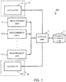
FIG. 1 is a block diagram showing a configuration of particle beam irradiation equipment according toEmbodiment 1 of the invention. -
FIG. 2 is a perspective view showing an external appearance of the particle beam irradiation equipment according toEmbodiment 1 of the invention. -
FIG. 3 is a diagram illustrating an adjusting method by the particle beam irradiation equipment according toEmbodiment 1 of the invention. -
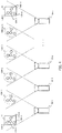
FIG. 4 is a diagram illustrating how to acquire position information by the particle beam irradiation equipment according toEmbodiment 1 of the invention. -
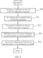
FIG. 5 is a flowchart illustrating a method of controlling a position and an attitude by the particle beam irradiation equipment according toEmbodiment 1 of the invention. -
FIG. 6 is a block diagram showing a configuration of particle beam irradiation equipment according toEmbodiment 2 of the invention. -
FIG. 7 is a perspective view showing an external appearance of the particle beam irradiation equipment according toEmbodiment 2 of the invention. -
FIG. 8 is a block diagram showing a configuration of particle beam irradiation equipment according toEmbodiment 3 of the invention. -
FIG. 9 is a perspective view showing an external appearance of the particle beam irradiation equipment according toEmbodiment 3 of the invention. -
FIG. 1 is a block diagram showing a configuration of particlebeam irradiation equipment 100 according toEmbodiment 1 of the invention.FIG. 2 is an external view of anelectromagnet 1A for particle beam irradiation system, which is provided with the particlebeam irradiation equipment 100. - As shown in
FIG. 1 andFIG. 2 , the particlebeam irradiation equipment 100 is configured with: a plurality of cameras 10 (10-1, 10-2, ···, 10-n [n denotes an integer]) serving as a measurement unit which is a position information acquisition unit for acquiring position information about positions, attitudes and the like, of electromagnets 1 (1A, 1B); astorage unit 3 in which the position information of the electromagnets 1 (1A, 1B) at the time of installation of the particle beam irradiation system is stored as reference positions; acontrol unit 2 for acquiring measured positions of the electromagnets 1 (1A, 1B) measured by thecameras 10 and the reference positions of the electromagnets 1 (1A, 1B) stored in thestorage unit 3, to thereby output control information; and actuators 11 (11A, 11B) serving as an adjustment mechanism for adjusting the positions and attitudes of theelectromagnets 1 according to the control information from thecontrol unit 2. - In order to measure the relative positions and attitudes of the
first electromagnet 1A and thesecond electromagnet 1B that are placed at two positions apart from each other, stereo cameras are used as thecameras 10. However, in the case of the particle beam irradiation system in which the accelerator and the irradiation room are placed on different floors in the building, theelectromagnet 1A and theelectromagnet 1B that are main electromagnets at two places in the line of a high-energy-beam irradiation system (referred also to as High-Energy Beam Transport (hereinafter, HEBT) System), go beyond the view of one of thecamera 10. For this reason, ingenuity is required in the measurement using thecameras 10. - In
Embodiment 1 of the invention, in order to solve the aforementioned problem on the view of the camera, the following method is used. Here, it is assumed that the measurement is made on themain electromagnet 1 A placed on the upstream side of the HEBT system line and the othermain electromagnet 1B placed on the downstream side of the HEBT system line. Using one camera 10-1, the positions oftargets 12A (12A-1, 12A-2, 12A-3, 12A-4) formed on theelectromagnet 1A are measured. Then, using another camera 10-2, the positions oftargets 12B (12B-1, 12B-2, 12B-3, 12B-4) formed on theelectromagnet 1B are measured. However, if nothing is then done, what has just been done is that the position and attitude of theelectromagnet 1A have been expressed on a coordinate system (x, y, z) that the camera 10-1 has, while the position and attitude of theelectromagnet 1B have been expressed on a coordinate system (X, Y, Z) that the camera 10-2 has. The relative relationship in position and attitude between theelectromagnet 1A and theelectromagnet 1B are unknown. - In this regard, as shown in
FIG. 3 , if an overlapping portion exists between the views of the camera 10-A and the camera 10-B2 and at least four number (or three number, in a two-dimensional case) of coordinate-conversion purpose targets 12M (12M-a, 12M-b, 12M-c, 12M-d) can be placed at different positions within the overlapping portion, it is possible to determine a coordinate conversion formula for converting the coordinate system on the camera 10-A into the coordinate system on the camera 10-B, from information of coordinates on the camera 10-A about the fourtargets 12M (12M-a, 12M-b, 12M-c, 12M-d) and information of coordinates on the camera 10-B about the targets. - Specifically, description is given as follows.
- The coordinate conversion formula for converting the coordinate system (x, y, z) on the camera 10-A into the coordinate system (X, Y, Z) on the camera 10-B has a structure of a following formula.
[Mathematical Expression 1]
- In order to finally determine the coordinate conversion formula (1), it is required to calculate the twelve number of unknown parameters T11, ··, T33, O1, ··, O3.
- Applying the formula (1) to the respective coordinate-
conversion purpose targets 12M (12M-a, 12M-b, 12M-c, 12M-d) comes down to the issue of solving the simultaneous equations comprising four formulae. When the four formulae are bundled together using matrix expression, they can be expressed as follows.
[Mathematical Expression 2]
- Further, in the case of seeking to get coordinate conversion using four or more number of the targets in consideration of a measurement error or the like, it is conceivable to use least-square method for seeking.
[Mathematical Expression 3]
- It is noted that the superscript T is indicative of a transposed matrix.
- In the case where no overlapping portion exists between the views of the camera 10-A and the camera 10-B, as shown in
FIG. 4 , it is conceivable to additionally prepare another plurality of cameras, and to link the camera 10-1 to the camera 10-n to each other in a row so that overlapping portions exist each in a small degree between their respective views. In each location where the views of the adjacent cameras are overlapped, each set of coordinate-conversion purpose targets 12M-1, 12M-2, ···, or 12M-(n-1) each comprising four targets, is placed and then subjected to measurement. This finally makes it possible to determine, using coordinate conversion of the coordinate systems of the respective cameras, the coordinate conversion formula from the coordinate system (xl, y1, z1) on the camera 10-1 to the coordinate system (xn, yn, zn) on the camera 10-n. - In this manner, when the coordinate systems are made matched to each other using the plurality of cameras 10 (10-1, 10-2, ···. 10-n), even if the
main electromagnet 1A placed on the upstream side of the HEBT system line and the othermain electromagnet 1B placed on the downstream side of the HEBT system line are positioned on different floors in the building, it is possible to measure the relative positions and attitudes of theelectromagnet 1A and theelectromagnet 1B. - The
storage unit 3 is configured with a storage medium such as a hard disk, a removable disk, a memory or the like, in which, at the time of installation of the particle beam irradiation system (at the time of first alignment), position information about positions, attitudes and the like, of theelectromagnets 1 measured by thecameras 10 is stored as the reference positions. - The
control unit 2 acquires, using thecameras 10, the position information about the positions, attitudes and the like, of the electromagnets 1 (1A, 1B) at their first alignment, and stores it in thestorage unit 3 as reference positions. Further, thecontrol unit 2 acquires, using thecameras 10, position information about positions, attitudes and the like, of the electromagnets 1 (1A, 1B) at their realignment, and compares it with the position information of theelectromagnets 1 as the reference positions taken out from thestorage unit 3, to thereby calculate displacement amounts or the like, due to deformation of the building or the like, and then adjusts the positions and attitudes of theelectromagnets 1 by controlling the actuators 11 according to the control information, such as the calculated displacement amounts or the like. Thecontrol unit 2 can be implemented using a general-purpose computer system or the like (for example, a personal computer). - The actuators 11 are mounted on pedestals 14 (14A-1, 14A-2, 14B-1, 14B-2) of the
electromagnets 1. As shown inFIG. 2 , theactuators 11A (or 11B) comprise actuators (11A(B)-1, 11A(B)-2, 11A(B)-3) for a vertical direction and actuators (11A(B)-4, 11A(B)-5) for two horizontal directions, and are thus mounted corresponding to total three directions (six degrees of freedom). The actuators 11 (11 A, 11B) are actuated according to the control information from thecontrol unit 2. - Next, operations of the particle
beam irradiation equipment 100 according toEmbodiment 1 of the invention will be described usingFIG. 5. FIG. 5 is a flowchart illustrating the operations of the particlebeam irradiation equipment 100. - As shown in
FIG. 5 , at the time of the first alignment, firstly, thecontrol unit 2 of the particlebeam irradiation equipment 100 measures, using the cameras 10 (10-1, 10-2, ···, 10-n), positions of the fourtargets 12A-1, 12A-2, 12A-3, 12A-4 placed on each of the electromagnets 1 (1A, 1B). From data of coordinates of thus-obtained positions, the positions, attitudes and the like, of the electromagnets 1 (1A, 1B) are calculated, so that the position information at the time of the first alignment is acquired (Step S51). - Subsequently, the
control unit 2 causes thestorage unit 3 to store the position information of the electromagnets 1 (1A, 1B) at the time of the first alignment that is acquired in Step S51, as position information of the reference positions of the electromagnets 1 (1A, 1B) (Step S52). At this time, even if themain electromagnet 1A that is placed on the upstream side and theelectromagnet 1B that is placed on the downstream side are distantly positioned, the position information is given as relative reference positions, when the plurality of cameras 10-1, 10-2, ···, 10-n is used; the coordinate-conversion purpose targets 12M-1, 12M-2, ···, 12M-(n-1) are placed in each location where the views of the adjacent cameras are overlapped and are then subjected to measurement; and the position information is determined after the coordinate axes of theelectromagnet 1A and theelectromagnet 1B are matched to each other. - Then, when alignment is performed again because of deformation of the building due to seasonal variation in outside air temperature, crustal movement or the like, the
control unit 2 again measures, using the cameras 10 (10-1, 10-2, ···, 10-n), positions of the fourtargets 12A-1, 12A-2, 12A-3, 12A-4 placed on each of the electromagnets 1 (1A, 1B). From data of coordinates of thus-obtained positions, the positions, attitudes and the like, of the electromagnets 1 (1A, 1B) are calculated, so that the position information at the time of the realignment is acquired (Step S53). - When the position information at the time of the realignment of the electromagnets 1 (1A, 1B) is acquired in Step S53, the
control unit 2 then takes out the position information of the reference positions from thestorage unit 3, to thereby calculate the displacement amounts by comparing the position information at the time of the realignment of the electromagnets 1 (1A, 1B) with the position information of the reference positions (Step S54). - At this time, even if the
electromagnet 1A and theelectromagnet 1B are distantly positioned, when, like in the case of the first alignment, the plurality of cameras 10-1, 10-2, ···, 10-n is used to measure the coordinate- conversion purpose targets 12M-1, 12M-2, ···, 12M-(n-1) placed in each location where the views of the adjacent cameras are overlapped, and the relative position information is given after the coordinate axes of theelectromagnet 1A and theelectromagnet 1B are matched to each other, it is possible to highly precisely find the displacement amounts, because the relative positional relationship of theelectromagnet 1 A and theelectromagnet 1B is determined on a comparison basis with the reference positions. - Lastly, based on the thus-obtained displacement amounts of the electromagnets 1 (1 A, 1 B), the
control unit 2 outputs control information such as an actuation amount or the like, to any one of the actuators of the electromagnets 1 (1A, 1B) for the vertical direction (11A-1, 11A-2, 11A-3, 11B-1, 11B-2, 11B-3) and the actuators thereof for the horizontal directions (11A-4, 11A-5, 11B-4, 11B-5), to thereby instruct it to cause actuation, so that the positions, attitudes and the like, of the electromagnets 1 (1A, 1B) are adjusted. - As described above, in the particle
beam irradiation equipment 100 according toEmbodiment 1 of the invention, thecontrol unit 2 causes thestorage unit 3, at the time of the first alignment, to store the position information of the electromagnets 1 (1A, 1B) acquired by the cameras 10 (10-1, 10-2, ···, 10-n) as position information of the reference positions, and then acquires the displacement amounts, based on the position information of the reference positions stored in thestorage unit 3, from the position information of the electromagnets 1 (1A, 1B) acquired by the cameras 10 (10-1, 10-2, ···, 10-n) at the time of the realignment. Thus, it is possible to easily adjust the positions, attitudes and the like, of the electromagnets even if the building deforms due to seasonal variation in outside air, crustal movement or the like. - In addition, because the relative position information is acquired using the plurality of cameras 10 (10-1, 10-2, ···, 10-n), even if the main electromagnet placed on the upstream side of the HEBT system line and the electromagnet placed on the downstream side thereof are distantly positioned, for example, they are placed on different floors in the building, it is possible to precisely adjust the electromagnets while keeping their relative positions, attitudes and the like. This makes it possible to achieve highly-precise beam irradiation.
- In
Embodiment 1, a case has been shown in which the position information at the time of the realignment is acquired by thecameras 10, whereas inEmbodiment 2, a case will be shown in which that information is acquired by simulation. -
FIG. 6 is a block diagram showing a configuration of particlebeam irradiation equipment 200 according toEmbodiment 2 of the invention.FIG. 7 is an external view of an electromagnet for particle beam irradiation system, which is provided with the particlebeam irradiation equipment 200. - As shown in
FIG. 6 andFIG. 7 , the particlebeam irradiation equipment 200 includes adeformation simulator 4 serving as an analysis unit, in place of the cameras 10 (10-1, 10-2, ···, 10-n) serving as a measurement unit inEmbodiment 1. Thedeformation simulator 4 carries out deformation simulation using, for example, a finite element analysis in which the building, the apparatuses and the like, are all modelized. At the time of the first alignment, thecontrol unit 2 causes thestorage unit 3 to prestore the position information about the measured positions, attitudes and the like, of the electromagnets 1 (1A, 1B), and at the time of the realignment, the control unit calculates, using thedeformation simulator 4, deformation amounts of the building, the apparatuses and the like, to thereby acquire position information of the electromagnets 1 (1A, 1B) at the time of the realignment, based on the position information as the reference positions stored in thestorage unit 3. - In this manner, when all the deformation amounts of the building, the apparatuses and the like, at the time of the realignment, are calculated using the
deformation simulator 4 and the position information is acquired therefrom, even if themain electromagnet 1A placed on the upstream side of the HEBT system line and the othermain electromagnet 1B placed on the downstream side of the HEBT system line are positioned on different floors in the building, it is possible to easily recognize the relative positions, attitudes and the like, of theelectromagnet 1A and theelectromagnet 1B, and it is possible to highly precisely find the displacement amounts because the relative positional relationship of theelectromagnet 1A and theelectromagnet 1B is determined on a comparison basis with the reference positions. - Configuration and operations other than the above, of the particle
beam irradiation equipment 200, are similar to those in the configuration and the operations of the particlebeam irradiation equipment 100 ofEmbodiment 1 shown inFIG. 1 andFIG. 5 , so that the same reference numerals are given to the same parts and description thereof is omitted here. - As described above, in the particle
beam irradiation equipment 200 according toEmbodiment 2 of the invention, thecontrol unit 2 causes thestorage unit 3, at the time of the first alignment, to prestore the position information about the measured positions, attitudes and the like, of the electromagnets 1 (1A, 1B), and then acquires the displacement amounts, based on the position information as the reference positions stored in thestorage unit 3, and from the position information of the electromagnets 1 (1A, 1B) acquired by thedeformation simulator 4 at the time of the realignment. Thus, it is possible to easily adjust the positions, attitudes and the like, of the electromagnets even if the building deforms due to seasonal variation in outside air, crustal movement or the like. - In addition, because all the deformation amounts of the building, the apparatuses and the like are calculated using the
deformation simulator 4, even if the main electromagnet placed on the upstream side of the HEBT system line and the electromagnet placed on the downstream side thereof are distantly positioned, for example, they are placed on different floors in the building, it is possible to precisely adjust the electromagnets while keeping their relative positions, attitudes and the like. This makes it possible to achieve highly-precise beam irradiation. - It is noted that, in
Embodiment 2, the position information at the time of the realignment of the electromagnets 1 (1A, 1B) is acquired by thedeformation simulator 4, at the time of the realignment; however, this is not limitative. The displacement amounts of the electromagnets 1 (1A, 1B) may be estimated at the time of the first alignment, based on the position information that is the reference positions stored in thestorage unit 3. This also allows to recognize the time when the realignment becomes necessary, thus making it possible to create a plan for realignment beforehand. - In
Embodiment 1, a case has been shown in which the position information at the time of the realignment is acquired by thecameras 10, whereas inEmbodiment 3, a case will be shown in which that information is acquired by a GPS receiver. -
FIG. 8 is a block diagram showing a configuration of particlebeam irradiation equipment 300 according toEmbodiment 3 of the invention.FIG. 9 is an external view of anelectromagnet 1 A for particle beam irradiation system, which is provided with the particlebeam irradiation equipment 300. - As shown in
FIG. 8 andFIG. 9 , the particlebeam irradiation equipment 200 includes aGPS receiver 5 serving as a receiving unit, in place of the cameras 10 (10-1, 10-2, ···, 10-n) serving as a measurement unit inEmbodiment 1. Further, the equipment includes CPS transmitters 13 (13A, 13B) each serving as a transmission unit, in place of the targets 12 (12A, 12B) inEmbodiment 1. Three number of the GPS receivers 13 (13A, 13B) are provided on each of the electromagnets 1 (1A, 1B), and each determine its own position through observation of the position or the like by themultiple GPS satellites 50, and then transmit the position information thereof. The transmitted position information from the GPS transmitters 13 (13A, 13B) is received by theGPS receiver 5 placed at an original point in the building (for example, at a center point of the synchrotron). When the position information transmitted from the respective sets of three GPS transmitters 13 (13A, 13B) is received, the position of theGPS receiver 5 viewed from the electromagnets 1 (1A, 1B) having the respective sets of three GPS transmitters 13 (13A, 13B) is determined. When back calculation is applied using the position of theGPS receiver 5 as the original point, it is possible to calculate the relative positions, attitudes and the like, of theelectromagnet 1A and theelectromagnet 1B at the time theGPS receiver 5 is regarded as a reference. - At the time of the first alignment, the
control unit 2 receives, using theGPS receiver 5, the position information transmitted from the GPS transmitters 13 (13A, 13B), and calculates the positions, attitudes and the like, of the electromagnets 1 (1A, 1B) using the position of theGPS receiver 5 as the original point, to thereby acquire the position information at the time of the first alignment. Also at the time of the realignment, likewise, the control unit receives, using theGPS receiver 5, the position information transmitted from the GPS transmitters 13 (13A, 13B), and calculates the positions, attitudes and the like, of the electromagnets 1 (1A, 1B) using the position of theGPS receiver 5 as the original point, to thereby acquire the position information at the time of the realignment. - In this manner, when the position information of the electromagnets 1 (1A, 1B) is acquired, using the position of the
GPS receiver 5 as the original point, from the position information transmitted from the GPS transmitters 13 (13A, 13B), even if themain electromagnet 1A placed on the upstream side of the HEBT system line and the othermain electromagnet 1B placed on the downstream side of the HEBT system line are positioned on different floors in the building, it is possible to easily recognize the relative positions, attitudes and the like, of theelectromagnet 1A and theelectromagnet 1B. - Configuration and operations other than the above, of the particle
beam irradiation equipment 300, are similar to those in the configuration and the operations of the particlebeam irradiation equipment 100 ofEmbodiment 1 shown inFIG. 1 andFIG. 5 , so that the same reference numerals are given to the same parts and description thereof is omitted here. - As described above, in the particle
beam irradiation equipment 300 according toEmbodiment 3 of the invention, thecontrol unit 2 causes thestorage unit 3, at the time of the first alignment, to store as position information of the reference positions, the position information of the electromagnets 1 (1A, 1B) acquired from the position information transmitted from the GPS transmitters 13 (13A, 13B), using the position of theGPS receiver 5 as the original point, and then acquires the displacement amounts, based on the position information of the reference positions stored in thestorage unit 3, and from the position information of the electromagnets 1 (1A, 1B) acquired from the position information transmitted from the GPS transmitters 13 (13A, 13B), at the time of the realignment, using the position of theGPS receiver 5 as the original point. Thus, it is possible to easily adjust the positions, attitudes and the like, of the electromagnets even if the building deforms due to seasonal variation in outside air, crustal movement or the like. - In addition, because the position information of the respective electromagnets 1 (1A, 1B) is acquired using the
GPS receiver 5 and using the position of theGPS receiver 5 as the original point, even if the main electromagnet placed on the upstream side of the HEBT system line and the electromagnet placed on the downstream side thereof are distantly positioned, for example, they are placed on different floors in the building, it is possible to precisely adjust the electromagnets while keeping their relative positions, attitudes and the like. This makes it possible to achieve highly-precise beam irradiation. - It is noted that, in
Embodiments 1 to 3, there is described that the positions, attitudes and the like, of theelectromagnet 1A and theelectromagnet 1B are both adjusted; however, this is not limitative. When either one of theelectromagnet 1A and theelectromagnet 1B is adjusted so that their relative positions and attitudes are kept, this also makes it possible to achieve highly-precise beam irradiation. In the alignment of the electromagnets, when they are placed on different floors in the building, it is general that the electromagnet nearer to the ground is not moved but the electromagnet on the upper floor, which is easily influenced by expansion/contraction of the building, is solely adjusted so that their relative positions are unchanged. - It should be noted that unlimited combination of the respective embodiments, and appropriate modification and omission in the embodiments may be made in the present invention without departing from the scope of the invention.
-
- 1, 1A, 1B
- electromagnet
- 2
- control unit
- 3
- storage unit
- 4
- analysis unit
- 5
- GPS receiver
- 10
- camera
- 10-1, 10-2, ···, 10-n
- camera
- 11, 11A, 11A-1, 11A-2
- actuator
- 11A-3, 11A-4, 11A-5
- actuator
- 11B, 11B-1, 11B-2
- actuator
- 11B-3, 11B-4, 11B-5
- actuator
- 12, 12A, 12A-1, 12A-2
- target
- 12A-3, 12A-4, 12B
- target
- 12B-1, 12B-2, 12B-3
- target
- 12B-4
- target
- 13, 13A, 13A-1, 13A-2
- GPS transmitter
- 13A-3, 13B, 13B-1
- GPS transmitter
- 13B-2, 13B-3
- GPS transmitter
- 100, 200, 300
- particle beam irradiation equipment.
Claims (6)
- Particle beam irradiation equipment, comprising:- a first electromagnet provided on an upstream side of a high-energy-beam irradiation-system line;- a second electromagnet provided on a downstream side of the high-energy-beam irradiation-system line;- a position information acquisition unit that acquires position information of the first electromagnet and the second electromagnet;- a storage unit in which the position information of the first electromagnet and the second electromagnet at the time of their first alignment, is prestored as reference position information;- an adjustment mechanism that adjusts positions and attitudes of the first electromagnet and the second electromagnet; and- a control unit that calculates, based on the reference position information stored in the storage unit, and from position information of the first electromagnet and the second electromagnet acquired at the time of their realignment by the position information acquisition unit, displacement amounts of positions and attitudes of the first electromagnet and the second electromagnet occurring from the time of the first alignment to the time of the realignment, and controls/adjusts using the adjustment mechanism, the positions and attitudes of the first electromagnet and the second electromagnet according to the displacement amounts.
- The particle beam irradiation equipment according to claim 1,
wherein the control unit adjusts the position and attitude of either one of the first electromagnet and the second electromagnet, to thereby control relative positions and attitudes of the first electromagnet and the second electromagnet. - The particle beam irradiation equipment
according to any one of claims 1 or 2,
wherein the position information acquisition unit comprises a plurality of stereo cameras; the stereo cameras are so arranged that angles of view of respective adjacent stereo cameras among them are overlapped with each other; and the position information acquisition unit acquires the position information of the first electromagnet and the second electromagnet in such a manner that position coordinates of the adjacent stereo cameras are converted so that their coordinate systems are matched to each other, on the basis of position coordinates of at least four targets placed in the angles of view. - The particle beam irradiation equipment
according to any one of claims 1 or 2,
wherein the position information acquisition unit comprises a deformation simulator, and acquires the position information of the first electromagnet and the second electromagnet through calculation, using the deformation simulator. - The particle beam irradiation equipment
according to any one of claims 1 or 2,
wherein the position information acquisition unit comprises GPS transmitters and a GPS receiver; the GPS transmitters comprise at least three GPS transmitters placed on each of the first electromagnet and the second electromagnet; the GPS receiver is solely placed and acquires the position information of the first electromagnet and the second electromagnet transmitted from the GPS transmitters; and the control unit calculates the displacement amounts of positions and attitudes of the first electromagnet and the second electromagnet, from the position information received by the GPS receiver, using a position of the GPS receiver as a reference. - The particle beam irradiation equipment
according to any one of claims 1 to 5,
wherein the first electromagnet and the second electromagnet are respectively placed on different floors in a building.
Applications Claiming Priority (1)
| Application Number | Priority Date | Filing Date | Title |
|---|---|---|---|
| PCT/JP2014/081515 WO2016084218A1 (en) | 2014-11-28 | 2014-11-28 | Particle beam irradiation equipment |
Publications (2)
| Publication Number | Publication Date |
|---|---|
| EP3226251A1 true EP3226251A1 (en) | 2017-10-04 |
| EP3226251A4 EP3226251A4 (en) | 2018-05-23 |
Family
ID=56073833
Family Applications (1)
| Application Number | Title | Priority Date | Filing Date |
|---|---|---|---|
| EP14907083.1A Withdrawn EP3226251A4 (en) | 2014-11-28 | 2014-11-28 | Particle beam irradiation equipment |
Country Status (6)
| Country | Link |
|---|---|
| US (1) | US10199148B2 (en) |
| EP (1) | EP3226251A4 (en) |
| JP (1) | JP6180658B2 (en) |
| CN (1) | CN107077904B (en) |
| TW (1) | TWI590850B (en) |
| WO (1) | WO2016084218A1 (en) |
Families Citing this family (3)
| Publication number | Priority date | Publication date | Assignee | Title |
|---|---|---|---|---|
| JP7278859B2 (en) * | 2019-04-26 | 2023-05-22 | 東芝エネルギーシステムズ株式会社 | Charged particle accelerator and its adjustment method |
| JP7313241B2 (en) * | 2019-09-10 | 2023-07-24 | 株式会社日立製作所 | Installation adjustment amount calculation method and installation adjustment amount calculation system |
| JP2024511277A (en) | 2021-02-19 | 2024-03-13 | メビオン・メディカル・システムズ・インコーポレーテッド | Gantry for particle beam therapy system |
Family Cites Families (10)
| Publication number | Priority date | Publication date | Assignee | Title |
|---|---|---|---|---|
| JPH06163197A (en) * | 1992-11-16 | 1994-06-10 | Ishikawajima Harima Heavy Ind Co Ltd | Electromagnet with alignment target and method of aligning electromagnet |
| JP3190923B2 (en) * | 1993-04-26 | 2001-07-23 | 川崎重工業株式会社 | Method and apparatus for adjusting magnet alignment of accelerator |
| JPH11137699A (en) * | 1997-11-13 | 1999-05-25 | Hitachi Medical Corp | Radiotherapy equipment |
| JP4487313B2 (en) * | 2005-04-25 | 2010-06-23 | 株式会社日立プラントテクノロジー | Electromagnet alignment method and alignment system |
| JP2006344466A (en) * | 2005-06-08 | 2006-12-21 | Hitachi Plant Technologies Ltd | Electromagnet position adjustment device |
| JP4457353B2 (en) * | 2005-11-25 | 2010-04-28 | 株式会社日立プラントテクノロジー | Adjusting bolt operation method and electromagnet position / posture adjustment method |
| JP2009217938A (en) | 2008-03-07 | 2009-09-24 | Hitachi Ltd | Accelerator system and particle beam therapy system |
| JP5609073B2 (en) * | 2009-06-16 | 2014-10-22 | カシオ計算機株式会社 | Positioning device, positioning method and program |
| JP2011182987A (en) * | 2010-03-09 | 2011-09-22 | Sumitomo Heavy Ind Ltd | Accelerated particle irradiation equipment |
| JP5818718B2 (en) * | 2012-02-28 | 2015-11-18 | 三菱重工業株式会社 | Radiotherapy apparatus control apparatus, radiotherapy apparatus control method, and program executed on computer of radiotherapy apparatus |
-
2014
- 2014-11-28 EP EP14907083.1A patent/EP3226251A4/en not_active Withdrawn
- 2014-11-28 WO PCT/JP2014/081515 patent/WO2016084218A1/en not_active Ceased
- 2014-11-28 JP JP2016561182A patent/JP6180658B2/en active Active
- 2014-11-28 CN CN201480083323.XA patent/CN107077904B/en not_active Expired - Fee Related
- 2014-11-28 US US15/515,345 patent/US10199148B2/en not_active Expired - Fee Related
-
2015
- 2015-04-07 TW TW104111082A patent/TWI590850B/en not_active IP Right Cessation
Also Published As
| Publication number | Publication date |
|---|---|
| US10199148B2 (en) | 2019-02-05 |
| CN107077904B (en) | 2019-06-07 |
| US20170236631A1 (en) | 2017-08-17 |
| TW201618829A (en) | 2016-06-01 |
| JP6180658B2 (en) | 2017-08-16 |
| TWI590850B (en) | 2017-07-11 |
| EP3226251A4 (en) | 2018-05-23 |
| WO2016084218A1 (en) | 2016-06-02 |
| CN107077904A (en) | 2017-08-18 |
| JPWO2016084218A1 (en) | 2017-04-27 |
Similar Documents
| Publication | Publication Date | Title |
|---|---|---|
| EP3226251A1 (en) | Particle beam irradiation equipment | |
| CN112650076B (en) | Constellation cooperative control ground simulation system | |
| CN106357313A (en) | Method for calculating interruption probability of MIMO (Multiple Input Multiple Output) relay channel for unmanned aerial vehicle (UAV) communication | |
| EP3422476A1 (en) | Electromagnetic field pattern for phased array antenna | |
| Muralidharan et al. | Stationkeeping in Earth-Moon near rectilinear halo orbits | |
| Xie et al. | UAV-carried long-distance Wi-Fi communication infrastructure | |
| Cassell et al. | Design and execution of the hypersonic inflatable aerodynamic decelerator large-article wind tunnel experiment | |
| Hoffman et al. | NASA-ISRO synthetic aperture radar (NISAR) mission: System integration & test | |
| Castillo et al. | Autonomous UAV landing on a moving vessel: Localization challenges and implementation framework | |
| US20200020163A1 (en) | Augmented Reality System with an Active Portable Anchor | |
| Williamsen et al. | Characterizing the orbital debris environment using satellite perturbation anomaly data | |
| Heinkelmann et al. | Very long baseline interferometry: accuracy limits and relativistic tests | |
| KR101227911B1 (en) | Simulation signal generating system for localization of jammer | |
| Lumsdaine et al. | Design of the wendelstein 7-x inertially cooled test divertor unit scraper element | |
| Tresvig et al. | Investigating the coupling effects between CubeSTAR's communication antenna and deployable payload sensors [Measurements Corner] | |
| Vogiatzis et al. | Aerothermal modeling for design support, requirement validation, and performance assessment of the GMT subsystems | |
| Lane et al. | Correlation and error metrics for plant identification of on-orbit space structures | |
| Keil et al. | An attitude model for the spacecraft of the ESA mission Gaia | |
| RU15046U1 (en) | SYSTEM FOR FORECASTING RESULTS OF NATURAL TESTS OF UNMANNED AIRCRAFT | |
| CN105572634B (en) | Double star time difference frequency difference positions subscale test method | |
| Calabro | Relativistic aberrational interstellar navigation | |
| Hinterreiter et al. | Why are ELEvoHI CME arrival predictions different if based on STEREO-A or STEREO-B heliospheric imager observations? | |
| Allica et al. | Architecture of gaia satellite phased array antenna | |
| Azankpo | Surface accuracy and pointing error prediction of a 32 m diameter class radio astronomy telescope | |
| Buonagura et al. | The Role of Autonomy in Close Proximity Operations Around Asteroid (99942) Apophis |
Legal Events
| Date | Code | Title | Description |
|---|---|---|---|
| STAA | Information on the status of an ep patent application or granted ep patent |
Free format text: STATUS: THE INTERNATIONAL PUBLICATION HAS BEEN MADE |
|
| PUAI | Public reference made under article 153(3) epc to a published international application that has entered the european phase |
Free format text: ORIGINAL CODE: 0009012 |
|
| STAA | Information on the status of an ep patent application or granted ep patent |
Free format text: STATUS: REQUEST FOR EXAMINATION WAS MADE |
|
| 17P | Request for examination filed |
Effective date: 20170522 |
|
| AK | Designated contracting states |
Kind code of ref document: A1 Designated state(s): AL AT BE BG CH CY CZ DE DK EE ES FI FR GB GR HR HU IE IS IT LI LT LU LV MC MK MT NL NO PL PT RO RS SE SI SK SM TR |
|
| AX | Request for extension of the european patent |
Extension state: BA ME |
|
| DAX | Request for extension of the european patent (deleted) | ||
| A4 | Supplementary search report drawn up and despatched |
Effective date: 20180423 |
|
| RIC1 | Information provided on ipc code assigned before grant |
Ipc: G21K 5/04 20060101AFI20180417BHEP Ipc: A61N 5/10 20060101ALI20180417BHEP Ipc: H05H 7/10 20060101ALI20180417BHEP Ipc: H01F 7/20 20060101ALI20180417BHEP Ipc: H05H 7/04 20060101ALI20180417BHEP |
|
| STAA | Information on the status of an ep patent application or granted ep patent |
Free format text: STATUS: EXAMINATION IS IN PROGRESS |
|
| 17Q | First examination report despatched |
Effective date: 20210708 |
|
| STAA | Information on the status of an ep patent application or granted ep patent |
Free format text: STATUS: THE APPLICATION HAS BEEN WITHDRAWN |
|
| 18W | Application withdrawn |
Effective date: 20211022 |