EP3226251A1 - Partikelstrahlbestrahlungsausrüstung - Google Patents
Partikelstrahlbestrahlungsausrüstung Download PDFInfo
- Publication number
- EP3226251A1 EP3226251A1 EP14907083.1A EP14907083A EP3226251A1 EP 3226251 A1 EP3226251 A1 EP 3226251A1 EP 14907083 A EP14907083 A EP 14907083A EP 3226251 A1 EP3226251 A1 EP 3226251A1
- Authority
- EP
- European Patent Office
- Prior art keywords
- electromagnet
- position information
- beam irradiation
- particle beam
- positions
- Prior art date
- Legal status (The legal status is an assumption and is not a legal conclusion. Google has not performed a legal analysis and makes no representation as to the accuracy of the status listed.)
- Withdrawn
Links
Images




Classifications
-
- H—ELECTRICITY
- H01—ELECTRIC ELEMENTS
- H01F—MAGNETS; INDUCTANCES; TRANSFORMERS; SELECTION OF MATERIALS FOR THEIR MAGNETIC PROPERTIES
- H01F7/00—Magnets
- H01F7/06—Electromagnets; Actuators including electromagnets
- H01F7/20—Electromagnets; Actuators including electromagnets without armatures
-
- H—ELECTRICITY
- H05—ELECTRIC TECHNIQUES NOT OTHERWISE PROVIDED FOR
- H05H—PLASMA TECHNIQUE; PRODUCTION OF ACCELERATED ELECTRICALLY-CHARGED PARTICLES OR OF NEUTRONS; PRODUCTION OR ACCELERATION OF NEUTRAL MOLECULAR OR ATOMIC BEAMS
- H05H7/00—Details of devices of the types covered by groups H05H9/00, H05H11/00, H05H13/00
- H05H7/04—Magnet systems, e.g. undulators, wigglers; Energisation thereof
-
- A—HUMAN NECESSITIES
- A61—MEDICAL OR VETERINARY SCIENCE; HYGIENE
- A61N—ELECTROTHERAPY; MAGNETOTHERAPY; RADIATION THERAPY; ULTRASOUND THERAPY
- A61N5/00—Radiation therapy
- A61N5/10—X-ray therapy; Gamma-ray therapy; Particle-irradiation therapy
-
- A—HUMAN NECESSITIES
- A61—MEDICAL OR VETERINARY SCIENCE; HYGIENE
- A61N—ELECTROTHERAPY; MAGNETOTHERAPY; RADIATION THERAPY; ULTRASOUND THERAPY
- A61N5/00—Radiation therapy
- A61N5/10—X-ray therapy; Gamma-ray therapy; Particle-irradiation therapy
- A61N5/1048—Monitoring, verifying, controlling systems and methods
- A61N5/1075—Monitoring, verifying, controlling systems and methods for testing, calibrating, or quality assurance of the radiation treatment apparatus
-
- G—PHYSICS
- G21—NUCLEAR PHYSICS; NUCLEAR ENGINEERING
- G21K—HANDLING OF PARTICLES OR IONISING RADIATION NOT OTHERWISE PROVIDED FOR; IRRADIATION DEVICES; GAMMA RAY OR X-RAY MICROSCOPES
- G21K1/00—Arrangements for handling particles or ionising radiation, e.g. focusing or moderating
- G21K1/08—Deviation, concentration or focusing of the beam by electric or magnetic means
- G21K1/093—Deviation, concentration or focusing of the beam by electric or magnetic means by magnetic means
-
- G—PHYSICS
- G21—NUCLEAR PHYSICS; NUCLEAR ENGINEERING
- G21K—HANDLING OF PARTICLES OR IONISING RADIATION NOT OTHERWISE PROVIDED FOR; IRRADIATION DEVICES; GAMMA RAY OR X-RAY MICROSCOPES
- G21K5/00—Irradiation devices
- G21K5/04—Irradiation devices with beam-forming means
-
- H—ELECTRICITY
- H05—ELECTRIC TECHNIQUES NOT OTHERWISE PROVIDED FOR
- H05H—PLASMA TECHNIQUE; PRODUCTION OF ACCELERATED ELECTRICALLY-CHARGED PARTICLES OR OF NEUTRONS; PRODUCTION OR ACCELERATION OF NEUTRAL MOLECULAR OR ATOMIC BEAMS
- H05H13/00—Magnetic resonance accelerators; Cyclotrons
- H05H13/04—Synchrotrons
-
- A—HUMAN NECESSITIES
- A61—MEDICAL OR VETERINARY SCIENCE; HYGIENE
- A61N—ELECTROTHERAPY; MAGNETOTHERAPY; RADIATION THERAPY; ULTRASOUND THERAPY
- A61N5/00—Radiation therapy
- A61N5/10—X-ray therapy; Gamma-ray therapy; Particle-irradiation therapy
- A61N2005/1085—X-ray therapy; Gamma-ray therapy; Particle-irradiation therapy characterised by the type of particles applied to the patient
- A61N2005/1087—Ions; Protons
-
- A—HUMAN NECESSITIES
- A61—MEDICAL OR VETERINARY SCIENCE; HYGIENE
- A61N—ELECTROTHERAPY; MAGNETOTHERAPY; RADIATION THERAPY; ULTRASOUND THERAPY
- A61N5/00—Radiation therapy
- A61N5/10—X-ray therapy; Gamma-ray therapy; Particle-irradiation therapy
- A61N5/1042—X-ray therapy; Gamma-ray therapy; Particle-irradiation therapy with spatial modulation of the radiation beam within the treatment head
- A61N5/1043—Scanning the radiation beam, e.g. spot scanning or raster scanning
-
- H—ELECTRICITY
- H05—ELECTRIC TECHNIQUES NOT OTHERWISE PROVIDED FOR
- H05H—PLASMA TECHNIQUE; PRODUCTION OF ACCELERATED ELECTRICALLY-CHARGED PARTICLES OR OF NEUTRONS; PRODUCTION OR ACCELERATION OF NEUTRAL MOLECULAR OR ATOMIC BEAMS
- H05H2245/00—Applications of plasma devices
- H05H2245/30—Medical applications
-
- H—ELECTRICITY
- H05—ELECTRIC TECHNIQUES NOT OTHERWISE PROVIDED FOR
- H05H—PLASMA TECHNIQUE; PRODUCTION OF ACCELERATED ELECTRICALLY-CHARGED PARTICLES OR OF NEUTRONS; PRODUCTION OR ACCELERATION OF NEUTRAL MOLECULAR OR ATOMIC BEAMS
- H05H2277/00—Applications of particle accelerators
- H05H2277/10—Medical devices
Definitions
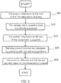
- the reference position information of the first electromagnet provided on the upstream side of the high-energy-beam irradiation-system line and the second electromagnet provided on the downstream side thereof is prestored in the storage unit, and then the positions and attitudes of the first electromagnet and the second electromagnet are adjusted at the time of their realignment, on the basis of the reference position information stored in the storage unit.
- the positions and attitudes of the electromagnets even if the building deforms due to seasonal variation in outside air, crustal movement or the like.
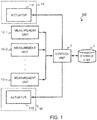
- the storage unit 3 is configured with a storage medium such as a hard disk, a removable disk, a memory or the like, in which, at the time of installation of the particle beam irradiation system (at the time of first alignment), position information about positions, attitudes and the like, of the electromagnets 1 measured by the cameras 10 is stored as the reference positions.
- a storage medium such as a hard disk, a removable disk, a memory or the like
- Step S53 When the position information at the time of the realignment of the electromagnets 1 (1A, 1B) is acquired in Step S53, the control unit 2 then takes out the position information of the reference positions from the storage unit 3, to thereby calculate the displacement amounts by comparing the position information at the time of the realignment of the electromagnets 1 (1A, 1B) with the position information of the reference positions (Step S54).
- the control unit 2 outputs control information such as an actuation amount or the like, to any one of the actuators of the electromagnets 1 (1A, 1B) for the vertical direction (11A-1, 11A-2, 11A-3, 11B-1, 11B-2, 11B-3) and the actuators thereof for the horizontal directions (11A-4, 11A-5, 11B-4, 11B-5), to thereby instruct it to cause actuation, so that the positions, attitudes and the like, of the electromagnets 1 (1A, 1B) are adjusted.
- control information such as an actuation amount or the like
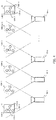
- the relative position information is acquired using the plurality of cameras 10 (10-1, 10-2, ⁇ , 10-n), even if the main electromagnet placed on the upstream side of the HEBT system line and the electromagnet placed on the downstream side thereof are distantly positioned, for example, they are placed on different floors in the building, it is possible to precisely adjust the electromagnets while keeping their relative positions, attitudes and the like. This makes it possible to achieve highly-precise beam irradiation.
- FIG. 6 is a block diagram showing a configuration of particle beam irradiation equipment 200 according to Embodiment 2 of the invention.
- FIG. 7 is an external view of an electromagnet for particle beam irradiation system, which is provided with the particle beam irradiation equipment 200.
- the control unit 2 causes the storage unit 3 to prestore the position information about the measured positions, attitudes and the like, of the electromagnets 1 (1A, 1B), and at the time of the realignment, the control unit calculates, using the deformation simulator 4, deformation amounts of the building, the apparatuses and the like, to thereby acquire position information of the electromagnets 1 (1A, 1B) at the time of the realignment, based on the position information as the reference positions stored in the storage unit 3.
- Configuration and operations other than the above, of the particle beam irradiation equipment 200 are similar to those in the configuration and the operations of the particle beam irradiation equipment 100 of Embodiment 1 shown in FIG. 1 and FIG. 5 , so that the same reference numerals are given to the same parts and description thereof is omitted here.
- the control unit 2 causes the storage unit 3, at the time of the first alignment, to prestore the position information about the measured positions, attitudes and the like, of the electromagnets 1 (1A, 1B), and then acquires the displacement amounts, based on the position information as the reference positions stored in the storage unit 3, and from the position information of the electromagnets 1 (1A, 1B) acquired by the deformation simulator 4 at the time of the realignment.
- the storage unit 3 at the time of the first alignment, to prestore the position information about the measured positions, attitudes and the like, of the electromagnets 1 (1A, 1B), and then acquires the displacement amounts, based on the position information as the reference positions stored in the storage unit 3, and from the position information of the electromagnets 1 (1A, 1B) acquired by the deformation simulator 4 at the time of the realignment.
- the apparatuses and the like are calculated using the deformation simulator 4, even if the main electromagnet placed on the upstream side of the HEBT system line and the electromagnet placed on the downstream side thereof are distantly positioned, for example, they are placed on different floors in the building, it is possible to precisely adjust the electromagnets while keeping their relative positions, attitudes and the like. This makes it possible to achieve highly-precise beam irradiation.
- the position information at the time of the realignment of the electromagnets 1 (1A, 1B) is acquired by the deformation simulator 4, at the time of the realignment; however, this is not limitative.
- the displacement amounts of the electromagnets 1 (1A, 1B) may be estimated at the time of the first alignment, based on the position information that is the reference positions stored in the storage unit 3. This also allows to recognize the time when the realignment becomes necessary, thus making it possible to create a plan for realignment beforehand.
- FIG. 8 is a block diagram showing a configuration of particle beam irradiation equipment 300 according to Embodiment 3 of the invention.
- FIG. 9 is an external view of an electromagnet 1 A for particle beam irradiation system, which is provided with the particle beam irradiation equipment 300.
- the transmitted position information from the GPS transmitters 13 (13A, 13B) is received by the GPS receiver 5 placed at an original point in the building (for example, at a center point of the synchrotron).
- the position of the GPS receiver 5 viewed from the electromagnets 1 (1A, 1B) having the respective sets of three GPS transmitters 13 (13A, 13B) is determined.
- back calculation is applied using the position of the GPS receiver 5 as the original point, it is possible to calculate the relative positions, attitudes and the like, of the electromagnet 1A and the electromagnet 1B at the time the GPS receiver 5 is regarded as a reference.
- the control unit 2 causes the storage unit 3, at the time of the first alignment, to store as position information of the reference positions, the position information of the electromagnets 1 (1A, 1B) acquired from the position information transmitted from the GPS transmitters 13 (13A, 13B), using the position of the GPS receiver 5 as the original point, and then acquires the displacement amounts, based on the position information of the reference positions stored in the storage unit 3, and from the position information of the electromagnets 1 (1A, 1B) acquired from the position information transmitted from the GPS transmitters 13 (13A, 13B), at the time of the realignment, using the position of the GPS receiver 5 as the original point.
- the control unit 2 causes the storage unit 3, at the time of the first alignment, to store as position information of the reference positions, the position information of the electromagnets 1 (1A, 1B) acquired from the position information transmitted from the GPS transmitters 13 (13A, 13B), using the position of the GPS receiver 5 as the original point, and then acquires the displacement amounts, based on the position information of the reference positions stored
- Embodiments 1 to 3 there is described that the positions, attitudes and the like, of the electromagnet 1A and the electromagnet 1B are both adjusted; however, this is not limitative. When either one of the electromagnet 1A and the electromagnet 1B is adjusted so that their relative positions and attitudes are kept, this also makes it possible to achieve highly-precise beam irradiation.
- the alignment of the electromagnets when they are placed on different floors in the building, it is general that the electromagnet nearer to the ground is not moved but the electromagnet on the upper floor, which is easily influenced by expansion/contraction of the building, is solely adjusted so that their relative positions are unchanged.
Landscapes
- Engineering & Computer Science (AREA)
- Physics & Mathematics (AREA)
- Health & Medical Sciences (AREA)
- Biomedical Technology (AREA)
- Spectroscopy & Molecular Physics (AREA)
- Plasma & Fusion (AREA)
- Electromagnetism (AREA)
- Public Health (AREA)
- General Health & Medical Sciences (AREA)
- Pathology (AREA)
- Nuclear Medicine, Radiotherapy & Molecular Imaging (AREA)
- Radiology & Medical Imaging (AREA)
- Life Sciences & Earth Sciences (AREA)
- Animal Behavior & Ethology (AREA)
- Veterinary Medicine (AREA)
- General Engineering & Computer Science (AREA)
- High Energy & Nuclear Physics (AREA)
- Optics & Photonics (AREA)
- Power Engineering (AREA)
- Particle Accelerators (AREA)
- Radiation-Therapy Devices (AREA)
Applications Claiming Priority (1)
| Application Number | Priority Date | Filing Date | Title |
|---|---|---|---|
| PCT/JP2014/081515 WO2016084218A1 (ja) | 2014-11-28 | 2014-11-28 | 粒子線照射設備 |
Publications (2)
| Publication Number | Publication Date |
|---|---|
| EP3226251A1 true EP3226251A1 (de) | 2017-10-04 |
| EP3226251A4 EP3226251A4 (de) | 2018-05-23 |
Family
ID=56073833
Family Applications (1)
| Application Number | Title | Priority Date | Filing Date |
|---|---|---|---|
| EP14907083.1A Withdrawn EP3226251A4 (de) | 2014-11-28 | 2014-11-28 | Partikelstrahlbestrahlungsausrüstung |
Country Status (6)
| Country | Link |
|---|---|
| US (1) | US10199148B2 (de) |
| EP (1) | EP3226251A4 (de) |
| JP (1) | JP6180658B2 (de) |
| CN (1) | CN107077904B (de) |
| TW (1) | TWI590850B (de) |
| WO (1) | WO2016084218A1 (de) |
Families Citing this family (3)
| Publication number | Priority date | Publication date | Assignee | Title |
|---|---|---|---|---|
| JP7278859B2 (ja) * | 2019-04-26 | 2023-05-22 | 東芝エネルギーシステムズ株式会社 | 荷電粒子加速装置及びその調整方法 |
| JP7313241B2 (ja) * | 2019-09-10 | 2023-07-24 | 株式会社日立製作所 | 据付調整量算出方法及び据付調整量算出システム |
| JP2024511277A (ja) | 2021-02-19 | 2024-03-13 | メビオン・メディカル・システムズ・インコーポレーテッド | 粒子線治療システムのためのガントリー |
Family Cites Families (10)
| Publication number | Priority date | Publication date | Assignee | Title |
|---|---|---|---|---|
| JPH06163197A (ja) * | 1992-11-16 | 1994-06-10 | Ishikawajima Harima Heavy Ind Co Ltd | アライメント用ターゲット付電磁石および電磁石のアライメント方法 |
| JP3190923B2 (ja) * | 1993-04-26 | 2001-07-23 | 川崎重工業株式会社 | 加速器の磁石アライメント調整方法及び装置 |
| JPH11137699A (ja) * | 1997-11-13 | 1999-05-25 | Hitachi Medical Corp | 放射線治療装置 |
| JP4487313B2 (ja) * | 2005-04-25 | 2010-06-23 | 株式会社日立プラントテクノロジー | 電磁石のアライメント方法およびアライメントシステム |
| JP2006344466A (ja) * | 2005-06-08 | 2006-12-21 | Hitachi Plant Technologies Ltd | 電磁石の位置調整装置 |
| JP4457353B2 (ja) * | 2005-11-25 | 2010-04-28 | 株式会社日立プラントテクノロジー | 調整ボルトの操作方法および電磁石の位置・姿勢調整方法 |
| JP2009217938A (ja) | 2008-03-07 | 2009-09-24 | Hitachi Ltd | 加速器システム及び粒子線治療システム |
| JP5609073B2 (ja) * | 2009-06-16 | 2014-10-22 | カシオ計算機株式会社 | 測位装置、測位方法およびプログラム |
| JP2011182987A (ja) * | 2010-03-09 | 2011-09-22 | Sumitomo Heavy Ind Ltd | 加速粒子照射設備 |
| JP5818718B2 (ja) * | 2012-02-28 | 2015-11-18 | 三菱重工業株式会社 | 放射線治療装置制御装置、放射線治療装置制御方法及び放射線治療装置のコンピュータに実行されるプログラム |
-
2014
- 2014-11-28 EP EP14907083.1A patent/EP3226251A4/de not_active Withdrawn
- 2014-11-28 WO PCT/JP2014/081515 patent/WO2016084218A1/ja not_active Ceased
- 2014-11-28 JP JP2016561182A patent/JP6180658B2/ja active Active
- 2014-11-28 CN CN201480083323.XA patent/CN107077904B/zh not_active Expired - Fee Related
- 2014-11-28 US US15/515,345 patent/US10199148B2/en not_active Expired - Fee Related
-
2015
- 2015-04-07 TW TW104111082A patent/TWI590850B/zh not_active IP Right Cessation
Also Published As
| Publication number | Publication date |
|---|---|
| US10199148B2 (en) | 2019-02-05 |
| CN107077904B (zh) | 2019-06-07 |
| US20170236631A1 (en) | 2017-08-17 |
| TW201618829A (zh) | 2016-06-01 |
| JP6180658B2 (ja) | 2017-08-16 |
| TWI590850B (zh) | 2017-07-11 |
| EP3226251A4 (de) | 2018-05-23 |
| WO2016084218A1 (ja) | 2016-06-02 |
| CN107077904A (zh) | 2017-08-18 |
| JPWO2016084218A1 (ja) | 2017-04-27 |
Similar Documents
| Publication | Publication Date | Title |
|---|---|---|
| EP3226251A1 (de) | Partikelstrahlbestrahlungsausrüstung | |
| CN112650076B (zh) | 一种星群协同控制地面仿真系统 | |
| CN106357313A (zh) | 面向无人机通信的mimo 中继信道中断概率计算方法 | |
| EP3422476A1 (de) | Elektromagnetisches feldmuster für phasengesteuerte gruppenantenne | |
| Muralidharan et al. | Stationkeeping in Earth-Moon near rectilinear halo orbits | |
| Xie et al. | UAV-carried long-distance Wi-Fi communication infrastructure | |
| Cassell et al. | Design and execution of the hypersonic inflatable aerodynamic decelerator large-article wind tunnel experiment | |
| Hoffman et al. | NASA-ISRO synthetic aperture radar (NISAR) mission: System integration & test | |
| Castillo et al. | Autonomous UAV landing on a moving vessel: Localization challenges and implementation framework | |
| US20200020163A1 (en) | Augmented Reality System with an Active Portable Anchor | |
| Williamsen et al. | Characterizing the orbital debris environment using satellite perturbation anomaly data | |
| Heinkelmann et al. | Very long baseline interferometry: accuracy limits and relativistic tests | |
| KR101227911B1 (ko) | 교란신호 발생원 위치추적용 모사신호 발생시스템 | |
| Lumsdaine et al. | Design of the wendelstein 7-x inertially cooled test divertor unit scraper element | |
| Tresvig et al. | Investigating the coupling effects between CubeSTAR's communication antenna and deployable payload sensors [Measurements Corner] | |
| Vogiatzis et al. | Aerothermal modeling for design support, requirement validation, and performance assessment of the GMT subsystems | |
| Lane et al. | Correlation and error metrics for plant identification of on-orbit space structures | |
| Keil et al. | An attitude model for the spacecraft of the ESA mission Gaia | |
| RU15046U1 (ru) | Система для прогнозирования результатов натурных испытаний беспилотного летательного аппарата | |
| CN105572634B (zh) | 双星时差频差定位缩比试验方法 | |
| Calabro | Relativistic aberrational interstellar navigation | |
| Hinterreiter et al. | Why are ELEvoHI CME arrival predictions different if based on STEREO-A or STEREO-B heliospheric imager observations? | |
| Allica et al. | Architecture of gaia satellite phased array antenna | |
| Azankpo | Surface accuracy and pointing error prediction of a 32 m diameter class radio astronomy telescope | |
| Buonagura et al. | The Role of Autonomy in Close Proximity Operations Around Asteroid (99942) Apophis |
Legal Events
| Date | Code | Title | Description |
|---|---|---|---|
| STAA | Information on the status of an ep patent application or granted ep patent |
Free format text: STATUS: THE INTERNATIONAL PUBLICATION HAS BEEN MADE |
|
| PUAI | Public reference made under article 153(3) epc to a published international application that has entered the european phase |
Free format text: ORIGINAL CODE: 0009012 |
|
| STAA | Information on the status of an ep patent application or granted ep patent |
Free format text: STATUS: REQUEST FOR EXAMINATION WAS MADE |
|
| 17P | Request for examination filed |
Effective date: 20170522 |
|
| AK | Designated contracting states |
Kind code of ref document: A1 Designated state(s): AL AT BE BG CH CY CZ DE DK EE ES FI FR GB GR HR HU IE IS IT LI LT LU LV MC MK MT NL NO PL PT RO RS SE SI SK SM TR |
|
| AX | Request for extension of the european patent |
Extension state: BA ME |
|
| DAX | Request for extension of the european patent (deleted) | ||
| A4 | Supplementary search report drawn up and despatched |
Effective date: 20180423 |
|
| RIC1 | Information provided on ipc code assigned before grant |
Ipc: G21K 5/04 20060101AFI20180417BHEP Ipc: A61N 5/10 20060101ALI20180417BHEP Ipc: H05H 7/10 20060101ALI20180417BHEP Ipc: H01F 7/20 20060101ALI20180417BHEP Ipc: H05H 7/04 20060101ALI20180417BHEP |
|
| STAA | Information on the status of an ep patent application or granted ep patent |
Free format text: STATUS: EXAMINATION IS IN PROGRESS |
|
| 17Q | First examination report despatched |
Effective date: 20210708 |
|
| STAA | Information on the status of an ep patent application or granted ep patent |
Free format text: STATUS: THE APPLICATION HAS BEEN WITHDRAWN |
|
| 18W | Application withdrawn |
Effective date: 20211022 |