EP3227067B1 - Impulseur et procédé pour son utilisation - Google Patents
Impulseur et procédé pour son utilisation Download PDFInfo
- Publication number
- EP3227067B1 EP3227067B1 EP15865954.0A EP15865954A EP3227067B1 EP 3227067 B1 EP3227067 B1 EP 3227067B1 EP 15865954 A EP15865954 A EP 15865954A EP 3227067 B1 EP3227067 B1 EP 3227067B1
- Authority
- EP
- European Patent Office
- Prior art keywords
- impeller
- intermediate plate
- products
- paddles
- opening
- Prior art date
- Legal status (The legal status is an assumption and is not a legal conclusion. Google has not performed a legal analysis and makes no representation as to the accuracy of the status listed.)
- Active
Links
Images



Classifications
-
- B—PERFORMING OPERATIONS; TRANSPORTING
- B26—HAND CUTTING TOOLS; CUTTING; SEVERING
- B26D—CUTTING; DETAILS COMMON TO MACHINES FOR PERFORATING, PUNCHING, CUTTING-OUT, STAMPING-OUT OR SEVERING
- B26D7/00—Details of apparatus for cutting, cutting-out, stamping-out, punching, perforating, or severing by means other than cutting
- B26D7/06—Arrangements for feeding or delivering work of other than sheet, web, or filamentary form
- B26D7/0691—Arrangements for feeding or delivering work of other than sheet, web, or filamentary form by centrifugal force
-
- B—PERFORMING OPERATIONS; TRANSPORTING
- B26—HAND CUTTING TOOLS; CUTTING; SEVERING
- B26D—CUTTING; DETAILS COMMON TO MACHINES FOR PERFORATING, PUNCHING, CUTTING-OUT, STAMPING-OUT OR SEVERING
- B26D7/00—Details of apparatus for cutting, cutting-out, stamping-out, punching, perforating, or severing by means other than cutting
- B26D7/08—Means for treating work or cutting member to facilitate cutting
-
- B—PERFORMING OPERATIONS; TRANSPORTING
- B26—HAND CUTTING TOOLS; CUTTING; SEVERING
- B26D—CUTTING; DETAILS COMMON TO MACHINES FOR PERFORATING, PUNCHING, CUTTING-OUT, STAMPING-OUT OR SEVERING
- B26D1/00—Cutting through work characterised by the nature or movement of the cutting member or particular materials not otherwise provided for; Apparatus or machines therefor; Cutting members therefor
- B26D1/01—Cutting through work characterised by the nature or movement of the cutting member or particular materials not otherwise provided for; Apparatus or machines therefor; Cutting members therefor involving a cutting member which does not travel with the work
- B26D1/02—Cutting through work characterised by the nature or movement of the cutting member or particular materials not otherwise provided for; Apparatus or machines therefor; Cutting members therefor involving a cutting member which does not travel with the work having a stationary cutting member
- B26D1/03—Cutting through work characterised by the nature or movement of the cutting member or particular materials not otherwise provided for; Apparatus or machines therefor; Cutting members therefor involving a cutting member which does not travel with the work having a stationary cutting member with a plurality of cutting members
-
- B—PERFORMING OPERATIONS; TRANSPORTING
- B26—HAND CUTTING TOOLS; CUTTING; SEVERING
- B26D—CUTTING; DETAILS COMMON TO MACHINES FOR PERFORATING, PUNCHING, CUTTING-OUT, STAMPING-OUT OR SEVERING
- B26D3/00—Cutting work characterised by the nature of the cut made; Apparatus therefor
- B26D3/28—Splitting layers from work; Mutually separating layers by cutting
Definitions
- the present invention generally relates to methods and machines for cutting products.
- the invention particularly relates to machines equipped with an impeller adapted to transport products to at least one knife suitable for cutting the product, wherein the impeller is capable of transporting and orienting products that are relatively small, for example, the size of a small potato and smaller.
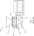
- FIG. 1 A widely used line of machines for this purpose is commercially available from Urschel Laboratories, Inc., under the name Urschel Model CC ® , an embodiment of which is represented in FIG. 1 .
- the Model CC ® machine line provides versions of centrifugal-type slicers capable of producing uniform slices, strip cuts, shreds and granulations of a wide variety of products at high production capacities.
- the Model CC ® line of machines can make use of substantially round potatoes to produce the desired circular chip shape with a minimum amount of scrap.
- US2002/0144584 and US2014/0116213 each describe methods and equipment for cutting food products. More particularly, US2002/0144584 describes an impeller for use in a rotary food slicing machine comprising a rear base plate and at least one forward ring secured in axial spaced parallel relation relative to the rear base plate and a plurality of circumferentially spaced planar paddles spanning the base plate and the forward ring, and US2014/0116213 describes an impeller for use in a food cutting apparatus, adapted to be mounted coaxially within a cutting head having one or more cutting knives disposed about a circumference thereof, equipped with paddles such that, as the impeller rotates within the cutting head, the paddles force food product radially outward toward the stationary cutting knives of the cutting head.
- the Model CC ® machine 10 schematically represented in FIG. 1 includes a cutting head 12 mounted on a support ring 15 above a gear box 16.
- a housing 18 contains a shaft coupled to the gear box 16 that rotates an impeller 14 within the cutting head 12.
- Products are delivered to the cutting head 12 and impeller 14 through a feed hopper 11 located above the cutting head 12.
- the impeller 14 is coaxially mounted within the cutting head 12, which is generally annular-shaped with cutting knives (not shown) mounted at its perimeter.
- the impeller 14 rotates within the cutting head 12, while the latter remains stationary.
- the hopper 11 delivers products to the middle of the impeller 14, and centrifugal force causes the products to move outward into engagement with the knives of the cutting head 12.
- FIG. 2 is a perspective view of a cutting head 12 and FIGS. 3 and 4 are perspective and cross-sectional views, respectively, of an impeller 14 of types that can be used in the Model CC ® machine of FIG. 1 .
- each knife 13 of the cutting head 12 projects radially inward toward the interior of the cutting head 12, generally in a direction opposite the rotation of the impeller 14 within the cutting head 12, and defines a cutting edge at its radially innermost extremity.
- the impeller 14 comprises generally radially-oriented paddles 28 disposed between a base 30 and an upper ring 32, the latter being omitted in FIG. 4 to reveal the interior of the impeller 14 and orientations of the paddles 28.
- a frustoconical-shaped flange 34 extends in a generally axial direction from the ring 32 to define an opening 36 through which food products enter the impeller 14.
- the paddles 28 have faces 38 that engage and direct the products (e.g., potatoes) 39 radially outward towards and against the knives 13 of the cutting head 12 as the impeller 14 rotates.
- the cutting head 12 shown in FIG. 2 comprises a lower support ring 18, an upper support ring 20, and circumferentially-spaced support segments (shoes) 22.
- the knives 13 of the cutting head 12 are individually secured with clamping assemblies 26 to the shoes 22.
- Each clamping assembly 26 includes a knife holder 26A mounted to the radially inward-facing side of a shoe 22, and a clamp 26B mounted on the radially outward-facing side of a shoe 22 to secure the knife 13 to the knife holder 26A.
- the shoes 22 are represented as being secured with bolts 25 to the support rings 18 and 20.
- the shoes 22 are equipped with coaxial pivot pins (not shown) that engage holes in the support rings 18 and 20. By pivoting on its pins, the orientation of a shoe 22 can be adjusted to alter the radial location of the cutting edge of its knife 13 with respect to the axis of the cutting head 12, thereby controlling the thickness of the sliced product. As an example, adjustment can be achieved with an adjusting screw and/or pin 24 located circumferentially behind the pivot pins.
- FIG. 2 further shows optional gate insert strips 23 mounted to each shoe 22, which the product crosses prior to encountering the knife 13 mounted to the succeeding shoe 22.
- the knives 13 shown in FIG. 2 are depicted as having straight cutting edges for producing flat slices, though other shapes are also used to produce sliced, strip-cut, shredded and granulated products.
- the knives 13 can have cutting edges that define a periodic pattern of peaks and valleys when viewed edgewise.
- the periodic pattern can be characterized by sharp peaks and valleys, or a more corrugated or sinusoidal shape characterized by more rounded peaks and valleys when viewed edgewise.
- each knife 13 If the peaks and valleys of each knife 13 are aligned with those of the preceding knife 13, slices are produced in which each peak on one surface of a slice corresponds to a valley on the opposite surface of the slice, such that the slices are substantially uniform in thickness but have a cross-sectional shape that is characterized by sharp peaks and valleys ("V-slices”) or a more corrugated or sinusoidal shape (crinkle slices), collectively referred to herein as periodic shapes.
- V-slices sharp peaks and valleys
- crinkle slices a more corrugated or sinusoidal shape
- shredded product can be produced if each peak of each knife 13 is aligned with a valley of the preceding knife 13, and waffle/lattice-cut product can be produced by intentionally making off-axis alignment cuts with a periodic-shaped knife, for example, by crosscutting a product at two different angles, typically ninety degrees apart.
- strip-cut and granulated products can be produced with the use of additional knives and/or cutting wheels located downstream of the knives 13. Whether a sliced, strip-cut, shredded, granulated, or waffle-cut product is desired will depend on the intended use of the product.
- Equipment currently available for cutting product are well suited for producing slices of a wide variety of food products. Even so, further improvements and versatility are desirable, particularly for producing slices, strip cuts, shreds and granulations from a wider variety of products at high production capacities. For example, under certain conditions it is desirable to process food products that are smaller than potatoes of sizes commonly used to produce potato chips, for example, food products having diameters of less than two to three inches. Particular but nonlimiting examples include food products such as almonds, coffee beans, strawberries, mushrooms, etc. For smaller products such as these, the products tend to encounter only a limited portion of each knife 13 at the lower end of the cutting head 12 (as viewed in FIG. 2 ).
- the impeller 14 may also be desirable for the impeller 14 to deliver smaller elongate products (for example, almonds, coffee beans) so that their major dimension has a particular orientation to the cutting head 12, for example, so that the major axis of each product is oriented to be functionally tangent to the outer diameter of the impeller 14, so that a majority of the cuts through the products are lengthwise and nearly parallel to their major axes.
- smaller elongate products for example, almonds, coffee beans
- an impeller is adapted to be coaxially mounted within an annular-shaped cutting head for rotation about an axis of the cutting head in a rotational direction relative to the cutting head.
- the impeller includes a base and a ring spaced axially from each other, and a flange that extends in a generally axial direction from the ring to define an entrance to the impeller through which products enter the impeller.
- the impeller is characterized in that one or more intermediate plates are disposed between the base and the ring so as to define at least first and second tier levels within the impeller, and paddles are disposed between the base and the ring.
- the first tier level is an upper tier level within the impeller and the second tier level is a lower tier level within the impeller. At least a portion of each paddle is disposed within at least one of the first and second tier levels.
- the first tier level is between the ring and the first intermediate plate, and the second tier level is between the first intermediate plate and the base.
- the first intermediate plate has an annular shape that includes a substantially planar portion surrounding a frustoconical flange that extends in a generally axial direction from the planar portion, the flange defining an opening that is concentric with the rotational axis of the impeller, is smaller than the entrance in the ring, and defines a passage between the first and second tier levels through which products are able to pass to enter the second tier level such that the first intermediate plate functions as a baffle whereby a fraction of the products entering the impeller through the entrance is captured within the first tier level as a result of encountering and being deflected by the planar portion or the flange of the first intermediate plate and a second fraction of the products entering the impeller passes through the opening in the first intermediate plate and is captured within the second tier level beneath the opening of the first intermediate plate.
- the paddles are disposed between the base and the ring, at least a portion of each paddle being disposed within at least one of the first and second tier levels.
- Each paddle has a radially outer extremity adjacent an outer perimeter of the impeller, an oppositely-disposed radially inner extremity, and a face between the radially inner and outer extremities and facing the rotational direction of the impeller.
- the impeller further has pockets defined within each of the first and second tier levels. Each pocket is disposed between a pair of the paddles that are immediately adjacent each other in the rotational direction of the impeller, and each pocket is further delimited in an axial direction of the impeller by the base, the ring, and at least the first intermediate plate.
- a machine adapted to cut products includes an impeller of a type described above, and further includes a cutting head having at least one knife extending radially inward toward the impeller in a direction opposite the rotational direction of the impeller.
- Such a method includes rotating the impeller, supplying products to the impeller through an entrance defined by the ring, stratifying the products among the first and second tiers with the first intermediate plate and the opening therein, and propelling the products into the pockets through action of rotating the impeller.
- impellers, machines, and methods described above preferably include the ability of an impeller to vertically stratify the products as they are delivered to a cutting head located at and surrounding the outer perimeter of the impeller, so that a greater portion of the length of each knife is used to cut the products, particularly if the products are relatively small, for example, food products having diameters of less than two or three inches.
- Other technical effects of the impellers, machines, and methods include the ability of the impeller to deliver smaller elongate products (for example, almonds, coffee beans) so that their major dimension has a particular orientation to the cutting head, for example, so that a majority of the cuts through the products are lengthwise and nearly parallel to their major axes.
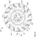
- FIGS. 5 and 6 show an impeller 40 in accordance with a nonlimiting embodiment of the present invention.
- the impeller 40 is configured for rotation, for example, within a cutting head similar to the cutting head 12 of FIG. 2 , as well as other configurations of cutting heads having an annular shape within which the impeller 40 can be installed for rotation, as discussed above in reference to FIGS. 1 through 4 .
- the impeller 40 will be described below in reference to the cutting head 12 of FIG. 2 , though it should be understood that the impeller 40 can find suitable use in cutting heads other than what is shown in FIG. 2 .
- the impeller 40 is shown in FIGS. 5 and 6 as comprising generally radially-oriented paddles 42 disposed between a base 44 and an upper ring 46 (not shown in FIG. 6 to reveal the interior of the impeller 40).
- the base 44 and ring 46 are represented in the embodiment of FIG. 5 as being parallel to each other and perpendicular to the axis of rotation of the impeller 40.
- a frustoconical-shaped flange 48 extends in a generally axial direction from the ring 46 to define an entrance or opening 50 through which products 54 ( FIG. 6 ) enter the impeller 40.
- Each paddle 42 has a radially outermost extremity adjacent and preferably contiguous with the outer perimeter of the impeller 40, an oppositely-disposed radially innermost extremity, and a face 52 between the radially inner and outer extremities and facing the rotational direction of the impeller 40.
- the faces 52 of the paddles 42 define surfaces that engage and direct the products 54 radially outward toward and against the cutting head 12 surrounding the impeller 40 as the impeller 40 rotates, and in particular to encounter the knives 13 of the cutting head 12 where the products 54 undergo a slicing operation.
- FIGS. 5 and 6 show the face 52 of each paddle 42 as being a planar surface, though other surface configurations are possible. Suitable dimensions for the paddles 42 will depend in part on the size of the products being processed, and therefore can vary considerably. For accommodating products with diameters less than two or three inches (about five or eight centimeters), a suitable width for each paddle 42 is about 1.5 inches as measured between the radially outermost and innermost extents of each paddle face 52 in a direction perpendicular to the axis of the impeller 40. The number of paddles 42 within the impeller 40 can be varied, i.e., greater or less than the fifteen paddles 42 shown for the embodiment in FIGS. 5 and 6 .
- the paddles 42 differ in construction and configuration from the prior art paddles 28 of FIGS. 3 and 4 .
- the impeller 40 is preferably an assembly constructed of individually formed paddles 42 mounted and secured between the base 44 and ring 46.
- each paddle 42 is individually mounted to the base 44 and ring 46 with bolts 56 and pins 58 that are received in corresponding holes formed in the base 44 and ring 46.
- the impeller 40 and its components can be formed by casting as well as other processes, and formed of various materials in addition to commonly-used MAB (manganese aluminum bronze) alloys.
- each paddle face 52 is shown in FIG. 6 as being positive, meaning that the radially innermost extent of each paddle face 52 is angled toward the direction of rotation of the impeller 40 relative to a radial 80 of the impeller 40, as indicated for one of the paddles 42 in FIG. 6 .
- the pitch of the paddle faces 52 could be negative (such as the orientation seen in FIG. 4 ) or neutral (meaning that the face 52 of each paddle 42 entirely lies on a radial (80) of the impeller 40).
- a single set of holes is represented as being provided for the bolts 56 and pins 58 of each paddle 42 so that the paddles 42 for a given impeller 40 are limited to having a negative, neutral, or positive pitch, as may be desired.
- multiple sets of mounting holes could be provided in the base 44 and ring 46 to enable reorientation of the pitch of each paddle 42 on the impeller 40.
- FIGS. 5 and 6 depict the impeller 40 as comprising intermediate plates 60A and 60B that are disposed between the base 44 and ring 46.
- the intermediate plates 60A and 60B define tier levels within the impeller 40, each capable of receiving products.
- the plates 60A and 60B are represented as being oriented to be substantially parallel to each other and to the base 44 and ring 46, and therefore also perpendicular to the axis of the impeller 40. Though two plates 60A and 60B are represented within the impeller 40, a single plate or more than two plates could be utilized.
- Each paddle 42 is preferably continuous between the base 44 and ring 46, and therefore passes through the intermediate plates 60A and 60B, as evident from FIG.
- each paddle 42 depicted in FIG. 5 could be made up of multiple paddles, each entirely disposed within a single tier level of the impeller 40.
- the paddles 42 defined pockets 68 within each tier level, with each pocket 68 being disposed between a pair of paddles 42 that are immediately adjacent each other in the direction of rotation of the impeller 40.
- Each pocket 68 is also delimited in the axial direction of the impeller 40 by two of the base 44, ring 46, and intermediate plates 60A and 60B.
- the paddles 42 are equi-angularly spaced at the outer perimeter of the impeller 40, such that the pockets 68 are substantially identical.
- two intermediate plates 60A and 60B define three tier levels 70A, 70B and 70C between the base 44 and ring 46.
- Each intermediate plate 60A and 60B has a generally annular shape that includes a substantially planar portion 62A and 62B, respectively, surrounding a frustoconical flange 64A and 64B, respectively, that extends in a generally axial direction from the planar portion 62A/62B.
- each plate 60A/60B defines an opening 66A or 66B that is concentric with the axis of the impeller 40 and defines passages between the tiers 70A, 70B and 70C through which products are able to pass to enter one of the lower tier levels 70B and 70C beneath the opening 66A or 66B, such that the plates 60A and 60B include the ability to function as baffles. For example, a fraction of the products that enter the impeller 40 through its opening 50 ( FIG.
- the intermediate plates 60A and 60B serve to axially (vertically) stratify the distribution of products within the impeller 40, with the result that a greater portion of the length of each cutting head knife 13 will be used to slice the products than would otherwise likely occur.
- the size and number of paddles 42 and plates 60A and 60B can be varied to influence the stratification and distribution of products within the impeller 40.
- the axial distances between the base 44, ring 46, and plates 60A and 60B can be tailored to influence the stratification and distribution of products within the impeller 40.
- FIG. 7 depicts an impeller 40 that is similar to the impeller 40 of FIGS. 5 and 6 except for the number of intermediate plates 60 and tier levels 70 defined within the impeller 40.
- the relative sizes of the openings 66 within the plates 60A and 60B (60 in FIG. 7 ) will influence the relative fractions of products that enter the tier levels 70A, 70B and 70C (70 in FIG. 7 ), and as such their relative sizes can be tailored to promote a desired stratification of products among the tier levels 70A, 70B, and 70C (70 in FIG. 7 ).
- the size of the impeller 40 can also be tailored for processing different sized products, such that the size of the pockets 68 can be tailored to receive and orient a particular product of a particular size during the process of being sequentially cut by the circumferential series of knives 13 mounted to the cutting head 12 in which the impeller 40 is installed and rotating.
- the surface conditions of the base 44 and plates 60A and 60B 60 in FIG.
- the surfaces of the base 44 and plates 60A and 60B (60 in FIG. 7 ) facing the opening 50 of the impeller 40 may be blast finished, polished, and/or grooved for this purpose to promote a desired effect. It is further believed that the manner and speed with which products can be transferred to the pockets 68 and stabilized within the pockets 68 can be promoted by ensuring that at least the planar portions 62A and 62B (62 in FIG. 7 ) of the plates 60A and 60B (60 in FIG. 7 ) are parallel to the base 44 and/or perpendicular to the axis of the impeller 40.
- FIGS. 5 and 6 further show the impeller 40 equipped with attachments 72 extending from the radially innermost extent of each paddle 42.
- each attachment 72 forms a restricted opening 74 to a pocket 68 at the radially innermost extents of an adjacent pair of paddles 42 that form the pocket 68.
- the openings 74 are restricted in the sense that each has a circumferential extent (i.e., its width in the direction of rotation of the impeller 40) that is narrower than the circumferential extent of its corresponding pocket 68 (i.e., the distance between the pair of paddles 42 that form the pocket 68).
- the intended purpose of the restricted opening 74 is to promote the ability of the impeller 40 to deliver relatively small elongate products (for example, almonds, coffee beans, etc.) so that their major dimension has a particular orientation to the cutting head 12, preferably so that the major axis of each product is oriented to be functionally tangent to the outer diameter of the impeller 40, so that a majority of the cuts through the products are lengthwise and nearly parallel to their major axes.
- the attachments 72 shown in FIG. 6 reduce the entrances to the pockets 68 by roughly twenty-five percent, though lesser and greater restrictions are foreseeable.
- each attachment 72 may be continuous between the base 44 and ring 46. In other words, a single attachment 72 is attached to each paddle 42 and passes through the intermediate plates 60A and 60B. Alternatively, multiple attachments 72 may be attached to each paddle 42, which each attachment 72 disposed between an adjacent pair of the base 44, ring 46, and plates 60A and 60B.
- Each attachment 72 is shown as being attached to or at the face 52 of its corresponding paddle 42, for example, with bolts 76, though other locations and means for attachment are foreseeable.
- a portion of each attachment 72 is represented as having a U-shaped profile when viewed along the axial direction of the impeller 40, though other shapes are foreseeable. The U-shaped portions of the attachments 72 shown in FIG.
- Each restricted opening 74 is defined by and between one of the blunt surfaces 78 and a preceding paddle 42 in the rotational direction.
- Each blunt surface 78 is represented as being roughly parallel to the preceding paddle 42, such that the resulting restricted opening 74 has a generally uniform width with the preceding paddle 42 to assist in orienting elongated products.
- the blunt surfaces 78 may also reduce the risk of damage to the products, and may be used as an attachment point for a flexible component to further reduce impact damage.
- the shapes of the attachments 72 can be readily tailored for compatibility with the particular product being processed.
- the impeller 40 and cutting head 12 could differ in appearance and construction from the embodiments shown in the figures, the functions of each component of the impeller 40 and cutting head 12 could be performed by components of different construction but capable of a similar (though not necessarily equivalent) function, and various materials and processes could be used to fabricate the impeller 40 and cutting head 12 and their components.
- the nonlimiting embodiment of the cutting head 12 shown in FIG. 2 is particularly adapted to cut products into slices, though it is foreseeable that the impeller 40 could be used in combination with a cutting head adapted for cutting other materials. Therefore, the scope of the invention is to be limited only by the following claims.
Landscapes
- Life Sciences & Earth Sciences (AREA)
- Forests & Forestry (AREA)
- Engineering & Computer Science (AREA)
- Mechanical Engineering (AREA)
- Crushing And Pulverization Processes (AREA)
Claims (16)
- Un impulseur (40) conçu pour être monté coaxialement au sein d'une tête de coupe (12) de forme annulaire en vue d'une rotation autour d'un axe de rotation de celle-ci dans une direction de rotation par rapport à la tête de coupe (12),
l'impulseur (40) comprenant :une base (44) et une bague (46) espacées axialement l'une de l'autre, et un flasque (48) qui s'étend dans une direction généralement axiale à partir de la bague (46) afin de définir une entrée (50) de l'impulseur (40) par laquelle des produits (54) entrent dans l'impulseur (40) ;caractérisé par une ou plusieurs plaques intermédiaires (60A, 60B) disposées entre la base (44) et la bague (46) et comprenant au moins une première plaque intermédiaire (60A) de sorte à définir au moins des premier et deuxième paliers (70A, 70B) au sein de l'impulseur (40), le premier palier (70A) étant un palier supérieur (70A) au sein de l'impulseur (40) et le deuxième palier (70B) étant un palier inférieur (70B) au sein de l'impulseur (40), le premier palier (70A) étant situé entre la bague (46) et la première plaque intermédiaire (60A), le deuxième palier (70B) étant situé entre la première plaque intermédiaire (60A) et la base (44), la première plaque intermédiaire (60A) ayant une forme annulaire qui inclut une portion substantiellement plane (62A) entourant un flasque (64A) tronconique qui s'étend dans une direction généralement axiale à partir de la portion plane (62A), le flasque (64A) définissant une ouverture (66A) qui est concentrique avec l'axe de rotation de l'impulseur (40) et définit un passage entre les premier et deuxième paliers (70A, 70B) par lequel des produits sont aptes à passer afin d'entrer dans le deuxième palier (70B) de telle sorte que la première plaque intermédiaire (60A) fonctionne en tant que chicane grâce à laquelle une fraction des produits entrant dans l'impulseur (40) par l'entrée (50) est capturée au sein du premier palier (70A) du fait d'avoir rencontré et d'avoir été déviée par la portion plane (62A) ou le flasque (64A) de la première plaque intermédiaire (60A) et une deuxième fraction des produits entrant dans l'impulseur (40) passe par l'ouverture (66A) dans la première plaque intermédiaire (60A) et est capturée au sein du deuxième palier (70B) sous l'ouverture (66A) de la première plaque intermédiaire (60A) ;des palettes (42) disposées entre la base (44) et la bague (46), au moins une portion de chaque palette (42) étant disposée au sein d'au moins l'un des premier et deuxième paliers (70A, 70B), chacune des palettes (42) ayant une extrémité radialement externe adjacente à un périmètre externe de l'impulseur (40), une extrémité radialement interne disposée à l'opposé, et une face (52) située entre les extrémités radialement interne et externe et faisant face à la direction de rotation de l'impulseur (40) ; etdes poches (68) définies au sein de chacun des premier et deuxième paliers (70A, 70B), chaque poche (68) étant disposée entre une paire des palettes (42) qui sont immédiatement adjacentes l'une à l'autre dans la direction de rotation de l'impulseur (40), les poches (68) étant délimitées dans une direction axiale de l'impulseur (40) par la base (44), la bague (46), et au moins la première plaque intermédiaire (60A). - L'impulseur (40) de la revendication 1, dans lequel chaque palette (42) s'étend entre la base (44) et la bague (46) et passe à travers la première plaque intermédiaire (60A) de sorte que des portions de la palette (42) sont disposées au sein des premier et deuxième paliers (70A, 70B).
- L'impulseur (40) de la revendication 1, les une ou plusieurs plaques intermédiaires (60A, 60B) comprenant en outre au moins une deuxième plaque intermédiaire (60B) disposée entre la première plaque intermédiaire (60A) et la base (44) de sorte à définir au moins un troisième palier (70C) au sein de l'impulseur (40) entre la deuxième plaque intermédiaire (60B) et la base (44), la deuxième plaque intermédiaire (60B) ayant une forme annulaire qui définit une ouverture (66B) en son sein qui est concentrique avec l'axe de rotation de l'impulseur (40), est plus petite que l'ouverture (66A) dans la première plaque intermédiaire (60A), et définit un deuxième passage entre les deuxième et troisième paliers (70B, 70C) par lequel des produits sont aptes à passer afin d'entrer dans le troisième palier (70C) sous l'ouverture (66B) à partir du deuxième palier (70B), la deuxième plaque intermédiaire (60B) fonctionnant en tant que deuxième chicane grâce à laquelle la deuxième fraction des produits est capturée au sein du deuxième palier (70B) défini entre les première et deuxième plaques intermédiaires (60A, 60B) du fait d'avoir rencontré et d'avoir été déviée par la deuxième plaque intermédiaire (60B) et une troisième fraction des produits entrant dans l'impulseur (40) par l'entrée (50) passe par l'ouverture (66B) dans la deuxième plaque intermédiaire (60B) et est capturée au sein du troisième palier (70C) sous l'ouverture (66B) de la deuxième plaque intermédiaire (60B).
- L'impulseur (40) de la revendication 3, dans lequel les palettes (42) passent à travers les première et deuxième plaques intermédiaires (60A, 60B) de sorte qu'une portion de chaque palette (42) est disposée au sein de chacun des premier, deuxième, et troisième paliers (70A, 70B, 70C).
- L'impulseur (40) de la revendication 3, dans lequel la deuxième plaque intermédiaire (60B) a une portion plane (62B) qui entoure l'ouverture (66B) en son sein.
- L'impulseur (40) de la revendication 5, dans lequel la portion plane (62B) de la deuxième plaque intermédiaire (60B) entoure un flasque (64B) tronconique qui s'étend dans la direction axiale à partir de la portion plane (62B) et entoure le deuxième passage à travers la deuxième plaque intermédiaire (60B).
- L'impulseur (40) de la revendication 3, dans lequel l'ouverture (66B) dans la deuxième plaque intermédiaire (60B) est plus petite que l'ouverture (66A) dans la première plaque intermédiaire (60A).
- L'impulseur (40) de la revendication 1, dans lequel les palettes (42) sont espacées de manière équiangulaire au niveau du périmètre externe de l'impulseur (40) et les poches (68) sont identiques.
- L'impulseur (40) de la revendication 1, comprenant en outre des fixations (72) s'étendant à partir des extrémités radialement internes des palettes (42), chacune des fixations (72) formant une ouverture restreinte (74) sur l'une des poches (68) qui est plus étroite qu'une distance entre une paire des palettes (42) qui sont immédiatement adjacentes l'une à l'autre dans la direction de rotation de l'impulseur (40).
- L'impulseur (40) de la revendication 9, dans lequel chacune des fixations (72) a une surface émoussée (78) et chacune des ouvertures restreintes (74) est définie par et entre l'une des surfaces émoussées (78) et une palette précédente des palettes (42) dans la direction de rotation.
- L'impulseur (40) de la revendication 10, dans lequel chacune des surfaces émoussées (78) est parallèle à une palette précédente des palettes (42) dans la direction de rotation et l'ouverture restreinte (74) ainsi définie a une largeur généralement uniforme dans la direction de rotation.
- L'impulseur (40) de la revendication 9, dans lequel les fixations (72) définissent les faces (52) des palettes (42).
- Une machine comprenant l'impulseur (40) de la revendication 1, la machine comprenant une tête de coupe (12) de forme annulaire ayant au moins un couteau (13) s'étendant radialement vers l'intérieur vers l'impulseur (40) dans une direction opposée à la direction de rotation de l'impulseur (40).
- Un procédé d'utilisation de l'impulseur (40) de la revendication 1, le procédé comprenant : le fait de faire tourner l'impulseur (40) ;le fait de fournir des produits à l'impulseur (40) par l'entrée (50) définie par la bague (46) ;le fait de stratifier verticalement les produits parmi les premier et deuxième paliers (70A, 70B) avec la première plaque intermédiaire (60A) et l'ouverture (66A) en son sein ; etle fait de pousser les produits à l'intérieur des poches (68) par le biais de l'action de rotation de l'impulseur (40).
- Le procédé de la revendication 14, comprenant en outre le fait d'orienter les produits afin d'avoir un axe majeur fonctionnellement tangent au périmètre externe de l'impulseur (40).
- Le procédé de la revendication 14, dans lequel l'étape d'orientation est réalisée avec des fixations (72) qui s'étendent à partir des extrémités radialement internes des palettes (42), chacune des fixations (72) formant une ouverture restreinte (74) sur l'une des poches (68) qui est plus étroite qu'une distance entre une paire des palettes (42) qui sont immédiatement adjacentes l'une à l'autre dans la direction de rotation de l'impulseur (40).
Applications Claiming Priority (3)
| Application Number | Priority Date | Filing Date | Title |
|---|---|---|---|
| US201462086782P | 2014-12-03 | 2014-12-03 | |
| US14/957,157 US10456943B2 (en) | 2014-12-03 | 2015-12-02 | Machines and methods for cutting products and impellers therefor |
| PCT/US2015/063664 WO2016090099A1 (fr) | 2014-12-03 | 2015-12-03 | Machines et procédés pour couper des produits et leurs roues |
Publications (3)
| Publication Number | Publication Date |
|---|---|
| EP3227067A1 EP3227067A1 (fr) | 2017-10-11 |
| EP3227067A4 EP3227067A4 (fr) | 2018-08-08 |
| EP3227067B1 true EP3227067B1 (fr) | 2025-06-11 |
Family
ID=56092443
Family Applications (1)
| Application Number | Title | Priority Date | Filing Date |
|---|---|---|---|
| EP15865954.0A Active EP3227067B1 (fr) | 2014-12-03 | 2015-12-03 | Impulseur et procédé pour son utilisation |
Country Status (5)
| Country | Link |
|---|---|
| US (1) | US10456943B2 (fr) |
| EP (1) | EP3227067B1 (fr) |
| ES (1) | ES3041015T3 (fr) |
| PT (1) | PT3227067T (fr) |
| WO (1) | WO2016090099A1 (fr) |
Families Citing this family (14)
| Publication number | Priority date | Publication date | Assignee | Title |
|---|---|---|---|---|
| US10807268B2 (en) * | 2017-02-10 | 2020-10-20 | Urschel Laboratories, Inc. | Modular units, clamping assemblies, and slicing machines equipped therewith |
| US10786922B2 (en) | 2017-05-16 | 2020-09-29 | Urschel Laboratories, Inc. | Modular units, clamping assemblies, and slicing machines equipped therewith |
| EP3492228B1 (fr) | 2017-12-04 | 2020-09-09 | Fam | Roue, appareil de coupe centrifuge la comprenant et procédé de fonctionnement dumeme |
| EP3981563B1 (fr) | 2018-01-05 | 2026-02-25 | Urschel Laboratories, Inc. | Ensembles couteaux destinés à des machines à trancher et machines dotées de ces derniers |
| US10780602B2 (en) * | 2018-04-25 | 2020-09-22 | Urschel Laboratories, Inc. | Clamping assemblies and slicing machines equipped therewith |
| FI3802028T3 (fi) | 2018-06-08 | 2025-11-26 | Urschel Laboratories Inc | Veitset ja veitsikokoonpanot viipalointikoneita varten ja niillä varustetut viipalointikoneet |
| CA3122777C (fr) | 2019-01-02 | 2023-10-10 | Urschel Laboratories, Inc. | Tetes de coupe, machines de coupe equipees de celles-ci, et procedes de fonctionnement |
| AU2020224132B2 (en) | 2019-02-20 | 2023-01-05 | Urschel Laboratories, Inc. | Knife replacement tools and methods of using the same to remove knives from machines |
| WO2022011219A1 (fr) | 2020-07-09 | 2022-01-13 | Urschel Laboratories, Inc. | Porte-couteaux, têtes de coupe et machines à trancher équipées de ceux-ci, et procédés de fabrication |
| WO2022086536A1 (fr) | 2020-10-22 | 2022-04-28 | Urschel Laboratories, Inc. | Turbines pour machines de coupe et machines de coupe ainsi équipées |
| US12128579B2 (en) | 2021-02-12 | 2024-10-29 | Urschel Laboratories, Inc. | Impellers for cutting machines and cutting machines equipped therewith |
| US12220831B2 (en) | 2021-04-20 | 2025-02-11 | Urschel Laboratories, Inc. | Knife assemblies of slicing machines, methods of clamping and releasing knives therefrom, and slicing machines equipped therewith |
| EP4653160A3 (fr) | 2021-06-16 | 2026-03-04 | Urschel Laboratories, Inc. | Ensembles de serrage pour fixer des couteaux à des machines à trancher, machines à trancher équipées de ceux-ci et outils à utiliser avec ceux-ci |
| US11858162B2 (en) | 2021-07-08 | 2024-01-02 | Frito-Lay North America, Inc. | Impellers for cutting machines and cutting machines equipped with impellers |
Citations (2)
| Publication number | Priority date | Publication date | Assignee | Title |
|---|---|---|---|---|
| US20020144584A1 (en) * | 2001-04-10 | 2002-10-10 | Arrasmith Paul E. | Impeller for rotary slicing machine |
| US20140116213A1 (en) * | 2012-10-29 | 2014-05-01 | Urschel Laboratories, Inc. | Apparatus for cutting food product |
Family Cites Families (21)
| Publication number | Priority date | Publication date | Assignee | Title |
|---|---|---|---|---|
| US284078A (en) * | 1883-08-28 | Vegetable-slicer | ||
| US2961024A (en) * | 1958-02-13 | 1960-11-22 | Joe R Urschel | Chamber for centrifugal slicing machine |
| US3139130A (en) * | 1959-12-03 | 1964-06-30 | Joe R Urschel | Method of slicing food products |
| US3255646A (en) * | 1961-08-04 | 1966-06-14 | Joe R Urschel | Method of assembling a tubular wall structure |
| US3139128A (en) * | 1963-02-14 | 1964-06-30 | Joe R Urschel | Machine for slicing a food product |
| US4196660A (en) * | 1977-10-25 | 1980-04-08 | Steinberg Thomas K | Combination vegetable cutter and cooker |
| US4391172A (en) * | 1981-03-24 | 1983-07-05 | J. R. Simplot Company | Rotary cutting machine |
| US4601227A (en) * | 1983-08-03 | 1986-07-22 | Frito-Lay, Inc. | Food product with opposite phase-shifted corrugations of the same frequency and amplitude and method and apparatus of manufacture |
| US4604925A (en) * | 1985-05-24 | 1986-08-12 | Frito-Lay, Inc. | Method and apparatus for slicing produce |
| US4625606A (en) * | 1985-05-28 | 1986-12-02 | J. R. Simplot Company | Rotary cutting apparatus |
| EP0720865A1 (fr) * | 1995-01-06 | 1996-07-10 | Naamloze Vennootschap De Pecker | Dispositif de déchiquetage |
| US6340490B1 (en) * | 2000-02-14 | 2002-01-22 | Schreiber Foods, Inc. | Apparatus and method for shredding blocks of cheese |
| US7658133B2 (en) * | 2006-04-18 | 2010-02-09 | Urschel Laboratories, Inc. | Apparatus for cutting food product |
| US8109188B2 (en) * | 2008-07-18 | 2012-02-07 | Frito-Lay Trading Company Gmbh | Modified slicing shoes and method for making food product shavings |
| WO2010121157A2 (fr) * | 2009-04-17 | 2010-10-21 | Urschel Laboratories, Inc. | Appareil permettant de couper un produit alimentaire |
| NZ608734A (en) * | 2010-08-27 | 2014-09-26 | Univ Miami | Bone marrow derived cd271 precursor cells for cardiac repair |
| US9855668B2 (en) * | 2011-04-11 | 2018-01-02 | Fam | System for cutting products, controller therefor, method for cutting products and computer program product implementing same |
| WO2013045685A1 (fr) * | 2011-09-28 | 2013-04-04 | Fam | Rotor pour appareil de découpe d'aliments du type centrifuge et appareil de découpe d'aliments du type centrifuge comportant celui-ci |
| US9873208B2 (en) * | 2013-03-13 | 2018-01-23 | Ballreich Bros., Inc. | Wavy shaped potato sticks |
| US9193086B2 (en) * | 2013-04-02 | 2015-11-24 | Urschel Laboratories, Inc. | Apparatus for cutting food products |
| US20160067877A1 (en) * | 2014-09-05 | 2016-03-10 | Frito-Lay North America, Inc. | Cutting Head Assembly For Slicing Food |
-
2015
- 2015-12-02 US US14/957,157 patent/US10456943B2/en active Active
- 2015-12-03 ES ES15865954T patent/ES3041015T3/es active Active
- 2015-12-03 PT PT158659540T patent/PT3227067T/pt unknown
- 2015-12-03 EP EP15865954.0A patent/EP3227067B1/fr active Active
- 2015-12-03 WO PCT/US2015/063664 patent/WO2016090099A1/fr not_active Ceased
Patent Citations (2)
| Publication number | Priority date | Publication date | Assignee | Title |
|---|---|---|---|---|
| US20020144584A1 (en) * | 2001-04-10 | 2002-10-10 | Arrasmith Paul E. | Impeller for rotary slicing machine |
| US20140116213A1 (en) * | 2012-10-29 | 2014-05-01 | Urschel Laboratories, Inc. | Apparatus for cutting food product |
Also Published As
| Publication number | Publication date |
|---|---|
| EP3227067A1 (fr) | 2017-10-11 |
| WO2016090099A1 (fr) | 2016-06-09 |
| ES3041015T3 (en) | 2025-11-06 |
| PT3227067T (pt) | 2025-09-16 |
| US10456943B2 (en) | 2019-10-29 |
| US20160158953A1 (en) | 2016-06-09 |
| EP3227067A4 (fr) | 2018-08-08 |
Similar Documents
| Publication | Publication Date | Title |
|---|---|---|
| EP3227067B1 (fr) | Impulseur et procédé pour son utilisation | |
| EP3307499B1 (fr) | Machines et procédés pour couper des produits | |
| EP2026936B1 (fr) | Dispositif pour découper des pommes de terre ou autres légumes similaires | |
| US7658133B2 (en) | Apparatus for cutting food product | |
| EP1377415B1 (fr) | Rotor pour trancheuse rotative | |
| EP3288730B1 (fr) | Machines et procédés pour couper des produits de façon à obtenir des produits de taille réduite à partir de ceux-ci | |
| US12427688B2 (en) | Impellers for cutting machines and cutting machines equipped with impellers | |
| US11897158B2 (en) | Impellers for cutting machines and cutting machines equipped therewith | |
| US20260070253A1 (en) | Machines and methods for cutting products and impellers therefor | |
| AU2020473992B2 (en) | Impellers for cutting machines and cutting machines equipped therewith |
Legal Events
| Date | Code | Title | Description |
|---|---|---|---|
| STAA | Information on the status of an ep patent application or granted ep patent |
Free format text: STATUS: THE INTERNATIONAL PUBLICATION HAS BEEN MADE |
|
| PUAI | Public reference made under article 153(3) epc to a published international application that has entered the european phase |
Free format text: ORIGINAL CODE: 0009012 |
|
| STAA | Information on the status of an ep patent application or granted ep patent |
Free format text: STATUS: REQUEST FOR EXAMINATION WAS MADE |
|
| 17P | Request for examination filed |
Effective date: 20170614 |
|
| AK | Designated contracting states |
Kind code of ref document: A1 Designated state(s): AL AT BE BG CH CY CZ DE DK EE ES FI FR GB GR HR HU IE IS IT LI LT LU LV MC MK MT NL NO PL PT RO RS SE SI SK SM TR |
|
| AX | Request for extension of the european patent |
Extension state: BA ME |
|
| RIN1 | Information on inventor provided before grant (corrected) |
Inventor name: KING, DANIEL WADE Inventor name: WONG, FUT MENG |
|
| DAV | Request for validation of the european patent (deleted) | ||
| DAX | Request for extension of the european patent (deleted) | ||
| A4 | Supplementary search report drawn up and despatched |
Effective date: 20180709 |
|
| RIC1 | Information provided on ipc code assigned before grant |
Ipc: B26D 7/08 20060101ALI20180703BHEP Ipc: B26D 1/36 20060101ALI20180703BHEP Ipc: B26D 1/03 20060101ALI20180703BHEP Ipc: B26D 3/28 20060101ALI20180703BHEP Ipc: A23N 15/00 20060101ALI20180703BHEP Ipc: B26D 3/26 20060101AFI20180703BHEP Ipc: B26D 7/06 20060101ALI20180703BHEP |
|
| STAA | Information on the status of an ep patent application or granted ep patent |
Free format text: STATUS: EXAMINATION IS IN PROGRESS |
|
| 17Q | First examination report despatched |
Effective date: 20211014 |
|
| GRAP | Despatch of communication of intention to grant a patent |
Free format text: ORIGINAL CODE: EPIDOSNIGR1 |
|
| STAA | Information on the status of an ep patent application or granted ep patent |
Free format text: STATUS: GRANT OF PATENT IS INTENDED |
|
| INTG | Intention to grant announced |
Effective date: 20250117 |
|
| GRAS | Grant fee paid |
Free format text: ORIGINAL CODE: EPIDOSNIGR3 |
|
| GRAA | (expected) grant |
Free format text: ORIGINAL CODE: 0009210 |
|
| STAA | Information on the status of an ep patent application or granted ep patent |
Free format text: STATUS: THE PATENT HAS BEEN GRANTED |
|
| AK | Designated contracting states |
Kind code of ref document: B1 Designated state(s): AL AT BE BG CH CY CZ DE DK EE ES FI FR GB GR HR HU IE IS IT LI LT LU LV MC MK MT NL NO PL PT RO RS SE SI SK SM TR |
|
| REG | Reference to a national code |
Ref country code: GB Ref legal event code: FG4D |
|
| REG | Reference to a national code |
Ref country code: CH Ref legal event code: EP |
|
| REG | Reference to a national code |
Ref country code: DE Ref legal event code: R096 Ref document number: 602015091812 Country of ref document: DE |
|
| REG | Reference to a national code |
Ref country code: IE Ref legal event code: FG4D |
|
| REG | Reference to a national code |
Ref country code: PT Ref legal event code: SC4A Ref document number: 3227067 Country of ref document: PT Date of ref document: 20250916 Kind code of ref document: T Free format text: AVAILABILITY OF NATIONAL TRANSLATION Effective date: 20250910 |
|
| REG | Reference to a national code |
Ref country code: NL Ref legal event code: FP |
|
| PG25 | Lapsed in a contracting state [announced via postgrant information from national office to epo] |
Ref country code: FI Free format text: LAPSE BECAUSE OF FAILURE TO SUBMIT A TRANSLATION OF THE DESCRIPTION OR TO PAY THE FEE WITHIN THE PRESCRIBED TIME-LIMIT Effective date: 20250611 |
|
| REG | Reference to a national code |
Ref country code: LT Ref legal event code: MG9D |
|
| PG25 | Lapsed in a contracting state [announced via postgrant information from national office to epo] |
Ref country code: GR Free format text: LAPSE BECAUSE OF FAILURE TO SUBMIT A TRANSLATION OF THE DESCRIPTION OR TO PAY THE FEE WITHIN THE PRESCRIBED TIME-LIMIT Effective date: 20250912 Ref country code: NO Free format text: LAPSE BECAUSE OF FAILURE TO SUBMIT A TRANSLATION OF THE DESCRIPTION OR TO PAY THE FEE WITHIN THE PRESCRIBED TIME-LIMIT Effective date: 20250911 |
|
| PG25 | Lapsed in a contracting state [announced via postgrant information from national office to epo] |
Ref country code: BG Free format text: LAPSE BECAUSE OF FAILURE TO SUBMIT A TRANSLATION OF THE DESCRIPTION OR TO PAY THE FEE WITHIN THE PRESCRIBED TIME-LIMIT Effective date: 20250611 |
|
| PG25 | Lapsed in a contracting state [announced via postgrant information from national office to epo] |
Ref country code: HR Free format text: LAPSE BECAUSE OF FAILURE TO SUBMIT A TRANSLATION OF THE DESCRIPTION OR TO PAY THE FEE WITHIN THE PRESCRIBED TIME-LIMIT Effective date: 20250611 |
|
| PG25 | Lapsed in a contracting state [announced via postgrant information from national office to epo] |
Ref country code: RS Free format text: LAPSE BECAUSE OF FAILURE TO SUBMIT A TRANSLATION OF THE DESCRIPTION OR TO PAY THE FEE WITHIN THE PRESCRIBED TIME-LIMIT Effective date: 20250911 |
|
| PG25 | Lapsed in a contracting state [announced via postgrant information from national office to epo] |
Ref country code: LV Free format text: LAPSE BECAUSE OF FAILURE TO SUBMIT A TRANSLATION OF THE DESCRIPTION OR TO PAY THE FEE WITHIN THE PRESCRIBED TIME-LIMIT Effective date: 20250611 |
|
| REG | Reference to a national code |
Ref country code: ES Ref legal event code: FG2A Ref document number: 3041015 Country of ref document: ES Kind code of ref document: T3 Effective date: 20251106 |
|
| PGFP | Annual fee paid to national office [announced via postgrant information from national office to epo] |
Ref country code: PT Payment date: 20251119 Year of fee payment: 11 |
|
| PGFP | Annual fee paid to national office [announced via postgrant information from national office to epo] |
Ref country code: NL Payment date: 20251119 Year of fee payment: 11 |
|
| REG | Reference to a national code |
Ref country code: AT Ref legal event code: MK05 Ref document number: 1802021 Country of ref document: AT Kind code of ref document: T Effective date: 20250611 |
|
| PG25 | Lapsed in a contracting state [announced via postgrant information from national office to epo] |
Ref country code: IS Free format text: LAPSE BECAUSE OF FAILURE TO SUBMIT A TRANSLATION OF THE DESCRIPTION OR TO PAY THE FEE WITHIN THE PRESCRIBED TIME-LIMIT Effective date: 20251011 |
|
| PGFP | Annual fee paid to national office [announced via postgrant information from national office to epo] |
Ref country code: DE Payment date: 20251119 Year of fee payment: 11 |
|
| PGFP | Annual fee paid to national office [announced via postgrant information from national office to epo] |
Ref country code: GB Payment date: 20251119 Year of fee payment: 11 |
|
| PG25 | Lapsed in a contracting state [announced via postgrant information from national office to epo] |
Ref country code: AT Free format text: LAPSE BECAUSE OF FAILURE TO SUBMIT A TRANSLATION OF THE DESCRIPTION OR TO PAY THE FEE WITHIN THE PRESCRIBED TIME-LIMIT Effective date: 20250611 Ref country code: SM Free format text: LAPSE BECAUSE OF FAILURE TO SUBMIT A TRANSLATION OF THE DESCRIPTION OR TO PAY THE FEE WITHIN THE PRESCRIBED TIME-LIMIT Effective date: 20250611 |
|
| PGFP | Annual fee paid to national office [announced via postgrant information from national office to epo] |
Ref country code: IT Payment date: 20251120 Year of fee payment: 11 |
|
| PGFP | Annual fee paid to national office [announced via postgrant information from national office to epo] |
Ref country code: FR Payment date: 20251121 Year of fee payment: 11 |
|
| PGFP | Annual fee paid to national office [announced via postgrant information from national office to epo] |
Ref country code: BE Payment date: 20251119 Year of fee payment: 11 |
|
| PG25 | Lapsed in a contracting state [announced via postgrant information from national office to epo] |
Ref country code: CZ Free format text: LAPSE BECAUSE OF FAILURE TO SUBMIT A TRANSLATION OF THE DESCRIPTION OR TO PAY THE FEE WITHIN THE PRESCRIBED TIME-LIMIT Effective date: 20250611 |
|
| PG25 | Lapsed in a contracting state [announced via postgrant information from national office to epo] |
Ref country code: PL Free format text: LAPSE BECAUSE OF FAILURE TO SUBMIT A TRANSLATION OF THE DESCRIPTION OR TO PAY THE FEE WITHIN THE PRESCRIBED TIME-LIMIT Effective date: 20250611 |
|
| PG25 | Lapsed in a contracting state [announced via postgrant information from national office to epo] |
Ref country code: EE Free format text: LAPSE BECAUSE OF FAILURE TO SUBMIT A TRANSLATION OF THE DESCRIPTION OR TO PAY THE FEE WITHIN THE PRESCRIBED TIME-LIMIT Effective date: 20250611 |
|
| PG25 | Lapsed in a contracting state [announced via postgrant information from national office to epo] |
Ref country code: SK Free format text: LAPSE BECAUSE OF FAILURE TO SUBMIT A TRANSLATION OF THE DESCRIPTION OR TO PAY THE FEE WITHIN THE PRESCRIBED TIME-LIMIT Effective date: 20250611 Ref country code: RO Free format text: LAPSE BECAUSE OF FAILURE TO SUBMIT A TRANSLATION OF THE DESCRIPTION OR TO PAY THE FEE WITHIN THE PRESCRIBED TIME-LIMIT Effective date: 20250611 |
|
| REG | Reference to a national code |
Ref country code: DE Ref legal event code: R097 Ref document number: 602015091812 Country of ref document: DE |
|
| PGFP | Annual fee paid to national office [announced via postgrant information from national office to epo] |
Ref country code: ES Payment date: 20260113 Year of fee payment: 11 |
|
| PG25 | Lapsed in a contracting state [announced via postgrant information from national office to epo] |
Ref country code: DK Free format text: LAPSE BECAUSE OF FAILURE TO SUBMIT A TRANSLATION OF THE DESCRIPTION OR TO PAY THE FEE WITHIN THE PRESCRIBED TIME-LIMIT Effective date: 20250611 |
|
| PLBE | No opposition filed within time limit |
Free format text: ORIGINAL CODE: 0009261 |
|
| STAA | Information on the status of an ep patent application or granted ep patent |
Free format text: STATUS: NO OPPOSITION FILED WITHIN TIME LIMIT |
|
| REG | Reference to a national code |
Ref country code: CH Ref legal event code: L10 Free format text: ST27 STATUS EVENT CODE: U-0-0-L10-L00 (AS PROVIDED BY THE NATIONAL OFFICE) Effective date: 20260423 |