EP3227835B1 - Étiquettes d'identification par radiofréquence (rfid) passives ayant des circuits intégrés utilisant une technologie de sous-seuil - Google Patents
Étiquettes d'identification par radiofréquence (rfid) passives ayant des circuits intégrés utilisant une technologie de sous-seuil Download PDFInfo
- Publication number
- EP3227835B1 EP3227835B1 EP15813207.6A EP15813207A EP3227835B1 EP 3227835 B1 EP3227835 B1 EP 3227835B1 EP 15813207 A EP15813207 A EP 15813207A EP 3227835 B1 EP3227835 B1 EP 3227835B1
- Authority
- EP
- European Patent Office
- Prior art keywords
- voltage level
- rfid transponder
- energy
- rfid
- switch
- Prior art date
- Legal status (The legal status is an assumption and is not a legal conclusion. Google has not performed a legal analysis and makes no representation as to the accuracy of the status listed.)
- Active
Links
Images


Classifications
-
- G—PHYSICS
- G06—COMPUTING OR CALCULATING; COUNTING
- G06K—GRAPHICAL DATA READING; PRESENTATION OF DATA; RECORD CARRIERS; HANDLING RECORD CARRIERS
- G06K19/00—Record carriers for use with machines and with at least a part designed to carry digital markings
- G06K19/06—Record carriers for use with machines and with at least a part designed to carry digital markings characterised by the kind of the digital marking, e.g. shape, nature, code
- G06K19/067—Record carriers with conductive marks, printed circuits or semiconductor circuit elements, e.g. credit or identity cards also with resonating or responding marks without active components
- G06K19/07—Record carriers with conductive marks, printed circuits or semiconductor circuit elements, e.g. credit or identity cards also with resonating or responding marks without active components with integrated circuit chips
- G06K19/0723—Record carriers with conductive marks, printed circuits or semiconductor circuit elements, e.g. credit or identity cards also with resonating or responding marks without active components with integrated circuit chips the record carrier comprising an arrangement for non-contact communication, e.g. wireless communication circuits on transponder cards, non-contact smart cards or RFIDs
-
- G—PHYSICS
- G06—COMPUTING OR CALCULATING; COUNTING
- G06K—GRAPHICAL DATA READING; PRESENTATION OF DATA; RECORD CARRIERS; HANDLING RECORD CARRIERS
- G06K19/00—Record carriers for use with machines and with at least a part designed to carry digital markings
- G06K19/06—Record carriers for use with machines and with at least a part designed to carry digital markings characterised by the kind of the digital marking, e.g. shape, nature, code
- G06K19/067—Record carriers with conductive marks, printed circuits or semiconductor circuit elements, e.g. credit or identity cards also with resonating or responding marks without active components
- G06K19/07—Record carriers with conductive marks, printed circuits or semiconductor circuit elements, e.g. credit or identity cards also with resonating or responding marks without active components with integrated circuit chips
- G06K19/0701—Record carriers with conductive marks, printed circuits or semiconductor circuit elements, e.g. credit or identity cards also with resonating or responding marks without active components with integrated circuit chips at least one of the integrated circuit chips comprising an arrangement for power management
- G06K19/0707—Record carriers with conductive marks, printed circuits or semiconductor circuit elements, e.g. credit or identity cards also with resonating or responding marks without active components with integrated circuit chips at least one of the integrated circuit chips comprising an arrangement for power management the arrangement being capable of collecting energy from external energy sources, e.g. thermocouples, vibration, electromagnetic radiation
- G06K19/0708—Record carriers with conductive marks, printed circuits or semiconductor circuit elements, e.g. credit or identity cards also with resonating or responding marks without active components with integrated circuit chips at least one of the integrated circuit chips comprising an arrangement for power management the arrangement being capable of collecting energy from external energy sources, e.g. thermocouples, vibration, electromagnetic radiation the source being electromagnetic or magnetic
-
- G—PHYSICS
- G06—COMPUTING OR CALCULATING; COUNTING
- G06K—GRAPHICAL DATA READING; PRESENTATION OF DATA; RECORD CARRIERS; HANDLING RECORD CARRIERS
- G06K19/00—Record carriers for use with machines and with at least a part designed to carry digital markings
- G06K19/06—Record carriers for use with machines and with at least a part designed to carry digital markings characterised by the kind of the digital marking, e.g. shape, nature, code
- G06K19/067—Record carriers with conductive marks, printed circuits or semiconductor circuit elements, e.g. credit or identity cards also with resonating or responding marks without active components
- G06K19/07—Record carriers with conductive marks, printed circuits or semiconductor circuit elements, e.g. credit or identity cards also with resonating or responding marks without active components with integrated circuit chips
- G06K19/0701—Record carriers with conductive marks, printed circuits or semiconductor circuit elements, e.g. credit or identity cards also with resonating or responding marks without active components with integrated circuit chips at least one of the integrated circuit chips comprising an arrangement for power management
- G06K19/0707—Record carriers with conductive marks, printed circuits or semiconductor circuit elements, e.g. credit or identity cards also with resonating or responding marks without active components with integrated circuit chips at least one of the integrated circuit chips comprising an arrangement for power management the arrangement being capable of collecting energy from external energy sources, e.g. thermocouples, vibration, electromagnetic radiation
-
- G—PHYSICS
- G06—COMPUTING OR CALCULATING; COUNTING
- G06K—GRAPHICAL DATA READING; PRESENTATION OF DATA; RECORD CARRIERS; HANDLING RECORD CARRIERS
- G06K19/00—Record carriers for use with machines and with at least a part designed to carry digital markings
- G06K19/06—Record carriers for use with machines and with at least a part designed to carry digital markings characterised by the kind of the digital marking, e.g. shape, nature, code
- G06K19/067—Record carriers with conductive marks, printed circuits or semiconductor circuit elements, e.g. credit or identity cards also with resonating or responding marks without active components
- G06K19/07—Record carriers with conductive marks, printed circuits or semiconductor circuit elements, e.g. credit or identity cards also with resonating or responding marks without active components with integrated circuit chips
- G06K19/0701—Record carriers with conductive marks, printed circuits or semiconductor circuit elements, e.g. credit or identity cards also with resonating or responding marks without active components with integrated circuit chips at least one of the integrated circuit chips comprising an arrangement for power management
- G06K19/0707—Record carriers with conductive marks, printed circuits or semiconductor circuit elements, e.g. credit or identity cards also with resonating or responding marks without active components with integrated circuit chips at least one of the integrated circuit chips comprising an arrangement for power management the arrangement being capable of collecting energy from external energy sources, e.g. thermocouples, vibration, electromagnetic radiation
- G06K19/0711—Record carriers with conductive marks, printed circuits or semiconductor circuit elements, e.g. credit or identity cards also with resonating or responding marks without active components with integrated circuit chips at least one of the integrated circuit chips comprising an arrangement for power management the arrangement being capable of collecting energy from external energy sources, e.g. thermocouples, vibration, electromagnetic radiation the source being mechanical or acoustical
-
- G—PHYSICS
- G06—COMPUTING OR CALCULATING; COUNTING
- G06K—GRAPHICAL DATA READING; PRESENTATION OF DATA; RECORD CARRIERS; HANDLING RECORD CARRIERS
- G06K19/00—Record carriers for use with machines and with at least a part designed to carry digital markings
- G06K19/06—Record carriers for use with machines and with at least a part designed to carry digital markings characterised by the kind of the digital marking, e.g. shape, nature, code
- G06K19/067—Record carriers with conductive marks, printed circuits or semiconductor circuit elements, e.g. credit or identity cards also with resonating or responding marks without active components
- G06K19/07—Record carriers with conductive marks, printed circuits or semiconductor circuit elements, e.g. credit or identity cards also with resonating or responding marks without active components with integrated circuit chips
- G06K19/073—Special arrangements for circuits, e.g. for protecting identification code in memory
- G06K19/07309—Means for preventing undesired reading or writing from or onto record carriers
- G06K19/07318—Means for preventing undesired reading or writing from or onto record carriers by hindering electromagnetic reading or writing
- G06K19/07327—Passive means, e.g. Faraday cages
Definitions
- the present invention relates generally to Integrated Circuits ("ICs"). More particularly, the present invention relates to passive Radio Frequency Identification (“RFID”) tags including ICs using sub-threshold technology.
- RFID Radio Frequency Identification
- the RFID tags have information stored in a data store thereof, such as a unique identifier.
- the RFID tags transmit a response to a signal received from an RFID reader by backscattering the received signal.
- the response signal includes the unique identifier.
- Some RFID tags are passive. Passive RFID tags get their operating power by harvesting energy from the signal received from an RFID reader. More specifically, the RFID tags are powered by electromagnetic induction from magnetic fields produced near a reader thereof by a local radiator. Electromagnetic induction is the production of an electromotive force across a conductor when it is exposed to a varying magnetic field. Passive RFID tags have many advantages such as low cost, light weight, small form factor and long operational life. However, passive RFID tags have a limited read range since only a few microwatts can be harvested from the received signal.
- Gains in the read range have occurred because the power needed to run the passive RFID tags has decreased over time. Additionally, the passive RFID tags' sensitivity to incoming signals has gone down over time. However, in general, the small antennas of the passive RFID tags limit the amount of power supplied thereto. In effect, the read range of the passive RFID tags is still limited to 2-10 meters from the RFID reader.
- US 2011/018399 A1 discloses an RFID bolus which refers to an electronic device comprising an RFID tag and which is suitable for being disposed within an animal, such as within the rumen (the first chamber in the alimentary canal) of ruminant animals such as cattle (cows, or bovines), to monitor a condition of the ruminant animal.
- rumen the first chamber in the alimentary canal
- bovines ruminant animals
- US 2007/046369 A1 discloses a charge pump circuit comprising a first diode-connected transistor having a first electrode connected with a first power source and a second electrode connected with a first node; a first capacitor connected between the first node and a second power source; a second diode-connected transistor having a first electrode connected with the first node and a second electrode connected with a second node; and a second capacitor connected between the second node and the first power source, wherein at least one of the first and second diode-connected transistors has a substantially zero threshold voltage.
- US 2006/238308 A1 discloses a transponder apparatus having an identifier associated therewith, comprising a receiver for receiving an RF signal transmitted by an interrogator; a power source; a processing unit operatively coupled to said power source, said processing unit being capable of being in an inactive, sleep state and an active state; a buffer device in electronic communication with said receiver and with said processing unit, said buffer device being structured to: receive an information signal based on said RF signal from said receiver, determine whether said information signal includes said identifier, and cause said processing unit to move from said inactive state to said active state and transmit at least a portion of said information signal to said processing unit only if it is determined that said information signal includes said identifier.
- US 2013/249301 A1 discloses a system for powering a radio frequency identification (RFID) module, comprising an energy harvesting system configured to passively generate a voltage; a voltage regulator configured to regulate the passively generated voltage; and a controllable port through which the passively generated voltage is provided to the RFID module.
- RFID radio frequency identification
- the present disclosure concerns systems and methods for operating an RFID transponder according to the appended Claims.
- the methods involve the steps of Claim 1.
- the normal operating range for a voltage level is 1.2 Volts to 3.6 Volts.
- the sub-threshold voltage level is within 200 milli-Volts to 600 milli-Volts.
- the voltage level is increased to the sub-threshold voltage level when the energy is collected from the RF Field, magnetic field, heat or light.
- the voltage level is decreased to the sub-threshold voltage level when the energy is collected from light or movement of the RFID transponder.
- the energy harvesting operations involve: capturing RF energy emitted within a surrounding environment from equipment; passing the RF energy through a switch that is normally in a position which provides an electrical connection between an antenna of the RFID transponder and a full wave rectifier of the RFID transponder; converting the RF energy into direct current for generating electric power; supplying the electric power to an energy storage device (e.g., a super capacitor) of the RFID transponder for charging the energy storage device to a pre-determined voltage level; and supplying power from the energy storage device to a controller of the RFID transponder when a voltage level of the energy storage device is equal to or greater than the pre-determined voltage level.
- an energy storage device e.g., a super capacitor
- the controller may also generate and send a switch control signal to the switch to cause the switch to change positions such that that switch is disconnected from the antenna and connected to a transceiver of the RFID transponder.
- Information may also be communicated from the RFID transponder to an external device.
- the information can include, but is not limited to, information that is useful for determining whether to grant or deny a person access to a restricted area.
- the present invention may be implemented on one or any combination of hardware, firmware and software.
- the present invention may also be implemented as instructions contained in or on a machine-readable medium, which may be read and executed by one or more processors to enable performance of the operations described herein.
- a machine-readable medium may include any mechanism for storing, transmitting and/or receiving information in a form readable by a machine (e.g., a computer).
- a machine-readable medium may include a tangible storage medium, such as but not limited to Read Only Memory (“ROM”), Random Access Memory (“RAM”), magnetic disc storage media, optical storage media, and/or a flash memory device.
- a machine-readable medium may also include a propagated signal which has been modulated to encode the instructions, such as but not limited to electromagnetic, optical or acoustical carrier wave signals.
- wireless and its derivatives may be used to describe circuits, devices, systems, methods, techniques, communications channels, etc., that communicate data by using modulated electromagnetic radiation through a non-solid medium. The term does not imply that the associated devices do not contain any wires, although in some scenarios they might not.
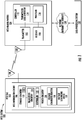
- the present invention concerns an RFID tag system 100 including an RFID tag 102 and an RFID reader/writer 104.
- the RFID tag 102 (also referred to as an RFID transponder) comprises an RFID antenna 120 and an RFID IC 106.
- the RFID antenna 120 receives incoming wireless signals and transmits wireless responses in the form of modulated radio frequency signals.
- the RFID reader/writer 104 wirelessly receives the responses transmitted from the RFID tag 102. In some scenarios, the RFID reader/writer 104 also transmits data and/or instructions to the RFID tag 102.
- RFID readers/writers are well known in the art, and therefore will not be described herein. Any known or to be known RFID reader/writer can be used herein without limitation.
- the RFID reader/writer 104 comprises an antenna 108, transmitter 110, controller 112 and a receiver 118.
- the controller 112 includes a transmission data generator 114 and a processor 116.
- Each of the listed components 104-116 is known in the art, and therefore is not described in detail herein. Still, it should be understood that these components facilitate: the wireless reception of response signals transmitted from the RFID tag 102; and/or the wireless transmission of data and/or instructions to the RFID tag 102.
- the RFID tag 102 is a passive device that obtains its operating power by harvesting energy from RF fields, magnetic fields, heat, movement and/or light.
- the incoming wireless signals serve to activate the RFID tag 102.
- the RFID tag 102 is activated in response to a detection of heat, movement and/or light as described in more detail below.
- the RFID IC 106 includes storage circuitry 122 to store a unique identifier of the RFID tag and/or other information.
- the storage circuitry 122 may include volatile memory and/or non-volatile memory.
- the memory can include, but is not limited to, a Random Access Memory ("RAM”), a Dynamic Random Access Memory (“DRAM”), a Static Random Access Memory (“SRAM”), a Read-Only Memory (“ROM”) and/or a flash memory.
- the memory may also comprise unsecure memory and/or secure memory.
- unsecure memory refers to memory configured to store data in a plain text form.
- secure memory refers to memory configured to store data in an encrypted form and/or memory having or being disposed in a secure or tamper-proof enclosure.
- the storage circuitry 122 comprises a computer-readable storage medium (not shown) on which is stored one or more sets of instructions 132 (e.g., software code) configured to implement one or more of the methodologies, procedures, or functions described herein.
- the instructions 132 can also reside, completely or at least partially, within the storage circuitry 122.
- the storage circuitry 122 also can constitute machine-readable media.
- machine-readable media refers to a single medium or multiple media (e.g., a flash memory, a RAM, a ROM, etc.) that store the one or more sets of instructions 132.
- machine-readable media also refers to any medium that is capable of storing, encoding or carrying a set of instructions 132 for execution by the RFID tag 102 and that cause the RFID tag 102 to perform any one or more of the methodologies of the present disclosure.
- the RFID IC 106 also includes receive circuitry 124 to receive incoming wireless signals through the antenna 120, transmit circuitry 124 to transmit the unique identifier and/or other information through the antenna 120, and power circuitry 126 to collect received energy from RF fields, magnetic fields, heat, movement and/or light. The collected energy is used to power the operations of the RFID tag 102.
- Receive and transmit circuitry is well known in the art, and therefore will not be described herein.
- the RFID IC 106 runs at a sub-threshold power or voltage level.
- sub-threshold means that a power level and/or voltage level falls at least one order of magnitude below a normal operating range for a given device.
- traditional processing systems normally operate at a power level at approximately 3 milli-Watts and/or a voltage level within 1.2 Volts to 3.6 Volts.
- the RFID IC 106 runs at a sub-threshold power level at approximately 3 micro-Watts and/or a voltage level within 200 milli-Volts to 600 milli-Volts.
- the RFID IC 106 may include a diode junction (or rectifier) to rectify an incoming signal and a transistor to switch the incoming signal to/from a transceiver.
- the input voltage needed to operate the diode junction and transistor is of a threshold voltage level (e.g., 1.5-3.0 Volts, 0.7 volts for the diode junction and 0.6 volts for the transistor).
- the input voltage needed to operate the diode junction and transistor of the RFID tag 102 is of a sub-threshold voltage level (e.g., 0.6 Volts) which is lower than the threshold voltage level (e.g., 1.5-3.0 Volts) of conventional RFID tags.
- the diode bridge employed by the present solution comprise low drop out diodes which enable active rectification at less than 20 milli-Volts compared to conventional diodes which enable rectification at 300-700 milli-Volts.
- the power circuitry 126 of the RFID IC 106 comprises low power voltage scavenging device(s) 130 and voltage converter(s) 128.
- the voltage scavenging device(s) 130 are generally configured to collect received energy from RF fields, magnetic fields, heat, movement and/or light. Accordingly, the voltage scavenging device(s) 130 include(s), but is(are) not limited to, low power RF field scavenging devices, low power magnetic field scavenging device, low power thermal scavenging devices, low power piezo devices, and low power photo voltaic scavenging devices. In all scenarios, the voltage scavenging device(s) 130 is(are) sized and shaped to minimize the amount of space taken up thereby on the RFID tag 102 having a height ⁇ approximately 2 inches and a width ⁇ approximately 3 inches.
- the voltage scavenging device(s) 130 can include, but is not limited to, a device having a part number BQ25570 which is available from Texas Instruments of Dallas, Texas. Additionally or alternatively, the voltage scavenging device(s) 130 can include, but is not limited to, that shown in FIG. 2 and discussed below.
- the architecture of FIG. 2 is applicable to RF scenarios and/or other scenarios in which the input voltage from the antenna 120 is Alternating Current ("AC").
- the architecture of FIG. 2 can be modified for applicability in scenarios in which the input voltage from the antenna 120 is Direct Current ("DC").
- DC Direct Current
- full wave rectifier 252 can be eliminated from the voltage scavenging device 130 in the DC scenarios.
- the voltage converter(s) 128 comprises an electric power converter which changes the output voltage of an electrical power source, such as a low power voltage scavenging device(s) 130.
- the voltage converter(s) 128 includes, but is not limited to, an inverter, a semiconductor switch (e.g., a transistor), passive components (e.g., inductors, capacitors, resistors, and/or diodes), and/or a transformer to change the voltage of AC power.
- the voltage converter(s) 128 raise(s) or lower(s) the level of an input voltage received from the voltage scavenging device(s) 130 to the sub-threshold voltage level (e.g., 0.6 Volts).
- the input voltage e.g., 30 millivolts or 0.5 Volts
- the sub-threshold voltage level e.g., 0.6 Volts
- the input voltage e.g., > 0.6 Volt
- the sub-threshold voltage level e.g., 0.6 Volts.
- Reducing the required operating voltage of the RFID tag 102 means a lower field level (volts per meter) is required for a given antenna size.
- running the RFID tag 102 at a sub-threshold power or voltage level means the RFID IC 106 operates more slowly than normal super-threshold ICs, but runs at 100-1000 times lower current.
- operating the RFID tag 102 at sub-threshold levels allows the output antenna power of the RFID reader/writer 104 to be significantly lowered as compared to conventional non sub-threshold based RFID systems.
- the RFID IC 106 can be created by (1) changing the processing parameters for the mask sets during fabrication, (2) changing the implantation rules for dopants and/or (3) changing processing parameters. However, the RFID IC 106 can be made on regular CMOS fabrication lines without affecting the normal operation of the line. This allows most FAB lines to create sub-threshold electronics on their standard lines using the normal mask processes used in fabrication.
- the advantages of running the RFID IC 106 at a sub-threshold power or voltage level are substantial.
- the RFID IC 106 is ideally suited to working with energy harvesting devices which are notorious for supplying very low power and voltages.
- the RFID IC's 106 use with resulting inlays or RFID tags. Since the operating power of the RFID IC 106 is substantially reduced, the read range for a given sized inlay is ten to fifteen times larger as compared to that of conventional RFID tags. For example, an inlay that is only one centimeter long can operate like a conventional inlay that is ten to fifteen centimeters long.
- the size of the antenna 120 can be reduced as compared to that of conventional RFID tags, while still maintaining the larger read range.
- the size reductions of the inly and antenna provide significant advantages when placing the RFID IC 106 in/on packaging or incorporating the RFID IC 106 into a swing ticket or price label.
- the voltage scavenging device 130 is generally configured to derive energy from an external source to power other electronic components internal to RFID tag 102.
- the voltage scavenging device 130 comprises a switch 250, a full wave rectifier 252, an energy harvester power manager 258, and an energy storage device 262.
- the voltage scavenging device 130 may also comprise matching circuits (not shown) to optimize a power transfer from an antenna 120 of the RFID tag 102 and/or to impedance match the antenna to a transceiver 124 of the RFID tag 102.
- Antenna 120 can include any known or to be known antenna.
- the antenna comprises an antenna described in U.S. Patent Publication No. 2015/0054696 .
- the present invention is not limited in this regard.
- the energy storage device 262 comprises a super capacitor.
- the switch 250 includes a Field Effect Transistor ("FET”) switch.
- the FET switch may comprise a Heterostructure FET (“HFET”) which without applied power directly couples the antenna 120 to the voltage scavenging device electronics.
- HFET Heterostructure FET
- RF energy is emitted within a surrounding environment from equipment disposed within a facility (e.g., at an access point of a restricted area).
- the voltage scavenging device 130 charges up the energy storage device 262 (e.g., a super capacitor) to a pre-determined voltage level.
- the switch 250 is normally in a position which provides an electric connection or closed circuit between the antenna 120 and the full wave rectifier 252, as shown in FIG. 2 .
- the switch 250 In the absence of an energy source (and hence the application of a voltage to power the switch), the switch 250 is in an indeterminate state causing the RF signal to bleed through both channels thereof, but with significantly reduced output.
- the voltage output is sufficient to turn on or enable the voltage scavenging device electronics 252, 258, 262 such that RF energy can be captured thereby.
- the captured RF energy is passed through the switch 250 by virtue of the switches characteristics described above.
- the energy harvester power manager 258 converts the received RF energy into direct current for generating electric power.
- the electric power is supplied to the energy storage device 262 (e.g., a super capacitor) for charging the same to the pre-determined voltage level.
- a graph is provided in FIG. 3 that is useful for understanding the charging of an energy storage device, such as a capacitor.
- the voltage of the energy storage device 262 is sufficient to power up the components 124, 132 of the RFID IC 106 as the RFID tag 102 passes through or within the RF field generated by the external device (e.g., a wireless edge device located at an entryway of a facility).
- the controller 132 When the energy storage device 262 is charged to the pre-determined voltage level, power is supplied from the energy storage device 262 to the controller 132 via the energy harvester power manager 258.
- the controller 132 generates and sends a switch control signal 266 to the switch 250.
- the switch control signal 266 includes a command to cause the switch 250 to change positions.
- the switch 250 is disconnected from the voltage scavenging device 130, whereby an open circuit is formed between the antenna 120 and the full wave rectifier 252.
- the switch 250 is connected to the transceiver 124 so as to allow communication of information from the RFID tag 102 to a nearby communications device.
- the controller 132 initiates communications with the external device such that certain information is passed from the RFID tag 102 to the external device.
- the external device processes the received information for pre-specified purposes (e.g., authentication of a user, verification of a successful purchase, tracking of an item, etc.).
- the antenna 120 of the RFID tag 102 may comprise a directional antenna arranged to point away from an item, article, object or person when the RFID tag 102 is attached thereto.
- the antenna 120 is coupled to Short Range Communication ("SRC") components 122, 124, 132 of the RFID IC 106 implementing SRC technology.
- SRC technology includes, but is not limited to, RF technology which uses RF electromagnetic fields to identify RFID tags, items, articles, objects or persons when they come close to the RFID reader/writer 104. Accordingly, SRC components facilitate communication of at least one unique identifier and/or other information to the RFID reader/writer 104 via SRC reply signals in response to interrogation signals sent from the RFID reader/writer 104. The unique identifier is then used by the RFID reader/writer 104 to at least automatically identify the RFID tag, item, article, object or person.
- Method 400 begins with step 402 and continues with step 404 where RF energy is emitted within a surrounding environment from equipment disposed at an access point of a restricted area.
- step 406 the RFID tag enters into the RF field at an operating frequency of an antenna of the RFID tag.
- RF energy is captured by the RFID tag as shown by step 408.
- the captured RF energy is passed through a switch (e.g., switch 250 of FIG. 2 ) of the RFID tag, as shown by step 410.
- the switch is normally in a position which provides an electrical connection or closed circuit between an antenna (e.g., antenna 120 of FIG. 1 ) and a full wave rectifier (e.g., full wave rectifier 252 of FIG. 2 ) of the RFID tag.
- An energy harvester power manager e.g., energy harvester power manager 258 of FIG. 2
- step 412 to convert the RF energy into direct current for generating electric power.
- the electric power is supplied to an energy storage device (e.g., energy storage device 262 of FIG. 2 ) of the RFID tag in step 414 for charging the same to a pre-determined voltage level. If the voltage of the energy storage device (e.g., a capacitor) is not equal to or greater than the pre-determined voltage level [416:NO], then method 400 returns to step 414 so that the energy storage device continues to be charged.
- the voltage of the energy storage device e.g., a capacitor
- steps 418-422 are performed. These steps involve: supplying power from the energy storage device to a controller (e.g., controller 132 of FIG. 1 ) of the RFID tag via the energy harvester power manager and/or voltage converter; generating and sending a switch control signal from the controller to the switch so as to cause the switch to change positions so as to be disconnected from the antenna and connected to a transceiver of the RFID tag; and communicating information from the RFID tag to an external device.
- step 424 is performed where method 400 ends or other processing is performed.
- Method 500 begins with step 502 and continues with step 504 where a voltage scavenging device (e.g., voltage scavenging device 130 of FIGS. 1-2 ) of an RFID tag (e.g., RFID tag 102 of FIG. 1 ) collects energy. The collected energy is then stored in an energy storage device (e.g., energy storage device 262 of FIG. 2 ) of the RFID tag. When the energy storage device charges to an operating voltage level of the SRC components (e.g., components 122, 124, 132 of FIG.
- an operating voltage level of the SRC components e.g., components 122, 124, 132 of FIG.
- step 510 is performed where the RFID tag is transitioned from its energy harvesting mode to its communication mode.
- step 512 is performed.
- Step 512 involves transmitting an SRC signal from the RFID tag.
- the SRC signal includes, but is not limited to, a unique identifier and/or first information indicating a rate of change of the charging voltage of the energy storage device.
- the SRC signal is then received in step 514 at an antenna (e.g., antenna 108 of FIG. 1 ) coupled to an RFID reader/writer (e.g., RFID reader/writer 104 of FIG. 1 ).
- step 516 the direction and/or speed/velocity of motion of the RFID tag is detected.
- Techniques for detecting the direction and/or speed/velocity of motion are well known in the art. Any known or to be known technique can be used herein without limitation.
- step 518 second information is communicated to the RFID reader/writer specifying the detected direction and/or speed/velocity of the RFID tag's motion.
- the RFID reader/writer then communicates the following information to a data processing system (e.g., data processing system 152 of FIG. 1 ): the unique identifier, a time stamp, the first information; and/or the second information (as shown by step 520 ).
- a data processing system e.g., data processing system 152 of FIG. 1
- step 522 operations are performed in step 522 to determine whether or not a person is attempting to enter or exit the restricted area using the information received in previous step 520. For example, if the received information indicates that the RFID tag is traveling towards an entrance in a first direction, then a determination is made that the person desires to enter the restricted area via an access point (e.g., a doorway). In contrast, if the received information indicates that the RFID tag is traveling towards an exit in a second direction opposed from the first direction, then a determination is made that the person desired to exit the restricted area via the access point. If the received information indicates that the RFID tag is traveling away from the entrance, then a determination is made that the person is not trying to enter the restricted area.
- an access point e.g., a doorway
- the data processing system additionally or alternatively analyzes patterns of motion defined by the received information to determine whether or not the person desires to enter or exit the access point.
- step 524 After completing step 522, method 500 continues with a decision step 524. If it is determined that the person does not want to enter or exit the restricted area [524:NO], then step 526 is performed where the following information is logged in a data store: the unique identifier; a time stamp; the first information; the second information; and/or the third information indicating the results of the operations performed in previous step 522. Subsequently, step 536 is performed where method 500 ends or other processing is performed.
- step 530 is performed where the data processing system performs actions to cause actuation of a door opening actuator (e.g., a lock).
- steps 532-534 are performed to log the following information: the unique identifier; the time stamp; the first information; the second information; the third information; and/or the fourth information indicating that the person entered or exited the restricted area at a particular time.
- step 536 is performed where method 500 ends or other processing is performed.
Landscapes
- Engineering & Computer Science (AREA)
- Physics & Mathematics (AREA)
- Computer Hardware Design (AREA)
- Microelectronics & Electronic Packaging (AREA)
- Electromagnetism (AREA)
- General Physics & Mathematics (AREA)
- Theoretical Computer Science (AREA)
- Acoustics & Sound (AREA)
- Power Engineering (AREA)
- Computer Security & Cryptography (AREA)
- General Engineering & Computer Science (AREA)
- Computer Networks & Wireless Communication (AREA)
- Near-Field Transmission Systems (AREA)
Claims (13)
- Procédé d'utilisation d'un transpondeur RFID d'identification par radiofréquence, le transpondeur RFID comprenant une antenne RFID (120) et un contrôleur (132), le procédé comprenant :
la réalisation d'opérations de récupération d'énergie par un dispositif de récupération de tension (130) du transpondeur RFID, le dispositif de récupération de tension (130) comprenant un commutateur (250), un redresseur pleine-onde (252), un gestionnaire de puissance de récupérateur d'énergie (258), et un dispositif de stockage d'énergie (262), pour récupérer l'énergie d'un champ de radiofréquence RF, d'un champ magnétique, de la chaleur, de la lumière ou du mouvement du transpondeur RFID ; le procédé étant caractérisé par :le chargement du dispositif de stockage d'énergie (262) à un niveau de tension prédéterminé à l'entrée dans un champ RF qui correspond à une fréquence d'antenne de l'antenne (120) du transpondeur RFID ;le changement de position d'un commutateur (250) qui est normalement dans une position qui assure une connexion électrique ou un circuit fermé entre l'antenne (120) du transpondeur RFID et le redresseur pleine-onde (252) quand le dispositif de stockage d'énergie (262) est chargé au niveau de tension prédéterminé ;l'augmentation ou la diminution, par un convertisseur de tension (128) du transpondeur RFID, un niveau de tension d'un signal reçu du dispositif de récupération de tension (130) à un niveau de tension de sous-seuil qui est d'au moins un ordre de magnitude inférieur à une plage de fonctionnement normale pour le transpondeur RFID ; et l'alimentation d'une tension de fonctionnement au niveau de tension de sous-seuil à au moins un circuit émetteur-récepteur du transpondeur RFID. - Procédé selon la revendication 1, dans lequel la plage de fonctionnement normal pour un niveau de tension est de 1,2 Volt à 3,6 Volts et/ou le niveau de tension de sous-seuil est de 200 millivolts à 600 millivolts.
- Procédé selon la revendication 1, dans lequel le niveau de tension est accru au niveau de tension de sous-seuil quand l'énergie est recueillie du champ RF, du champ magnétique, de la chaleur ou de la lumière et/ou le niveau de tension est réduit au niveau de tension de sous-seuil quand l'énergie est recueillie de la lumière ou du mouvement du transpondeur RFID.
- Procédé selon la revendication 1, dans lequel les opérations de récupération de l'énergie comprennent :la capture de l'énergie RF émise dans un environnement de l'équipement ; le passage de l'énergie RF à travers le commutateur (252) qui est normalement dans la position qui assure une connexion électrique entre une antenne du transpondeur RFID et le redresseur pleine-onde (252) du transpondeur RFID ;la conversion de l'énergie RF en courant continu pour générer une énergie électrique ;l'alimentation de l'énergie électrique au dispositif de stockage d'énergie (262) du transpondeur RFID pour charger le dispositif de stockage d'énergie (262) au niveau de tension prédéterminé ; etl'alimentation de l'énergie du dispositif de stockage d'énergie (262) au contrôleur (132) du transpondeur RFID quand un niveau de tension du dispositif de stockage d'énergie (262) est supérieur ou égal au niveau de tension prédéterminé.
- Procédé selon la revendication 4, comprenant en outre la génération et l'envoi d'un signal de commande du commutateur du contrôleur au commutateur (250) pour que le commutateur (250) change de position de telle manière que ce commutateur (250) soit débranché de l'antenne et raccordé à un émetteur-récepteur (124) du transpondeur RFID.
- Procédé selon la revendication 4, comprenant en outre la communication d'informations du transpondeur RFID à un appareil externe.
- Procédé selon la revendication 6, dans lequel les informations sont utiles pour déterminer si l'accès à une zone d'accès restreint doit être accordé ou refusé à une personne.
- Transpondeur RFID d'identification par radiofréquence, comprenant :
une antenne RFID (120) et un contrôleur (132), un dispositif de récupération de tension (130) qui réalise des opérations de récupération d'énergie pour recueillir l'énergie d'un champ de radiofréquence RF, d'un champ magnétique, de la chaleur, de la lumière ou du mouvement du transpondeur RFID ; le transpondeur RFID étant caractérisé en ce que :
le dispositif de récupération de tension (130) comprend un commutateur (250), un redresseur pleine-onde (252), un gestionnaire de puissance de récupérateur d'énergie (258), et un dispositif de stockage d'énergie (262) ; le contrôleur (132) déplace un commutateur (250) qui est normalement dans une position qui assure une connexion électrique ou un circuit fermé entre l'antenne (120) du transpondeur RFID et le redresseur pleine-onde (252) quand le dispositif de stockage d'énergie (262) est chargé au niveau de tension prédéterminé ; un convertisseur de tension qui augmente ou réduit un niveau de tension d'un signal reçu du dispositif de récupération de tension (130) à un niveau de tension de sous-seuil qui est au moins d'un ordre de magnitude inférieur à une plage de fonctionnement normal pour le transpondeur RFID ; et un circuit émetteur-récepteur alimenté par une tension de fonctionnement au niveau de tension de sous-seuil. - Transpondeur RFID selon la revendication 8, dans lequel la plage de fonctionnement normal pour un niveau de tension est de 1,2 Volts à 3,6 Volts et/ou le niveau de tension de sous-seuil est de 200 millivolts à 600 millivolts.
- Transpondeur RFID selon la revendication 8, dans lequel le niveau de tension est accru au niveau de tension de sous-seuil quand l'énergie est récupérée du champ RF, du champ magnétique, de la chaleur ou de la lumière et/ou le niveau de tension est réduit au niveau de tension de sous-seuil quand l'énergie est récupérée de la lumière ou du mouvement du transpondeur RFID.
- Transpondeur RFID selon la revendication 8, dans lequel les opérations de récupération d l'énergie comprennent :la capture de l'énergie RF émise dans un environnement de l'équipement ; le passage de l'énergie RF à travers le commutateur (252) qui est normalement dans la position qui assure une connexion électrique entre une antenne du transpondeur RFID et le redresseur pleine-onde (252) du transpondeur RFID ;la conversion de l'énergie RF en courant continu pour générer une énergie électrique ;l'alimentation de l'énergie électrique au dispositif de stockage d'énergie (262) du transpondeur RFID pour charger le dispositif de stockage d'énergie (262) au niveau de tension prédéterminé ; etl'alimentation de l'énergie du dispositif de stockage d'énergie (262) au contrôleur (132) du transpondeur RFID quand un niveau de tension du dispositif de stockage d'énergie (262) est supérieur ou égal au niveau de tension prédéterminé.
- Le transpondeur RFID selon la revendication 11, dans lequel le contrôleur (132) génère et envoie un signal de commande au commutateur (250) pour que le commutateur (250) change de position de telle manière que ce commutateur (250) soit déconnecté de l'antenne (120) et connecté à un émetteur-récepteur (124) du transpondeur RFID.
- Transpondeur RFID selon la revendication 12, dans lequel le circuit émetteur-récepteur communique des informations à un appareil externe quand la tension de fonctionnement est fournie au niveau de tension de sous-seuil.
Applications Claiming Priority (2)
| Application Number | Priority Date | Filing Date | Title |
|---|---|---|---|
| US201462086241P | 2014-12-02 | 2014-12-02 | |
| PCT/US2015/063526 WO2016090043A1 (fr) | 2014-12-02 | 2015-12-02 | Étiquettes d'identification par radiofréquence (rfid) passives ayant des circuits intégrés utilisant une technologie de sous-seuil |
Publications (2)
| Publication Number | Publication Date |
|---|---|
| EP3227835A1 EP3227835A1 (fr) | 2017-10-11 |
| EP3227835B1 true EP3227835B1 (fr) | 2020-09-16 |
Family
ID=54884421
Family Applications (1)
| Application Number | Title | Priority Date | Filing Date |
|---|---|---|---|
| EP15813207.6A Active EP3227835B1 (fr) | 2014-12-02 | 2015-12-02 | Étiquettes d'identification par radiofréquence (rfid) passives ayant des circuits intégrés utilisant une technologie de sous-seuil |
Country Status (8)
| Country | Link |
|---|---|
| US (1) | US9589224B2 (fr) |
| EP (1) | EP3227835B1 (fr) |
| KR (1) | KR102495131B1 (fr) |
| CN (1) | CN107209869B (fr) |
| AU (1) | AU2015358525B2 (fr) |
| CA (1) | CA2972425C (fr) |
| ES (1) | ES2833015T3 (fr) |
| WO (1) | WO2016090043A1 (fr) |
Families Citing this family (28)
| Publication number | Priority date | Publication date | Assignee | Title |
|---|---|---|---|---|
| US10211679B1 (en) * | 2015-08-31 | 2019-02-19 | Spatiallink Corporation | Hybrid source of energy supply scheme for internet of things system on chip |
| US11048893B2 (en) * | 2016-05-25 | 2021-06-29 | William Marsh Rice University | Methods and systems related to remote measuring and sensing |
| US9911075B1 (en) * | 2016-09-01 | 2018-03-06 | Nxp B.V. | RFID transponder and method for supplying energy thereto |
| AU2018325468B2 (en) * | 2017-09-01 | 2023-09-07 | Powercast Corporation | Methods, systems, and apparatus for automatic RF power transmission and single antenna energy harvesting |
| US10970725B2 (en) | 2017-11-29 | 2021-04-06 | Universal Studios LLC | System and method for crowd management and maintenance operations |
| US10916059B2 (en) | 2017-12-06 | 2021-02-09 | Universal City Studios Llc | Interactive video game system having an augmented virtual representation |
| US10653957B2 (en) | 2017-12-06 | 2020-05-19 | Universal City Studios Llc | Interactive video game system |
| CN109900268A (zh) * | 2017-12-07 | 2019-06-18 | 中国科学院深圳先进技术研究院 | 一种无源室内定位节点装置及相应的室内定位系统 |
| CA3020322C (fr) | 2017-12-13 | 2025-09-23 | Universal City Studios Llc | Sytemes et methodes de detection du seuil d'un dispositif sans fil |
| US10603564B2 (en) | 2018-01-03 | 2020-03-31 | Universal City Studios Llc | Interactive component for an amusement park |
| US10360419B1 (en) | 2018-01-15 | 2019-07-23 | Universal City Studios Llc | Interactive systems and methods with tracking devices |
| US10614271B2 (en) | 2018-01-15 | 2020-04-07 | Universal City Studios Llc | Interactive systems and methods |
| US10818152B2 (en) | 2018-01-15 | 2020-10-27 | Universal City Studios Llc | Interactive systems and methods with feedback devices |
| US10699084B2 (en) | 2018-01-15 | 2020-06-30 | Universal City Studios Llc | Local interaction systems and methods |
| US10537803B2 (en) | 2018-01-18 | 2020-01-21 | Universal City Studios Llc | Interactive gaming system |
| US10845975B2 (en) | 2018-03-29 | 2020-11-24 | Universal City Studios Llc | Interactive animated character head systems and methods |
| ES2727150A1 (es) * | 2018-04-13 | 2019-10-14 | Yocto Tech S L | Tag electrónico semiactivo autoalimentado con capacidad de procesamiento autónomo y su procedimiento de comunicación |
| WO2019224575A1 (fr) | 2018-05-22 | 2019-11-28 | Tyco Fire & Security Gmbh | Étiquette souple allongée |
| US12223814B2 (en) | 2019-09-16 | 2025-02-11 | Sensormatic Electronics, LLC | Security tag for textiles using conductive thread |
| US11443160B2 (en) | 2019-09-18 | 2022-09-13 | Sensormatic Electronics, LLC | Systems and methods for laser tuning and attaching RFID tags to products |
| US10970613B1 (en) | 2019-09-18 | 2021-04-06 | Sensormatic Electronics, LLC | Systems and methods for providing tags adapted to be incorporated with or in items |
| US12101138B2 (en) * | 2019-09-19 | 2024-09-24 | Sensormatic Electronics, LLC | Self-detaching anti-theft device using direct and harvested resonant energy |
| US11055588B2 (en) | 2019-11-27 | 2021-07-06 | Sensormatic Electronics, LLC | Flexible water-resistant sensor tag |
| US12524640B2 (en) | 2019-11-27 | 2026-01-13 | Sensormatic Electronics, LLC | Flexible water-resistant sensor tag |
| US11755874B2 (en) | 2021-03-03 | 2023-09-12 | Sensormatic Electronics, LLC | Methods and systems for heat applied sensor tag |
| PL4075334T3 (pl) | 2021-04-14 | 2024-08-12 | Yocto Technologies, S.L. | Sposób bezprzewodowego odbierania i przesyłania promieniowania elektromagnetycznego i służące do tego urządzenie elektroniczne |
| US11869324B2 (en) | 2021-12-23 | 2024-01-09 | Sensormatic Electronics, LLC | Securing a security tag into an article |
| US12536401B2 (en) | 2022-08-31 | 2026-01-27 | Sensormatic Electronics, LLC | Security tag |
Family Cites Families (70)
| Publication number | Priority date | Publication date | Assignee | Title |
|---|---|---|---|---|
| DE69424704T2 (de) | 1993-03-17 | 2000-09-28 | Seiko Epson Corp., Tokio/Tokyo | Antenne und diese enthaltendes Gerät |
| US5763868A (en) | 1994-07-25 | 1998-06-09 | Dai Nippon Printing Co., Ltd. | Optical card |
| US5947369A (en) | 1995-09-21 | 1999-09-07 | Temtec, Inc. | Electronic time badge |
| US6395373B2 (en) | 1998-02-11 | 2002-05-28 | Avery Dennison Corporation | Label/tag with embedded signaling device and method and apparatus for making and using |
| GB9917678D0 (en) | 1999-07-29 | 1999-09-29 | Koninkl Philips Electronics Nv | Body-worn personal communications apparatus |
| US6720877B2 (en) | 2001-03-29 | 2004-04-13 | Sensormatic Electronics Corporation | Manufacturing methods for magnetomechanical electronic article surveillance markers |
| DE60132662T2 (de) | 2001-07-03 | 2009-02-05 | Barco N.V. | Verfahren und Einrichtung zur Echtzeitkorrektur eines Bildes |
| US6590540B1 (en) | 2002-01-31 | 2003-07-08 | The United States Of America As Represented By The Secretary Of The Navy | Ultra-broadband antenna incorporated into a garment |
| US6888502B2 (en) | 2002-03-05 | 2005-05-03 | Precision Dynamics Corporation | Microstrip antenna for an identification appliance |
| US6980087B2 (en) | 2003-06-04 | 2005-12-27 | Pitney Bowes Inc. | Reusable electronic tag for secure data accumulation |
| US7774242B2 (en) | 2004-03-17 | 2010-08-10 | Sap Ag | Proximity sensing |
| JP2006295234A (ja) | 2005-04-05 | 2006-10-26 | Toshiba Corp | 認証システム、認証方法および入退場管理システム |
| WO2006116168A2 (fr) * | 2005-04-21 | 2006-11-02 | Univeristy Of Pittsburgh-Of The Commonwealth System Of Higher Education | Procedes et appareil permettant de reduire la consommation d'energie d'un transpondeur actif |
| WO2007014053A2 (fr) * | 2005-07-22 | 2007-02-01 | Nanopower Technologies, Inc. | Circuits integres d'etiquette rfid a sensibilite elevee |
| US20070182559A1 (en) | 2005-09-15 | 2007-08-09 | Zih Corp. | Rfid antenna on multiple sides of 3-d packaging |
| US8552597B2 (en) * | 2006-03-31 | 2013-10-08 | Siemens Corporation | Passive RF energy harvesting scheme for wireless sensor |
| US8323189B2 (en) | 2006-05-12 | 2012-12-04 | Bao Tran | Health monitoring appliance |
| US7450077B2 (en) | 2006-06-13 | 2008-11-11 | Pharad, Llc | Antenna for efficient body wearable applications |
| US20080055045A1 (en) | 2006-08-31 | 2008-03-06 | 3M Innovative Properties Company | Rfid tag including a three-dimensional antenna |
| US7696882B1 (en) | 2007-02-21 | 2010-04-13 | Impinj, Inc. | Reading codes of RFID tags incoming at premises and removing them later as they exit |
| US20140375429A1 (en) * | 2007-07-27 | 2014-12-25 | Lucomm Technologies, Inc. | Systems and methods for object localization and path identification based on rfid sensing |
| US20090121931A1 (en) | 2007-11-12 | 2009-05-14 | Katz Daniel A | Wrist Worn Communication Device coupled with Antenna Extendable by the Arm |
| GB0724705D0 (en) | 2007-12-19 | 2008-01-30 | Rhodes Mark | Antenna integrated in diver's clothing |
| US7847697B2 (en) | 2008-02-14 | 2010-12-07 | 3M Innovative Properties Company | Radio frequency identification (RFID) tag including a three-dimensional loop antenna |
| US8674808B2 (en) * | 2008-02-29 | 2014-03-18 | Nokia Corporation | Interrogation of RFID communication units |
| KR100958239B1 (ko) * | 2008-03-10 | 2010-05-17 | 엘에스산전 주식회사 | Rfid 태그 |
| EP2265331B2 (fr) | 2008-03-28 | 2025-03-19 | Cochlear Limited | Antenne pour dispositifs placés derrière l'oreille (bte) |
| CN101604399A (zh) * | 2008-06-12 | 2009-12-16 | 苏州工业园区优频科技有限公司 | 有源射频识别标签 |
| US20090322513A1 (en) | 2008-06-27 | 2009-12-31 | Franklin Dun-Jen Hwang | Medical emergency alert system and method |
| JP5377640B2 (ja) | 2008-07-23 | 2013-12-25 | キャディ サイエンティフィック プライベート リミテッド | サブジェクトの位置を決定するシステムおよび方法 |
| JP5432983B2 (ja) | 2009-03-09 | 2014-03-05 | パナソニック株式会社 | 入退検出装置、監視装置及び入退検出方法 |
| US9024761B2 (en) * | 2009-03-17 | 2015-05-05 | Taiwan Semiconductor Manufacturing Company, Ltd. | System and method for persistent ID flag for RFID applications |
| CA2759927C (fr) | 2009-04-22 | 2017-10-24 | Franwell, Inc. | Systeme rfid pouvant etre porte |
| EP2441063B1 (fr) | 2009-06-12 | 2015-03-11 | Ecolab USA Inc. | Surveillance de l'observance de l'hygiène des mains |
| US8267325B2 (en) | 2009-08-05 | 2012-09-18 | Avery Dennison Corporation | Wristband with elastic portion and inelastic portion containing a RFID inlay |
| EP2504796B1 (fr) | 2009-11-25 | 2015-09-16 | Avery Dennison Corporation | Etiquette d'habillement rfid destinée à être utilisée dans un traitement industriel et un traitement post-soin |
| WO2011066215A1 (fr) * | 2009-11-30 | 2011-06-03 | Corning Incorporated | Verrouillage de condition rfid |
| US8736513B2 (en) | 2010-01-27 | 2014-05-27 | Sarantel Limited | Dielectrically loaded antenna and radio communication apparatus |
| US20110181399A1 (en) * | 2010-01-28 | 2011-07-28 | Dvm Systems, Llc | Energy harvesting with rfid tags |
| WO2011109005A1 (fr) | 2010-03-02 | 2011-09-09 | Utc Fire & Security Corporation | Système d'authentification unifié |
| US9477922B2 (en) | 2010-09-01 | 2016-10-25 | Quake Global, Inc. | UHF RFID wristband with a long read range |
| US8646695B2 (en) | 2010-10-01 | 2014-02-11 | Disney Enterprises, Inc. | Combined HF and UHF RFID device |
| US9689955B2 (en) | 2011-02-24 | 2017-06-27 | Corvus Technologies Corp | Ranging system using active radio frequency (RF) nodes |
| CH704583B1 (fr) | 2011-03-03 | 2016-03-15 | Winwatch Ip Ltd | Etiquette radiofréquence, et composants d'une montre et montre-bracelet équipés d'une telle étiquette radiofréquence. |
| US8917214B2 (en) | 2011-03-16 | 2014-12-23 | Avery Dennison Corporation | Dual band RFID device and method of formulation |
| US20140077929A1 (en) | 2012-03-08 | 2014-03-20 | Unikey Technologies, Inc. | Wireless access control system and related methods |
| US8497808B2 (en) | 2011-04-08 | 2013-07-30 | Wang Electro-Opto Corporation | Ultra-wideband miniaturized omnidirectional antennas via multi-mode three-dimensional (3-D) traveling-wave (TW) |
| US20120286927A1 (en) | 2011-05-12 | 2012-11-15 | Andreas Hagl | Wake Channel Indication for Passive Entry System |
| EP2817788A2 (fr) | 2012-02-24 | 2014-12-31 | Identive Group, Inc. | Procédé et système de fourniture des services d'identité, d'authentification et d'accès |
| ITMI20120310A1 (it) * | 2012-02-29 | 2013-08-30 | St Microelectronics Srl | Regolatore di tensione per dispositivi elettronici contact-less |
| US20130249301A1 (en) * | 2012-03-21 | 2013-09-26 | Disney Enterprises, Inc., A Delaware Corporation | System And Method For Powering An RFID Module Using An Energy Harvesting Element |
| US9564682B2 (en) | 2012-07-11 | 2017-02-07 | Digimarc Corporation | Body-worn phased-array antenna |
| US20140159975A1 (en) | 2012-08-14 | 2014-06-12 | AMI Research & Development, LLC | Wideband compact dipole manpack antenna |
| KR101694519B1 (ko) * | 2012-11-16 | 2017-01-10 | 한국전자통신연구원 | 센서 태그 및 그를 이용한 서비스 제공 방법 |
| US9110897B2 (en) * | 2012-11-16 | 2015-08-18 | Electronics And Telecommunications Research Institute | Sensor tag and method of providing service using the same |
| WO2014113882A1 (fr) | 2013-01-28 | 2014-07-31 | Spielo International Canada Ulc | Système informatique et procédé pour le géorepérage et le contrôle d'accès à l'intérieur des bâtiments |
| EP2765650A1 (fr) | 2013-02-08 | 2014-08-13 | Nxp B.V. | Antenne de prothèse auditive |
| US9557719B2 (en) | 2013-02-26 | 2017-01-31 | Honeywell International Inc. | Access control system using smart phone |
| US10229548B2 (en) | 2013-03-15 | 2019-03-12 | The Chamberlain Group, Inc. | Remote guest access to a secured premises |
| US20140354494A1 (en) | 2013-06-03 | 2014-12-04 | Daniel A. Katz | Wrist Worn Device with Inverted F Antenna |
| BR112015032345B8 (pt) | 2013-06-24 | 2022-08-30 | Avery Dennison Corp | Etiquetas de mercadoria usando um condutor de antena |
| US9343800B2 (en) | 2013-08-09 | 2016-05-17 | Motorola Solutions, Inc. | Flexible mounting apparatus for mounting an antenna |
| WO2015023737A1 (fr) | 2013-08-15 | 2015-02-19 | Unikey Technologies, Inc. | Système sans fil de contrôle d'accès et procédés apparentés |
| US9478852B2 (en) | 2013-08-22 | 2016-10-25 | The Penn State Research Foundation | Antenna apparatus and communication system |
| EP3075085B1 (fr) | 2013-11-27 | 2020-01-08 | Shenzhen Goodix Technology Co., Ltd. | Dispositifs de communication portatifs pour des transactions et des communications sécurisées |
| US9361564B2 (en) * | 2013-12-02 | 2016-06-07 | Qualcomm Technologies International, Ltd. | Protection of an NFC or RFID radio in the presence of strong electromagnetic fields |
| CN103714378B (zh) * | 2014-01-08 | 2016-09-07 | 卓捷创芯科技(深圳)有限公司 | 一种无源射频标签的智能化能量管理系统与能量管理方法 |
| US20150264431A1 (en) | 2014-03-14 | 2015-09-17 | Aliphcom | Presentation and recommendation of media content based on media content responses determined using sensor data |
| CA2892113C (fr) | 2014-05-20 | 2022-11-08 | Tyco Safety Products Canada Ltd. | Systeme de securite a niveau d'acces double et methode |
| US9811955B2 (en) | 2014-06-25 | 2017-11-07 | Amazon Technologies, Inc. | Wearable RFID devices with manually activated RFID tags |
-
2015
- 2015-12-02 EP EP15813207.6A patent/EP3227835B1/fr active Active
- 2015-12-02 WO PCT/US2015/063526 patent/WO2016090043A1/fr not_active Ceased
- 2015-12-02 ES ES15813207T patent/ES2833015T3/es active Active
- 2015-12-02 CN CN201580075126.8A patent/CN107209869B/zh active Active
- 2015-12-02 AU AU2015358525A patent/AU2015358525B2/en active Active
- 2015-12-02 CA CA2972425A patent/CA2972425C/fr active Active
- 2015-12-02 US US14/956,433 patent/US9589224B2/en active Active
- 2015-12-02 KR KR1020177018342A patent/KR102495131B1/ko active Active
Non-Patent Citations (1)
| Title |
|---|
| None * |
Also Published As
| Publication number | Publication date |
|---|---|
| ES2833015T3 (es) | 2021-06-14 |
| US20160155040A1 (en) | 2016-06-02 |
| CA2972425A1 (fr) | 2016-06-09 |
| WO2016090043A1 (fr) | 2016-06-09 |
| CA2972425C (fr) | 2023-04-25 |
| CN107209869A (zh) | 2017-09-26 |
| EP3227835A1 (fr) | 2017-10-11 |
| AU2015358525A1 (en) | 2017-07-13 |
| US9589224B2 (en) | 2017-03-07 |
| KR20170102478A (ko) | 2017-09-11 |
| KR102495131B1 (ko) | 2023-02-01 |
| CN107209869B (zh) | 2020-10-27 |
| AU2015358525B2 (en) | 2020-04-30 |
Similar Documents
| Publication | Publication Date | Title |
|---|---|---|
| EP3227835B1 (fr) | Étiquettes d'identification par radiofréquence (rfid) passives ayant des circuits intégrés utilisant une technologie de sous-seuil | |
| US9831724B2 (en) | Access control system using a wearable access sensory implementing an energy harvesting technique | |
| JP7460808B2 (ja) | 伴侶動物の健康モニタリングシステム | |
| US8810373B2 (en) | Active energy harvesting for radio-frequency identification devices | |
| EP1844299B1 (fr) | Reseau de circuits de detection, dispositif de commande pour faire fonctionner un reseau de circuits de detection et systeme de detection | |
| US8593260B2 (en) | System and method for varying response amplitude of radio transponders | |
| KR20130038553A (ko) | 위치 인식 시스템에서 사물 위치 인식 장치 및 방법 | |
| EP3156935A1 (fr) | Détection de désaccord rd de dispositif rfid ou nfc et régulation de la puissance de sortie du circuit d'attaque | |
| US20110147468A1 (en) | Rfid tag | |
| US20170337417A1 (en) | Self-contained fingerprint identification device | |
| EP3333776A1 (fr) | Activation de transpondeur rfid au moyen de la lumière | |
| Dang et al. | Self-powered cattle behavior monitoring system using 915 MHz radio frequency energy harvesting | |
| CN109934030A (zh) | 用于向读取设备传送信息的基于rfid应答器的模块 | |
| WO2012065781A1 (fr) | Agencement de circuit électronique destiné à recevoir des ondes électromagnétiques basse fréquence comportant un élément atténuateur ajustable | |
| HK1242015A1 (en) | Passive rfid tags with integrated circuits using sub-threshold technology | |
| Zöscher et al. | HF/UHF dual band RFID transponders for an information-driven public transportation system | |
| HK1242015B (zh) | 具有使用亚阈值技术的集成电路的无源rfid标签 | |
| US8847736B2 (en) | Imaging-based radio-frequency identification transponder | |
| Barati et al. | Batteryless UHF-RFID Memory-Enabled Sensor for the Detection of Entry Point Openings | |
| KR102806069B1 (ko) | 무선 주파수 신호에 응답하여 파워 온되는 전자 장치, 이에 포함된 nfc 태그 회로, 및 상기 전자 장치의 동작 방법 | |
| Sandilya et al. | RFID based Attendance System | |
| US20180067202A1 (en) | Method of determining a distance between an active and a passive radio communication unit | |
| JPH11154203A (ja) | リーダライタ | |
| KR100732940B1 (ko) | Rfid 태그 | |
| SRMUniversity | RFID AND GSM INTEGRATION: SECURITY APPLICATION |
Legal Events
| Date | Code | Title | Description |
|---|---|---|---|
| STAA | Information on the status of an ep patent application or granted ep patent |
Free format text: STATUS: THE INTERNATIONAL PUBLICATION HAS BEEN MADE |
|
| PUAI | Public reference made under article 153(3) epc to a published international application that has entered the european phase |
Free format text: ORIGINAL CODE: 0009012 |
|
| STAA | Information on the status of an ep patent application or granted ep patent |
Free format text: STATUS: REQUEST FOR EXAMINATION WAS MADE |
|
| 17P | Request for examination filed |
Effective date: 20170602 |
|
| AK | Designated contracting states |
Kind code of ref document: A1 Designated state(s): AL AT BE BG CH CY CZ DE DK EE ES FI FR GB GR HR HU IE IS IT LI LT LU LV MC MK MT NL NO PL PT RO RS SE SI SK SM TR |
|
| AX | Request for extension of the european patent |
Extension state: BA ME |
|
| DAV | Request for validation of the european patent (deleted) | ||
| DAX | Request for extension of the european patent (deleted) | ||
| STAA | Information on the status of an ep patent application or granted ep patent |
Free format text: STATUS: EXAMINATION IS IN PROGRESS |
|
| 17Q | First examination report despatched |
Effective date: 20180706 |
|
| RAP1 | Party data changed (applicant data changed or rights of an application transferred) |
Owner name: SENSORMATIC ELECTRONICS, LLC |
|
| GRAP | Despatch of communication of intention to grant a patent |
Free format text: ORIGINAL CODE: EPIDOSNIGR1 |
|
| STAA | Information on the status of an ep patent application or granted ep patent |
Free format text: STATUS: GRANT OF PATENT IS INTENDED |
|
| INTG | Intention to grant announced |
Effective date: 20200402 |
|
| GRAS | Grant fee paid |
Free format text: ORIGINAL CODE: EPIDOSNIGR3 |
|
| GRAA | (expected) grant |
Free format text: ORIGINAL CODE: 0009210 |
|
| STAA | Information on the status of an ep patent application or granted ep patent |
Free format text: STATUS: THE PATENT HAS BEEN GRANTED |
|
| AK | Designated contracting states |
Kind code of ref document: B1 Designated state(s): AL AT BE BG CH CY CZ DE DK EE ES FI FR GB GR HR HU IE IS IT LI LT LU LV MC MK MT NL NO PL PT RO RS SE SI SK SM TR |
|
| REG | Reference to a national code |
Ref country code: GB Ref legal event code: FG4D |
|
| REG | Reference to a national code |
Ref country code: CH Ref legal event code: EP |
|
| REG | Reference to a national code |
Ref country code: DE Ref legal event code: R096 Ref document number: 602015059247 Country of ref document: DE |
|
| REG | Reference to a national code |
Ref country code: IE Ref legal event code: FG4D |
|
| REG | Reference to a national code |
Ref country code: AT Ref legal event code: REF Ref document number: 1314811 Country of ref document: AT Kind code of ref document: T Effective date: 20201015 |
|
| PG25 | Lapsed in a contracting state [announced via postgrant information from national office to epo] |
Ref country code: BG Free format text: LAPSE BECAUSE OF FAILURE TO SUBMIT A TRANSLATION OF THE DESCRIPTION OR TO PAY THE FEE WITHIN THE PRESCRIBED TIME-LIMIT Effective date: 20201216 Ref country code: HR Free format text: LAPSE BECAUSE OF FAILURE TO SUBMIT A TRANSLATION OF THE DESCRIPTION OR TO PAY THE FEE WITHIN THE PRESCRIBED TIME-LIMIT Effective date: 20200916 Ref country code: FI Free format text: LAPSE BECAUSE OF FAILURE TO SUBMIT A TRANSLATION OF THE DESCRIPTION OR TO PAY THE FEE WITHIN THE PRESCRIBED TIME-LIMIT Effective date: 20200916 Ref country code: GR Free format text: LAPSE BECAUSE OF FAILURE TO SUBMIT A TRANSLATION OF THE DESCRIPTION OR TO PAY THE FEE WITHIN THE PRESCRIBED TIME-LIMIT Effective date: 20201217 Ref country code: SE Free format text: LAPSE BECAUSE OF FAILURE TO SUBMIT A TRANSLATION OF THE DESCRIPTION OR TO PAY THE FEE WITHIN THE PRESCRIBED TIME-LIMIT Effective date: 20200916 Ref country code: NO Free format text: LAPSE BECAUSE OF FAILURE TO SUBMIT A TRANSLATION OF THE DESCRIPTION OR TO PAY THE FEE WITHIN THE PRESCRIBED TIME-LIMIT Effective date: 20201216 |
|
| REG | Reference to a national code |
Ref country code: AT Ref legal event code: MK05 Ref document number: 1314811 Country of ref document: AT Kind code of ref document: T Effective date: 20200916 |
|
| REG | Reference to a national code |
Ref country code: NL Ref legal event code: MP Effective date: 20200916 |
|
| PG25 | Lapsed in a contracting state [announced via postgrant information from national office to epo] |
Ref country code: RS Free format text: LAPSE BECAUSE OF FAILURE TO SUBMIT A TRANSLATION OF THE DESCRIPTION OR TO PAY THE FEE WITHIN THE PRESCRIBED TIME-LIMIT Effective date: 20200916 Ref country code: LV Free format text: LAPSE BECAUSE OF FAILURE TO SUBMIT A TRANSLATION OF THE DESCRIPTION OR TO PAY THE FEE WITHIN THE PRESCRIBED TIME-LIMIT Effective date: 20200916 |
|
| REG | Reference to a national code |
Ref country code: LT Ref legal event code: MG4D |
|
| PG25 | Lapsed in a contracting state [announced via postgrant information from national office to epo] |
Ref country code: LT Free format text: LAPSE BECAUSE OF FAILURE TO SUBMIT A TRANSLATION OF THE DESCRIPTION OR TO PAY THE FEE WITHIN THE PRESCRIBED TIME-LIMIT Effective date: 20200916 Ref country code: PT Free format text: LAPSE BECAUSE OF FAILURE TO SUBMIT A TRANSLATION OF THE DESCRIPTION OR TO PAY THE FEE WITHIN THE PRESCRIBED TIME-LIMIT Effective date: 20210118 Ref country code: SM Free format text: LAPSE BECAUSE OF FAILURE TO SUBMIT A TRANSLATION OF THE DESCRIPTION OR TO PAY THE FEE WITHIN THE PRESCRIBED TIME-LIMIT Effective date: 20200916 Ref country code: RO Free format text: LAPSE BECAUSE OF FAILURE TO SUBMIT A TRANSLATION OF THE DESCRIPTION OR TO PAY THE FEE WITHIN THE PRESCRIBED TIME-LIMIT Effective date: 20200916 Ref country code: EE Free format text: LAPSE BECAUSE OF FAILURE TO SUBMIT A TRANSLATION OF THE DESCRIPTION OR TO PAY THE FEE WITHIN THE PRESCRIBED TIME-LIMIT Effective date: 20200916 Ref country code: CZ Free format text: LAPSE BECAUSE OF FAILURE TO SUBMIT A TRANSLATION OF THE DESCRIPTION OR TO PAY THE FEE WITHIN THE PRESCRIBED TIME-LIMIT Effective date: 20200916 |
|
| PG25 | Lapsed in a contracting state [announced via postgrant information from national office to epo] |
Ref country code: AT Free format text: LAPSE BECAUSE OF FAILURE TO SUBMIT A TRANSLATION OF THE DESCRIPTION OR TO PAY THE FEE WITHIN THE PRESCRIBED TIME-LIMIT Effective date: 20200916 Ref country code: AL Free format text: LAPSE BECAUSE OF FAILURE TO SUBMIT A TRANSLATION OF THE DESCRIPTION OR TO PAY THE FEE WITHIN THE PRESCRIBED TIME-LIMIT Effective date: 20200916 Ref country code: IS Free format text: LAPSE BECAUSE OF FAILURE TO SUBMIT A TRANSLATION OF THE DESCRIPTION OR TO PAY THE FEE WITHIN THE PRESCRIBED TIME-LIMIT Effective date: 20210116 Ref country code: PL Free format text: LAPSE BECAUSE OF FAILURE TO SUBMIT A TRANSLATION OF THE DESCRIPTION OR TO PAY THE FEE WITHIN THE PRESCRIBED TIME-LIMIT Effective date: 20200916 |
|
| REG | Reference to a national code |
Ref country code: ES Ref legal event code: FG2A Ref document number: 2833015 Country of ref document: ES Kind code of ref document: T3 Effective date: 20210614 |
|
| REG | Reference to a national code |
Ref country code: DE Ref legal event code: R097 Ref document number: 602015059247 Country of ref document: DE |
|
| PG25 | Lapsed in a contracting state [announced via postgrant information from national office to epo] |
Ref country code: SK Free format text: LAPSE BECAUSE OF FAILURE TO SUBMIT A TRANSLATION OF THE DESCRIPTION OR TO PAY THE FEE WITHIN THE PRESCRIBED TIME-LIMIT Effective date: 20200916 |
|
| PLBE | No opposition filed within time limit |
Free format text: ORIGINAL CODE: 0009261 |
|
| STAA | Information on the status of an ep patent application or granted ep patent |
Free format text: STATUS: NO OPPOSITION FILED WITHIN TIME LIMIT |
|
| REG | Reference to a national code |
Ref country code: CH Ref legal event code: PL |
|
| 26N | No opposition filed |
Effective date: 20210617 |
|
| PG25 | Lapsed in a contracting state [announced via postgrant information from national office to epo] |
Ref country code: DK Free format text: LAPSE BECAUSE OF FAILURE TO SUBMIT A TRANSLATION OF THE DESCRIPTION OR TO PAY THE FEE WITHIN THE PRESCRIBED TIME-LIMIT Effective date: 20200916 Ref country code: MC Free format text: LAPSE BECAUSE OF FAILURE TO SUBMIT A TRANSLATION OF THE DESCRIPTION OR TO PAY THE FEE WITHIN THE PRESCRIBED TIME-LIMIT Effective date: 20200916 Ref country code: SI Free format text: LAPSE BECAUSE OF FAILURE TO SUBMIT A TRANSLATION OF THE DESCRIPTION OR TO PAY THE FEE WITHIN THE PRESCRIBED TIME-LIMIT Effective date: 20200916 |
|
| REG | Reference to a national code |
Ref country code: BE Ref legal event code: MM Effective date: 20201231 |
|
| PG25 | Lapsed in a contracting state [announced via postgrant information from national office to epo] |
Ref country code: LU Free format text: LAPSE BECAUSE OF NON-PAYMENT OF DUE FEES Effective date: 20201202 Ref country code: IE Free format text: LAPSE BECAUSE OF NON-PAYMENT OF DUE FEES Effective date: 20201202 Ref country code: IT Free format text: LAPSE BECAUSE OF FAILURE TO SUBMIT A TRANSLATION OF THE DESCRIPTION OR TO PAY THE FEE WITHIN THE PRESCRIBED TIME-LIMIT Effective date: 20200916 |
|
| PG25 | Lapsed in a contracting state [announced via postgrant information from national office to epo] |
Ref country code: LI Free format text: LAPSE BECAUSE OF NON-PAYMENT OF DUE FEES Effective date: 20201231 Ref country code: CH Free format text: LAPSE BECAUSE OF NON-PAYMENT OF DUE FEES Effective date: 20201231 |
|
| PG25 | Lapsed in a contracting state [announced via postgrant information from national office to epo] |
Ref country code: TR Free format text: LAPSE BECAUSE OF FAILURE TO SUBMIT A TRANSLATION OF THE DESCRIPTION OR TO PAY THE FEE WITHIN THE PRESCRIBED TIME-LIMIT Effective date: 20200916 Ref country code: MT Free format text: LAPSE BECAUSE OF FAILURE TO SUBMIT A TRANSLATION OF THE DESCRIPTION OR TO PAY THE FEE WITHIN THE PRESCRIBED TIME-LIMIT Effective date: 20200916 Ref country code: CY Free format text: LAPSE BECAUSE OF FAILURE TO SUBMIT A TRANSLATION OF THE DESCRIPTION OR TO PAY THE FEE WITHIN THE PRESCRIBED TIME-LIMIT Effective date: 20200916 |
|
| PG25 | Lapsed in a contracting state [announced via postgrant information from national office to epo] |
Ref country code: MK Free format text: LAPSE BECAUSE OF FAILURE TO SUBMIT A TRANSLATION OF THE DESCRIPTION OR TO PAY THE FEE WITHIN THE PRESCRIBED TIME-LIMIT Effective date: 20200916 |
|
| PG25 | Lapsed in a contracting state [announced via postgrant information from national office to epo] |
Ref country code: BE Free format text: LAPSE BECAUSE OF NON-PAYMENT OF DUE FEES Effective date: 20201231 |
|
| PG25 | Lapsed in a contracting state [announced via postgrant information from national office to epo] |
Ref country code: NL Free format text: LAPSE BECAUSE OF NON-PAYMENT OF DUE FEES Effective date: 20200923 |
|
| PGFP | Annual fee paid to national office [announced via postgrant information from national office to epo] |
Ref country code: GB Payment date: 20251223 Year of fee payment: 11 |
|
| PGFP | Annual fee paid to national office [announced via postgrant information from national office to epo] |
Ref country code: FR Payment date: 20251230 Year of fee payment: 11 |
|
| PGFP | Annual fee paid to national office [announced via postgrant information from national office to epo] |
Ref country code: ES Payment date: 20260122 Year of fee payment: 11 |
|
| PGFP | Annual fee paid to national office [announced via postgrant information from national office to epo] |
Ref country code: DE Payment date: 20251229 Year of fee payment: 11 |