EP3228444A1 - Unité de compression servant à éliminer des liquides - Google Patents
Unité de compression servant à éliminer des liquides Download PDFInfo
- Publication number
- EP3228444A1 EP3228444A1 EP16425028.4A EP16425028A EP3228444A1 EP 3228444 A1 EP3228444 A1 EP 3228444A1 EP 16425028 A EP16425028 A EP 16425028A EP 3228444 A1 EP3228444 A1 EP 3228444A1
- Authority
- EP
- European Patent Office
- Prior art keywords
- roller
- path
- pressing unit
- chamber
- unit according
- Prior art date
- Legal status (The legal status is an assumption and is not a legal conclusion. Google has not performed a legal analysis and makes no representation as to the accuracy of the status listed.)
- Granted
Links
Images
Classifications
-
- B—PERFORMING OPERATIONS; TRANSPORTING
- B30—PRESSES
- B30B—PRESSES IN GENERAL
- B30B9/00—Presses specially adapted for particular purposes
- B30B9/02—Presses specially adapted for particular purposes for squeezing-out liquid from liquid-containing material, e.g. juice from fruits, oil from oil-containing material
- B30B9/12—Presses specially adapted for particular purposes for squeezing-out liquid from liquid-containing material, e.g. juice from fruits, oil from oil-containing material using pressing worms or screws co-operating with a permeable casing
- B30B9/121—Screw constructions
-
- B—PERFORMING OPERATIONS; TRANSPORTING
- B30—PRESSES
- B30B—PRESSES IN GENERAL
- B30B9/00—Presses specially adapted for particular purposes
- B30B9/02—Presses specially adapted for particular purposes for squeezing-out liquid from liquid-containing material, e.g. juice from fruits, oil from oil-containing material
- B30B9/12—Presses specially adapted for particular purposes for squeezing-out liquid from liquid-containing material, e.g. juice from fruits, oil from oil-containing material using pressing worms or screws co-operating with a permeable casing
- B30B9/16—Presses specially adapted for particular purposes for squeezing-out liquid from liquid-containing material, e.g. juice from fruits, oil from oil-containing material using pressing worms or screws co-operating with a permeable casing operating with two or more screws or worms
Definitions
- the present invention relates to a pressing unit for removing liquids.
- water extraction must be performed for example in the sugar sector, with respect to beet pulp, but also with respect to the leaves of this plant and to other complementary products (and also in other industrial sectors).
- the material of interest is first of all subjected to the action of a press, which performs a sort of mechanical dehydration, removing a first part of the liquid substance; the material is then sent to a drying apparatus, which completes the extraction, obtaining dry mass contents that are per se unattainable by presses.
- the presses comprise a sort of screw feeder, which comprises a rotating shaft around which an appropriately contoured helical element is wound.
- the pulp (or other material from which water is to be removed) is thus conveyed toward a forced path, which is delimited by the screw feeder and by a respective containment chamber.
- the water can thus be evacuated through the walls of the containment chamber, which is appropriately perforated.
- the shaft is covered by a bent metal plate that is completely perforated: the water can thus pass through said metal plate and flow away into an interspace comprised between the metal plate and the shaft.
- a press of the last type indicated above therefore has a higher pressing efficiency than the first type described, since it allows the outflow of water not only in a centrifugal direction from the external metal plates of the containment chamber, but also in a centripetal direction, through the interspace between the metal plate and the shaft.
- the perforated metal plate that covers the shaft ensures higher dehydration efficiency, on the other hand it poses problems that are difficult to solve for press manufacturing companies.
- the helical element is coupled directly to the perforated metal plate by means of a welding process, but welding performed on a perforated surface is highly subject to the formation of cracks and to the subsequent failure of the shaft or of the metal plate that covers it.
- the aim of the present invention is to solve the problems described above, by providing a pressing unit that ensures high effectiveness in water removal without renouncing high mechanical strength.
- an object of the invention is to provide a unit that ensures high pressing efficiencies, though containing (or eliminating) the risk of cracks and failures on the components involved.
- Another object of the invention is to provide a pressing unit that ensures high reliability in operation and at the same time has low costs.
- Another object of the invention is to provide a pressing unit that adopts a technical and structural architecture that is alternative to those of units of the known type.
- Another object of the invention is to provide a pressing unit that can be obtained easily starting from commonly commercially available elements and materials.
- Another object of the invention is to provide a pressing unit that is safe in application.
- a pressing unit for removing liquids contained in material of various types comprising a chamber for containing at least one screw feeder, said screw feeder comprising a roller that rotates about its own longitudinal axis and a helical element that is wound in a spiral around said roller, said chamber being affected by an intake port for introducing the material to be pressed and by a discharge port for the pressed material, in order to define a forced pressing path comprised between said chamber and said at least one screw feeder, characterized in that the lateral surface of said roller, which is at least partially hollow, comprises a first portion, which has a helical extension around said axis and is provided with a plurality of holes, for the evacuation of the liquids removed progressively from the material during its advancement along said path, and a second portion, which has a helical extension around said axis and is complementary to said first portion, said helical element being wound around said roller at said second portion, which has a continuous, non-per
- the reference numeral 1 generally designates a pressing unit, which is preset to remove liquids contained in material of various types.
- the material from which liquids are extracted by means of the unit 1 is constituted by agroalimentary products of various kinds, supplied to said unit 1 impregnated with water (the liquid to be removed) as a result of previous industrial processes.
- the unit 1 finds an effective application in the sugar sector, in which the treated material is beet pulp (or also leaves or other complementary materials).
- the unit 1 is used to remove water or other liquids from other agroalimentary products or byproducts, from fishmeal, alfalfa, waste, biomasses, raw materials and intermediate products of the alternative energy field, or others, without thereby abandoning the protective scope claimed herein.
- the liquid to removed is preferably water
- the protection claimed herein is to be understood as extended to the use of the unit 1 also to remove different liquids as a function of the specific practical requirements.
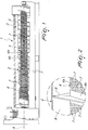
- the unit 1 therefore comprises a chamber 2 for containing at least one screw feeder 3; in turn, the screw feeder 3 comprises a roller 4, which rotates about its own longitudinal axis A, and a helical element 5, which is wound in a spiral around the roller 4.
- the chamber 2 is affected by an intake port for introducing the material to be pressed and by a discharge port for the pressed material, so as to define a forced pressing path 6 comprised between the chamber 2 and the screw feeder 3.
- the ports are not shown in the accompanying figures but can be simple nozzles or openings, provided along the chamber 2 and preferably (but not exclusively) facing end regions of the roller 4, so as to define a path 6 that is extended substantially along the entirety of such roller 4, maximizing the material pressing and expressing capabilities.
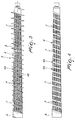
- the lateral surface of the roller 4 which is at least partially hollow, comprises a first portion 4a that has a helical extension around the axis A and has a plurality of holes 7 in order to allow the evacuation of the liquids progressively removed from the material during its advancement along the path 6. Furthermore, the lateral surface of the roller 4 comprises a second portion 4b, which also has a helical extension around the axis A and is complementary to the first portion 4a. The second portion 4b instead has a continuous non-perforated shape and indeed the helical element 5 is wound around the roller 4 at this second portion.
- the lateral surface of the roller 4 (the one that in practice delimits the path 6, together with the chamber 2 and the helical element 5) comprises two portions 4a, 4b, which are extended with a helical shape in a mutually parallel manner and define together the entire lateral surface (or at least a main segment thereof).
- the helical element 5 is welded to the roller 4 at the second portion 4b, and indeed the choice to keep the second portion 4b of the lateral surface of the roller 4 continuous and without holes 7 ensures optimum welding, avoiding or at least reducing the risk of cracks and failures, during the normal operation of the unit 1 and/or in case of abnormal stresses, possibly of excessive intensity.
- both the roller 4 and the chamber 2 are made of metal plate.
- At least the side walls of the chamber 2, interposed between the ports have a plurality of orifices, so as to ensure the evacuation of the liquids progressively removed from the material during its advancement along the path 6 through said orifices as well.
- the water can abandon the path 6 both through the holes 7 in the first portion 4a and through the orifices along the chamber 2.
- the roller 4 has a substantially cylindrical shape, while the helical element 5 has a pitch that at least partially decreases (on at least one segment of the roller 5) if measured along the path 6 from the intake port to the discharge port.
- This choice allows to obtain the progressive reduction of the volume available to the material during its advancement along the forced path 6 in order to obtain, as already anticipated, the pressing of such material.
- the protective scope claimed herein includes a second constructive solution, in which the roller 4 has a substantially conical shape, with a progressively increasing transverse cross-section, if measured along the path 6 from the intake port to the discharge port.
- the helical element 5 therefore has an at least partially constant pitch (on at least one segment of the roller 5) or even a slightly decreasing pitch, if measured along the path 6 from the intake port to the discharge port, achieving again the progressive reduction of the volume available to the material during its advancement along the forced path 6.
- chambers 2 having a conical or cylindrical shape, in any case shaped substantially complementarily to the shape and transverse space occupation of the helical element 5, so as to delimit fully the path 6, are conveniently adopted.
- the chamber 2 accommodates two screw feeders 3, each of which comprises a respective roller 4 and a corresponding helical element 5.
- the rollers 4 are substantially side by side and delimit, with the helical elements 5 and the chamber 2, a single forced path 6.
- the two screw feeders 3 can be arranged so that the turns of the helical element 5 of one screw feeder 3 enter, during rotation, the space comprised between two consecutive turns of the helical element 5 of the other screw feeder 3, and viceversa.
- the axis A of the roller 4 (of each roller 4) has an orientation selectively among a horizontal orientation, a vertical orientation and an inclined orientation (i.e., forming an angle comprised between 0° and 90° with the horizontal plane on which the entire unit 1 rests).
- the roller 4 is constituted substantially by a shaft, which rotates about the axis A and is internally hollow, so as to define an internal duct, which is indeed connected to the path 6 through the holes 7, for the evacuation of the liquids removed from the material.
- the liquid expressed from the material that passes through the holes 7 flows outside the unit 1 through the duct (arranged along the axis A) that is defined inside the shaft.
- the roller 4 is instead constituted substantially by a sleeve for the coaxial covering of a shaft, which rotates about the axis A.
- an interspace is defined between the sleeve and the shaft and is connected to the path 6 through the holes 7 in order to evacuate the liquids removed from the material (i.e., performing the role that in the other practical option is assigned to the internal duct of the shaft).
- the dimensional and geometric parameters of the helical shape of the portions 4a, 4b of the lateral surface of the roller 4 correspond to the material that is intended to pass through the forced path 6 and/or to the desired residual liquid content present in the material at the discharge port.
- the material to be pressed can be introduced in the chamber 2 through the intake port, which leads directly to the forced path 6, which is delimited by the screw feeder 3 and by the chamber 2 proper.
- the water (or other liquid) that is removed progressively can then abandon the chamber 2 through the holes 7 provided along the first portion 4a of the lateral surface of the roller 4 and preferably also through the orifices defined along the side walls of the chamber 2.
- the large filtering area available to the water ensures extremely high draining efficiencies and therefore better performance, which is assuredly of interest for users.
- the choice to weld or otherwise fix the helical element 5 to the roller 4 at the second portion 4b, which is not perforated, of its lateral surface ensures high mechanical strength, overcoming the problems of the background art, in which the helical elements welded to the perforated metal plates are subject to cracks (indeed at the weld) in case of abnormal mechanical stresses or frictions on the helical elements, with consequent failure of the shaft.
- Partial perforation (only on the second portion 4b) therefore allows the unit 1 to achieve a high increase in reliability without reducing the draining effect, since the area offered for draining (composed by the first portion 4a and preferably also by the side walls of the chamber 2) is in any case maximum.
- the higher mechanical reliability of the roller 4 further allows to utilize its potential more: for example, it is possible to reduce the rotation rate and increase the final content of dry substance in the pressed material, at the same time reducing machine downtimes, as well as maintenance interventions and inspections.
- the pressing unit according to the invention achieves fully the intended aim, since by adopting a roller that has a first portion with a helical shape provided with a plurality of holes and a second helical portion that is complementary to the first portion and is not perforated and around which the helical element is wound it is possible to achieve a high effectiveness in water removal without renouncing high mechanical strength.
- the materials used, as well as the dimensions, may be any according to requirements and to the state of the art.
Landscapes
- Engineering & Computer Science (AREA)
- Mechanical Engineering (AREA)
- Filtration Of Liquid (AREA)
Priority Applications (2)
| Application Number | Priority Date | Filing Date | Title |
|---|---|---|---|
| EP16425028.4A EP3228444B1 (fr) | 2016-04-04 | 2016-04-04 | Unité de compression servant à éliminer des liquides |
| ES16425028T ES2905309T3 (es) | 2016-04-04 | 2016-04-04 | Unidad de prensado para eliminar líquidos |
Applications Claiming Priority (1)
| Application Number | Priority Date | Filing Date | Title |
|---|---|---|---|
| EP16425028.4A EP3228444B1 (fr) | 2016-04-04 | 2016-04-04 | Unité de compression servant à éliminer des liquides |
Publications (2)
| Publication Number | Publication Date |
|---|---|
| EP3228444A1 true EP3228444A1 (fr) | 2017-10-11 |
| EP3228444B1 EP3228444B1 (fr) | 2021-12-22 |
Family
ID=56092861
Family Applications (1)
| Application Number | Title | Priority Date | Filing Date |
|---|---|---|---|
| EP16425028.4A Active EP3228444B1 (fr) | 2016-04-04 | 2016-04-04 | Unité de compression servant à éliminer des liquides |
Country Status (2)
| Country | Link |
|---|---|
| EP (1) | EP3228444B1 (fr) |
| ES (1) | ES2905309T3 (fr) |
Cited By (1)
| Publication number | Priority date | Publication date | Assignee | Title |
|---|---|---|---|---|
| EP4046788A1 (fr) * | 2021-02-19 | 2022-08-24 | Babbini S.P.A. | Presse |
Citations (5)
| Publication number | Priority date | Publication date | Assignee | Title |
|---|---|---|---|---|
| GB191126750A (en) * | 1911-11-29 | 1912-03-14 | Robert Hanson | Apparatus for Drying or Expressing Liquid from Tan Waste and other Plastic Materials. |
| EP0930152A1 (fr) * | 1998-01-15 | 1999-07-21 | Lionello Babbini | Presse à vis pour la déshydratation de produits humides |
| WO2003031166A1 (fr) * | 2001-10-10 | 2003-04-17 | Stord International Ass | Pressoir a vis, pressage de substance chargee de liquide, et mode d'utilisation |
| US20040035804A1 (en) * | 2000-08-04 | 2004-02-26 | Rudolf Bischof | Separating device for separating fluids from solids and use thereof |
| WO2004080704A1 (fr) * | 2003-03-14 | 2004-09-23 | Atlas-Stord Denmark A/S | Presse a vis comprenant une partie cylindrique |
-
2016
- 2016-04-04 EP EP16425028.4A patent/EP3228444B1/fr active Active
- 2016-04-04 ES ES16425028T patent/ES2905309T3/es active Active
Patent Citations (5)
| Publication number | Priority date | Publication date | Assignee | Title |
|---|---|---|---|---|
| GB191126750A (en) * | 1911-11-29 | 1912-03-14 | Robert Hanson | Apparatus for Drying or Expressing Liquid from Tan Waste and other Plastic Materials. |
| EP0930152A1 (fr) * | 1998-01-15 | 1999-07-21 | Lionello Babbini | Presse à vis pour la déshydratation de produits humides |
| US20040035804A1 (en) * | 2000-08-04 | 2004-02-26 | Rudolf Bischof | Separating device for separating fluids from solids and use thereof |
| WO2003031166A1 (fr) * | 2001-10-10 | 2003-04-17 | Stord International Ass | Pressoir a vis, pressage de substance chargee de liquide, et mode d'utilisation |
| WO2004080704A1 (fr) * | 2003-03-14 | 2004-09-23 | Atlas-Stord Denmark A/S | Presse a vis comprenant une partie cylindrique |
Cited By (1)
| Publication number | Priority date | Publication date | Assignee | Title |
|---|---|---|---|---|
| EP4046788A1 (fr) * | 2021-02-19 | 2022-08-24 | Babbini S.P.A. | Presse |
Also Published As
| Publication number | Publication date |
|---|---|
| ES2905309T3 (es) | 2022-04-07 |
| EP3228444B1 (fr) | 2021-12-22 |
Similar Documents
| Publication | Publication Date | Title |
|---|---|---|
| KR102267921B1 (ko) | 케이크의 강제 배출 구조를 갖는 슬러지 탈수장치 | |
| JP2010099643A (ja) | 圧縮脱液装置 | |
| WO2001026776A1 (fr) | Machine filtrante rotative a compression | |
| US7461591B2 (en) | Screw press for squeezing out fibrous material | |
| US10118358B2 (en) | Screw press for separation of liquid from bulk materials | |
| EP3228444B1 (fr) | Unité de compression servant à éliminer des liquides | |
| KR101468602B1 (ko) | 압착스크류와 타공망의 간극 조절이 용이한 스크류 탈수 장치 | |
| EP0930152A1 (fr) | Presse à vis pour la déshydratation de produits humides | |
| JP4152179B2 (ja) | スクリュープレスおよび脱水方法 | |
| JP4465384B2 (ja) | スクリュプレスの前処理装置 | |
| JP2019209277A (ja) | 加圧式回転板型固液分離装置 | |
| KR100940388B1 (ko) | 스크류탈수기 및 이를 포함하는 유기성폐기물 건조장치 | |
| EP1990181A2 (fr) | Presse pour déshydratation mécanique | |
| EP4046788B1 (fr) | Presse | |
| JP6183622B2 (ja) | ドラム型濃縮機の固形物回収システム | |
| JP2005501723A (ja) | 湿潤物質、特に、未処理の廃棄物の除湿のためのプレス機械 | |
| JP6301541B1 (ja) | 固液分離装置 | |
| US1769658A (en) | Press for the treatment of moist materials | |
| KR102461500B1 (ko) | 초고압을 이용한 압착식 탈수장치 | |
| WO2018160056A2 (fr) | Système d'extraction continue de liquide péricarpe et procédé associé | |
| EP1990180A2 (fr) | Presse pour déshydratation mécanique | |
| JP4518501B2 (ja) | ろ過装置 | |
| JP4493030B2 (ja) | ろ過装置 | |
| CN208883690U (zh) | 一种对螺污泥脱水机 | |
| JPH03291196A (ja) | スクリュープレス |
Legal Events
| Date | Code | Title | Description |
|---|---|---|---|
| PUAI | Public reference made under article 153(3) epc to a published international application that has entered the european phase |
Free format text: ORIGINAL CODE: 0009012 |
|
| STAA | Information on the status of an ep patent application or granted ep patent |
Free format text: STATUS: THE APPLICATION HAS BEEN PUBLISHED |
|
| AK | Designated contracting states |
Kind code of ref document: A1 Designated state(s): AL AT BE BG CH CY CZ DE DK EE ES FI FR GB GR HR HU IE IS IT LI LT LU LV MC MK MT NL NO PL PT RO RS SE SI SK SM TR |
|
| AX | Request for extension of the european patent |
Extension state: BA ME |
|
| STAA | Information on the status of an ep patent application or granted ep patent |
Free format text: STATUS: REQUEST FOR EXAMINATION WAS MADE |
|
| 17P | Request for examination filed |
Effective date: 20180403 |
|
| RBV | Designated contracting states (corrected) |
Designated state(s): AL AT BE BG CH CY CZ DE DK EE ES FI FR GB GR HR HU IE IS IT LI LT LU LV MC MK MT NL NO PL PT RO RS SE SI SK SM TR |
|
| GRAP | Despatch of communication of intention to grant a patent |
Free format text: ORIGINAL CODE: EPIDOSNIGR1 |
|
| STAA | Information on the status of an ep patent application or granted ep patent |
Free format text: STATUS: GRANT OF PATENT IS INTENDED |
|
| INTG | Intention to grant announced |
Effective date: 20210617 |
|
| GRAS | Grant fee paid |
Free format text: ORIGINAL CODE: EPIDOSNIGR3 |
|
| GRAA | (expected) grant |
Free format text: ORIGINAL CODE: 0009210 |
|
| STAA | Information on the status of an ep patent application or granted ep patent |
Free format text: STATUS: THE PATENT HAS BEEN GRANTED |
|
| AK | Designated contracting states |
Kind code of ref document: B1 Designated state(s): AL AT BE BG CH CY CZ DE DK EE ES FI FR GB GR HR HU IE IS IT LI LT LU LV MC MK MT NL NO PL PT RO RS SE SI SK SM TR |
|
| REG | Reference to a national code |
Ref country code: GB Ref legal event code: FG4D |
|
| REG | Reference to a national code |
Ref country code: CH Ref legal event code: EP |
|
| REG | Reference to a national code |
Ref country code: DE Ref legal event code: R096 Ref document number: 602016067578 Country of ref document: DE |
|
| REG | Reference to a national code |
Ref country code: AT Ref legal event code: REF Ref document number: 1456822 Country of ref document: AT Kind code of ref document: T Effective date: 20220115 |
|
| REG | Reference to a national code |
Ref country code: IE Ref legal event code: FG4D |
|
| REG | Reference to a national code |
Ref country code: ES Ref legal event code: FG2A Ref document number: 2905309 Country of ref document: ES Kind code of ref document: T3 Effective date: 20220407 |
|
| REG | Reference to a national code |
Ref country code: LT Ref legal event code: MG9D |
|
| PG25 | Lapsed in a contracting state [announced via postgrant information from national office to epo] |
Ref country code: RS Free format text: LAPSE BECAUSE OF FAILURE TO SUBMIT A TRANSLATION OF THE DESCRIPTION OR TO PAY THE FEE WITHIN THE PRESCRIBED TIME-LIMIT Effective date: 20211222 Ref country code: LT Free format text: LAPSE BECAUSE OF FAILURE TO SUBMIT A TRANSLATION OF THE DESCRIPTION OR TO PAY THE FEE WITHIN THE PRESCRIBED TIME-LIMIT Effective date: 20211222 Ref country code: FI Free format text: LAPSE BECAUSE OF FAILURE TO SUBMIT A TRANSLATION OF THE DESCRIPTION OR TO PAY THE FEE WITHIN THE PRESCRIBED TIME-LIMIT Effective date: 20211222 Ref country code: BG Free format text: LAPSE BECAUSE OF FAILURE TO SUBMIT A TRANSLATION OF THE DESCRIPTION OR TO PAY THE FEE WITHIN THE PRESCRIBED TIME-LIMIT Effective date: 20220322 |
|
| REG | Reference to a national code |
Ref country code: NL Ref legal event code: MP Effective date: 20211222 |
|
| REG | Reference to a national code |
Ref country code: AT Ref legal event code: MK05 Ref document number: 1456822 Country of ref document: AT Kind code of ref document: T Effective date: 20211222 |
|
| REG | Reference to a national code |
Ref country code: NO Ref legal event code: T2 Effective date: 20211222 |
|
| PG25 | Lapsed in a contracting state [announced via postgrant information from national office to epo] |
Ref country code: SE Free format text: LAPSE BECAUSE OF FAILURE TO SUBMIT A TRANSLATION OF THE DESCRIPTION OR TO PAY THE FEE WITHIN THE PRESCRIBED TIME-LIMIT Effective date: 20211222 Ref country code: LV Free format text: LAPSE BECAUSE OF FAILURE TO SUBMIT A TRANSLATION OF THE DESCRIPTION OR TO PAY THE FEE WITHIN THE PRESCRIBED TIME-LIMIT Effective date: 20211222 Ref country code: HR Free format text: LAPSE BECAUSE OF FAILURE TO SUBMIT A TRANSLATION OF THE DESCRIPTION OR TO PAY THE FEE WITHIN THE PRESCRIBED TIME-LIMIT Effective date: 20211222 Ref country code: GR Free format text: LAPSE BECAUSE OF FAILURE TO SUBMIT A TRANSLATION OF THE DESCRIPTION OR TO PAY THE FEE WITHIN THE PRESCRIBED TIME-LIMIT Effective date: 20220323 |
|
| PG25 | Lapsed in a contracting state [announced via postgrant information from national office to epo] |
Ref country code: NL Free format text: LAPSE BECAUSE OF FAILURE TO SUBMIT A TRANSLATION OF THE DESCRIPTION OR TO PAY THE FEE WITHIN THE PRESCRIBED TIME-LIMIT Effective date: 20211222 |
|
| PG25 | Lapsed in a contracting state [announced via postgrant information from national office to epo] |
Ref country code: SM Free format text: LAPSE BECAUSE OF FAILURE TO SUBMIT A TRANSLATION OF THE DESCRIPTION OR TO PAY THE FEE WITHIN THE PRESCRIBED TIME-LIMIT Effective date: 20211222 Ref country code: SK Free format text: LAPSE BECAUSE OF FAILURE TO SUBMIT A TRANSLATION OF THE DESCRIPTION OR TO PAY THE FEE WITHIN THE PRESCRIBED TIME-LIMIT Effective date: 20211222 Ref country code: RO Free format text: LAPSE BECAUSE OF FAILURE TO SUBMIT A TRANSLATION OF THE DESCRIPTION OR TO PAY THE FEE WITHIN THE PRESCRIBED TIME-LIMIT Effective date: 20211222 Ref country code: PT Free format text: LAPSE BECAUSE OF FAILURE TO SUBMIT A TRANSLATION OF THE DESCRIPTION OR TO PAY THE FEE WITHIN THE PRESCRIBED TIME-LIMIT Effective date: 20220422 Ref country code: EE Free format text: LAPSE BECAUSE OF FAILURE TO SUBMIT A TRANSLATION OF THE DESCRIPTION OR TO PAY THE FEE WITHIN THE PRESCRIBED TIME-LIMIT Effective date: 20211222 Ref country code: CZ Free format text: LAPSE BECAUSE OF FAILURE TO SUBMIT A TRANSLATION OF THE DESCRIPTION OR TO PAY THE FEE WITHIN THE PRESCRIBED TIME-LIMIT Effective date: 20211222 |
|
| PGFP | Annual fee paid to national office [announced via postgrant information from national office to epo] |
Ref country code: GB Payment date: 20220531 Year of fee payment: 7 |
|
| PG25 | Lapsed in a contracting state [announced via postgrant information from national office to epo] |
Ref country code: PL Free format text: LAPSE BECAUSE OF FAILURE TO SUBMIT A TRANSLATION OF THE DESCRIPTION OR TO PAY THE FEE WITHIN THE PRESCRIBED TIME-LIMIT Effective date: 20211222 Ref country code: AT Free format text: LAPSE BECAUSE OF FAILURE TO SUBMIT A TRANSLATION OF THE DESCRIPTION OR TO PAY THE FEE WITHIN THE PRESCRIBED TIME-LIMIT Effective date: 20211222 |
|
| REG | Reference to a national code |
Ref country code: DE Ref legal event code: R097 Ref document number: 602016067578 Country of ref document: DE |
|
| PG25 | Lapsed in a contracting state [announced via postgrant information from national office to epo] |
Ref country code: IS Free format text: LAPSE BECAUSE OF FAILURE TO SUBMIT A TRANSLATION OF THE DESCRIPTION OR TO PAY THE FEE WITHIN THE PRESCRIBED TIME-LIMIT Effective date: 20220422 |
|
| PLBE | No opposition filed within time limit |
Free format text: ORIGINAL CODE: 0009261 |
|
| STAA | Information on the status of an ep patent application or granted ep patent |
Free format text: STATUS: NO OPPOSITION FILED WITHIN TIME LIMIT |
|
| PG25 | Lapsed in a contracting state [announced via postgrant information from national office to epo] |
Ref country code: DK Free format text: LAPSE BECAUSE OF FAILURE TO SUBMIT A TRANSLATION OF THE DESCRIPTION OR TO PAY THE FEE WITHIN THE PRESCRIBED TIME-LIMIT Effective date: 20211222 Ref country code: AL Free format text: LAPSE BECAUSE OF FAILURE TO SUBMIT A TRANSLATION OF THE DESCRIPTION OR TO PAY THE FEE WITHIN THE PRESCRIBED TIME-LIMIT Effective date: 20211222 |
|
| 26N | No opposition filed |
Effective date: 20220923 |
|
| REG | Reference to a national code |
Ref country code: CH Ref legal event code: PL |
|
| REG | Reference to a national code |
Ref country code: BE Ref legal event code: MM Effective date: 20220430 |
|
| PG25 | Lapsed in a contracting state [announced via postgrant information from national office to epo] |
Ref country code: MC Free format text: LAPSE BECAUSE OF FAILURE TO SUBMIT A TRANSLATION OF THE DESCRIPTION OR TO PAY THE FEE WITHIN THE PRESCRIBED TIME-LIMIT Effective date: 20211222 Ref country code: LU Free format text: LAPSE BECAUSE OF NON-PAYMENT OF DUE FEES Effective date: 20220404 Ref country code: LI Free format text: LAPSE BECAUSE OF NON-PAYMENT OF DUE FEES Effective date: 20220430 Ref country code: CH Free format text: LAPSE BECAUSE OF NON-PAYMENT OF DUE FEES Effective date: 20220430 |
|
| PG25 | Lapsed in a contracting state [announced via postgrant information from national office to epo] |
Ref country code: SI Free format text: LAPSE BECAUSE OF FAILURE TO SUBMIT A TRANSLATION OF THE DESCRIPTION OR TO PAY THE FEE WITHIN THE PRESCRIBED TIME-LIMIT Effective date: 20211222 Ref country code: BE Free format text: LAPSE BECAUSE OF NON-PAYMENT OF DUE FEES Effective date: 20220430 |
|
| REG | Reference to a national code |
Ref country code: FR Ref legal event code: PLFP Year of fee payment: 8 |
|
| PG25 | Lapsed in a contracting state [announced via postgrant information from national office to epo] |
Ref country code: IE Free format text: LAPSE BECAUSE OF NON-PAYMENT OF DUE FEES Effective date: 20220404 |
|
| GBPC | Gb: european patent ceased through non-payment of renewal fee |
Effective date: 20230404 |
|
| PG25 | Lapsed in a contracting state [announced via postgrant information from national office to epo] |
Ref country code: GB Free format text: LAPSE BECAUSE OF NON-PAYMENT OF DUE FEES Effective date: 20230404 |
|
| PG25 | Lapsed in a contracting state [announced via postgrant information from national office to epo] |
Ref country code: GB Free format text: LAPSE BECAUSE OF NON-PAYMENT OF DUE FEES Effective date: 20230404 |
|
| PG25 | Lapsed in a contracting state [announced via postgrant information from national office to epo] |
Ref country code: HU Free format text: LAPSE BECAUSE OF FAILURE TO SUBMIT A TRANSLATION OF THE DESCRIPTION OR TO PAY THE FEE WITHIN THE PRESCRIBED TIME-LIMIT; INVALID AB INITIO Effective date: 20160404 |
|
| PG25 | Lapsed in a contracting state [announced via postgrant information from national office to epo] |
Ref country code: MK Free format text: LAPSE BECAUSE OF FAILURE TO SUBMIT A TRANSLATION OF THE DESCRIPTION OR TO PAY THE FEE WITHIN THE PRESCRIBED TIME-LIMIT Effective date: 20211222 Ref country code: CY Free format text: LAPSE BECAUSE OF FAILURE TO SUBMIT A TRANSLATION OF THE DESCRIPTION OR TO PAY THE FEE WITHIN THE PRESCRIBED TIME-LIMIT Effective date: 20211222 |
|
| PG25 | Lapsed in a contracting state [announced via postgrant information from national office to epo] |
Ref country code: MT Free format text: LAPSE BECAUSE OF FAILURE TO SUBMIT A TRANSLATION OF THE DESCRIPTION OR TO PAY THE FEE WITHIN THE PRESCRIBED TIME-LIMIT Effective date: 20211222 |
|
| PGFP | Annual fee paid to national office [announced via postgrant information from national office to epo] |
Ref country code: DE Payment date: 20250411 Year of fee payment: 10 |
|
| PGFP | Annual fee paid to national office [announced via postgrant information from national office to epo] |
Ref country code: ES Payment date: 20250516 Year of fee payment: 10 |
|
| PGFP | Annual fee paid to national office [announced via postgrant information from national office to epo] |
Ref country code: NO Payment date: 20250414 Year of fee payment: 10 |
|
| PGFP | Annual fee paid to national office [announced via postgrant information from national office to epo] |
Ref country code: FR Payment date: 20250410 Year of fee payment: 10 |
|
| PG25 | Lapsed in a contracting state [announced via postgrant information from national office to epo] |
Ref country code: TR Free format text: LAPSE BECAUSE OF FAILURE TO SUBMIT A TRANSLATION OF THE DESCRIPTION OR TO PAY THE FEE WITHIN THE PRESCRIBED TIME-LIMIT Effective date: 20211222 |
|
| PGFP | Annual fee paid to national office [announced via postgrant information from national office to epo] |
Ref country code: IT Payment date: 20260220 Year of fee payment: 11 |