EP3228483B1 - Luftreifen und verfahren zur herstellung davon - Google Patents
Luftreifen und verfahren zur herstellung davon Download PDFInfo
- Publication number
- EP3228483B1 EP3228483B1 EP15864967.3A EP15864967A EP3228483B1 EP 3228483 B1 EP3228483 B1 EP 3228483B1 EP 15864967 A EP15864967 A EP 15864967A EP 3228483 B1 EP3228483 B1 EP 3228483B1
- Authority
- EP
- European Patent Office
- Prior art keywords
- surface fastener
- tire
- cut portion
- fastener
- circumferential direction
- Prior art date
- Legal status (The legal status is an assumption and is not a legal conclusion. Google has not performed a legal analysis and makes no representation as to the accuracy of the status listed.)
- Active
Links
Images






Classifications
-
- B—PERFORMING OPERATIONS; TRANSPORTING
- B29—WORKING OF PLASTICS; WORKING OF SUBSTANCES IN A PLASTIC STATE IN GENERAL
- B29D—PRODUCING PARTICULAR ARTICLES FROM PLASTICS OR FROM SUBSTANCES IN A PLASTIC STATE
- B29D30/00—Producing pneumatic or solid tyres or parts thereof
- B29D30/06—Pneumatic tyres or parts thereof (e.g. produced by casting, moulding, compression moulding, injection moulding, centrifugal casting)
- B29D30/0681—Parts of pneumatic tyres; accessories, auxiliary operations
-
- B—PERFORMING OPERATIONS; TRANSPORTING
- B29—WORKING OF PLASTICS; WORKING OF SUBSTANCES IN A PLASTIC STATE IN GENERAL
- B29D—PRODUCING PARTICULAR ARTICLES FROM PLASTICS OR FROM SUBSTANCES IN A PLASTIC STATE
- B29D30/00—Producing pneumatic or solid tyres or parts thereof
- B29D30/0061—Accessories, details or auxiliary operations not otherwise provided for
-
- B—PERFORMING OPERATIONS; TRANSPORTING
- B29—WORKING OF PLASTICS; WORKING OF SUBSTANCES IN A PLASTIC STATE IN GENERAL
- B29D—PRODUCING PARTICULAR ARTICLES FROM PLASTICS OR FROM SUBSTANCES IN A PLASTIC STATE
- B29D30/00—Producing pneumatic or solid tyres or parts thereof
- B29D30/06—Pneumatic tyres or parts thereof (e.g. produced by casting, moulding, compression moulding, injection moulding, centrifugal casting)
-
- B—PERFORMING OPERATIONS; TRANSPORTING
- B60—VEHICLES IN GENERAL
- B60C—VEHICLE TYRES; TYRE INFLATION; TYRE CHANGING; CONNECTING VALVES TO INFLATABLE ELASTIC BODIES IN GENERAL; DEVICES OR ARRANGEMENTS RELATED TO TYRES
- B60C19/00—Tyre parts or constructions not otherwise provided for
-
- B—PERFORMING OPERATIONS; TRANSPORTING
- B60—VEHICLES IN GENERAL
- B60C—VEHICLE TYRES; TYRE INFLATION; TYRE CHANGING; CONNECTING VALVES TO INFLATABLE ELASTIC BODIES IN GENERAL; DEVICES OR ARRANGEMENTS RELATED TO TYRES
- B60C19/00—Tyre parts or constructions not otherwise provided for
- B60C19/002—Noise damping elements provided in the tyre structure or attached thereto, e.g. in the tyre interior
-
- B—PERFORMING OPERATIONS; TRANSPORTING
- B29—WORKING OF PLASTICS; WORKING OF SUBSTANCES IN A PLASTIC STATE IN GENERAL
- B29D—PRODUCING PARTICULAR ARTICLES FROM PLASTICS OR FROM SUBSTANCES IN A PLASTIC STATE
- B29D30/00—Producing pneumatic or solid tyres or parts thereof
- B29D30/0061—Accessories, details or auxiliary operations not otherwise provided for
- B29D2030/0072—Attaching fasteners to tyres, e.g. patches, in order to connect devices to tyres
-
- B—PERFORMING OPERATIONS; TRANSPORTING
- B60—VEHICLES IN GENERAL
- B60C—VEHICLE TYRES; TYRE INFLATION; TYRE CHANGING; CONNECTING VALVES TO INFLATABLE ELASTIC BODIES IN GENERAL; DEVICES OR ARRANGEMENTS RELATED TO TYRES
- B60C5/00—Inflatable pneumatic tyres or inner tubes
Definitions
- the present invention relates to a pneumatic tire provided with a fastener for attaching, as necessary, an affixture such as a noise absorbing member or the like to a tire inside surface, and a method for manufacturing the same. More particularly, the present invention relates to a pneumatic tire where a surface fastener can be mounted on a tire inner surface during a tire molding process and the surface fastener falling off during the tire molding process can be prevented effectively, and a method for manufacturing the same.
- pneumatic tires provided with surface fasteners on the tire inside surface in order to facilitate the attaching of affixtures such as noise absorbing members and the like have been proposed (e.g. see Patent Document 1).
- noise absorbing members are provided in a cavity portion in order to reduce resonance generated in the cavity portion; the abovementioned pneumatic tire with surface fastener allows for easy mounting and removal of accessories such as noise absorbing members as necessary.
- the surface fastener can be attached to an inner surface of a vulcanized pneumatic tire, but in this situation, there is a disadvantage where a production efficiency of the tire is extremely unfavorable. Therefore, it is proposed to mount the surface fastener on the tire inner surface during a tire molding process (for example, see Patent Document 2).
- a plurality of surface fasteners in a state of being separated from each other or a state of being separable from each other around a molding drum together with a rubber sheet, dispose these surface fasteners on an inner surface of a cylindrical carcass molded body, mold a green tire by inflating this carcass molded body into a toroidal shape and bonding this carcass molded body on an inner peripheral surface of a tread ring, and then vulcanize the green tire. While the surface fastener per se cannot stretch when the carcass molded body deforms into the toroidal shape, by having the plurality of surface fasteners dotting a tire circumferential direction, the surface fastener can be mounted on the tire inner surface during the tire molding process.
- An object of the present invention is to provide a pneumatic tire where a surface fastener can be mounted on a tire inner surface during a tire molding process and the surface fastener falling off during the tire molding process can be prevented effectively and a manufacturing method thereof.
- a band-shaped surface fastener extending in a tire circumferential direction is mounted on a tire inner surface, a cut portion composed of a group of a plurality of notches extending in a width direction of this surface fastener without traversing this surface fastener is formed in this surface fastener repetitively along the tire circumferential direction, the surface fastener is divided into a plurality of components by the notches, and the surface fastener is disposed on the tire inner surface in a state where the cut portion is stretched so the components are continuous in the tire circumferential direction.
- a manufacturing method of a pneumatic tire of the present invention for achieving the object above forms, in a band-shaped surface fastener, a cut portion repetitively along a longitudinal direction thereof composed of a group of a plurality of notches extending in a width direction of this surface fastener without traversing this surface fastener, divides the surface fastener into a plurality of components by the notches, disposes the surface fastener on an inner surface of a cylindrical carcass molded body so the longitudinal direction of the surface fastener extends in a tire circumferential direction, molds a green tire by inflating this carcass molded body into a toroidal shape and bonding this carcass molded body on an inner peripheral surface of a tread ring, places the surface fastener in a state where the cut portion is stretched so the components are continuous in the tire circumferential direction during this molding process of the green tire, and then vulcanizes the green tire.
- a surface fastener for achieving the object above is a band-shaped surface fastener mounted on a tire inner surface to extend in a tire circumferential direction that is provided with a cut portion repetitively along the tire circumferential direction composed of a group of a plurality of notches formed to extend in a width direction of this surface fastener without traversing this surface fastener, includes a plurality of components divided by the notches, and is used in a state where the cut portion is stretched so these components are continuous in the tire circumferential direction.
- the surface fastener is divided into the plurality of components by these notches, and the surface fastener is disposed on the tire inner surface in the state where the cut portion is stretched so the components are continuous in the tire circumferential direction, the surface fastener can be mounted on the tire inner surface during the tire molding process based on a manufacturing method such as described above. Therefore, the pneumatic tire provided with the surface fastener can be manufactured efficiently.
- the notch formed in the surface fastener extends in the width direction of the surface fastener without traversing the surface fastener and the surface fastener is disposed on the tire inner surface in the state where the plurality of components is continuous in the tire circumferential direction, even if a component of a portion were to be peeled off of the tire inner surface, this component would be held on the tire inner surface by the other components. Therefore, the surface fastener falling off during the tire molding process can be prevented effectively.
- a length of the notch in the state where the cut portion is stretched is preferably no less than 20% of a width of the surface fastener.
- the length of at least one notch included in each cut portion is preferably no less than 50% of the width of the surface fastener. In this situation, a distortion arising in each component when the surface fastener is stretched during the tire molding process can be suppressed and adhesion failure of the surface fastener can be prevented.
- At least one notch included in each cut portion to be communicated to one end portion in the width direction of the surface fastener and at least one other notch to be communicated to another end portion in the width direction of the surface fastener.
- a period in the tire circumferential direction of the cut portion in the state where this cut portion is stretched is preferably 15% to 150% of the width of the surface fastener.
- An area of a region surrounded by an outline of the surface fastener in the state where the cut portion is stretched is preferably 105% to 190% of an actual area of the surface fastener.
- a length in the tire circumferential direction of the surface fastener in the state where the cut portion is stretched is preferably 105% to 190% of a total length in the tire circumferential direction of the components of the surface fastener.
- a width of each component of the surface fastener is preferably 3% to 25% of the width of the surface fastener.
- the components of the surface fastener preferably include a plurality of first components configuring a main locking portion without deforming when the cut portion is stretched and a plurality of second components that deforms when the cut portion is stretched and links the first components to each other.
- the first component plays a role of the main locking portion and the second portion functions as a deforming portion at the time of stretching.
- a width of the first component is made greater than a width of the second component
- an engaging performance of the first component can be increased while decreasing the distortion arising in the second component.
- a configuration is preferable where the notches nearest to each other in a pair of adjacent cut portions are communicated to an end portion on the same side in the width direction of the surface fastener.
- an adhesive rubber layer between the surface fastener and the tire inner surface; for the surface fastener to be provided with a sheet-shaped substrate, a plurality of engaging elements formed on one surface of this substrate, and a plurality of anchor elements formed on another surface of this substrate; and to have the anchor element dig into the adhesive rubber layer.
- the adhesive rubber layer between the surface fastener and the carcass molded body it is preferable to dispose the adhesive rubber layer between the surface fastener and the carcass molded body; for the surface fastener to be provided with the sheet-shaped substrate, the plurality of engaging elements formed on the one surface of this substrate, and the plurality of anchor elements formed on the other surface of this substrate; and to have the anchor element dig into the adhesive rubber layer.
- the surface fastener can be fixed firmly on the tire inner surface.
- the adhesive rubber layer between the surface fastener and the tire inner surface it is preferable to dispose the adhesive rubber layer between the surface fastener and the tire inner surface, provide the cut portion in the surface fastener, and have the adhesive rubber layer extend continuously in the tire circumferential direction without being cut off at the cut portion.
- it is preferable to stack the surface fastener without the cut portion and the adhesive rubber layer form the cut portion by cutting only the surface fastener stacked with this adhesive rubber layer, and dispose this surface fastener formed with the cut portion on the inner surface of the carcass molded body together with the adhesive rubber layer.
- the manufacturing method of a pneumatic tire of the present invention it is preferable to engage the surface fastener without the cut portion and an element protection member with each other, form the cut portion by simultaneously cutting the surface fastener without the cut portion and the element protection member, mold the green tire by disposing this surface fastener formed with the cut portion on the inner surface of the carcass molded body together with the element protection member, and peel off the element protection member from the surface fastener after vulcanizing this green tire.
- the surface fastener can be protected by the element protection member during the vulcanization process and the element protection member comes to have a structure of being linked continuously similarly to the surface fastener, a peeling operation of the element protection member can be performed easily.
- FIGS. 1 and 2 illustrate a pneumatic tire formed according to an embodiment of the present invention
- FIGS. 3 to 5B illustrate a fastener used in the present invention.
- 1 is a tread portion; 2 is a side wall portion; and 3 is a bead portion.
- the carcass layer 4 is mounted between the left-right pair of bead portions 3, 3.
- the carcass layer 4 is wrapped back around a bead core 5 disposed in each of the bead portions 3 from the inside of the tire to the outside of the tire.
- an inner liner layer 6 is disposed in an area on a tire-cavity side of the carcass layer 4.
- a plurality of belt layers 8 is embedded to an outer circumferential side of the carcass layer 4 in the tread portion 1.
- a surface fastener 10 is disposed via an adhesive rubber layer 8 in a region corresponding to the tread portion 1 of a tire inner surface S.
- the surface fastener 10 is provided with a substrate 11 forming a sheet shape and a plurality of engaging elements 12 formed on one surface of this substrate 11.
- the engaging elements 12 form columns along a tire circumferential direction C and are disposed so a plurality of columns lines up along a tire width direction W.
- a shape of the engaging element 12 is not particularly limited, it is sufficient that, for example, a T shape or an arrow shape (including a double-arrow shape) where, as illustrated, a tip portion branches in two and extends in a surface direction of the surface fastener 10.
- the surface fastener 10 configured in this manner has the substrate 11 vulcanized and adhered on the tire inner surface S so the engaging element 12 is positioned on a tire-cavity side.
- an affixture such as a noise-absorbing member 20 is installed to the surface fastener 10 as necessary.
- a noise-absorbing member 20 composed of polyurethane foam
- the noise-absorbing member 20 can be engaged as is with the surface fastener 10 by utilizing a mesh structure of this polyurethane foam.
- another surface fastener that can engage with the surface fastener 10 may be installed to the affixture.
- the affixture 20 other than noise absorbing members include temperature sensors, transponders, and the like.
- a disposition location of the surface fastener 10 on the tire inner surface S can be selected freely according to the type of affixture.
- FIG. 3 illustrate other fasteners used in the present invention.
- the surface fastener 10 is provided with the substrate 11 forming the sheet shape, the plurality of engaging elements 12 formed on the one surface of this substrate 11, and a plurality of anchor elements 13 formed on another surface of this substrate 11.
- the anchor elements 13 form columns along the tire circumferential direction C and are disposed so a plurality of columns lines up along the tire width direction W.
- a shape of the anchor element 13 is not particularly limited, it is sufficient that, for example, a T shape where, as illustrated, a tip portion branches in two and extends in the surface direction of the surface fastener 10.
- FIG. 4 because these anchor elements 13 are embedded in the adhesive rubber layer 8 stacked with the inner liner layer 6, an adhesive force of the surface fastener 10 on the tire inner surface S can be improved.
- the surface fastener 10 described above can be molded from a thermoplastic resin such as nylon, polyester, polyethylene, polypropylene, polyvinyl chloride, polystyrene, acrylonitrile/styrene, acrylonitrile/butadiene/styrene, or polyethylene terephthalate.
- a resin whose main ingredient is a polyamide or a polyester is preferable.
- FIGS. 5A and 5B illustrate other fasteners used in the present invention.
- a cut portion 15 composed of a group of a plurality of notches 14 is formed in the band-shaped surface fastener 10 repetitively along a longitudinal direction of the surface fastener 10.
- Each notch 14 extends in a width direction of the surface fastener 10 without traversing the surface fastener 10.
- the plurality of notches 14 is disposed in each cut portion 15 extending continuously over an entirety of the width direction of the surface fastener 10.
- each cut portion 15 is communicated with one end portion in the width direction of the surface fastener 10 and at least one other notch 14 is communicated with another end portion in the width direction of the surface fastener 10.
- the surface fastener 10 is divided by the notches 14 into a plurality of components 16 forming a strip shape.
- the surface fastener 10 maintains an overall integrity.
- the surface fastener 10 having such a plurality of cut portions 15 is used so the longitudinal direction of the surface fastener 10 extends in the tire circumferential direction C and, as illustrated in FIG. 5B , is disposed on the tire inner surface S in a state where the cut portion 15 is stretched so the components 16 thereof are continuous in the tire circumferential direction C.
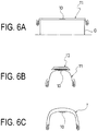
- FIGS. 6A to 6C illustrate a method for manufacturing the pneumatic tire of the present invention.
- the surface fastener 10 having the cut portion 15 described above is disposed on an inner surface of the cylindrical carcass molded body T1 so the longitudinal direction of the surface fastener 10 extends in the tire circumferential direction C.
- the surface fastener 10 is in a state where the cut portion 15 is closed.
- a single surface fastener 10 may be disposed on a tire circumference or a plurality of surface fasteners 10 may be disposed lined up on the tire circumference.
- the carcass molded body T1 is disposed on an inner peripheral side of an annular tread ring T2 and the carcass molded body T1 is inflated into a toroidal shape and bonded on the inner peripheral surface of the tread ring T2.
- a green tire T is molded that is provided with the surface fastener 10 on the tire inner surface S.
- the surface fastener 10 is in a state where the cut portion 15 is stretched so the components 16 are continuous in the tire circumferential direction C.
- the green tire T is vulcanized in a mold.
- the surface fastener 10 is divided into the plurality of components 16 by these notches 14, and the surface fastener 10 is disposed on the tire inner surface S in the state where the cut portion 15 is stretched so the components 16 are continuous in the tire circumferential direction C, the surface fastener 10 can be mounted on the tire inner surface S in the tire molding process based on a manufacturing method such as described above. Therefore, a pneumatic tire provided with the surface fastener 10 can be manufactured efficiently.
- the notch 14 formed in the surface fastener 10 extends in the width direction thereof without traversing the surface fastener 10 and the surface fastener 10 is disposed on the tire inner surface S in the state where the plurality of components 16 is continuous in the tire circumferential direction C, even if the component 16 of one portion were to be peeled off of the tire inner surface S, this component 16 would be held on the tire inner surface S by the other components 16. Therefore, the surface fastener 10 falling off during the tire molding process can be prevented effectively.
- a length L14 of the notch 14 in the state where the cut portion 15 is stretched is no less than 20%, preferably no less than 35%, and more preferably no less than 45% of a width W of the surface fastener 10; it is sufficient that an upper limit thereof is 98%.
- an upper limit thereof is 98%.
- a period P in the tire circumferential direction of the cut portion 15 in the state where this cut portion 15 is stretched is 15% to 150% of the width W of the surface fastener 10.
- an area of a region surrounded by an outline of the surface fastener 10 in the state where the cut portion 15 is stretched is 105% to 190% and preferably 120% to 170% of an actual area of the surface fastener 10.
- the area of the region surrounded by the outline of the surface fastener 10 is smaller than the lower limit, a material efficiency of the surface fastener 10 becomes unfavorable; conversely, when this is greater than the upper limit, out-of-plane deformation arises more easily in the component 16 of the surface fastener 10 and this out-of-plane deformation becomes a cause of adhesion failure.
- the area of the region surrounded by the outline of the surface fastener 10 in the state where the cut portion 15 is stretched is the product of the width W of the surface fastener 10 in the state where the cut portion 15 is stretched and the length L in the tire circumferential direction of the surface fastener 10 in the state where the cut portion 15 is stretched.
- the length L in the tire circumferential direction of the surface fastener 10 in the state where the cut portion 15 is stretched is 105% to 190% and preferably 120% to 170% of a total length Lt in the tire circumferential direction of the component 16 of the surface fastener 10.
- a width W16 of each component 16 of the surface fastener 10 is 3% to 25% and preferably 3.5% to 20% of the width W of the surface fastener 10.
- the width W16 of each component 16 is smaller than the lower limit, the engagement function of the surface fastener 10 may be impaired; conversely, when this is greater than the upper limit, out-of-plane deformation arises more easily in the component 16 of the surface fastener 10 and this out-of-plane deformation becomes a cause of adhesion failure.
- the component 16 of the surface fastener 10 preferably includes a plurality of first components 16A configuring a main locking portion without deforming when the cut portion 15 is stretched and a plurality of second components 16B that deforms when the cut portion 15 is stretched and links the first components to each other. More specifically, one end of the first component 16A is linked to the second component 16B adjacent thereto and another end is a free end. Meanwhile, both ends of the second component are linked to the first component 16A or the second component 16B adjacent thereto.
- first component 16A and the second component 16B a configuration is favorable where the notches 14, 14 nearest to each other in a pair of adjacent cut portions 15, 15 are communicated to an end portion on the same side in the width direction of the surface fastener 10. Particularly, it is sufficient to make the lengths L14 of the notches 14, 14 nearest to each other in the pair of adjacent cut portions 15, 15 the same.
- the first component 16A and the second component 16B are mixed in this manner, the first component 16A plays a role of the main locking portion and the second component 16B functions as a deforming portion at the time of stretching.
- an engaging performance of the first component 16A can be increased while decreasing the distortion arising in the second component 16B.
- the surface fastener 10 stretches in the tire circumferential direction, because an orientation of the engaging element 12 does not change at the first component 16A, an engagement force based on the engaging element 12 can be exhibited maximally.
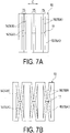
- FIGS. 7A and 7B illustrate other fasteners used in the present invention.
- the cut portion 15 composed of the group of the plurality of notches 14 extending in the width direction of the surface fastener 10 without traversing the surface fastener 10 is formed in the band-shaped surface fastener 10 repetitively along the longitudinal direction of the surface fastener 10.
- the notches 14 include a pair of notches 14A extending from both sides in the width direction of the surface fastener 10 and a pair of notches 14B that is disposed on both sides of this pair of notches 14A and has both ends closed.
- a notch 17 is formed that extends in the longitudinal direction of the surface fastener to link the pair of notches 14B, 14B.
- the component 16B divided by the notch 17 moves to a width-direction outer side of the surface fastener 10 as it deforms.
- FIGS. 8A and 8B illustrate a plan-view structure of still another surface fastener used in the present invention.
- the cut portion 15 composed of the group of the plurality of notches 14 extending in the width direction of the surface fastener 10 without traversing the surface fastener 10 is formed in the band-shaped surface fastener 10 repetitively along the longitudinal direction of the surface fastener 10.
- the notches 14 include the pair of notches 14A extending from both sides in the width direction of the surface fastener 10 and the pair of notches 14B that is disposed on one side of this pair of notches 14A and has both ends closed.
- a notch (slit) 18 is formed that extends in the longitudinal direction of the surface fastener 10 to link the pair of notches 14B, 14B.
- the component 16A divided by the notch 18 moves to a width-direction inner side of the surface fastener 10 as the component 16B deforms.
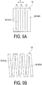
- FIGS. 9A and 9B illustrate a plan-view structure of still another surface fastener used in the present invention.
- the cut portion 15 composed of the group of the plurality of notches 14 extending in the width direction of the surface fastener 10 without traversing the surface fastener 10 is formed in the band-shaped surface fastener 10 repetitively along the longitudinal direction of the surface fastener 10.
- the notches 14 include only the pair of notches 14A extending from both sides in the width direction of the surface fastener 10.
- FIGS. 10A and 10B illustrate a plan-view structure of still another surface fastener used in the present invention.
- the cut portion 15 composed of the group of the plurality of notches 14 extending in the width direction of the surface fastener 10 without traversing the surface fastener 10 is formed in the band-shaped surface fastener 10 repetitively along the longitudinal direction of the surface fastener 10.
- the notches 14 include the pair of notches 14A extending from both sides in the width direction of the surface fastener 10, one notch 14B that is disposed between the pair of notches 14A and has both ends closed, and two notches 14B that are disposed on one side of the pair of notches 14A and has both ends closed.
- the adhesive rubber layer 8 is disposed between the surface fastener 10 and the tire inner surface S; the surface fastener 10 is provided with the sheet-shaped substrate 11, the plurality of engaging elements 12 formed on the one surface of this substrate 11, and the plurality of anchor elements 13 formed on the other surface of this substrate 11; and the anchor element 13 digs into the adhesive layer 8.
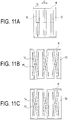
- FIGS. 11A to 11C illustrate a method for manufacturing the pneumatic tire of the present invention.
- the adhesive rubber layer 8 between the surface fastener 10 and the tire inner surface S, it is preferable to provide the cut portion 15 in the surface fastener 10 and have the adhesive rubber layer 8 extend continuously in the tire circumferential direction without being cut off at the cut portion 15.
- FIGS. 12A to 12C illustrate a method for manufacturing the pneumatic tire of the present invention.
- it is sufficient to engage the surface fastener 10 without the cut portion 15 and an element protection member 19 to each other; stack the surface fastener 10 and the adhesive rubber layer 8 as necessary; as illustrated in FIG. 12A , form the cut portion 15 by simultaneously cutting the surface fastener 10 without the cut portion 15 and the element protection member 19; and dispose the surface fastener 10 formed with the cut portion 15 on the inner surface of the carcass molded body T1 together with the element protection member 19.
- the element protection member 19 for example, another surface fastener forming a pair with the surface fastener 10 can be used.
- the element protection member 19 When the green tire T is molded using the carcass molded body T1 provided with such a surface fastener 10 and element protection member 19, as illustrated in FIG. 12B , when the surface fastener 10 stretches, the element protection member 19 also stretches in the tire circumferential direction. Moreover as illustrated in FIG. 12C , the element protection member 19 is peeled off from the surface fastener 10 upon vulcanizing the green tire T. In this situation, the surface fastener 10 can be protected by the element protection member 19 during the vulcanization process. That is, the engaging element 12 of the surface fastener 10 can be prevented from being crushed during the vulcanization process. Moreover, because the element protection member 19 comes to have a structure of being linked continuously similarly to the surface fastener 10, a peeling operation of the element protection member 19 can be performed easily.
- tires of Examples 1 to 5 where the structure of the surface fastener is made to differ are fabricated.
- the cut portion composed of the group of the plurality of notches extending in the width direction of this surface fastener without traversing this surface fastener is formed in the band-shaped surface fastener repetitively along the longitudinal direction of the surface fastener, the surface fastener is divided into the plurality of components by these notches, the surface fastener is disposed on the inner surface of the cylindrical carcass molded body so the longitudinal direction of the surface fastener extends in the tire circumferential direction, the green tire is molded by inflating this carcass molded body into the toroidal shape and bonding the carcass molded body on the inner peripheral surface of the tread ring, the surface fastener is placed in the state where the cut portion is stretched so the components of the surface fastener are continuous in the tire circumferential direction during this molding process of the green tire, and then the green tire is vulcanized.
- FIGS. 5A and 5B (Example 1), FIGS. 7A and 7B (Example 2), FIGS. 8A and 8B (Example 3), FIGS. 9A and 9B (Example 4), and FIGS. 10A and 10B (Example 5) are adopted.
- a tire of a conventional example is fabricated by the same method as Examples 1 to 5 other than disposing a large number of surface fasteners on the inner surface of the cylindrical carcass molded body at intervals along the tire circumferential direction.
- the surface fastener was able to be mounted on the tire inner surface during the tire molding process without having the surface fastener fall off. Meanwhile, in the conventional example, a portion of the surface fasteners was lifted from the tire inner surface in the course of inflating the carcass molded body to vulcanizing the green tire and this lifted surface fastener fell off from the tire inner surface.
Landscapes
- Engineering & Computer Science (AREA)
- Mechanical Engineering (AREA)
- Tires In General (AREA)
- Tyre Moulding (AREA)
Claims (12)
- Luftreifen, wobei
ein bandförmiges Oberflächenbefestigungsmittel (10), das sich in einer Reifenumfangsrichtung erstreckt, an einer Reifeninnenoberfläche (S) montiert ist;
ein geschnittener Abschnitt (15), der aus einer Gruppe einer Mehrzahl von Kerben (14) besteht, die sich in einer Breitenrichtung dieses Oberflächenbefestigungsmittels (10) erstrecken, ohne dieses Oberflächenbefestigungsmittel (10) zu durchqueren, in diesem Oberflächenbefestigungsmittel (10) wiederholt entlang der Reifenumfangsrichtung gebildet ist;
das Oberflächenbefestigungsmittel (10) durch die Kerben (14) in eine Mehrzahl von Bestandteilen (16) unterteilt ist; dadurch gekennzeichnet, dass
das Oberflächenbefestigungsmittel (10) auf der Reifeninnenoberfläche (S) in einem Zustand angeordnet ist, in dem der geschnittene Abschnitt (15) so gedehnt ist, dass die Bestandteile (16) in der Reifenumfangsrichtung kontinuierlich sind. - Luftreifen gemäß Anspruch 1, wobei
eine Länge der Kerbe (14) in dem Zustand, in dem der geschnittene Abschnitt (15) gedehnt ist, nicht weniger als 20 % einer Breite des Oberflächenbefestigungsmittels (10) beträgt. - Luftreifen gemäß Anspruch 1 oder 2, wobei
eine Periode des geschnittenen Abschnitts (15) in der Reifenumfangsrichtung in dem Zustand, in dem dieser geschnittene Abschnitt gedehnt ist, 15 % bis 150 % einer Breite des Oberflächenbefestigungsmittels (10) beträgt. - Luftreifen gemäß einem der Ansprüche 1 bis 3, wobei
eine Fläche eines Bereichs, der von einem Umriss des Oberflächenbefestigungsmittels (10) in dem Zustand umgeben ist, in dem der geschnittene Abschnitt (15) gedehnt ist, 105 % bis 190 % einer tatsächlichen Fläche des Oberflächenbefestigungsmittels (10) beträgt. - Luftreifen gemäß einem der Ansprüche 1 bis 4, wobei
eine Länge des Oberflächenbefestigungsmittels (10) in der Reifenumfangsrichtung in dem Zustand, in dem der geschnittene Abschnitt (15) gestreckt ist, 105 % bis 190 % einer Gesamtlänge der Bestandteile (16) des Oberflächenbefestigungsmittels (10) in der Reifenumfangsrichtung beträgt. - Luftreifen gemäß einem der Ansprüche 1 bis 5, wobei
eine Breite jedes Bestandteils (16) des Oberflächenbefestigungsmittels (10) 3 % bis 25 % der Breite des Oberflächenbefestigungsmittels (10) beträgt. - Luftreifen gemäß einem der Ansprüche 1 bis 6, wobei
die Bestandteile (16) des Oberflächenbefestigungsmittels (10) eine Mehrzahl von ersten Bestandteilen (16A), die einen Hauptverriegelungsabschnitt konfigurieren, ohne sich zu verformen, wenn der geschnittene Abschnitt (15) gedehnt wird, und eine Mehrzahl von zweiten Bestandteilen (16B) einschließen, die sich verformen, wenn der geschnittene Abschnitt (15) gedehnt wird, und die ersten Bestandteile (16A) miteinander verbinden. - Luftreifen gemäß Anspruch 7, wobei
eine Breite des ersten Bestandteils (16A) größer als eine Breite des zweiten Bestandteils (16B) ist. - Luftreifen gemäß einem der Ansprüche 1 bis 8, wobei
eine haftende Gummischicht (8) zwischen dem Oberflächenbefestigungsmittel (10) und der Reifeninnenoberfläche (S) angeordnet ist; das Oberflächenbefestigungsmittel (10) mit einem flächengebildeförmigen Substrat (11), einer Mehrzahl von Eingriffselementen (12), die auf einer Oberfläche dieses Substrats (11) gebildet sind, und einer Mehrzahl von Ankerelementen (13), die auf einer anderen Oberfläche dieses Substrats (11) gebildet sind, versehen ist; und das Ankerelement (13) hergestellt ist, um in die haftende Gummischicht (8) zu einzudringen. - Luftreifen gemäß einem der Ansprüche 1 bis 9, wobei
eine haftende Gummischicht (8) zwischen dem Oberflächenbefestigungsmittel (10) und der Reifeninnenoberfläche (S) angeordnet ist, der geschnittene Abschnitt (15) in dem Befestigungsmittel (10) bereitgestellt ist und die haftende Gummischicht (8) sich kontinuierlich in der Reifenumfangsrichtung erstreckt, ohne an dem geschnittenen Abschnitt (15) abgeschnitten zu sein. - Herstellungsverfahren eines Luftreifens, das die folgenden Schritte umfasst:Bilden, in einem bandförmigen Oberflächenbefestigungsmittel (10), eines sich entlang einer Längsrichtung davon wiederholenden geschnittenen Abschnitts (15), der aus einer Gruppe einer Mehrzahl von Kerben (14) besteht, die sich in einer Breitenrichtung dieses Oberflächenbefestigungsmittels (10) erstrecken, ohne dieses Oberflächenbefestigungsmittel (10) zu durchqueren;Teilen des Oberflächenbefestigungsmittels in eine Mehrzahl von Bestandteilen (16) durch die Kerben (14);Anordnen des Oberflächenbefestigungsmittels (10) auf einer Innenoberfläche eines zylindrischen Karkassenformkörpers, sodass die Längsrichtung des Oberflächenbefestigungsmittels (10) sich in einer Reifenumfangsrichtung erstreckt;Formen eines Reifenrohlings durch Aufpumpen dieses Karkassenformkörpers in eine Torusform und Binden dieses Karkassenformkörpers an eine Innenumfangsoberfläche eines Laufflächenrings;Anordnen des Oberflächenbefestigungsmittels (10) in einem Zustand, in dem der geschnittene Abschnitt (15) so gedehnt ist, dass die Bestandteile (16) während dieses Formungsprozesses des Reifenrohlings in der Reifenumfangsrichtung kontinuierlich sind; und anschließendVulkanisieren des Reifenrohlings.
- Herstellungsverfahren eines Luftreifens gemäß Anspruch 11, wobei
eine Länge der Kerbe (14) in dem Zustand, in dem der geschnittene Abschnitt (15) gedehnt ist, nicht weniger als 20 % einer Breite des Oberflächenbefestigungsmittels (10) beträgt.
Applications Claiming Priority (2)
| Application Number | Priority Date | Filing Date | Title |
|---|---|---|---|
| JP2014244233A JP6516456B2 (ja) | 2014-12-02 | 2014-12-02 | 空気入りタイヤ及びその製造方法 |
| PCT/JP2015/076265 WO2016088428A1 (ja) | 2014-12-02 | 2015-09-16 | 空気入りタイヤ及びその製造方法 |
Publications (4)
| Publication Number | Publication Date |
|---|---|
| EP3228483A1 EP3228483A1 (de) | 2017-10-11 |
| EP3228483A4 EP3228483A4 (de) | 2018-07-18 |
| EP3228483B1 true EP3228483B1 (de) | 2020-12-30 |
| EP3228483B9 EP3228483B9 (de) | 2021-05-12 |
Family
ID=56091386
Family Applications (1)
| Application Number | Title | Priority Date | Filing Date |
|---|---|---|---|
| EP15864967.3A Active EP3228483B9 (de) | 2014-12-02 | 2015-09-16 | Luftreifen und verfahren zur herstellung davon |
Country Status (5)
| Country | Link |
|---|---|
| US (1) | US11014318B2 (de) |
| EP (1) | EP3228483B9 (de) |
| JP (1) | JP6516456B2 (de) |
| CN (1) | CN107107685B (de) |
| WO (1) | WO2016088428A1 (de) |
Families Citing this family (7)
| Publication number | Priority date | Publication date | Assignee | Title |
|---|---|---|---|---|
| JP6435233B2 (ja) * | 2015-04-21 | 2018-12-05 | 横浜ゴム株式会社 | 空気入りタイヤ及びその製造方法 |
| USD852127S1 (en) | 2017-05-31 | 2019-06-25 | The Yokohama Rubber Co., Ltd. | Automobile tire with hook and loop fastener |
| USD852128S1 (en) | 2017-05-31 | 2019-06-25 | The Yokohama Rubber Co., Ltd. | Automobile tire with hook and loop fastener |
| JP7205237B2 (ja) * | 2019-01-09 | 2023-01-17 | 横浜ゴム株式会社 | 空気入りタイヤ |
| US12138969B2 (en) * | 2020-02-17 | 2024-11-12 | The Yokohama Rubber Co., Ltd. | Pneumatic tire |
| CN112140604A (zh) * | 2020-09-29 | 2020-12-29 | 山东玲珑橡胶科技有限公司 | 一种轮胎内附加电子元件的底座及其生产方法 |
| KR102474618B1 (ko) * | 2021-03-03 | 2022-12-06 | 넥센타이어 주식회사 | 공기입 타이어의 흡음재의 장착 구조 |
Family Cites Families (13)
| Publication number | Priority date | Publication date | Assignee | Title |
|---|---|---|---|---|
| JP3916625B2 (ja) | 2004-08-05 | 2007-05-16 | 横浜ゴム株式会社 | 空気入りタイヤ |
| FR2883222B1 (fr) | 2005-03-21 | 2007-05-18 | Michelin Soc Tech | Procede d'obtention d'un fil preforme destine a etre integre lors de la fabrication d'un pneummatique, ensemble d'une feuille de gomme et d'un fil preforme |
| JP4299813B2 (ja) * | 2005-07-20 | 2009-07-22 | 住友ゴム工業株式会社 | 空気入りタイヤ |
| JP4532520B2 (ja) * | 2007-04-25 | 2010-08-25 | 横浜ゴム株式会社 | 面ファスナー付き空気入りタイヤ及びその製造方法 |
| JP4850125B2 (ja) * | 2007-05-14 | 2012-01-11 | クラレプラスチックス株式会社 | 小片を等間隔に設置するための帯状体 |
| FR2919226B1 (fr) * | 2007-07-24 | 2009-10-09 | Michelin Soc Tech | Pneumatique equipe pour la fixation d'un objet a sa paroi et son procede de fabrication. |
| JP4989449B2 (ja) | 2007-12-25 | 2012-08-01 | 横浜ゴム株式会社 | 空気入りタイヤの製造方法及び空気入りタイヤ |
| JP5496797B2 (ja) * | 2010-07-05 | 2014-05-21 | 横浜ゴム株式会社 | 空気入りタイヤ |
| US20120330266A1 (en) | 2011-06-21 | 2012-12-27 | 3M Innovative Properties Company | Reticulated mechanical fastening patch and method of making the same |
| US9138031B2 (en) | 2011-02-16 | 2015-09-22 | 3M Innovative Properties Company | Method of making a mechanical fastening strip and reticulated mechanical fastening strip therefrom |
| TWI616195B (zh) * | 2011-02-16 | 2018-03-01 | 3M新設資產公司 | 製造一機械式緊固件之方法、網狀機械式緊固件、及網狀機械式緊固層壓物 |
| JP6002562B2 (ja) | 2012-12-05 | 2016-10-05 | 横浜ゴム株式会社 | 面ファスナー付き空気入りタイヤ及びその製造方法 |
| JP5750521B2 (ja) * | 2014-01-24 | 2015-07-22 | 横浜ゴム株式会社 | 空気入りタイヤ |
-
2014
- 2014-12-02 JP JP2014244233A patent/JP6516456B2/ja active Active
-
2015
- 2015-09-16 EP EP15864967.3A patent/EP3228483B9/de active Active
- 2015-09-16 US US15/532,960 patent/US11014318B2/en active Active
- 2015-09-16 CN CN201580061624.7A patent/CN107107685B/zh active Active
- 2015-09-16 WO PCT/JP2015/076265 patent/WO2016088428A1/ja not_active Ceased
Non-Patent Citations (1)
| Title |
|---|
| None * |
Also Published As
| Publication number | Publication date |
|---|---|
| CN107107685A (zh) | 2017-08-29 |
| EP3228483B9 (de) | 2021-05-12 |
| WO2016088428A1 (ja) | 2016-06-09 |
| EP3228483A1 (de) | 2017-10-11 |
| CN107107685B (zh) | 2019-10-11 |
| JP2016107671A (ja) | 2016-06-20 |
| US11014318B2 (en) | 2021-05-25 |
| JP6516456B2 (ja) | 2019-05-22 |
| US20190001600A1 (en) | 2019-01-03 |
| EP3228483A4 (de) | 2018-07-18 |
Similar Documents
| Publication | Publication Date | Title |
|---|---|---|
| EP3228483B1 (de) | Luftreifen und verfahren zur herstellung davon | |
| EP3225425B1 (de) | Reifen | |
| JP5496797B2 (ja) | 空気入りタイヤ | |
| JP4989449B2 (ja) | 空気入りタイヤの製造方法及び空気入りタイヤ | |
| JP6002562B2 (ja) | 面ファスナー付き空気入りタイヤ及びその製造方法 | |
| EP3225424B1 (de) | Reifen | |
| US20100043951A1 (en) | Pneumatic tire | |
| JP2008272954A (ja) | 面ファスナー付き空気入りタイヤ及びその製造方法 | |
| US10639935B2 (en) | Tire with tensioned spokes | |
| EP1559588A4 (de) | Radialreifen mit schraubenförmig gewickelter umfangsgürtellage | |
| US8647455B2 (en) | Process for manufacturing pneumatic tire | |
| JP5862072B2 (ja) | 空気入りタイヤの製造方法 | |
| CN106457932B (zh) | 充气轮胎及其制造方法 | |
| JP5994874B2 (ja) | 空気入りタイヤ及びその製造方法 | |
| JPH068014B2 (ja) | タイヤ用滑止具の製造方法 | |
| JP3305836B2 (ja) | 空気入りラジアルタイヤの製造方法 | |
| US20170232797A1 (en) | Pneumatic tire | |
| JP2015231710A (ja) | タイヤ内腔に面ファスナーを有する空気入りタイヤの製造方法 |
Legal Events
| Date | Code | Title | Description |
|---|---|---|---|
| STAA | Information on the status of an ep patent application or granted ep patent |
Free format text: STATUS: THE INTERNATIONAL PUBLICATION HAS BEEN MADE |
|
| PUAI | Public reference made under article 153(3) epc to a published international application that has entered the european phase |
Free format text: ORIGINAL CODE: 0009012 |
|
| STAA | Information on the status of an ep patent application or granted ep patent |
Free format text: STATUS: REQUEST FOR EXAMINATION WAS MADE |
|
| 17P | Request for examination filed |
Effective date: 20170630 |
|
| AK | Designated contracting states |
Kind code of ref document: A1 Designated state(s): AL AT BE BG CH CY CZ DE DK EE ES FI FR GB GR HR HU IE IS IT LI LT LU LV MC MK MT NL NO PL PT RO RS SE SI SK SM TR |
|
| AX | Request for extension of the european patent |
Extension state: BA ME |
|
| DAV | Request for validation of the european patent (deleted) | ||
| DAX | Request for extension of the european patent (deleted) | ||
| A4 | Supplementary search report drawn up and despatched |
Effective date: 20180614 |
|
| RIC1 | Information provided on ipc code assigned before grant |
Ipc: B29D 30/00 20060101ALI20180608BHEP Ipc: B29D 30/06 20060101ALI20180608BHEP Ipc: B60C 19/00 20060101AFI20180608BHEP Ipc: B60C 5/00 20060101ALI20180608BHEP |
|
| GRAP | Despatch of communication of intention to grant a patent |
Free format text: ORIGINAL CODE: EPIDOSNIGR1 |
|
| STAA | Information on the status of an ep patent application or granted ep patent |
Free format text: STATUS: GRANT OF PATENT IS INTENDED |
|
| INTG | Intention to grant announced |
Effective date: 20200812 |
|
| GRAS | Grant fee paid |
Free format text: ORIGINAL CODE: EPIDOSNIGR3 |
|
| GRAA | (expected) grant |
Free format text: ORIGINAL CODE: 0009210 |
|
| STAA | Information on the status of an ep patent application or granted ep patent |
Free format text: STATUS: THE PATENT HAS BEEN GRANTED |
|
| AK | Designated contracting states |
Kind code of ref document: B1 Designated state(s): AL AT BE BG CH CY CZ DE DK EE ES FI FR GB GR HR HU IE IS IT LI LT LU LV MC MK MT NL NO PL PT RO RS SE SI SK SM TR |
|
| REG | Reference to a national code |
Ref country code: GB Ref legal event code: FG4D |
|
| REG | Reference to a national code |
Ref country code: AT Ref legal event code: REF Ref document number: 1349579 Country of ref document: AT Kind code of ref document: T Effective date: 20210115 |
|
| REG | Reference to a national code |
Ref country code: DE Ref legal event code: R096 Ref document number: 602015064274 Country of ref document: DE |
|
| REG | Reference to a national code |
Ref country code: IE Ref legal event code: FG4D |
|
| REG | Reference to a national code |
Ref country code: CH Ref legal event code: PK Free format text: BERICHTIGUNG B9 |
|
| PG25 | Lapsed in a contracting state [announced via postgrant information from national office to epo] |
Ref country code: GR Free format text: LAPSE BECAUSE OF FAILURE TO SUBMIT A TRANSLATION OF THE DESCRIPTION OR TO PAY THE FEE WITHIN THE PRESCRIBED TIME-LIMIT Effective date: 20210331 Ref country code: FI Free format text: LAPSE BECAUSE OF FAILURE TO SUBMIT A TRANSLATION OF THE DESCRIPTION OR TO PAY THE FEE WITHIN THE PRESCRIBED TIME-LIMIT Effective date: 20201230 Ref country code: RS Free format text: LAPSE BECAUSE OF FAILURE TO SUBMIT A TRANSLATION OF THE DESCRIPTION OR TO PAY THE FEE WITHIN THE PRESCRIBED TIME-LIMIT Effective date: 20201230 Ref country code: NO Free format text: LAPSE BECAUSE OF FAILURE TO SUBMIT A TRANSLATION OF THE DESCRIPTION OR TO PAY THE FEE WITHIN THE PRESCRIBED TIME-LIMIT Effective date: 20210330 |
|
| REG | Reference to a national code |
Ref country code: AT Ref legal event code: MK05 Ref document number: 1349579 Country of ref document: AT Kind code of ref document: T Effective date: 20201230 |
|
| PG25 | Lapsed in a contracting state [announced via postgrant information from national office to epo] |
Ref country code: BG Free format text: LAPSE BECAUSE OF FAILURE TO SUBMIT A TRANSLATION OF THE DESCRIPTION OR TO PAY THE FEE WITHIN THE PRESCRIBED TIME-LIMIT Effective date: 20210330 Ref country code: SE Free format text: LAPSE BECAUSE OF FAILURE TO SUBMIT A TRANSLATION OF THE DESCRIPTION OR TO PAY THE FEE WITHIN THE PRESCRIBED TIME-LIMIT Effective date: 20201230 Ref country code: LV Free format text: LAPSE BECAUSE OF FAILURE TO SUBMIT A TRANSLATION OF THE DESCRIPTION OR TO PAY THE FEE WITHIN THE PRESCRIBED TIME-LIMIT Effective date: 20201230 |
|
| REG | Reference to a national code |
Ref country code: NL Ref legal event code: MP Effective date: 20201230 |
|
| PG25 | Lapsed in a contracting state [announced via postgrant information from national office to epo] |
Ref country code: HR Free format text: LAPSE BECAUSE OF FAILURE TO SUBMIT A TRANSLATION OF THE DESCRIPTION OR TO PAY THE FEE WITHIN THE PRESCRIBED TIME-LIMIT Effective date: 20201230 |
|
| REG | Reference to a national code |
Ref country code: LT Ref legal event code: MG9D |
|
| PG25 | Lapsed in a contracting state [announced via postgrant information from national office to epo] |
Ref country code: PT Free format text: LAPSE BECAUSE OF FAILURE TO SUBMIT A TRANSLATION OF THE DESCRIPTION OR TO PAY THE FEE WITHIN THE PRESCRIBED TIME-LIMIT Effective date: 20210430 Ref country code: RO Free format text: LAPSE BECAUSE OF FAILURE TO SUBMIT A TRANSLATION OF THE DESCRIPTION OR TO PAY THE FEE WITHIN THE PRESCRIBED TIME-LIMIT Effective date: 20201230 Ref country code: SK Free format text: LAPSE BECAUSE OF FAILURE TO SUBMIT A TRANSLATION OF THE DESCRIPTION OR TO PAY THE FEE WITHIN THE PRESCRIBED TIME-LIMIT Effective date: 20201230 Ref country code: LT Free format text: LAPSE BECAUSE OF FAILURE TO SUBMIT A TRANSLATION OF THE DESCRIPTION OR TO PAY THE FEE WITHIN THE PRESCRIBED TIME-LIMIT Effective date: 20201230 Ref country code: EE Free format text: LAPSE BECAUSE OF FAILURE TO SUBMIT A TRANSLATION OF THE DESCRIPTION OR TO PAY THE FEE WITHIN THE PRESCRIBED TIME-LIMIT Effective date: 20201230 Ref country code: CZ Free format text: LAPSE BECAUSE OF FAILURE TO SUBMIT A TRANSLATION OF THE DESCRIPTION OR TO PAY THE FEE WITHIN THE PRESCRIBED TIME-LIMIT Effective date: 20201230 |
|
| PG25 | Lapsed in a contracting state [announced via postgrant information from national office to epo] |
Ref country code: AT Free format text: LAPSE BECAUSE OF FAILURE TO SUBMIT A TRANSLATION OF THE DESCRIPTION OR TO PAY THE FEE WITHIN THE PRESCRIBED TIME-LIMIT Effective date: 20201230 Ref country code: PL Free format text: LAPSE BECAUSE OF FAILURE TO SUBMIT A TRANSLATION OF THE DESCRIPTION OR TO PAY THE FEE WITHIN THE PRESCRIBED TIME-LIMIT Effective date: 20201230 |
|
| PG25 | Lapsed in a contracting state [announced via postgrant information from national office to epo] |
Ref country code: IS Free format text: LAPSE BECAUSE OF FAILURE TO SUBMIT A TRANSLATION OF THE DESCRIPTION OR TO PAY THE FEE WITHIN THE PRESCRIBED TIME-LIMIT Effective date: 20210430 |
|
| REG | Reference to a national code |
Ref country code: DE Ref legal event code: R097 Ref document number: 602015064274 Country of ref document: DE |
|
| PG25 | Lapsed in a contracting state [announced via postgrant information from national office to epo] |
Ref country code: AL Free format text: LAPSE BECAUSE OF FAILURE TO SUBMIT A TRANSLATION OF THE DESCRIPTION OR TO PAY THE FEE WITHIN THE PRESCRIBED TIME-LIMIT Effective date: 20201230 Ref country code: IT Free format text: LAPSE BECAUSE OF FAILURE TO SUBMIT A TRANSLATION OF THE DESCRIPTION OR TO PAY THE FEE WITHIN THE PRESCRIBED TIME-LIMIT Effective date: 20201230 |
|
| PLBE | No opposition filed within time limit |
Free format text: ORIGINAL CODE: 0009261 |
|
| STAA | Information on the status of an ep patent application or granted ep patent |
Free format text: STATUS: NO OPPOSITION FILED WITHIN TIME LIMIT |
|
| PG25 | Lapsed in a contracting state [announced via postgrant information from national office to epo] |
Ref country code: DK Free format text: LAPSE BECAUSE OF FAILURE TO SUBMIT A TRANSLATION OF THE DESCRIPTION OR TO PAY THE FEE WITHIN THE PRESCRIBED TIME-LIMIT Effective date: 20201230 |
|
| 26N | No opposition filed |
Effective date: 20211001 |
|
| PG25 | Lapsed in a contracting state [announced via postgrant information from national office to epo] |
Ref country code: ES Free format text: LAPSE BECAUSE OF FAILURE TO SUBMIT A TRANSLATION OF THE DESCRIPTION OR TO PAY THE FEE WITHIN THE PRESCRIBED TIME-LIMIT Effective date: 20201230 |
|
| PG25 | Lapsed in a contracting state [announced via postgrant information from national office to epo] |
Ref country code: SI Free format text: LAPSE BECAUSE OF FAILURE TO SUBMIT A TRANSLATION OF THE DESCRIPTION OR TO PAY THE FEE WITHIN THE PRESCRIBED TIME-LIMIT Effective date: 20201230 |
|
| REG | Reference to a national code |
Ref country code: CH Ref legal event code: PL |
|
| REG | Reference to a national code |
Ref country code: BE Ref legal event code: MM Effective date: 20210930 |
|
| GBPC | Gb: european patent ceased through non-payment of renewal fee |
Effective date: 20210916 |
|
| PG25 | Lapsed in a contracting state [announced via postgrant information from national office to epo] |
Ref country code: IS Free format text: LAPSE BECAUSE OF FAILURE TO SUBMIT A TRANSLATION OF THE DESCRIPTION OR TO PAY THE FEE WITHIN THE PRESCRIBED TIME-LIMIT Effective date: 20210430 Ref country code: MC Free format text: LAPSE BECAUSE OF FAILURE TO SUBMIT A TRANSLATION OF THE DESCRIPTION OR TO PAY THE FEE WITHIN THE PRESCRIBED TIME-LIMIT Effective date: 20201230 |
|
| PG25 | Lapsed in a contracting state [announced via postgrant information from national office to epo] |
Ref country code: LU Free format text: LAPSE BECAUSE OF NON-PAYMENT OF DUE FEES Effective date: 20210916 Ref country code: IE Free format text: LAPSE BECAUSE OF NON-PAYMENT OF DUE FEES Effective date: 20210916 Ref country code: GB Free format text: LAPSE BECAUSE OF NON-PAYMENT OF DUE FEES Effective date: 20210916 Ref country code: FR Free format text: LAPSE BECAUSE OF NON-PAYMENT OF DUE FEES Effective date: 20210930 Ref country code: BE Free format text: LAPSE BECAUSE OF NON-PAYMENT OF DUE FEES Effective date: 20210930 |
|
| PG25 | Lapsed in a contracting state [announced via postgrant information from national office to epo] |
Ref country code: LI Free format text: LAPSE BECAUSE OF NON-PAYMENT OF DUE FEES Effective date: 20210930 Ref country code: CH Free format text: LAPSE BECAUSE OF NON-PAYMENT OF DUE FEES Effective date: 20210930 |
|
| REG | Reference to a national code |
Ref country code: DE Ref legal event code: R081 Ref document number: 602015064274 Country of ref document: DE Owner name: THE YOKOHAMA RUBBER CO., LTD., JP Free format text: FORMER OWNERS: KURARAY FASTENING CO., LTD., OSAKA, JP; THE YOKOHAMA RUBBER CO., LTD., TOKYO, JP |
|
| PG25 | Lapsed in a contracting state [announced via postgrant information from national office to epo] |
Ref country code: HU Free format text: LAPSE BECAUSE OF FAILURE TO SUBMIT A TRANSLATION OF THE DESCRIPTION OR TO PAY THE FEE WITHIN THE PRESCRIBED TIME-LIMIT; INVALID AB INITIO Effective date: 20150916 |
|
| P01 | Opt-out of the competence of the unified patent court (upc) registered |
Effective date: 20230512 |
|
| PG25 | Lapsed in a contracting state [announced via postgrant information from national office to epo] |
Ref country code: NL Free format text: LAPSE BECAUSE OF NON-PAYMENT OF DUE FEES Effective date: 20201230 Ref country code: CY Free format text: LAPSE BECAUSE OF FAILURE TO SUBMIT A TRANSLATION OF THE DESCRIPTION OR TO PAY THE FEE WITHIN THE PRESCRIBED TIME-LIMIT Effective date: 20201230 |
|
| PG25 | Lapsed in a contracting state [announced via postgrant information from national office to epo] |
Ref country code: SM Free format text: LAPSE BECAUSE OF FAILURE TO SUBMIT A TRANSLATION OF THE DESCRIPTION OR TO PAY THE FEE WITHIN THE PRESCRIBED TIME-LIMIT Effective date: 20201230 |
|
| PG25 | Lapsed in a contracting state [announced via postgrant information from national office to epo] |
Ref country code: MK Free format text: LAPSE BECAUSE OF FAILURE TO SUBMIT A TRANSLATION OF THE DESCRIPTION OR TO PAY THE FEE WITHIN THE PRESCRIBED TIME-LIMIT Effective date: 20201230 |
|
| PG25 | Lapsed in a contracting state [announced via postgrant information from national office to epo] |
Ref country code: MT Free format text: LAPSE BECAUSE OF FAILURE TO SUBMIT A TRANSLATION OF THE DESCRIPTION OR TO PAY THE FEE WITHIN THE PRESCRIBED TIME-LIMIT Effective date: 20201230 |
|
| PGFP | Annual fee paid to national office [announced via postgrant information from national office to epo] |
Ref country code: DE Payment date: 20250730 Year of fee payment: 11 |
|
| PG25 | Lapsed in a contracting state [announced via postgrant information from national office to epo] |
Ref country code: TR Free format text: LAPSE BECAUSE OF FAILURE TO SUBMIT A TRANSLATION OF THE DESCRIPTION OR TO PAY THE FEE WITHIN THE PRESCRIBED TIME-LIMIT Effective date: 20201230 |