EP3229247A1 - Magnetkomponente, elektrischer resonanzschaltkreis, stromwandler und elektrisches system - Google Patents
Magnetkomponente, elektrischer resonanzschaltkreis, stromwandler und elektrisches system Download PDFInfo
- Publication number
- EP3229247A1 EP3229247A1 EP17164096.4A EP17164096A EP3229247A1 EP 3229247 A1 EP3229247 A1 EP 3229247A1 EP 17164096 A EP17164096 A EP 17164096A EP 3229247 A1 EP3229247 A1 EP 3229247A1
- Authority
- EP
- European Patent Office
- Prior art keywords
- central
- coil
- magnetic
- magnetic component
- magnetic core
- Prior art date
- Legal status (The legal status is an assumption and is not a legal conclusion. Google has not performed a legal analysis and makes no representation as to the accuracy of the status listed.)
- Granted
Links
Images


Classifications
-
- H—ELECTRICITY
- H01—ELECTRIC ELEMENTS
- H01F—MAGNETS; INDUCTANCES; TRANSFORMERS; SELECTION OF MATERIALS FOR THEIR MAGNETIC PROPERTIES
- H01F27/00—Details of transformers or inductances, in general
- H01F27/24—Magnetic cores
-
- H—ELECTRICITY
- H01—ELECTRIC ELEMENTS
- H01F—MAGNETS; INDUCTANCES; TRANSFORMERS; SELECTION OF MATERIALS FOR THEIR MAGNETIC PROPERTIES
- H01F3/00—Cores, Yokes, or armatures
- H01F3/10—Composite arrangements of magnetic circuits
-
- B—PERFORMING OPERATIONS; TRANSPORTING
- B60—VEHICLES IN GENERAL
- B60R—VEHICLES, VEHICLE FITTINGS, OR VEHICLE PARTS, NOT OTHERWISE PROVIDED FOR
- B60R16/00—Electric or fluid circuits specially adapted for vehicles and not otherwise provided for; Arrangement of elements of electric or fluid circuits specially adapted for vehicles and not otherwise provided for
- B60R16/02—Electric or fluid circuits specially adapted for vehicles and not otherwise provided for; Arrangement of elements of electric or fluid circuits specially adapted for vehicles and not otherwise provided for electric constitutive elements
- B60R16/03—Electric or fluid circuits specially adapted for vehicles and not otherwise provided for; Arrangement of elements of electric or fluid circuits specially adapted for vehicles and not otherwise provided for electric constitutive elements for supply of electrical power to vehicle subsystems or for
- B60R16/033—Electric or fluid circuits specially adapted for vehicles and not otherwise provided for; Arrangement of elements of electric or fluid circuits specially adapted for vehicles and not otherwise provided for electric constitutive elements for supply of electrical power to vehicle subsystems or for characterised by the use of electrical cells or batteries
-
- H—ELECTRICITY
- H01—ELECTRIC ELEMENTS
- H01F—MAGNETS; INDUCTANCES; TRANSFORMERS; SELECTION OF MATERIALS FOR THEIR MAGNETIC PROPERTIES
- H01F27/00—Details of transformers or inductances, in general
- H01F27/24—Magnetic cores
- H01F27/26—Fastening parts of the core together; Fastening or mounting the core on casing or support
- H01F27/263—Fastening parts of the core together
-
- H—ELECTRICITY
- H01—ELECTRIC ELEMENTS
- H01F—MAGNETS; INDUCTANCES; TRANSFORMERS; SELECTION OF MATERIALS FOR THEIR MAGNETIC PROPERTIES
- H01F27/00—Details of transformers or inductances, in general
- H01F27/28—Coils; Windings; Conductive connections
- H01F27/2823—Wires
-
- H—ELECTRICITY
- H01—ELECTRIC ELEMENTS
- H01F—MAGNETS; INDUCTANCES; TRANSFORMERS; SELECTION OF MATERIALS FOR THEIR MAGNETIC PROPERTIES
- H01F27/00—Details of transformers or inductances, in general
- H01F27/28—Coils; Windings; Conductive connections
- H01F27/30—Fastening or clamping coils, windings, or parts thereof together; Fastening or mounting coils or windings on core, casing, or other support
- H01F27/306—Fastening or mounting coils or windings on core, casing or other support
-
- H—ELECTRICITY
- H01—ELECTRIC ELEMENTS
- H01F—MAGNETS; INDUCTANCES; TRANSFORMERS; SELECTION OF MATERIALS FOR THEIR MAGNETIC PROPERTIES
- H01F38/00—Adaptations of transformers or inductances for specific applications or functions
- H01F38/14—Inductive couplings
-
- H—ELECTRICITY
- H02—GENERATION; CONVERSION OR DISTRIBUTION OF ELECTRIC POWER
- H02M—APPARATUS FOR CONVERSION BETWEEN AC AND AC, BETWEEN AC AND DC, OR BETWEEN DC AND DC, AND FOR USE WITH MAINS OR SIMILAR POWER SUPPLY SYSTEMS; CONVERSION OF DC OR AC INPUT POWER INTO SURGE OUTPUT POWER; CONTROL OR REGULATION THEREOF
- H02M3/00—Conversion of DC power input into DC power output
- H02M3/22—Conversion of DC power input into DC power output with intermediate conversion into AC
- H02M3/24—Conversion of DC power input into DC power output with intermediate conversion into AC by static converters
- H02M3/28—Conversion of DC power input into DC power output with intermediate conversion into AC by static converters using discharge tubes with control electrode or semiconductor devices with control electrode to produce the intermediate AC
-
- H—ELECTRICITY
- H01—ELECTRIC ELEMENTS
- H01F—MAGNETS; INDUCTANCES; TRANSFORMERS; SELECTION OF MATERIALS FOR THEIR MAGNETIC PROPERTIES
- H01F3/00—Cores, Yokes, or armatures
- H01F3/10—Composite arrangements of magnetic circuits
- H01F2003/103—Magnetic circuits with permanent magnets
-
- H—ELECTRICITY
- H01—ELECTRIC ELEMENTS
- H01F—MAGNETS; INDUCTANCES; TRANSFORMERS; SELECTION OF MATERIALS FOR THEIR MAGNETIC PROPERTIES
- H01F38/00—Adaptations of transformers or inductances for specific applications or functions
- H01F38/14—Inductive couplings
- H01F2038/146—Inductive couplings in combination with capacitive coupling
-
- H—ELECTRICITY
- H01—ELECTRIC ELEMENTS
- H01F—MAGNETS; INDUCTANCES; TRANSFORMERS; SELECTION OF MATERIALS FOR THEIR MAGNETIC PROPERTIES
- H01F3/00—Cores, Yokes, or armatures
- H01F3/10—Composite arrangements of magnetic circuits
- H01F3/14—Constrictions; Gaps, e.g. air-gaps
Definitions
- the present invention relates to resonant electrical circuits, in particular employed in electric converters.
- the invention aims to provide a magnetic component for accurately and reliably setting the value of the series inductance Lr, while having a small footprint.
- the upper part has a first air gap.
- the central branch of the upper part comprises the first gap.
- the central branch of the upper portion comprises a bar whose one end stops at a distance from the central portion so as to form the first gap.
- the lower part has a second gap.
- the central branch of the lower part comprises the second gap.
- the central branch of the lower portion comprises two aligned bars having ends facing each other at a distance from each other so as to form the second air gap.
- the central branch of the lower part and the central branch of the upper part have no gap.
- the lower part and the upper part of the magnetic core are made of a material having a maximum relative permeability of less than 100, while the central part is made of a material having a maximum relative permeability greater than 100, preferably greater than 1,000.
- the magnetic core has axial symmetry with respect to a vertical axis centered on the central branches of the upper and lower portions.
- the magnetic component comprises three mechanical parts in the shape of an "E" each having a bar transverse from which two side bars and a central bar, the first two mechanical parts are assembled opposite one another so that their side and central bars are respectively aligned, these two first mechanical parts forming the lower parts and central of the magnetic core, the central part being formed by the transverse bar of one of these two mechanical parts, and the third mechanical part is assembled against the transverse bar forming the central part so as to form the upper part of the magnetic core .
- an electrical system comprising a voltage source such as a motor vehicle battery, an electric charge such as motor vehicle electrical accessories and an electrical converter according to the invention, between the voltage source and the electric charge.
- an electrical system 100 comprising an electrical converter 102 embodying the invention will now be described.
- Such an electrical system 100 may for example be used in a motor vehicle.
- the electrical system 100 first includes a voltage source 104 designed to provide an input voltage Ve which is continuous.
- the voltage source 104 comprises, for example, a motor vehicle battery.
- the electrical system 100 further comprises an electric charge 106, such as motor vehicle electrical accessories.
- the electrical converter 102 is designed to receive the input voltage Ve and to provide the electrical load 106 with an output voltage Vs.
- the electrical converter 102 is of continuous-DC type, so that the output voltage Vs is continuous. More precisely, in the example described, the electric converter 102 is an LLC resonant converter .
- the electrical converter 102 includes a voltage generator 108 designed to provide a variable voltage V at a desired frequency from the input voltage Ve.
- the variable voltage V is a forward voltage (i.e., does not change sign).
- the variable voltage V is a square voltage.
- the voltage generator 108 comprises two switches 110, 112 and a control device 114 of the switches 110, 112, so that the variable voltage alternately takes the value of the input voltage Ve and the zero value.
- the electrical converter 102 further comprises a resonant electrical circuit 116 adapted to provide, from the variable voltage, an alternating current ia at the same frequency as the variable voltage V.
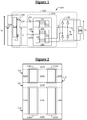
- the resonant electrical circuit 116 firstly comprises a magnetic core 118.
- the magnetic core is for example made of ferrite material.
- the magnetic core 118 has a bottom portion 120 in the shape of "E", an upper portion 122 in the shape of "E” and a central portion 124 in the shape of "I".
- the lower portion 120 comprises first a vertical left leg 120G, a vertical vertical leg 120C and a vertical leg 120D straight, all three rectilinear and parallel to each other.
- the lower portion 120 further comprises a horizontal leg 120T which is rectilinear and perpendicular to the three vertical branches 120G, 120C, 120D. Three first respective ends of the three vertical branches 120G, 120C, 120D join the horizontal branch 120T.
- the upper part 122 comprises firstly a vertical left leg 122G, a central vertical branch 122C and a vertical straight leg 122D, all three rectilinear and parallel to each other.
- the upper part 122 further comprises a horizontal branch 122T which is rectilinear and perpendicular to the three vertical branches 122G, 122C, 122D.
- Three first respective ends of the three vertical branches 122G, 122C, 122D join the horizontal branch 122T.
- the central portion 124 comprises a horizontal branch 124T rectilinear and perpendicular to the three vertical branches 120G, 120C, 120D of the lower part 120 and the three vertical branches 122G, 122C, 122D of the upper part 122.
- Three respective second ends of the three vertical branches 120G, 120C, 120D of the first portion 120 and three respective second ends of the three vertical branches 122G, 122C, 122D of the upper portion 122 join the horizontal branch 124T.
- the central portion 124 closes both the upper portion 122 and the lower portion 120 of the magnetic core.
- the left vertical branches 120G, 122G are in continuity of one another.
- the central vertical branches 120C, 122C are in continuity of one another.
- the straight vertical branches 120D, 122D are in continuity with one another.
- the magnetic core 118 has axial symmetry with respect to a vertical axis centered on the central vertical branches 120C, 122C.
- the lower portion 120 and the central portion 124 define two closed magnetic circuits 126G, 126D closed loop.
- the central portion 124 has a lower reluctance, preferably at least ten times less, more preferably at least one hundred times lower, the reluctance of the lower portion 120 along each lower magnetic circuit 126G, 126D.
- the upper part 122 and the central part 124 define two closed loop-shaped upper magnetic circuits 128G, 128D.
- the central portion 124 has a lower reluctance, preferably at least ten times lower, more preferably at least a hundred times lower, than the reluctance of the upper portion 122 along each upper magnetic circuit 128G, 128D.
- the resonant electrical circuit 116 further comprises a first coil 130 and a second coil 132 wound around the central vertical leg 120C of the lower part 120.
- the coils 130, 132 are strongly coupled to one another, which results in a coupling coefficient k greater than or equal to 0.9, preferably greater than or equal to 0.95, more preferably greater than or equal to 0.99.
- the resonant electrical circuit 116 further comprises a third coil 134 wound around the central vertical branch 122C of the upper part 122.
- the resonant electrical circuit 116 further comprises a capacitor 136 connected in series with the coils 132, 134.
- the electrical converter 102 further includes a rectifier 138 adapted to provide the output voltage Vs from the alternating current ia.
- the rectifier 138 comprises a diode bridge 140 and a smoothing capacitor 142.
- the diode bridge 140 is connected at the input to both ends of the coil 130, and at the output terminals across the capacitor smoothing 142 and electric charge 106.
- the resonant electrical circuit 116 is shown with a circuit diagram equivalent to the magnetic core 118 and the coils 130, 132, 134.
- the coils 130, 132 form an ideal transformer T and a magnetizing inductor Lm at the primary of the ideal transformer T.
- the value of the magnetizing inductance Lm is defined in particular by the width of the gap e2.
- the third coil 134 forms a series inductor Lr.
- the value of the series inductance Lr is defined in particular by the width of the gap e1.
- the shape of the magnetic core 118 has been described on the Figures 1 and 2 by decomposing the latter into three parts 120, 122, 124, this does not mean that the magnetic core 118 is always obtained by the assembly of three parts corresponding to these three parts 120, 122, 124.
- the magnetic core 118 is obtained by the assembly of three mechanical parts 402, 404, 406 shaped "E" each having a transverse bar from which two side bars and a central bar.
- the parts 402, 404 are assembled opposite one another so that their side and central bars are respectively aligned. In addition, the free ends of their lateral bars meet.
- the central bar of at least one of the pieces 402, 404 is shorter than the lateral bars surrounding it so that the central bars of the pieces 402, 404 have ends facing each other at a distance from one another. other so as to form an air gap e2 (" air-gap" in English).
- the piece 406 is assembled against the transverse bar of the piece 404 so that its lateral bars meet the transverse bar of the piece 404.
- the central bar of the piece 406 is shorter than the lateral bars surrounding it so that the free end of the central bar of the workpiece 406 stops at a distance from the transverse bar of the workpiece 404 so as to form an air gap e1 (" air-gap" in English).
- the upper part 122 of the magnetic core 118 is formed by the part 406 and the gap e1.
- the central portion 124 of the magnetic core 118 is formed by the cross bar of the workpiece 404.
- the lower portion 120 of the magnetic core 118 is formed by the workpiece 402, the side and central bars of the workpiece 404 and the air gap e2.
- Each of the air gaps e1, e2 can be left filled with air, or it can be filled with a material of low permeability (maximum relative permeability less than 100).
- the coil 130 may be wound around the coil 132, in order to improve the coupling between them.
- the coil 132 is intended to generate a magnetic flux 302 in the lower 120 and central 124 portions of the magnetic core 118, while the coil 134 is intended to generate a magnetic flux 304 in the upper 122 and central 124 of the magnetic core.
- the magnetic fluxes 302, 304 loop through this central part 124.
- the coil 134 is magnetically isolated from the coils 130, 132, so that the transformer formed by the coils 130, 132 and the series inductor Lr formed by the coil 134 operate independently of one another.
- the winding direction of the coils 132, 134 is chosen so that the magnetic fluxes 302, 304 traverse the central portion 124 in opposite directions. Thus, the resulting magnetic flux 306 in the central portion 124 remains low.
- the coils 132, 134 are wound in the same direction of rotation.
- the coils 130, 132, 134 are preferably made with Litz wire, which makes it possible to reduce the eddy current losses. Nevertheless, other types of conductor could be used, such as round conductors or copper plates.
- the resulting magnetic flux 306 is lower than the other two magnetic fluxes 302, 304.
- the losses in the central portion 124 of the magnetic core 118 are reduced and the risk of occurrence of a hot spot is also reduced.
- the cross section of the central portion 124 is reduced, which makes it possible to improve the compactness of the resonant electrical circuit 116.
- the transformer formed by the coils 130, 132 and the coil 134 share the same magnetic core, and in particular the central portion 124, less magnetic core is used.
- the voltage generator 108 generates the variable voltage V square, by cutting the input voltage Ve at a desired frequency.
- variable voltage V is applied across the capacitors 136, and the coils 132, 134 which are therefore excited at the frequency of the variable voltage V. In response to this excitation, the alternating current i appears in the coil 130.
- the rectifier 140 rectifies the alternating current ia and supplies the rectified current to the electric load 106 and the smoothing capacitance 142, the latter smoothing the output voltage Vs so that it is continuous.
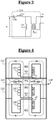
- the magnetic core 118 no longer has an air gap.
- Parts 120, 122, 124 are made by assembling three corresponding parts, and therefore designated by the same references.
- the parts 120, 122 are made of a material of low permeability (maximum relative permeability less than 100) such as powdered metals (English “powdered metal” ), while the piece 124 is made of a strong material.
- permeability maximum relative permeability greater than 100, preferably greater than 1000).
- the rectifier 138 is connected in central tap (from the English "center-tap") to the coil 130. More specifically, a terminal of the smoothing capacitor 142 and the electric load 106 is connected to a point the middle of the coil 130, while the other terminal of the smoothing capacitance 142 and the electric charge 106 is connected to both ends of the coil 130 through respectively two diodes 602, 604 passing the current from the coil 130.
- the magnetic fields escape from the magnetic core 118 at the air gaps e1, e2.
- these air gaps e1, e2 are formed in the central branches 120C, 122C which are surrounded by right and left arms 120G, 122G, 120D, 122D, this escaped magnetic field remains in the bulk of the magnetic core 118 and therefore does not risk disturbing surrounding electrical components.
- the EMC electromagnétique compatibility
- the particular shape of the magnetic core 118 makes it possible to manufacture it very easily, either with three pieces in the shape of "E” ( figure 4 ) with two "E” shaped pieces and one "I” shaped piece ( figure 6 ).
Landscapes
- Engineering & Computer Science (AREA)
- Power Engineering (AREA)
- Chemical & Material Sciences (AREA)
- Composite Materials (AREA)
- Mechanical Engineering (AREA)
- Inverter Devices (AREA)
- Dc-Dc Converters (AREA)
- Coils Or Transformers For Communication (AREA)
- Coils Of Transformers For General Uses (AREA)
Applications Claiming Priority (1)
| Application Number | Priority Date | Filing Date | Title |
|---|---|---|---|
| FR1653154A FR3050069B1 (fr) | 2016-04-08 | 2016-04-08 | Composant magnetique, circuit electrique resonant, convertisseur electrique et systeme electrique |
Publications (2)
| Publication Number | Publication Date |
|---|---|
| EP3229247A1 true EP3229247A1 (de) | 2017-10-11 |
| EP3229247B1 EP3229247B1 (de) | 2019-01-02 |
Family
ID=56373011
Family Applications (1)
| Application Number | Title | Priority Date | Filing Date |
|---|---|---|---|
| EP17164096.4A Active EP3229247B1 (de) | 2016-04-08 | 2017-03-31 | Magnetkomponente, elektrischer resonanzschaltkreis, stromwandler und elektrisches system |
Country Status (5)
| Country | Link |
|---|---|
| US (1) | US11205537B2 (de) |
| EP (1) | EP3229247B1 (de) |
| JP (2) | JP2017191936A (de) |
| CN (1) | CN107275053B (de) |
| FR (1) | FR3050069B1 (de) |
Cited By (2)
| Publication number | Priority date | Publication date | Assignee | Title |
|---|---|---|---|---|
| US12095320B2 (en) | 2022-06-27 | 2024-09-17 | Anthropocene Institute LLC | Axial flux switched reluctance and inductance state machine systems, devices, and methods |
| US12149134B2 (en) | 2022-06-27 | 2024-11-19 | Anthropocene Institute LLC | Axial flux switched reluctance motor and generator, and related systems and methods |
Families Citing this family (3)
| Publication number | Priority date | Publication date | Assignee | Title |
|---|---|---|---|---|
| CN108538552A (zh) * | 2018-01-22 | 2018-09-14 | 许继电源有限公司 | 一种集成谐振电感的磁芯装置及其变压器 |
| GB2598365A (en) * | 2020-08-28 | 2022-03-02 | Eaton Intelligent Power Ltd | Current controlling element based on saturation of a magnetic circuit |
| DE102021202977A1 (de) | 2021-03-26 | 2022-09-29 | Vitesco Technologies Germany Gmbh | Transformator-Anordnung, Gleichspannungswandler mit einer Transformator-Anordnung |
Citations (5)
| Publication number | Priority date | Publication date | Assignee | Title |
|---|---|---|---|---|
| US2137433A (en) * | 1934-02-06 | 1938-11-22 | Wirz Emil | Control device for electric transformers |
| FR2134409A1 (de) * | 1971-04-23 | 1972-12-08 | Westinghouse Electric Corp | |
| US4206434A (en) * | 1978-08-28 | 1980-06-03 | Hase A M | Regulating transformer with magnetic shunt |
| GB2254202A (en) * | 1991-03-19 | 1992-09-30 | Kijima Co Ltd | Electric converter |
| US20090303652A1 (en) * | 2008-06-09 | 2009-12-10 | Tallam Rangarajan M | Method and apparatus for reducing differential mode and common mode reflections in motor drives |
Family Cites Families (31)
| Publication number | Priority date | Publication date | Assignee | Title |
|---|---|---|---|---|
| JPS5331222U (de) * | 1976-08-25 | 1978-03-17 | ||
| US5469053A (en) * | 1992-11-02 | 1995-11-21 | A - Tech Corporation | E/U core linear variable differential transformer for precise displacement measurement |
| US6456069B1 (en) * | 1999-03-05 | 2002-09-24 | The United States Of America As Represented By The Secretary Of The Navy | Fluxgate magnetic field sensor incorporating ferromagnetic test material into its magnetic circuitry |
| JP2001268906A (ja) * | 2000-03-01 | 2001-09-28 | Delphi Technol Inc | サブ共振dc−dcコンバータを有するデュアル電圧自動車両電気システム |
| JPWO2002021543A1 (ja) * | 2000-09-08 | 2004-01-15 | Necトーキン株式会社 | 永久磁石、それを磁気バイアス用磁石とした磁気コア、およびそれを用いたインダクタンス部品 |
| TWI239538B (en) * | 2004-03-25 | 2005-09-11 | Darfon Electronics Corp | Transformer and lamp driving system using the same |
| US7136293B2 (en) * | 2004-06-24 | 2006-11-14 | Petkov Roumen D | Full wave series resonant type DC to DC power converter with integrated magnetics |
| TWI284331B (en) * | 2005-02-05 | 2007-07-21 | Darfon Electronics Corp | Transformer and multi-lamp driving circuit using the same |
| JP2006311743A (ja) * | 2005-04-28 | 2006-11-09 | Sony Corp | スイッチング電源回路 |
| JP4482765B2 (ja) * | 2005-09-30 | 2010-06-16 | Tdk株式会社 | スイッチング電源装置 |
| TW200721207A (en) * | 2005-11-28 | 2007-06-01 | Ind Tech Res Inst | Detachable transformer for contactless power supply system |
| TWI278876B (en) * | 2006-01-03 | 2007-04-11 | Delta Electronics Inc | Transformer structure |
| KR20070074059A (ko) * | 2006-01-06 | 2007-07-12 | 삼성전자주식회사 | 자기 코어 및 이를 포함하는 인덕터, 변압기 |
| CN100570768C (zh) * | 2006-02-08 | 2009-12-16 | 台达电子工业股份有限公司 | 变压器结构 |
| JP2008205466A (ja) * | 2007-02-17 | 2008-09-04 | Zhejiang Univ | 磁気部品 |
| US8058830B2 (en) * | 2007-07-30 | 2011-11-15 | GM Global Technology Operations LLC | Charging energy sources with a rectifier using double-ended inverter system |
| JP2009059995A (ja) * | 2007-09-03 | 2009-03-19 | Fuji Electric Systems Co Ltd | 複合磁気部品 |
| JP2009176989A (ja) * | 2008-01-25 | 2009-08-06 | Panasonic Corp | 共振型スイッチング電源回路用トランスユニット |
| JP2009239219A (ja) * | 2008-03-28 | 2009-10-15 | Taiyo Yuden Co Ltd | 複合トランス |
| JP2010171225A (ja) * | 2009-01-23 | 2010-08-05 | Shindengen Electric Mfg Co Ltd | トランスおよびスイッチング電源 |
| JP2011082205A (ja) * | 2009-10-02 | 2011-04-21 | Sumitomo Electric Ind Ltd | トランス装置及びこのトランス装置を備えた変換器 |
| CN102056383B (zh) * | 2009-10-30 | 2013-06-05 | 国琏电子(上海)有限公司 | 多灯管驱动系统 |
| JP5474893B2 (ja) * | 2010-08-31 | 2014-04-16 | サムソン エレクトロ−メカニックス カンパニーリミテッド. | インダクター一体型トランスフォーマー |
| GB201105077D0 (en) * | 2011-03-25 | 2011-05-11 | Redisem Ltd | Transformer for resonant converters |
| JP5830915B2 (ja) * | 2011-04-26 | 2015-12-09 | 株式会社デンソー | 電力変換回路 |
| CN102149243B (zh) * | 2011-05-19 | 2016-02-03 | 福州大学 | 一种可用于多路led驱动的反激式磁集成变换器 |
| JP5887886B2 (ja) * | 2011-11-30 | 2016-03-16 | 株式会社デンソー | 複合磁気部品 |
| JP6120623B2 (ja) * | 2013-03-15 | 2017-04-26 | オムロンオートモーティブエレクトロニクス株式会社 | 磁気デバイス |
| JP5790700B2 (ja) * | 2013-04-15 | 2015-10-07 | 株式会社デンソー | フィルタ部品 |
| CN203397878U (zh) * | 2013-09-01 | 2014-01-15 | 兰州交通大学 | 一种变压器式可控电抗器磁集成装置 |
| TWI557759B (zh) * | 2015-04-10 | 2016-11-11 | 台達電子工業股份有限公司 | 集成式電感及其集成式電感磁芯 |
-
2016
- 2016-04-08 FR FR1653154A patent/FR3050069B1/fr active Active
-
2017
- 2017-03-31 EP EP17164096.4A patent/EP3229247B1/de active Active
- 2017-04-07 CN CN201710223513.2A patent/CN107275053B/zh active Active
- 2017-04-07 JP JP2017076650A patent/JP2017191936A/ja active Pending
- 2017-04-07 US US15/482,164 patent/US11205537B2/en not_active Expired - Fee Related
-
2022
- 2022-06-21 JP JP2022099496A patent/JP2022137082A/ja active Pending
Patent Citations (5)
| Publication number | Priority date | Publication date | Assignee | Title |
|---|---|---|---|---|
| US2137433A (en) * | 1934-02-06 | 1938-11-22 | Wirz Emil | Control device for electric transformers |
| FR2134409A1 (de) * | 1971-04-23 | 1972-12-08 | Westinghouse Electric Corp | |
| US4206434A (en) * | 1978-08-28 | 1980-06-03 | Hase A M | Regulating transformer with magnetic shunt |
| GB2254202A (en) * | 1991-03-19 | 1992-09-30 | Kijima Co Ltd | Electric converter |
| US20090303652A1 (en) * | 2008-06-09 | 2009-12-10 | Tallam Rangarajan M | Method and apparatus for reducing differential mode and common mode reflections in motor drives |
Non-Patent Citations (2)
| Title |
|---|
| DE SIMONE ET AL., DESIGN GUIDELINE FOR MAGNETIC INTÉGRATION IN LLC RÉSONANT CONVERTERS, 2008 |
| POWER ELECTRONICS, ELECTRICAL DRIVES, AUTOMATION AND MOTION, 2008 |
Cited By (3)
| Publication number | Priority date | Publication date | Assignee | Title |
|---|---|---|---|---|
| US12095320B2 (en) | 2022-06-27 | 2024-09-17 | Anthropocene Institute LLC | Axial flux switched reluctance and inductance state machine systems, devices, and methods |
| US12149134B2 (en) | 2022-06-27 | 2024-11-19 | Anthropocene Institute LLC | Axial flux switched reluctance motor and generator, and related systems and methods |
| US12580465B2 (en) | 2022-06-27 | 2026-03-17 | Anthropocene Institute LLC | Axial flux switched reluctance and inductance state machine systems, devices, and methods |
Also Published As
| Publication number | Publication date |
|---|---|
| JP2017191936A (ja) | 2017-10-19 |
| JP2022137082A (ja) | 2022-09-21 |
| CN107275053A (zh) | 2017-10-20 |
| US11205537B2 (en) | 2021-12-21 |
| CN107275053B (zh) | 2022-03-29 |
| FR3050069A1 (fr) | 2017-10-13 |
| EP3229247B1 (de) | 2019-01-02 |
| US20170294259A1 (en) | 2017-10-12 |
| FR3050069B1 (fr) | 2018-05-11 |
Similar Documents
| Publication | Publication Date | Title |
|---|---|---|
| EP3229247B1 (de) | Magnetkomponente, elektrischer resonanzschaltkreis, stromwandler und elektrisches system | |
| CA2872711C (fr) | Transformateur tournant triphase a flux lies libre | |
| WO2017055739A1 (fr) | Transformateur redresseur dodécaphasé | |
| EP4189712A1 (de) | Magnetische komponente mit gesteuertem streufluss | |
| EP3275004B1 (de) | Dreiphasiger transformator für zwölfphasigen gleichrichter | |
| EP2834820B1 (de) | Fixer dreiphasen-zu-zweiphasen-transformator mit zwangsverknüpftem fluss | |
| WO2017140674A1 (fr) | Composant magnétique, circuit electrique resonant, convertisseur electrique et systeme electrique | |
| EP1019926B1 (de) | Induktives bauelement und verfahren zur herstellung eines solchen bauelements | |
| EP3198617B1 (de) | Magnetkern eines rotierenden transformators | |
| EP3758031A1 (de) | Elektrischer transformator mit einer kontrollierten verteilung der streuinduktivität | |
| EP3678151B1 (de) | Mehrphasiger induktiver filter | |
| EP4174884A1 (de) | Innovative struktur einer planaren elektromagnetischen komponente | |
| WO2021116632A1 (fr) | Dispositif électrotechnique pour un aéronef | |
| EP0727794B1 (de) | Transformator, insbesondere für Energiewandler, und Resonanzenergiewandler mit einem solchen Transformator | |
| WO2021116599A1 (fr) | Dispositif électrotechnique pour un aéronef comprenant des composants bobinés basse fréquence | |
| FR3112887A1 (fr) | Ensemble comprenant au moins une première et une deuxième inductance en couplage magnétique partiel | |
| BE900164A (fr) | Machine electrique transformatrice de tension, pouvant etre commandee. | |
| WO2022106370A1 (fr) | Dispositif electrique a deux groupes de bobines couplees portes par un carte de circuit imprime, convertisseur de tension comportant un tel dispositif electrique et procede de fabrication d'un tel dispositif electrique | |
| FR3081254A1 (fr) | Bobine planaire et procede de fabrication d’une bobine planaire | |
| Cividjian | Optimal shading coil cross-section for minimal ripple factor of AC electromagnet attracting force | |
| FR3112886A1 (fr) | Ensemble comprenant au moins une première et une deuxième inductance | |
| EP3257062A1 (de) | Als multipler magnetkreis konfigurierte elektromagnetische induktionsvorrichtung | |
| EP4725036A1 (de) | Elektromagnetische induktionsvorrichtung | |
| FR2962251A1 (fr) | Dispositif de connexion sans contact electrique permettant la transmission d'une puissance electrique | |
| FR3004602A1 (fr) | Convertisseur de tension et procede de conversion de tension |
Legal Events
| Date | Code | Title | Description |
|---|---|---|---|
| PUAI | Public reference made under article 153(3) epc to a published international application that has entered the european phase |
Free format text: ORIGINAL CODE: 0009012 |
|
| STAA | Information on the status of an ep patent application or granted ep patent |
Free format text: STATUS: THE APPLICATION HAS BEEN PUBLISHED |
|
| AK | Designated contracting states |
Kind code of ref document: A1 Designated state(s): AL AT BE BG CH CY CZ DE DK EE ES FI FR GB GR HR HU IE IS IT LI LT LU LV MC MK MT NL NO PL PT RO RS SE SI SK SM TR |
|
| AX | Request for extension of the european patent |
Extension state: BA ME |
|
| STAA | Information on the status of an ep patent application or granted ep patent |
Free format text: STATUS: REQUEST FOR EXAMINATION WAS MADE |
|
| 17P | Request for examination filed |
Effective date: 20180409 |
|
| RBV | Designated contracting states (corrected) |
Designated state(s): AL AT BE BG CH CY CZ DE DK EE ES FI FR GB GR HR HU IE IS IT LI LT LU LV MC MK MT NL NO PL PT RO RS SE SI SK SM TR |
|
| GRAP | Despatch of communication of intention to grant a patent |
Free format text: ORIGINAL CODE: EPIDOSNIGR1 |
|
| STAA | Information on the status of an ep patent application or granted ep patent |
Free format text: STATUS: GRANT OF PATENT IS INTENDED |
|
| GRAJ | Information related to disapproval of communication of intention to grant by the applicant or resumption of examination proceedings by the epo deleted |
Free format text: ORIGINAL CODE: EPIDOSDIGR1 |
|
| RIC1 | Information provided on ipc code assigned before grant |
Ipc: H01F 30/12 20060101AFI20180516BHEP Ipc: H01F 3/10 20060101ALI20180516BHEP |
|
| GRAP | Despatch of communication of intention to grant a patent |
Free format text: ORIGINAL CODE: EPIDOSNIGR1 |
|
| STAA | Information on the status of an ep patent application or granted ep patent |
Free format text: STATUS: REQUEST FOR EXAMINATION WAS MADE |
|
| GRAJ | Information related to disapproval of communication of intention to grant by the applicant or resumption of examination proceedings by the epo deleted |
Free format text: ORIGINAL CODE: EPIDOSDIGR1 |
|
| INTG | Intention to grant announced |
Effective date: 20180615 |
|
| RAP1 | Party data changed (applicant data changed or rights of an application transferred) |
Owner name: VALEO SYSTEMES DE CONTROLE MOTEUR |
|
| INTC | Intention to grant announced (deleted) | ||
| GRAP | Despatch of communication of intention to grant a patent |
Free format text: ORIGINAL CODE: EPIDOSNIGR1 |
|
| STAA | Information on the status of an ep patent application or granted ep patent |
Free format text: STATUS: GRANT OF PATENT IS INTENDED |
|
| INTG | Intention to grant announced |
Effective date: 20181002 |
|
| GRAS | Grant fee paid |
Free format text: ORIGINAL CODE: EPIDOSNIGR3 |
|
| GRAA | (expected) grant |
Free format text: ORIGINAL CODE: 0009210 |
|
| STAA | Information on the status of an ep patent application or granted ep patent |
Free format text: STATUS: THE PATENT HAS BEEN GRANTED |
|
| AK | Designated contracting states |
Kind code of ref document: B1 Designated state(s): AL AT BE BG CH CY CZ DE DK EE ES FI FR GB GR HR HU IE IS IT LI LT LU LV MC MK MT NL NO PL PT RO RS SE SI SK SM TR |
|
| REG | Reference to a national code |
Ref country code: GB Ref legal event code: FG4D Free format text: NOT ENGLISH |
|
| REG | Reference to a national code |
Ref country code: CH Ref legal event code: EP Ref country code: AT Ref legal event code: REF Ref document number: 1085424 Country of ref document: AT Kind code of ref document: T Effective date: 20190115 |
|
| REG | Reference to a national code |
Ref country code: IE Ref legal event code: FG4D Free format text: LANGUAGE OF EP DOCUMENT: FRENCH |
|
| REG | Reference to a national code |
Ref country code: DE Ref legal event code: R096 Ref document number: 602017001632 Country of ref document: DE |
|
| RAP2 | Party data changed (patent owner data changed or rights of a patent transferred) |
Owner name: VALEO SIEMENS EAUTOMOTIVE FRANCE SAS |
|
| REG | Reference to a national code |
Ref country code: NL Ref legal event code: MP Effective date: 20190102 |
|
| REG | Reference to a national code |
Ref country code: LT Ref legal event code: MG4D |
|
| REG | Reference to a national code |
Ref country code: AT Ref legal event code: MK05 Ref document number: 1085424 Country of ref document: AT Kind code of ref document: T Effective date: 20190102 |
|
| PG25 | Lapsed in a contracting state [announced via postgrant information from national office to epo] |
Ref country code: NL Free format text: LAPSE BECAUSE OF FAILURE TO SUBMIT A TRANSLATION OF THE DESCRIPTION OR TO PAY THE FEE WITHIN THE PRESCRIBED TIME-LIMIT Effective date: 20190102 |
|
| PG25 | Lapsed in a contracting state [announced via postgrant information from national office to epo] |
Ref country code: PT Free format text: LAPSE BECAUSE OF FAILURE TO SUBMIT A TRANSLATION OF THE DESCRIPTION OR TO PAY THE FEE WITHIN THE PRESCRIBED TIME-LIMIT Effective date: 20190502 Ref country code: SE Free format text: LAPSE BECAUSE OF FAILURE TO SUBMIT A TRANSLATION OF THE DESCRIPTION OR TO PAY THE FEE WITHIN THE PRESCRIBED TIME-LIMIT Effective date: 20190102 Ref country code: FI Free format text: LAPSE BECAUSE OF FAILURE TO SUBMIT A TRANSLATION OF THE DESCRIPTION OR TO PAY THE FEE WITHIN THE PRESCRIBED TIME-LIMIT Effective date: 20190102 Ref country code: NO Free format text: LAPSE BECAUSE OF FAILURE TO SUBMIT A TRANSLATION OF THE DESCRIPTION OR TO PAY THE FEE WITHIN THE PRESCRIBED TIME-LIMIT Effective date: 20190402 Ref country code: PL Free format text: LAPSE BECAUSE OF FAILURE TO SUBMIT A TRANSLATION OF THE DESCRIPTION OR TO PAY THE FEE WITHIN THE PRESCRIBED TIME-LIMIT Effective date: 20190102 Ref country code: ES Free format text: LAPSE BECAUSE OF FAILURE TO SUBMIT A TRANSLATION OF THE DESCRIPTION OR TO PAY THE FEE WITHIN THE PRESCRIBED TIME-LIMIT Effective date: 20190102 Ref country code: LT Free format text: LAPSE BECAUSE OF FAILURE TO SUBMIT A TRANSLATION OF THE DESCRIPTION OR TO PAY THE FEE WITHIN THE PRESCRIBED TIME-LIMIT Effective date: 20190102 |
|
| PG25 | Lapsed in a contracting state [announced via postgrant information from national office to epo] |
Ref country code: IS Free format text: LAPSE BECAUSE OF FAILURE TO SUBMIT A TRANSLATION OF THE DESCRIPTION OR TO PAY THE FEE WITHIN THE PRESCRIBED TIME-LIMIT Effective date: 20190502 Ref country code: GR Free format text: LAPSE BECAUSE OF FAILURE TO SUBMIT A TRANSLATION OF THE DESCRIPTION OR TO PAY THE FEE WITHIN THE PRESCRIBED TIME-LIMIT Effective date: 20190403 Ref country code: LV Free format text: LAPSE BECAUSE OF FAILURE TO SUBMIT A TRANSLATION OF THE DESCRIPTION OR TO PAY THE FEE WITHIN THE PRESCRIBED TIME-LIMIT Effective date: 20190102 Ref country code: HR Free format text: LAPSE BECAUSE OF FAILURE TO SUBMIT A TRANSLATION OF THE DESCRIPTION OR TO PAY THE FEE WITHIN THE PRESCRIBED TIME-LIMIT Effective date: 20190102 Ref country code: BG Free format text: LAPSE BECAUSE OF FAILURE TO SUBMIT A TRANSLATION OF THE DESCRIPTION OR TO PAY THE FEE WITHIN THE PRESCRIBED TIME-LIMIT Effective date: 20190402 Ref country code: RS Free format text: LAPSE BECAUSE OF FAILURE TO SUBMIT A TRANSLATION OF THE DESCRIPTION OR TO PAY THE FEE WITHIN THE PRESCRIBED TIME-LIMIT Effective date: 20190102 |
|
| REG | Reference to a national code |
Ref country code: DE Ref legal event code: R097 Ref document number: 602017001632 Country of ref document: DE |
|
| PG25 | Lapsed in a contracting state [announced via postgrant information from national office to epo] |
Ref country code: CZ Free format text: LAPSE BECAUSE OF FAILURE TO SUBMIT A TRANSLATION OF THE DESCRIPTION OR TO PAY THE FEE WITHIN THE PRESCRIBED TIME-LIMIT Effective date: 20190102 Ref country code: RO Free format text: LAPSE BECAUSE OF FAILURE TO SUBMIT A TRANSLATION OF THE DESCRIPTION OR TO PAY THE FEE WITHIN THE PRESCRIBED TIME-LIMIT Effective date: 20190102 Ref country code: IT Free format text: LAPSE BECAUSE OF FAILURE TO SUBMIT A TRANSLATION OF THE DESCRIPTION OR TO PAY THE FEE WITHIN THE PRESCRIBED TIME-LIMIT Effective date: 20190102 Ref country code: EE Free format text: LAPSE BECAUSE OF FAILURE TO SUBMIT A TRANSLATION OF THE DESCRIPTION OR TO PAY THE FEE WITHIN THE PRESCRIBED TIME-LIMIT Effective date: 20190102 Ref country code: DK Free format text: LAPSE BECAUSE OF FAILURE TO SUBMIT A TRANSLATION OF THE DESCRIPTION OR TO PAY THE FEE WITHIN THE PRESCRIBED TIME-LIMIT Effective date: 20190102 Ref country code: AT Free format text: LAPSE BECAUSE OF FAILURE TO SUBMIT A TRANSLATION OF THE DESCRIPTION OR TO PAY THE FEE WITHIN THE PRESCRIBED TIME-LIMIT Effective date: 20190102 Ref country code: MC Free format text: LAPSE BECAUSE OF FAILURE TO SUBMIT A TRANSLATION OF THE DESCRIPTION OR TO PAY THE FEE WITHIN THE PRESCRIBED TIME-LIMIT Effective date: 20190102 Ref country code: AL Free format text: LAPSE BECAUSE OF FAILURE TO SUBMIT A TRANSLATION OF THE DESCRIPTION OR TO PAY THE FEE WITHIN THE PRESCRIBED TIME-LIMIT Effective date: 20190102 Ref country code: SK Free format text: LAPSE BECAUSE OF FAILURE TO SUBMIT A TRANSLATION OF THE DESCRIPTION OR TO PAY THE FEE WITHIN THE PRESCRIBED TIME-LIMIT Effective date: 20190102 |
|
| PLBE | No opposition filed within time limit |
Free format text: ORIGINAL CODE: 0009261 |
|
| STAA | Information on the status of an ep patent application or granted ep patent |
Free format text: STATUS: NO OPPOSITION FILED WITHIN TIME LIMIT |
|
| PG25 | Lapsed in a contracting state [announced via postgrant information from national office to epo] |
Ref country code: SM Free format text: LAPSE BECAUSE OF FAILURE TO SUBMIT A TRANSLATION OF THE DESCRIPTION OR TO PAY THE FEE WITHIN THE PRESCRIBED TIME-LIMIT Effective date: 20190102 Ref country code: LU Free format text: LAPSE BECAUSE OF NON-PAYMENT OF DUE FEES Effective date: 20190331 |
|
| 26N | No opposition filed |
Effective date: 20191003 |
|
| REG | Reference to a national code |
Ref country code: BE Ref legal event code: MM Effective date: 20190331 |
|
| PG25 | Lapsed in a contracting state [announced via postgrant information from national office to epo] |
Ref country code: IE Free format text: LAPSE BECAUSE OF NON-PAYMENT OF DUE FEES Effective date: 20190331 |
|
| PG25 | Lapsed in a contracting state [announced via postgrant information from national office to epo] |
Ref country code: SI Free format text: LAPSE BECAUSE OF FAILURE TO SUBMIT A TRANSLATION OF THE DESCRIPTION OR TO PAY THE FEE WITHIN THE PRESCRIBED TIME-LIMIT Effective date: 20190102 Ref country code: BE Free format text: LAPSE BECAUSE OF NON-PAYMENT OF DUE FEES Effective date: 20190331 |
|
| PG25 | Lapsed in a contracting state [announced via postgrant information from national office to epo] |
Ref country code: TR Free format text: LAPSE BECAUSE OF FAILURE TO SUBMIT A TRANSLATION OF THE DESCRIPTION OR TO PAY THE FEE WITHIN THE PRESCRIBED TIME-LIMIT Effective date: 20190102 |
|
| PG25 | Lapsed in a contracting state [announced via postgrant information from national office to epo] |
Ref country code: MT Free format text: LAPSE BECAUSE OF FAILURE TO SUBMIT A TRANSLATION OF THE DESCRIPTION OR TO PAY THE FEE WITHIN THE PRESCRIBED TIME-LIMIT Effective date: 20190102 |
|
| REG | Reference to a national code |
Ref country code: DE Ref legal event code: R081 Ref document number: 602017001632 Country of ref document: DE Owner name: VALEO SIEMENS EAUTOMOTIVE FRANCE SAS, FR Free format text: FORMER OWNER: VALEO SYSTEMES DE CONTROLE MOTEUR, CERGY PONTOISE, FR |
|
| REG | Reference to a national code |
Ref country code: CH Ref legal event code: PL |
|
| PG25 | Lapsed in a contracting state [announced via postgrant information from national office to epo] |
Ref country code: LI Free format text: LAPSE BECAUSE OF NON-PAYMENT OF DUE FEES Effective date: 20200331 Ref country code: CH Free format text: LAPSE BECAUSE OF NON-PAYMENT OF DUE FEES Effective date: 20200331 |
|
| PG25 | Lapsed in a contracting state [announced via postgrant information from national office to epo] |
Ref country code: CY Free format text: LAPSE BECAUSE OF FAILURE TO SUBMIT A TRANSLATION OF THE DESCRIPTION OR TO PAY THE FEE WITHIN THE PRESCRIBED TIME-LIMIT Effective date: 20190102 |
|
| PG25 | Lapsed in a contracting state [announced via postgrant information from national office to epo] |
Ref country code: HU Free format text: LAPSE BECAUSE OF FAILURE TO SUBMIT A TRANSLATION OF THE DESCRIPTION OR TO PAY THE FEE WITHIN THE PRESCRIBED TIME-LIMIT; INVALID AB INITIO Effective date: 20170331 |
|
| GBPC | Gb: european patent ceased through non-payment of renewal fee |
Effective date: 20210331 |
|
| PG25 | Lapsed in a contracting state [announced via postgrant information from national office to epo] |
Ref country code: GB Free format text: LAPSE BECAUSE OF NON-PAYMENT OF DUE FEES Effective date: 20210331 |
|
| PG25 | Lapsed in a contracting state [announced via postgrant information from national office to epo] |
Ref country code: MK Free format text: LAPSE BECAUSE OF FAILURE TO SUBMIT A TRANSLATION OF THE DESCRIPTION OR TO PAY THE FEE WITHIN THE PRESCRIBED TIME-LIMIT Effective date: 20190102 |
|
| P01 | Opt-out of the competence of the unified patent court (upc) registered |
Effective date: 20230629 |
|
| PGFP | Annual fee paid to national office [announced via postgrant information from national office to epo] |
Ref country code: DE Payment date: 20260313 Year of fee payment: 10 |
|
| PGFP | Annual fee paid to national office [announced via postgrant information from national office to epo] |
Ref country code: FR Payment date: 20260331 Year of fee payment: 10 |