EP3229348B1 - Rotor pour machine électrique tournante - Google Patents
Rotor pour machine électrique tournante Download PDFInfo
- Publication number
- EP3229348B1 EP3229348B1 EP17164677.1A EP17164677A EP3229348B1 EP 3229348 B1 EP3229348 B1 EP 3229348B1 EP 17164677 A EP17164677 A EP 17164677A EP 3229348 B1 EP3229348 B1 EP 3229348B1
- Authority
- EP
- European Patent Office
- Prior art keywords
- rotor
- magnets
- axis
- branch
- length
- Prior art date
- Legal status (The legal status is an assumption and is not a legal conclusion. Google has not performed a legal analysis and makes no representation as to the accuracy of the status listed.)
- Active
Links
Images






Classifications
-
- H—ELECTRICITY
- H02—GENERATION; CONVERSION OR DISTRIBUTION OF ELECTRIC POWER
- H02K—DYNAMO-ELECTRIC MACHINES
- H02K1/00—Details of the magnetic circuit
- H02K1/06—Details of the magnetic circuit characterised by the shape, form or construction
- H02K1/22—Rotating parts of the magnetic circuit
- H02K1/27—Rotor cores with permanent magnets
- H02K1/2706—Inner rotors
- H02K1/272—Inner rotors the magnetisation axis of the magnets being perpendicular to the rotor axis
- H02K1/274—Inner rotors the magnetisation axis of the magnets being perpendicular to the rotor axis the rotor consisting of two or more circumferentially positioned magnets
- H02K1/2753—Inner rotors the magnetisation axis of the magnets being perpendicular to the rotor axis the rotor consisting of two or more circumferentially positioned magnets the rotor consisting of magnets or groups of magnets arranged with alternating polarity
- H02K1/276—Magnets embedded in the magnetic core, e.g. interior permanent magnets [IPM]
- H02K1/2766—Magnets embedded in the magnetic core, e.g. interior permanent magnets [IPM] having a flux concentration effect
-
- H—ELECTRICITY
- H02—GENERATION; CONVERSION OR DISTRIBUTION OF ELECTRIC POWER
- H02K—DYNAMO-ELECTRIC MACHINES
- H02K2201/00—Specific aspects not provided for in the other groups of this subclass relating to the magnetic circuits
- H02K2201/06—Magnetic cores, or permanent magnets characterised by their skew
-
- H—ELECTRICITY
- H02—GENERATION; CONVERSION OR DISTRIBUTION OF ELECTRIC POWER
- H02K—DYNAMO-ELECTRIC MACHINES
- H02K2213/00—Specific aspects, not otherwise provided for and not covered by codes H02K2201/00 - H02K2211/00
- H02K2213/03—Machines characterised by numerical values, ranges, mathematical expressions or similar information
Definitions
- the present invention relates to a rotor for a rotating electrical machine and to a rotating electrical machine comprising such a rotor.
- rotating electrical machines comprise two coaxial parts, namely a rotor and a stator surrounding the body of the rotor (Cf. US2002 / 175583 , EP2264860 , US2003 / 127280 , CN102790458 , DE102012205191 )
- the figure 1 shows the structure of a defluxable rotary electrical machine according to the state of the art.
- the machine 11 is of the type with buried magnets and flux concentration and comprises a stator 10 and a rotor 100.
- a concrete embodiment of such a machine is for example a traction motor of 8 to 10 KW for applications in vehicles. automobiles of the so-called “mild-hybrid” type.
- a particular embodiment of this motor comprises a stator 10 having 60 notches 101 and a rotor 100 having 10 alternating North and South poles.
- the rotor 100 has a diameter of the order of 100 mm and an axial length of the order of 50 mm.
- the rotor 100 comprises 10 permanent magnets PM having a substantially rectangular shape and for dimensions: length (Lm) x height (ha) x width (la) 50 mm x 25 mm x 5 mm.
- the stator 10 and the rotor 100 are made with packets of metal sheets forming magnetic masses.
- the notches 101 of the stator 10 are provided to receive stator windings (not shown) and form between them a plurality of stator teeth.
- the notches 101 will thus be provided to accommodate concentrated coils, wound on large teeth, or else distributed coils.
- the rotor 100 has the general shape of a multilobed cylinder, each of the lobes corresponding to a magnetic pole of the rotor.
- An air gap 16 is defined between the stator 10 and the rotor 100.
- the PM magnets are arranged radially. PM magnets are preferably permanent magnets comprising rare earths such as Neodymium-Iron-Boron (NeFeB), Samarium-Iron (SmFe), Samarium-Cobalt (SmCo) type magnets or else magnets obtained from ferrites sintered or bonded.
- the body of the rotor 100 is provided with an X axis and comprises a central bore opening at its two facial ends and intended to receive a drive shaft. It will be noted that in the present invention the drive shaft may be made from a magnetic or non-magnetic material depending on the envisaged application.
- the rotor 100 also comprises recesses E1, E2 and E3 which are repeated for each pole and extend axially over substantially the entire length of the rotor.
- Closure sheets are optionally provided at the facial ends of the rotor 100 in order to help assemble the rotor 100.
- Welding points (not shown) at the periphery of the packet of sheets and through tie rods (not shown), parallel to the central axis, are also provided for the assembly of the rotor 100.
- the tie rods are made of a magnetic or non-magnetic material, depending on the applications.
- the passage of the tie rods through the pack of sheets of the rotor 100 can be done through the recesses E3.
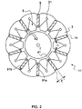
- the figure 2 shows a rotor 100 according to the state of the art, of axis X, having a body 3 fixed to a central hub (not shown) splined at its internal periphery for fixing in rotation on a shaft.
- Body 3 has housings 9 intended to receive permanent magnets 14 held radially and axially by means of retaining devices 17 visible on the figure 3 exerting by deformation a radial force on the magnet 14 as well as on an internal axial part 91a of the housing 9.
- the rotor 100 is formed by a stack of sheets extending in a radial plane perpendicular to the X axis.
- the bundle of sheets forms the body 3 of the rotor 100 and is made of ferromagnetic material.
- the sheets of the body 3 are preferably held by means of rivets axially passing through the rotor 100 right through via openings 31.
- Recesses 5 are made in the body 3. According to a preferred embodiment, these recesses 5 have a shape resulting from the combination of a triangle shape and a trapezoid shape. The triangle has a common side with the large side of the trapezoid. The recesses 5 make it possible to channel the magnetic flux well.
- the housings 9 of the body 3 are preferably of substantially parallelepipedal shape intended to receive the permanent magnets 14. These housings 9 regularly spaced around the circumference of the rotor and located in the body 3 of the rotor 100, have a longitudinal direction of extension parallel to the rotor. X axis and an extension direction extending substantially radially with respect to the X axis.
- the housings 9, formed in the body 3, are here preferably and of generally rectangular section.
- the housing 9 follows a section perpendicular to the X axis and may pass through. Alternatively, the housings 9 can be closed at one of their axial ends.
- the housings 9 are delimited radially by the internal axial part 91a already mentioned and an external axial part 91b.
- the faces of the parts 91b and 91a are respectively oriented radially towards the X axis of the rotor 100 and the side opposite to the X axis of the rotor 100.
- the internal axial part 91a faces outwards from the rotor 100. While the axial part 91b faces towards the inside of the rotor 100.
- the outside of the rotor 100 is formed by the radial wall of the rotor 100 is formed.
- the part of rotor 100 farthest from the X axis and the interior of rotor 100 is the part of rotor 100 that is relatively closest to the center of rotor 100 and the X axis.
- the housings 9 are intended to receive each of the elements in the form of a magnet 14.
- the magnets 14 can be made of rare earth, for example based on Samarium-Cobalt (SmCo) or based on Neodymium-Iron-Boron (NdFeB). having a high coercivity and a high rate of remanence as well as good temperature resistance. They can also be made of ferrite.
- rare earth magnets 14 can be housed in housings 9 and ferrites 9 in other housings, the number of which may be equal to or less than the number of rare earth magnets.
- housings 9 and ferrites 9 in other housings, the number of which may be equal to or less than the number of rare earth magnets.
- expensive rare earth magnets in order to approach as closely as possible, for example, a desired electrical power of the machine and to supplement this with less expensive ferrite magnets.
- the internal axial part 91a of the housing 9 comprises two concave portions 42 and a projecting portion 41 extending axially along the axis X.
- the projecting portion 41 is closer to the face 15 of the magnet than the two portions concave 42.
- the recesses 5 are made in the body 3 and positioned between the housings 9 on a path successively connecting the projecting portions 41 of the consecutive housings 9, preferably along a section perpendicularly cutting the X axis of the rotor 100.
- the recesses 5 s 'extend along a length L.
- the body 3 of the rotor 100 comprising an X axis and provided with two axial end faces 4a and 4b.
- the body of the rotor 3 comprises the housings 9 delimited by the parts 91a and 91b.
- the holding device 17 comprises flaps 30 and 40 allowing the retaining device 17 to be retained by contact on the axial end faces 4b and 4a respectively.
- the magnets 14 have good resistance to centrifugal force thanks to the device 17 which takes up the play due to the manufacturing tolerances of the housings 9 and of the magnets 14.
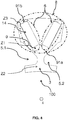
- the figure 4 illustrates a rotor 100 according to the state of the art. It is shown in section along a plane perpendicular to the X axis.
- the rotor 100 comprises a rotor body 3 of axis X.
- the rotor body 3 comprises recesses 5.1 and 5.2 and housings 9.
- Each of the housings 9 is delimited by an internal axial part 91a and an external axial part 91b referenced on the figure 4 .
- Each of the housings 9 receive a magnet 14 respectively.
- the magnets 14 are thus buried in the rotor body 3.
- the group of magnets of two adjacent housings 9 form a V provided with two branches 6.
- the group of V magnets forms a magnetic pole 8 of the rotor 100.
- the rotor 100 comprises other magnetic poles 8 which are alternated around the periphery of the rotor. These poles are intended to interact with the stator 10 of said rotary electrical machine 11. Furthermore, it is defined with reference to figure 4 , 3 zones of the rotor body Z1, Z2 and Z3. According to the rotor 100 of the figure 5 , 14 magnets of size: 6x20x44 mm 3 are provided .
- the magnets used often include rare earths and their cost is very high.
- the resistance to centrifugation of these magnets is demanding.
- the leaks at the end of the magnet can be significant, this is due in particular to the air gap.
- these machines can exhibit torque ripple. These torque ripples can affect the performance of the electrical machine.
- the object of the invention is to respond to this wish while remedying at least one of the aforementioned drawbacks.
- a rotor for an electric machine the rotor being defined by the combination of features of claim 1.
- each branch of said V comprises at least two magnets.
- the at least two magnets are superimposed on part of their lateral faces and are offset in a direction perpendicular to said length. This reduces the torque ripple.
- the field variation levels are reduced, which makes it possible to reduce the eddy current losses in the magnets. It is thus possible, in particular for the same behavior in motor mode of the rotating electric machine, to reduce the quantity of magnet, for example by 10%.
- the branch is segmented along a plane comprising its length so as to form a series of longitudinal segments, the at least two magnets each having the shape of one of the longitudinal segments of said series.
- the at least two magnets are superimposed on part of their longitudinal faces and are offset from one another along the length of the branch.
- the subject of the invention is also a rotary electrical machine which comprises a rotor as described above comprising between 8 and 12 pairs of poles and a stator comprising between 26 and 34 notches surrounding said rotor. It is then an optimized rotating electric machine which provides good efficiency.
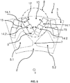
- the figures 5 and 6 illustrate a rotor 1.
- this rotor 1 is shown in section along a plane perpendicular to the axis X. It is for example able to operate with the stator 10 of the figure 1 , instead of the rotor 100 illustrated on figure 1 . According to another embodiment of an embodiment of a rotary electrical machine 11, provision can be made for the rotor 1 to operate with a stator comprising between 26 and 34 notches, for example 30 notches.
- the rotor 1 comprises a rotor body 3 of axis X.
- the rotor body 3 comprises recesses 5.1 and 5.2 and housings 9.
- Each of the housings 9 is delimited by an internal axial part 91a and an external axial part 91b referenced on the figure 6 .
- Each of the housings 9 receive magnets 14.1, 14.2.
- two magnets 14.1 and 14.2 are provided for each of the housings. It would of course be possible to provide a larger number of magnets.
- the magnets 14.1, 14.2 of a branch 6 are of the same size. Provision can also be made for all the magnets of the rotor 1 to be of the same size.
- the magnets 14.1 and 14.2 are thus buried in the rotor body 3.
- the group of magnets 14.1, 14.2 of two adjacent housings 9 form a V provided with two branches 6, one of which is referenced on the figure. figure 6 .
- the V defines an internal part 13 between the two branches of the V and a complementary external part 15.
- the two branches of the V containing the internal part 13 form an angle of less than 90 °, for example 56 °.
- the branches of the V are offset relative to the radius of rotor 1.
- the group of magnets 14.1, 14.2 of the V forms a magnetic pole 8 of the rotor 1.
- the rotor 1 comprises other magnetic poles 8 which are alternated around the periphery of the rotor. These poles are intended to interact with the stator 10 of said rotating electrical machine 11.
- the rotor comprises between 8 and 12 pairs of poles.
- the rotor comprises 10 pairs of poles.
- a magnetic pole 8 comprising 4 magnets 14.1, 14.2 buried in the rotor body 3, these 4 magnets forming a V.
- all the magnets 14.1-14.2 of the magnetic pole 8 are of the same size.
- the rotor body further comprises an annular part 2 surrounding the X axis.
- the two recesses 5.1, 5.2 of the rotor body then define a bridge 7 which connects said pole 8 to said annular part 2.
- the two magnets 14.1, 14.2 are offset along a length L2 of branch 6 or a direction perpendicular to said length L2.
- the length L2 of a branch 6 is defined as the distance between the two most distant faces of the magnets along a plane perpendicular to the X axis and extends for example in the direction of the longitudinal faces of the housing 9 accommodating the magnets of branch.
- the length L2 is in a plane perpendicular to the X axis.
- the shape of the housing 9 comprises at least two rectangular parallelepipeds which are mutually parallel.
- said longitudinal faces are those which are aligned with a preferential direction of extension of the rectangular parallelepiped forming the housing 9.
- the walls of the at least two rectangular parallelepipeds are parallel.
- each magnet 14.1, 14.2 of the plurality of magnets of each branch 6 has the shape of a rectangular parallelepiped having longitudinal faces aligned with the longitudinal faces of the housing 9 and lateral faces perpendicular to the direction L2 while including the X axis.
- the branch 6 is segmented along a plane perpendicular to the length L2 so as to form a series of perpendicular segments.
- the at least two magnets 14.1, 14.2 then each have the shape of one of the perpendicular segments of said series.
- to each of the segments of the series corresponds a single magnet 14.1, 14.2.
- the magnets of each branch can be superimposed on each other along part of their lateral faces in order to obtain maximum power from the machine.
- the magnets 14.1, 14.2 thus stacked then form a stack of magnetic elements having, for example, a shape complementary to that of the housings 9.
- the at least two magnets 14.1, 14.2 can be offset from one another in a direction perpendicular to the length L2 of the branch 6, said offset direction being furthermore situated in a plane perpendicular to the axis X.
- the magnets may have side faces of the same size, for a given magnet its side face does not completely cover the face of the magnet on which it is stacked. Indeed, the magnets are offset, so that the side face of the magnet is also offset relative to the face of the magnet on which it is stacked.
- each branch 6 the radially outer magnet 14.1, that is to say the magnet closest to the outer axial part 91 b with respect to the X axis, is offset towards the outer part 15 of the V.
- the radially outer magnet 14.1 is shifted outward from the V.
- this direction of polarization 12 is located in a plane perpendicular to the X axis.
- Provision can also be made for the holding device 17 of the state of the art illustrated in figure 3 is used to hold the magnets, a holder being used for each branch.
- the figure 6 further illustrates a strip of material 27 of the rotor body 3 located between the outer axial wall 91b and the air gap 16.
- this strip of material 27 necessary for maintaining the magnets in centrifugation while while maintaining the same maximum speed of rotation of rotor 1.
- the strip of material 27 will only support the magnet 14.1 (which only represents a half magnet with respect to the magnet 14 of the rotor 100 of the figure 4 ) and the magnets 14.1 and 14.2 are also supported by the iron, in particular the corner 28 of the magnet 14.2 and the corner 29 of the magnet 14.2.
- zones Z1, Z2 and Z3 We also define with reference to figure 6 , zones Z1, Z2 and Z3. It is thus possible to compare the resultants of the mechanical stresses on these three zones for the rotor of the state of the art illustrated in figure 4 and the one illustrated on the figure 6 .
- magnets 14.1 and 14.2 of size: 6x9x44 mm 3 which have a remanent induction Br of between 1.2 and 1.3 Tesla. It is thus noted that the quantity of magnet is reduced compared to a single magnet of 6x10x44 mm 3 of the rotor 100 illustrated on the figure. figure 4 .
- the figures 7 and 8 illustrate another embodiment not covered by the invention, according to which provision is made for the branch 6 to be segmented along a plane comprising the length L2 so as to form a series of longitudinal segments, the at least two magnets 14.1, 14.2 have each in the form of one of the longitudinal segments of said series.
- the at least two magnets 14.1, 14.2 are then offset from one another along the length L2 of the branch 6 and are superimposed on a part of their longitudinal faces.
- the longitudinal segments are formed from the segmentation of the branch 6 along a plane comprising the length L2 and the axis X.
- the longitudinal segments are formed from the segmentation of the branch 6 along a plane perpendicular to the X axis and comprising the length L2.
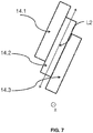
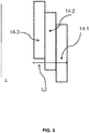
- the figure 9 illustrates an embodiment of the present invention.
- the branch 6 is segmented along a plane perpendicular to the length L2 so as to form a series of perpendicular segments.
- the at least two magnets 14.1, 14.2 each have the shape of one of the perpendicular segments of said series.
- to each of the segments of the series corresponds a single magnet 14.1, 14.2.
- the magnets 14.1, 14.2 are then offset from one another in a direction perpendicular to the length L2 of the branch 6.
- the two magnets 14.1, 14.2 are partly superimposed on their lateral faces.
- the embodiment of the figure 9 differs from that shown on figures 5 and 6 in that the at least two magnets 14.1, 14.2 are offset from one another along the X axis.
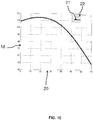
- the figures 10 and 11 each show two curves 21 and 22 of torque of a rotating electric machine. These two curves 21 and 22 are represented in an orthonormal frame comprising an abscissa axis 20 and an ordinate axis 18.
- Axis 20 represents the torque angle, that is to say the angle between the intensity Iphi injected into the stator windings and the component Iq and is expressed in degrees.
- axis 18 represents the value of the torque developed by the machine operating in motor mode and is expressed in Nm
- the curve 21 represents the torque developed by the machine 11 operating in motor mode when it is provided with the rotor 100 according to the state of the art illustrated in particular on figure 4 .
- Curve 22 represents the torque developed by machine 11 operating in motor mode provided with rotor 1 according to the invention.
- the figure 10 represents the torque when the effective value of Iphi is equal to 220 A.
- the figure 11 represents the torque when the rms value of Iphi is 450 A.
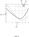
- the figures 12 and 13 each show two ripple curves 25 and 26 of the torque of a rotating electrical machine. These two curves 25 and 26 are represented in an orthonormal frame comprising an abscissa axis 24 and an ordinate axis 23.
- Axis 24 represents the torque angle, that is to say the angle between the intensity Iphi injected into the stator windings and the component Iq and is expressed in degrees.
- axis 23 represents the torque ripple of the machine operating in motor mode and is expressed in Nm
- Curve 25 represents the torque ripple of machine 11 operating in motor mode provided with a rotor 100 according to the state of the art illustrated in particular on the figure 4 .
- Curve 26 represents the torque ripple of machine 11 operating in motor mode provided with rotor 1 according to the invention.
- the figure 12 represents the torque when the effective value of Iphi is equal to 220 A.
- the figure 13 represents the torque when the rms value of Iphi is 450 A.
- the curve 26 is significantly lower than the curve 25 for a torque angle between 0 and 30 ° when the rms value of Iphi is 220 A and between 0 and 40 ° when the rms value of Iphi is 450 A It is deduced from this that for these ranges of angles the torque ripple is greatly reduced.
- the torque ripple is divided by 4 when the torque angle is of the order of 20 ° when the rms value of Iphi is equal to 450 A.
Landscapes
- Engineering & Computer Science (AREA)
- Power Engineering (AREA)
- Permanent Field Magnets Of Synchronous Machinery (AREA)
- Iron Core Of Rotating Electric Machines (AREA)
Description
- La présente invention porte sur un rotor pour une machine électrique tournante et sur une machine électrique tournante comprenant un tel rotor.
- De manière connue, les machines électriques tournantes comportent deux parties coaxiales à savoir un rotor et un stator entourant le corps du rotor (Cf.
US2002/175583 ,EP2264860 ,US2003/127280 ,CN102790458 ,DE102012205191 ) - La
figure 1 montre la structure d'une machine électrique tournante défluxable selon l'état de la technique. La machine 11 est de type à aimants enterrés et à concentration de flux et comprend un stator 10 et un rotor 100. Une réalisation concrète d'une telle machine est par exemple un moteur de traction de 8 à 10 KW pour des applications dans des véhicules automobiles du type dits «mild-hybrid». Une forme de réalisation particulière de ce moteur comprend un stator 10 ayant 60 encoches 101 et un rotor 100 comportant 10 pôles Nord et Sud alternés. Le rotor 100 a un diamètre de l'ordre 100 mm et une longueur axiale de l'ordre de 50 mm. Le rotor 100 comporte 10 aimants permanents PM ayant une forme sensiblement rectangulaire et pour dimensions : longueur (Lm) x hauteur (ha) x largeur (la) 50 mm x 25 mm x 5 mm. - Le stator 10 et le rotor 100 sont réalisés avec des paquets de tôles métalliques formant des masses magnétiques. Les encoches 101 du stator 10 sont prévues pour recevoir des bobinages statoriques (non représentés) et forment entre elles une pluralité de dents statoriques. Les encoches 101 seront ainsi prévues pour loger des bobinages concentrés, bobinés sur des grosses dents, ou bien des bobinages distribués. Le rotor 100 a la forme générale d'un cylindre multilobé, chacun des lobes correspondant à un pôle magnétique du rotor. On définit un entrefer 16 entre le stator 10 et le rotor 100.
- Les aimants PM sont disposés de manière radiale. Les aimants PM sont de préférence des aimants permanents comprenant des terres rares tels que des aimants de type Néodyme-Fer-Bore (NeFeB), Samarium-Fer (SmFe), Samarium-Cobalt (SmCo) ou bien des aimants obtenus à partir de ferrites frittés ou liés. Le corps du rotor 100 est muni d'un axe X et comprend un alésage central débouchant à ses deux extrémités faciales et destiné à recevoir un arbre d'entraînement. On notera que dans la présente invention l'arbre d'entraînement pourra être réalisé dans un matériau magnétique ou amagnétique selon l'application envisagée.
- Le rotor 100 comprend également des évidements E1, E2 et E3 qui se répètent pour chaque pôle et s'étendent axialement sur sensiblement toute la longueur du rotor.
- Des tôles de fermeture, sans les évidements E1, E2 et E3, sont éventuellement prévues aux extrémités faciales du rotor 100 afin de contribuer à l'assemblage du rotor 100. Des points de soudure (non représentés) à la périphérie du paquet de tôles et des tirants traversants (non représentés), parallèles à l'axe central, sont également prévus pour l'assemblage du rotor 100.
- Les tirants traversants sont réalisés dans un matériau magnétique ou amagnétique, selon les applications. Avantageusement, le passage des tirants à travers le paquet de tôles du rotor 100 pourra se faire à travers les évidements E3. Dans cette forme de réalisation particulière, les évidements E1, E2 et E3 sont chacun au nombre de 10, ce nombre correspondant au nombre N=10 de pôles magnétiques du rotor 100.
- Il est connu d'utiliser la machine 11 en mode alternateur ou en mode moteur. En mode moteur, on injecte dans les bobinages statoriques une intensité Iphi qui est la résultante de composantes d'intensité Id et Iq qui sont en quadrature. On définit un angle de couple qui correspond à l'angle entre l'intensité Iphi et la composante Iq.
- La
figure 2 montre un rotor 100 selon l'état de la technique, d'axe X, ayant un corps 3 fixé à un moyeu central (non représenté) cannelé à sa périphérie interne pour fixation en rotation sur un arbre. Le corps 3 comporte des logements 9 destinés à recevoir des aimants permanents 14 maintenus radialement et axialement à l'aide de dispositifs de maintien 17 visibles sur lafigure 3 exerçant par déformation un effort radial sur l'aimant 14 ainsi que sur une partie axiale intérieure 91a du logement 9. - Le rotor 100 est formé par un empilement de tôles s'étendant dans un plan radial perpendiculaire à l'axe X. Le paquet de tôles forme le corps 3 du rotor 100 et est en matière ferromagnétique. Les tôles du corps 3 sont préférentiellement maintenues au moyen de rivets traversant axialement le rotor 100 de part en part via des ouvertures 31.
- Des évidements 5 sont ménagés dans le corps 3. Selon un mode de réalisation préféré, ces évidements 5 présentent, une forme issue de la combinaison d'une forme en triangle et d'une forme en trapèze. Le triangle présente un côté commun avec le grand côté du trapèze. Les évidements 5 permettent de bien canaliser le flux magnétique.
- Les logements 9 du corps 3 sont préférentiellement de forme sensiblement parallélépipédique destinés à recevoir les aimants permanents 14. Ces logements 9 espacés régulièrement sur la circonférence du rotor et situés dans le corps 3 du rotor 100, présentent une direction longitudinale d'extension parallèle à l'axe X et une direction d'extension s'étendant sensiblement radialement par rapport à l'axe X. Les logements 9, formés dans le corps 3, sont ici préférentiellement et de section globalement rectangulaire.
- Le logement 9 suit une section perpendiculaire à l'axe X et peut être traversant. Alternativement, les logements 9 peuvent être fermés l'une de leurs extrémités axiales.
- Les logements 9 sont délimités radialement par la partie axiale intérieure 91a déjà mentionnée et une partie axiale extérieure 91b. Les faces des parties 91b et 91a sont respectivement orientées radialement vers l'axe X du rotor 100 et côté opposé à l'axe X du rotor 100.
- Autrement dit, la partie axiale 91a interne est tournée vers l'extérieur du rotor 100. Tandis que la partie axiale 91b est tournée vers l'intérieur du rotor 100. L'extérieur du rotor 100 est formé par la paroi radiale du rotor 100 est la partie du rotor 100 la plus éloignée de l'axe X et l'intérieur du rotor 100 est la partie du rotor 100 qui est relativement la plus proche du centre du rotor 100 et de l'axe X.
- Les logements 9 sont destinés à recevoir chacun des éléments sous la forme d'un aimant 14. Les aimants 14 peuvent être en terre rare par exemple à base de Samarium-Cobalt (SmCo) ou à base de Néodymium- Fer- Bore (NdFeB) ayant une haute coercivité et un taux élevé de rémanence ainsi qu'une bonne tenue en température. Ils peuvent également être en ferrite.
- En variante on peut loger dans des logements 9 des aimants 14 en terre rare et dans d'autres logements 9 des ferrites, dont le nombre pourra être égal ou inférieur au nombre d'aimants en terre rare. Ainsi on peut utiliser des aimants en terre rare coûteux pour s'approcher au mieux par exemple d'une puissance électrique souhaitée de la machine et compléter cela par des aimants en ferrite moins coûteux. En outre dans certains des logements 9 on peut remplacer au moins l'un des aimants par un élément amagnétique, par exemple en Aluminium, de même forme pour obtenir la puissance désirée de la machine électrique.
- Comme montré sur la
figure 2 , la partie axiale intérieure 91a du logement 9 comprend deux portions concaves 42 et une portion saillante 41 s'étendant axialement suivant l'axe X. La portion saillante 41 est à plus grande proximité de la face 15 de l'aimant que les deux portions concaves 42. Les évidements 5 sont ménagés dans le corps 3 et positionnées entre les logements 9 sur une trajectoire reliant successivement les portions saillantes 41 des logements 9 consécutifs, préférentiellement suivant une section coupant perpendiculairement l'axe X du rotor 100. Les évidements 5 s'étendent suivant une longueur L. Sur lafigure 2 est également représentée une largeur I du logement 9. - Sur la
figure 3 est représenté le corps 3 du rotor 100 comprenant un axe X et muni de deux faces d'extrémités axiales 4a et 4b. Le corps du rotor 3 comprend les logements 9 délimités par les parties 91a et 91b. On peut également voir un dispositif de maintien 17 de l'aimant 14 dont une partie centrale 19 exerce par déformation un effort radial sur l'aimant 14 ainsi que sur une partie axiale intérieure 91a du logement 9. Le dispositif de maintien 17 comprend des rabats 30 et 40 permettant la retenue du dispositif de maintien 17 par contact sur les faces d'extrémités axiales 4b et 4a respectivement. Les aimants 14 ont une bonne tenue à la force centrifuge grâce au dispositif de 17 qui rattrape les jeux dus aux tolérances de fabrication des logements 9 et des aimants 14. - La
figure 4 illustre un rotor 100 selon l'état de la technique. Il est représenté en section selon un plan perpendiculaire à l'axe X. Le rotor 100 comprend un corps de rotor 3 d'axe X. Le corps de rotor 3 comprend des évidements 5.1 et 5.2 et des logements 9. - Chacun des logements 9 est délimité par une partie axiale interne 91a et une partie axiale externe 91b référencées sur la
figure 4 . Chacun des logements 9 accueillent un aimant 14 respectivement. - Les aimants 14 sont ainsi enterrés dans le corps de rotor 3. Le groupe d'aimants de deux logements 9 adjacents forment un V muni de deux branches 6. Le groupe d'aimants du V forme un pôle magnétique 8 du rotor 100.
- Le rotor 100 comprend d'autres pôles magnétiques 8 qui sont alternés sur le pourtour du rotor. Ces pôles sont destinés à interagir avec le stator 10 de ladite machine électrique tournante 11. Par ailleurs, on définit en référence à la
figure 4 ,3 zones du corps de rotor Z1, Z2 et Z3. Selon le rotor 100 de lafigure 5 , il est prévu des aimants 14 de taille : 6x20x44 mm3. - Cette machine donne satisfaction néanmoins il peut être souhaitable d'améliorer encore celle-ci. Tout d'abord, les aimants utilisés comprennent souvent des terres rares et leur coût est très important. De plus, la tenue en centrifugation de ces aimants est exigeante. D'autre part, les fuites en bout d'aimant peuvent être importantes, cela est dû notamment à l'entrefer. Egalement, ces machines peuvent présenter une ondulation de couple. Ces ondulations de couple peuvent affecter le rendement de la machine électrique.
- Il existe donc un besoin pour une machine muni d'un rotor à aimants permanents ayant un coût maitrisé et un rendement amélioré.
- L'invention a pour objet de répondre à ce souhait tout en remédiant à au moins un de ces inconvénients précités.
- Il est proposé un rotor pour machine électrique, le rotor étant défini par la combinaison de caractéristiques de la revendication 1.
- Selon une caractéristique générale de l'invention, chaque branche dudit V comprend au moins deux aimants.
- Il est ainsi possible d'utiliser plusieurs aimants de taille réduite dont le coût cumulé est diminué par rapport à un unique aimant.
- Selon l'invention, les au moins deux aimants se superposent sur une partie de leurs faces latérales et sont décalés selon une direction perpendiculaire à ladite longueur. On réduit ainsi l'ondulation de couple. De plus, du fait du décalage des lignes de champs les niveaux de variation de champs sont réduits, ce qui permet de diminuer les pertes par courant de Foucault dans les aimants. On peut ainsi, pour notamment un même comportement en mode moteur de la machine électrique tournante, réduire la quantité d'aimant, par exemple de 10%.
- Selon un mode de réalisation non couvert par la présente invention, la branche est segmentée selon un plan comprenant sa longueur de sorte à former une série de segments longitudinaux, les au moins deux aimants ont chacun la forme d'un des segments longitudinaux de ladite série.
- Selon un mode de réalisation non couvert par la présente invention, les au moins deux aimants se superposent sur une partie de leurs faces longitudinales et sont décalés entre eux selon la longueur de la branche.
- Selon l'invention, la branche est segmentée selon un plan perpendiculaire à sa longueur de sorte à former une série de segments perpendiculaires, les au moins deux aimants ont chacun la forme d'un des segments perpendiculaires de ladite série. On obtient ainsi des aimants compacts et plus solides
- Selon l'invention, les aimants ont une direction de polarisation perpendiculaire à la longueur de la branche. Ainsi le décalage suivant une direction perpendiculaire à la direction la longueur ne crée pas d'entrefer. Ce qui permet de limiter les pertes de flux. Par exemple, la direction de polarisation se situe dans le plan perpendiculaire à l'axe X.
- Selon d'autres caractéristiques prise isolément ou en combinaison :
- les au moins deux aimants se superposent sur une partie de leurs faces latérales et sont décalés entre eux selon une direction perpendiculaire à la longueur de la branche et située dans un plan perpendiculaire à l'axe X. Il s'agit d'un mode de réalisation facile à mettre en œuvre en adaptant la forme des logements. Du fait du fractionnement des aimants, on peut répartir les efforts centrifuges sur l'ensemble des parois du logement et éviter un point de rupture situé par exemple sur la paroi du logement la plus proche de l'entrefer. Cela permet notamment de réduire la bande de matière entre la paroi axiale externe du logement et l'entrefer, ce qui réduit les pertes de flux.
- pour chaque branche l'aimant radialement extérieur est décalé vers l'extérieur du V. Ainsi, du fait de ce décalage, on peut rapprocher l'aimant du stator et de l'entrefer pour réduire les pertes de flux.
- les aimants d'une branche sont de même taille. Le procédé d'industrialisation est simplifié.
- le rotor comprend pour chacun de ses pôles magnétiques deux évidements, le corps de rotor comprenant un pont défini entre les deux évidements et reliant ledit pôle à une partie annulaire du corps du rotor entourant l'axe X. Cela permet une saturation du pont ce qui permet de limiter le passage de flux vers l'axe. En effet, ce flux est perdu pour le fonctionnement de la machine et en le limitant on diminue les pertes de flux. Plus généralement ces évidements permettent de réduire le poids du corps de rotor afin de diminuer l'inertie de la machine électrique tournante.
- les deux branches du V forment un angle inférieur à 90°.
- les au moins deux aimants d'une branche ont des caractéristiques magnétiques différentes. Il est possible de prévoir que seul l'aimant radialement extérieur ou proche de l'entrefer a une composition qui lui permet de résister hautement à la démagnétisation. Ainsi, on obtient une résistance globale à la démagnétisation de l'ensemble du rotor satisfaisante sans utiliser des composants terre rare chère pour l'ensemble des aimants permanents. Dans ce cas, on peut par exemple prévoir que l'aimant radialement extérieur est à base de Samarium-Cobalt (SmCo) ou de Néodymium- Fer- Bore (NdFeB) pour avoir une haute coercivité et que les autres aimants sont des aimants ferrites ou Alnico.
- L'invention a également pour objet une machine électrique tournante qui comprend un rotor tel que décrit ci dessus comprenant entre 8 et 12 paires de pôles et un stator comprenant entre 26 et 34 encoches entourant ledit rotor. Il s'agit alors d'une machine électrique tournante optimisée qui permet un bon rendement.
- L'invention sera mieux comprise à la lecture de la description qui suit et à l'examen des figures qui l'accompagnent. Ces figures ne sont données qu'à titre illustratif mais nullement limitatif de l'invention.
- La
figure 1 montre, de manière simplifiée, la structure d'une machine électrique tournante à aimants permanents selon l'état de la technique ; - la
figure 2 montre une vue de dessus d'un exemple de réalisation d'un rotor à aimants permanents à concentration de flux selon l'état de la technique ; - la
figure 3 montre une vue en perspective de l'exemple de réalisation du rotor représenté sur la figure précédente ; - la
figure 4 montre un autre rotor selon l'état de la technique ; - les
figures 5 et6 montrent un rotor selon un mode de réalisation non couvert par l'invention ; - les
figures 7 et8 montrent des dispositions des aimants pour le rotor selon d'autre modes de réalisation non couverts par l'invention ; - la
figure 9 montre une disposition d'aimants pour le rotor selon la présente invention et - les
figures 10 et11 montrent le couple de la machine comprenant un rotor selon un mode de réalisation de l'invention ; et - les
figures 12 et13 montrent l'ondulation de couple de la machine comprenant un rotor selon un mode de réalisation de l'invention. - Les éléments identiques, similaires, ou analogues conservent la même référence d'une figure à l'autre.
- Les
figures 5 et6 illustrent un rotor 1. - Selon un mode de réalisation d'une machine électrique tournante 11, ce rotor 1 est représenté en section selon un plan perpendiculaire à l'axe X. Il est par exemple apte à fonctionner avec le stator 10 de la
figure 1 , en lieu et place du rotor 100 illustré sur lafigure 1 . Selon un autre mode un mode de réalisation d'une machine électrique tournante 11, on peut prévoir que le rotor 1 fonctionne avec un stator comprenant entre 26 et 34 encoches, par exemple 30 encoches. - Le rotor 1 comprend un corps de rotor 3 d'axe X. Le corps de rotor 3 comprend des évidements 5.1 et 5.2 et des logements 9.
- Chacun des logements 9 est délimité par une partie axiale interne 91a et une partie axiale externe 91b référencées sur la
figure 6 . Chacun des logements 9 accueillent des aimants 14.1, 14.2. Selon le mode de réalisation illustré sur lesfigures 5 et6 , il est prévu pour chacun des logements deux aimants 14.1 et 14.2. On pourrait bien entendu prévoir un plus grand nombre d'aimants. Par exemple, les aimants 14.1, 14.2 d'une branche 6 sont de même taille. On peut également prévoir que tous les aimants du rotor 1 sont de même taille. - Les aimants 14.1 et 14.2 sont ainsi enterrés dans le corps de rotor 3. Le groupe d'aimants 14.1, 14.2 de deux logements 9 adjacents forment un V muni de deux branches 6 dont une est référencée sur la
figure 6 . Le V délimite une partie interne 13 entre les deux branches du V et une partie externe 15 complémentaire. Par exemple les deux branches du V contenant la partie interne 13 forment un angle inférieure à 90°, par exemple 56°. Par exemple, les branches du V sont désaxés par rapport au rayon du rotor 1. - Le groupe d'aimants 14.1, 14.2 du V forme un pôle magnétique 8 du rotor 1. Le rotor 1 comprend d'autres pôles magnétiques 8 qui sont alternés sur le pourtour du rotor. Ces pôles sont destinés à interagir avec le stator 10 de ladite machine électrique tournante 11. Selon un mode de réalisation, le rotor comprend entre 8 et 12 paires de pôles. Selon un exemple de ce mode de réalisation, le rotor comprend 10 paires de pôles.
- En d'autres termes, sur la
figure 5 est notamment représenté un pôle magnétique 8 comprenant 4 aimants 14.1, 14.2 enterrés dans le corps de rotor 3, ces 4 aimants formant un V. Par exemple, on peut prévoir que tous les aimants 14.1-14.2 du pôle magnétique 8 sont de même taille. - Comme on peut le voir sur la
figure 5 , le corps du rotor comprend en outre une partie annulaire 2 entourant l'axe X. Pour chaque pôle, les deux évidements 5.1, 5.2 du corps de rotor définissent alors un pont 7 qui relie ledit pôle 8 à ladite partie annulaire 2. - On peut prévoir que pour chaque branche, les deux aimants 14.1, 14.2 sont décalés selon une longueur L2 de la branche 6 ou une direction perpendiculaire à ladite longueur L2. La longueur L2 d'une branche 6 est définie comme la distance entre les deux faces les plus éloignées des aimants selon un plan perpendiculaire à l'axe X et s'étend par exemple selon la direction des faces longitudinales du logement 9 accueillant les aimants de la branche. Toutefois, la longueur L2 est dans un plan perpendiculaire à l'axe X.
- Par exemple, la forme du logement 9 comprend au moins deux parallélépipède rectangle qui sont parallèles entre eux. Dans ce cas, lesdites faces longitudinales sont celles qui sont alignées avec une direction d'extension préférentielle du parallélépipède rectangle formant le logement 9. Ainsi, les parois des au moins deux parallélépipèdes rectangles sont parallèles.
- Par exemple, pour chaque branche, chaque aimant 14.1, 14.2 de la pluralité d'aimants de chaque branche 6 présente une forme de parallélépipède rectangle ayant des faces longitudinales alignées avec les faces longitudinales du logement 9 et des faces latérales perpendiculaires à la direction L2 tout en comprenant l'axe X.
- Comme illustré sur les
figures 5 et6 , la branche 6 est segmentée selon un plan perpendiculaire à la longueur L2 de sorte à former une série de segments perpendiculaires. Les au moins deux aimants 14.1, 14.2 ont alors chacun la forme d'un des segments perpendiculaires de ladite série. Par exemple à chacun des segments de la série correspond un unique aimant 14.1, 14.2. - Dans ce cas, comme illustré sur les
figures 5 et6 , on peut prévoir que les aimants de chaque branche, sont superposés les uns sur les autres suivant une partie de leurs faces latérales pour obtenir une puissance maximale de la machine. Les aimants 14.1, 14.2 ainsi empilés forment alors un empilement d'éléments magnétiques ayant par exemple, une forme complémentaire de celle des logements 9. - Comme illustré sur les
figures 5 et6 , on peut prévoir que les au moins deux aimants 14.1, 14.2 sont décalés entre eux selon une direction perpendiculaire à la longueur L2 de la branche 6, ladite direction de décalage étant de plus située dans un plan perpendiculaire à l'axe X. - Dans ce cas, bien que les aimants puissent présenter des faces latérales de même taille, pour un aimant donné sa face latérale ne recouvre pas totalement la face de l'aimant sur lequel il est empilé. En effet, les aimants sont décalés, si bien que la face latérale de l'aimant est également décalée par rapport à la face de l'aimant sur lequel il est empilé.
- Comme illustré sur les
figures 5 et6 , on peut prévoir que pour chaque branche 6 l'aimant 14.1 radialement extérieur, c'est à dire l'aimant le plus proche de la partie axiale externe 91 b par rapport à l'axe X, est décalé vers la partie externe 15 du V. En d'autres termes, l'aimant 14.1 radialement extérieur est décalé vers l'extérieur du V. - On peut prévoir que les aimants 14.1, 14.2 du pôle magnétique ont une direction de polarisation 12 perpendiculaire à la longueur de la branche L2. Par exemple, cette direction de polarisation 12 est située dans un plan perpendiculaire à l'axe X.
- On peut également prévoir que le dispositif de maintien 17 de l'état de la technique illustré sur la
figure 3 est utilisé pour le maintien des aimants, un dispositif de maintien étant utilisé pour chaque branche. - La
figure 6 illustre en outre une bande de matière 27 du corps de rotor 3 située entre la paroi axiale externe 91b et l'entrefer 16. Dans le rotor 1, il est possible de réduire cette bande de matière 27 nécessaire pour le maintien des aimants en centrifugation tout en conservant la même vitesse de rotation maximale du rotor 1. En effet, la bande de matière 27 ne va supporter que l'aimant 14.1 (qui ne représente qu'un demi aimant par rapport à l'aimant 14 du rotor 100 de lafigure 4 ) et les aimants 14.1 et 14.2 sont également supportés par le fer notamment le coin 28 de l'aimant 14.2 et le coin 29 de l'aimant 14.2. - D'autre part, comme on peut le voir sur la
figure 6 , en déplaçant l'aimant 14.1 vers l'extérieur du V, la distance entre un coin 28 de l'aimant 14.1 et l'entrefer 16 augmente. On peut alors éloigner l'aimant 14.1 de l'axe X et le rapprocher de l'entrefer tout en conservant une bande de matière 27 permettant la tenue en centrifugation. - Ainsi, en rapprochant l'aimant et/ou réduisant la bande de matière on limite les pertes de flux.
- On définit également en référence à la
figure 6 , les zones Z1, Z2 et Z3. On peut ainsi comparer les résultantes des contraintes mécaniques sur ces trois zones pour le rotor de l'état de la technique illustré à lafigure 4 et celui illustré sur lafigure 6 . - Ainsi, pour une vitesse de rotation du rotor de l'état de la technique illustré en
figure 4 égale à 8400 tr/min, on obtient des contraintes mécaniques de 205, 220 et 315 MPa au niveau Z1, Z2 et Z3 respectivement. - Tandis que pour une vitesse de rotation du rotor illustré à la
figure 6 égale à 8400 tr/min, on obtient des contraintes mécaniques de 205, 215 et 325 MPa au niveau Z1, Z2 et Z3 respectivement. - On obtient des contraintes mécaniques sur ces trois zones qui sont globalement similaires à celle du rotor de l'état de la technique. C'est avantageux car la bande de matière 27 du rotor de l'état de la technique est d'une épaisseur globalement réduite.
- Selon le rotor 1 de la
figure 6 , il est prévu par exemple, des aimants 14.1 et 14.2 de taille: 6x9x44 mm3 qui ont une induction rémanente Br comprise entre 1.2 et 1.3 Tesla. On constate ainsi que la quantité d'aimant est réduite par rapport à un unique aimant de 6x10x44 mm3 du rotor 100 illustré sur lafigure 4 . - Plus généralement, on peut prévoir un rotor 1 de la
figure 6 présentant les caractéristiques suivantes : - hauteur d'aimant (selon l'axe X) : 44mm ;
- longueur d'aimant (selon la longueur L2) : 9 mm, la longueur L2 représentant deux fois la longueur d'aimant quand il y a deux aimants par logement ;
- largeur d'aimant dans le plan perpendiculaire à l'axe X et selon une direction perpendiculaire à la longueur L2 : 6mm ;
- Ratio largeur aimant / longueur aimant : 0.6667 ;
- Selon le mode de réalisation d'une machine électrique tournante 11 dans lequel le rotor 1 fonctionne avec un stator comprenant entre 26 et 34 encoches, par exemple 30 encoches, on peut prévoir les caractéristiques suivantes pour la machine électrique :
- Ratio entre le diamètre intérieur et le diamètre extérieur du stator : 0.7176 ;
- Ratio entre largeur de dent stator (selon une direction ortho radiale, dans un plan perpendiculaire à l'axe X) et hauteur de dent stator (selon le rayon du stator) : 0.3252 ;
- Ratio entre le diamètre extérieur du stator et le diamètre extérieur du rotor : 0.7144 ;
- Ratio entre le diamètre de l'arbre et le diamètre extérieur du rotor : 0.6333 ;
- Facteur de concentration de flux : 0.6452.
- Les
figures 7 et8 illustrent un autre mode de réalisation non couvert par l'invention, selon lequel il est prévu que la branche 6 est segmentée selon un plan comprenant la longueur L2 de sorte à former une série de segments longitudinaux, les au moins deux aimants 14.1, 14.2 ont chacun la forme d'un des segments longitudinaux de ladite série. Par exemple à chacun des segments de la série correspond un unique aimant 14.1, 14.2. Les au moins deux aimants 14.1, 14.2 sont alors décalés entre eux selon la longueur L2 de la branche 6 et se superposent sur une partie de leurs faces longitudinales. - Plus précisément, dans la
figure 7 , les segments longitudinaux sont formés à partir de la segmentation de la branche 6 selon un plan comprenant la longueur L2 et l'axe X. - Tandis que dans la
figure 8 , les segments longitudinaux sont formés à partir de la segmentation de la branche 6 selon un plan perpendiculaire à l'axe X et comprenant la longueur L2. - La
figure 9 illustre un mode de réalisation de la présente invention. Tout comme lesfigures 5 et6 , la branche 6 est segmentée selon un plan perpendiculaire à la longueur L2 de sorte à former une série de segments perpendiculaires. Les au moins deux aimants 14.1, 14.2 ont chacun la forme d'un des segments perpendiculaires de ladite série. Par exemple à chacun des segments de la série correspond un unique aimant 14.1, 14.2. Les aimants 14.1, 14.2 sont alors décalés entre eux selon une direction perpendiculaire à la longueur L2 de la branche 6. Ainsi, les deux aimants 14.1, 14.2 se superposent en partie sur leurs faces latérales. Toutefois, le mode de réalisation de lafigure 9 se distingue de celui illustré sur lesfigures 5 et6 par le fait que les au moins deux aimants 14.1, 14.2 sont décalés entre eux selon l'axe X. - Les
figures 10 et11 montrent chacune deux courbes 21 et 22 de couple d'une machine électrique tournante. Ces deux courbes 21 et 22 sont représentées dans un repère orthonormé comprenant un axe des abscisses 20 et un axe des ordonnées 18. L'axe 20 représente l'angle de couple c'est à dire l'angle entre l'intensité Iphi injectée dans les bobinages statoriques et la composante Iq et est exprimé en degré. Tandis que l'axe 18 représente la valeur du couple développé par la machine fonctionnant en mode moteur et est exprimé en N.m. - La courbe 21 représente le couple développé par la machine 11 fonctionnant en mode moteur lorsqu'elle est munie du rotor 100 selon l'état de la technique illustré notamment sur la
figure 4 . La courbe 22 représente le couple développé par la machine 11 fonctionnant en mode moteur munie du rotor 1 selon l'invention. Lafigure 10 représente le couple lorsque la valeur efficace de Iphi vaut 220 A. Lafigure 11 représente le couple lorsque la valeur efficace de Iphi vaut 450 A. - On constate que les courbes 21 et 22 sont quasiment superposées tant pour la valeur Iphi efficace de 450 A ou 220 A. On en déduit que les valeurs de couple développé par la machine fonctionnant en mode moteur muni d'un rotor selon l'état de la technique ou d'un rotor selon l'invention sont sensiblement égales.
- Les
figures 12 et13 montrent chacune deux courbes 25 et 26 d'ondulation du couple d'une machine électrique tournante. Ces deux courbes 25 et 26 sont représentées dans un repère orthonormé comprenant un axe des abscisses 24 et un axe des ordonnées 23. L'axe 24 représente l'angle de couple c'est à dire l'angle entre l'intensité Iphi injectée dans les bobinages statoriques et la composante Iq et est exprimé en degré. Tandis que l'axe 23 représente l'ondulation de couple de la machine fonctionnant en mode moteur et est exprimé en N.m. La courbe 25 représente l'ondulation de couple de la machine 11 fonctionnant en mode moteur muni d'un rotor 100 selon l'état de la technique illustré notamment sur lafigure 4 . La courbe 26 représente l'ondulation de couple de la machine 11 fonctionnant en mode moteur muni du rotor 1 selon l'invention. Lafigure 12 représente le couple lorsque la valeur efficace de Iphi vaut 220 A. Lafigure 13 représente le couple lorsque la valeur efficace de Iphi vaut 450 A. - On constate que la courbe 26 est sensiblement plus basse que la courber 25 pour un angle de couple compris entre 0 et 30° lorsque la valeur efficace de Iphi vaut 220 A et compris entre 0 et 40° lorsque la valeur efficace de Iphi vaut 450 A. On en déduit que pour ces gammes d'angles l'ondulation de couple est fortement réduite. Notamment, l'ondulation de couple est divisée par 4 lorsque l'angle de couple est de l'ordre de 20° lorsque la valeur efficace de Iphi vaut 450 A.
Claims (8)
- Rotor (1) pour machine électrique tournante (11), ledit rotor comprenant :- un corps de rotor (3) muni d'un axe X ;- des pôles magnétiques (8) destinés à interagir avec un stator (10) de ladite machine électrique tournante, chaque pôle magnétique (8) comprenant des aimants (14.1, 14.2),lesdits aimants (14.1, 14.2) étant enterrés dans ledit corps de rotor (3) de telle sorte qu'ils forment en section selon un plan perpendiculaire à l'axe X un V pour chaque pôle (8) du rotor ;
chaque branche (6) dudit V comprenant au moins deux aimants (14.1, 14.2) et ayant une longueur (L2) dans un plan perpendiculaire à l'axe X,
lesdits aimants (14.1, 14.2) ayant une direction de polarisation (12) perpendiculaire à la longueur de la branche (L2),
la branche (6) étant segmentée selon un plan perpendiculaire à sa longueur (L2) de sorte à former une série de segments perpendiculaires, les au moins deux aimants (14.1, 14.2) rayant chacun la forme d'un des segments perpendiculaires de ladite série,
caractérisé en ce que les au moins deux aimants (14.1, 14.2) sont décalés entre eux selon une direction perpendiculaire à la longueur (L2) de la branche (6) de sorte que lesdits aimants se superposent sur une partie de leurs faces latérales, les faces latérales étant perpendiculaires à la longueur (L2) de la branche et comprenant l'axe X, et
les au moins deux aimants (14.1, 14.2) sont décalés entre eux selon l'axe X. - Rotor selon la revendication 1, caractérisé en ce que les au moins deux aimants (14.1, 14.2) se superposent sur une partie de leurs faces latérales et sont décalés entre eux selon une direction perpendiculaire à la longueur (L2) de la branche (6) et située dans un plan perpendiculaire à l'axe X.
- Rotor selon la revendication 1 ou 2, caractérisé en ce que pour chaque branche (6) l'aimant (14.1) radialement extérieur est décalé vers l'extérieur du V.
- Rotor selon l'une quelconque des revendications précédentes, caractérisé en ce que les aimants (14.1, 14.2) d'une branche (6) sont de même taille.
- Rotor selon l'une quelconque des revendications précédentes, caractérisé en ce que le rotor comprend pour chacun de ses pôles magnétiques (8) deux évidements (5.1, 5.2), le corps (3) de rotor comprenant un pont (7) défini entre les deux évidements et reliant ledit pôle (8) à une partie annulaire (8) du corps (3) du rotor entourant l'axe X.
- Rotor selon l'une quelconque des revendications précédentes, caractérisé en ce que les deux branches du V forment un angle inférieur à 90°.
- Rotor selon l'une quelconque des revendications précédentes, caractérisé en ce que les au moins deux aimants (14.1 , 14.2) d'une branche (6) ont des caractéristiques magnétiques différentes.
- Machine électrique tournante (11) caractérisé en ce qu'elle comprend un rotor (1) selon l'une des revendications précédentes comprenant entre 8 et 12 paires de pôles et un stator (10) comprenant entre 26 et 34 encoches entourant ledit rotor (1).
Applications Claiming Priority (1)
| Application Number | Priority Date | Filing Date | Title |
|---|---|---|---|
| FR1652911A FR3049782B1 (fr) | 2016-04-04 | 2016-04-04 | Rotor pour machine electrique tournante |
Publications (2)
| Publication Number | Publication Date |
|---|---|
| EP3229348A1 EP3229348A1 (fr) | 2017-10-11 |
| EP3229348B1 true EP3229348B1 (fr) | 2020-10-21 |
Family
ID=56611332
Family Applications (1)
| Application Number | Title | Priority Date | Filing Date |
|---|---|---|---|
| EP17164677.1A Active EP3229348B1 (fr) | 2016-04-04 | 2017-04-04 | Rotor pour machine électrique tournante |
Country Status (2)
| Country | Link |
|---|---|
| EP (1) | EP3229348B1 (fr) |
| FR (1) | FR3049782B1 (fr) |
Families Citing this family (2)
| Publication number | Priority date | Publication date | Assignee | Title |
|---|---|---|---|---|
| CN108448767A (zh) * | 2018-05-11 | 2018-08-24 | 哈尔滨理工大学 | 一种具有新型转子结构的永磁同步电动机 |
| DE102018210967A1 (de) * | 2018-07-04 | 2020-01-09 | Brose Fahrzeugteile GmbH & Co. Kommanditgesellschaft, Würzburg | Rotor |
Family Cites Families (9)
| Publication number | Priority date | Publication date | Assignee | Title |
|---|---|---|---|---|
| JP2002354729A (ja) * | 2001-05-25 | 2002-12-06 | Hitachi Ltd | 永久磁石式回転電機およびそれを用いた空気調和機 |
| ES2654612T3 (es) * | 2009-06-18 | 2018-02-14 | Bombardier Transportation Gmbh | Rotor para máquina eléctrica de un vehículo sobre carriles, una tal máquina y un vehículo sobre carriles que posee tal máquina |
| CN103038981A (zh) * | 2010-07-30 | 2013-04-10 | 株式会社日立制作所 | 旋转电机和使用它的电动车辆 |
| CN102790458A (zh) * | 2012-03-05 | 2012-11-21 | 珠海格力节能环保制冷技术研究中心有限公司 | 永磁辅助同步磁阻电机转子及其制造方法和电机 |
| DE102012205191A1 (de) * | 2012-03-30 | 2013-10-02 | Bayerische Motoren Werke Aktiengesellschaft | Vibrationsverhinderung bei Synchronmaschinen |
| JP5974599B2 (ja) * | 2012-04-12 | 2016-08-23 | 株式会社デンソー | 回転電機 |
| US8928197B2 (en) * | 2012-04-17 | 2015-01-06 | GM Global Technology Operations LLC | Pole-to-pole asymmetry in interior permanent magnet machines with arc-shaped slots |
| US8664823B2 (en) * | 2012-05-30 | 2014-03-04 | GM Global Technology Operations LLC | Magnetic barrier for minimizing demagnetization in bi-permanent magnet synchronous machines |
| US20140265702A1 (en) * | 2013-03-14 | 2014-09-18 | Remy Technologies Llc | Electric Machine with Skewed Permanent Magnet Arrangement |
-
2016
- 2016-04-04 FR FR1652911A patent/FR3049782B1/fr active Active
-
2017
- 2017-04-04 EP EP17164677.1A patent/EP3229348B1/fr active Active
Non-Patent Citations (1)
| Title |
|---|
| None * |
Also Published As
| Publication number | Publication date |
|---|---|
| FR3049782B1 (fr) | 2021-01-22 |
| EP3229348A1 (fr) | 2017-10-11 |
| FR3049782A1 (fr) | 2017-10-06 |
Similar Documents
| Publication | Publication Date | Title |
|---|---|---|
| EP2372873B1 (fr) | Machine électrique tournante synchrone à aimants permanents et concentration de flux | |
| EP2372872A2 (fr) | Machine électrique tournante synchrone à aimants permanents et concentration de flux | |
| EP3130059A2 (fr) | Rotor de machine électrique tournante | |
| WO2014020273A1 (fr) | Moteur electrique optimise a dents etroites | |
| FR2982093A1 (fr) | Rotor de machine electrique tournante et machine electrique tournante comprenant un rotor | |
| EP3586426A1 (fr) | Machine electrique tournante a flux axial | |
| WO2014072618A1 (fr) | Moteur electrique synchrone a aimants permanents et compresseur electrique comportant un tel moteur electrique | |
| EP2209193A1 (fr) | Machine électrique tournante à pôles saillants | |
| EP3152816B1 (fr) | Rotor a aimants permanents a concentration de flux pour machine electrique tournante | |
| EP2622715A1 (fr) | Machine electrique tournante synchrone avec rotor a double excitation | |
| EP3685492B1 (fr) | Isthmes de ponts magnetiques d'un rotor de machine electrique | |
| EP3229348A1 (fr) | Rotor pour machine électrique tournante | |
| FR3123519A1 (fr) | Machine electrique tournante à configuration co-axiale | |
| EP2372874B1 (fr) | Machine électrique tournante synchrone à aimants permanents et concentration de flux | |
| EP2433349A1 (fr) | Machine vernier a aimants insérés | |
| WO2016146908A1 (fr) | Rotor de machine electrique tournante a aimants permanents | |
| FR3040834A1 (fr) | Corps de rotor a aimants permanents et machine electrique tournante comportant un tel corps | |
| EP2781007A2 (fr) | Rotor a aimants permanents pour une machine electrique tournante | |
| WO2016146909A1 (fr) | Rotor de machine electrique tournante a configuration d'aimants permanents optimisee | |
| FR3167492A1 (fr) | Stator de machine électrique à flux axial par insertion radiale des dents | |
| WO2026017765A1 (fr) | Rotor pour moteur électrique équipé de flasques d'extrémité intégrant des plasto-aimants | |
| FR3098040A1 (fr) | Machine electrique tournante à refroidissement par eau | |
| FR3078594A1 (fr) | Moteur electromagnetique compact polyentrefers et a flux magnetique axial | |
| EP3586425A1 (fr) | Machine electrique tournante avec un stator a encoches obturees et plus particulierement machine electrique synchro reluctante assistee par des aimants permanents | |
| WO2003098784A1 (fr) | Ralentisseur electromagnetique d'un vehicule |
Legal Events
| Date | Code | Title | Description |
|---|---|---|---|
| PUAI | Public reference made under article 153(3) epc to a published international application that has entered the european phase |
Free format text: ORIGINAL CODE: 0009012 |
|
| STAA | Information on the status of an ep patent application or granted ep patent |
Free format text: STATUS: REQUEST FOR EXAMINATION WAS MADE |
|
| 17P | Request for examination filed |
Effective date: 20170404 |
|
| AK | Designated contracting states |
Kind code of ref document: A1 Designated state(s): AL AT BE BG CH CY CZ DE DK EE ES FI FR GB GR HR HU IE IS IT LI LT LU LV MC MK MT NL NO PL PT RO RS SE SI SK SM TR |
|
| AX | Request for extension of the european patent |
Extension state: BA ME |
|
| STAA | Information on the status of an ep patent application or granted ep patent |
Free format text: STATUS: EXAMINATION IS IN PROGRESS |
|
| 17Q | First examination report despatched |
Effective date: 20180420 |
|
| GRAP | Despatch of communication of intention to grant a patent |
Free format text: ORIGINAL CODE: EPIDOSNIGR1 |
|
| STAA | Information on the status of an ep patent application or granted ep patent |
Free format text: STATUS: GRANT OF PATENT IS INTENDED |
|
| INTG | Intention to grant announced |
Effective date: 20200513 |
|
| GRAS | Grant fee paid |
Free format text: ORIGINAL CODE: EPIDOSNIGR3 |
|
| GRAA | (expected) grant |
Free format text: ORIGINAL CODE: 0009210 |
|
| STAA | Information on the status of an ep patent application or granted ep patent |
Free format text: STATUS: THE PATENT HAS BEEN GRANTED |
|
| AK | Designated contracting states |
Kind code of ref document: B1 Designated state(s): AL AT BE BG CH CY CZ DE DK EE ES FI FR GB GR HR HU IE IS IT LI LT LU LV MC MK MT NL NO PL PT RO RS SE SI SK SM TR |
|
| REG | Reference to a national code |
Ref country code: GB Ref legal event code: FG4D Free format text: NOT ENGLISH |
|
| REG | Reference to a national code |
Ref country code: CH Ref legal event code: EP |
|
| REG | Reference to a national code |
Ref country code: DE Ref legal event code: R096 Ref document number: 602017025712 Country of ref document: DE |
|
| REG | Reference to a national code |
Ref country code: IE Ref legal event code: FG4D Free format text: LANGUAGE OF EP DOCUMENT: FRENCH |
|
| REG | Reference to a national code |
Ref country code: AT Ref legal event code: REF Ref document number: 1326841 Country of ref document: AT Kind code of ref document: T Effective date: 20201115 |
|
| REG | Reference to a national code |
Ref country code: AT Ref legal event code: MK05 Ref document number: 1326841 Country of ref document: AT Kind code of ref document: T Effective date: 20201021 |
|
| REG | Reference to a national code |
Ref country code: NL Ref legal event code: MP Effective date: 20201021 |
|
| PG25 | Lapsed in a contracting state [announced via postgrant information from national office to epo] |
Ref country code: NL Free format text: LAPSE BECAUSE OF FAILURE TO SUBMIT A TRANSLATION OF THE DESCRIPTION OR TO PAY THE FEE WITHIN THE PRESCRIBED TIME-LIMIT Effective date: 20201021 Ref country code: NO Free format text: LAPSE BECAUSE OF FAILURE TO SUBMIT A TRANSLATION OF THE DESCRIPTION OR TO PAY THE FEE WITHIN THE PRESCRIBED TIME-LIMIT Effective date: 20210121 Ref country code: RS Free format text: LAPSE BECAUSE OF FAILURE TO SUBMIT A TRANSLATION OF THE DESCRIPTION OR TO PAY THE FEE WITHIN THE PRESCRIBED TIME-LIMIT Effective date: 20201021 Ref country code: PT Free format text: LAPSE BECAUSE OF FAILURE TO SUBMIT A TRANSLATION OF THE DESCRIPTION OR TO PAY THE FEE WITHIN THE PRESCRIBED TIME-LIMIT Effective date: 20210222 Ref country code: FI Free format text: LAPSE BECAUSE OF FAILURE TO SUBMIT A TRANSLATION OF THE DESCRIPTION OR TO PAY THE FEE WITHIN THE PRESCRIBED TIME-LIMIT Effective date: 20201021 Ref country code: GR Free format text: LAPSE BECAUSE OF FAILURE TO SUBMIT A TRANSLATION OF THE DESCRIPTION OR TO PAY THE FEE WITHIN THE PRESCRIBED TIME-LIMIT Effective date: 20210122 |
|
| REG | Reference to a national code |
Ref country code: LT Ref legal event code: MG4D |
|
| PG25 | Lapsed in a contracting state [announced via postgrant information from national office to epo] |
Ref country code: BG Free format text: LAPSE BECAUSE OF FAILURE TO SUBMIT A TRANSLATION OF THE DESCRIPTION OR TO PAY THE FEE WITHIN THE PRESCRIBED TIME-LIMIT Effective date: 20210121 Ref country code: PL Free format text: LAPSE BECAUSE OF FAILURE TO SUBMIT A TRANSLATION OF THE DESCRIPTION OR TO PAY THE FEE WITHIN THE PRESCRIBED TIME-LIMIT Effective date: 20201021 Ref country code: LV Free format text: LAPSE BECAUSE OF FAILURE TO SUBMIT A TRANSLATION OF THE DESCRIPTION OR TO PAY THE FEE WITHIN THE PRESCRIBED TIME-LIMIT Effective date: 20201021 Ref country code: IS Free format text: LAPSE BECAUSE OF FAILURE TO SUBMIT A TRANSLATION OF THE DESCRIPTION OR TO PAY THE FEE WITHIN THE PRESCRIBED TIME-LIMIT Effective date: 20210221 Ref country code: AT Free format text: LAPSE BECAUSE OF FAILURE TO SUBMIT A TRANSLATION OF THE DESCRIPTION OR TO PAY THE FEE WITHIN THE PRESCRIBED TIME-LIMIT Effective date: 20201021 Ref country code: ES Free format text: LAPSE BECAUSE OF FAILURE TO SUBMIT A TRANSLATION OF THE DESCRIPTION OR TO PAY THE FEE WITHIN THE PRESCRIBED TIME-LIMIT Effective date: 20201021 Ref country code: SE Free format text: LAPSE BECAUSE OF FAILURE TO SUBMIT A TRANSLATION OF THE DESCRIPTION OR TO PAY THE FEE WITHIN THE PRESCRIBED TIME-LIMIT Effective date: 20201021 |
|
| PG25 | Lapsed in a contracting state [announced via postgrant information from national office to epo] |
Ref country code: HR Free format text: LAPSE BECAUSE OF FAILURE TO SUBMIT A TRANSLATION OF THE DESCRIPTION OR TO PAY THE FEE WITHIN THE PRESCRIBED TIME-LIMIT Effective date: 20201021 |
|
| REG | Reference to a national code |
Ref country code: DE Ref legal event code: R097 Ref document number: 602017025712 Country of ref document: DE |
|
| PG25 | Lapsed in a contracting state [announced via postgrant information from national office to epo] |
Ref country code: SK Free format text: LAPSE BECAUSE OF FAILURE TO SUBMIT A TRANSLATION OF THE DESCRIPTION OR TO PAY THE FEE WITHIN THE PRESCRIBED TIME-LIMIT Effective date: 20201021 Ref country code: RO Free format text: LAPSE BECAUSE OF FAILURE TO SUBMIT A TRANSLATION OF THE DESCRIPTION OR TO PAY THE FEE WITHIN THE PRESCRIBED TIME-LIMIT Effective date: 20201021 Ref country code: SM Free format text: LAPSE BECAUSE OF FAILURE TO SUBMIT A TRANSLATION OF THE DESCRIPTION OR TO PAY THE FEE WITHIN THE PRESCRIBED TIME-LIMIT Effective date: 20201021 Ref country code: LT Free format text: LAPSE BECAUSE OF FAILURE TO SUBMIT A TRANSLATION OF THE DESCRIPTION OR TO PAY THE FEE WITHIN THE PRESCRIBED TIME-LIMIT Effective date: 20201021 Ref country code: CZ Free format text: LAPSE BECAUSE OF FAILURE TO SUBMIT A TRANSLATION OF THE DESCRIPTION OR TO PAY THE FEE WITHIN THE PRESCRIBED TIME-LIMIT Effective date: 20201021 Ref country code: EE Free format text: LAPSE BECAUSE OF FAILURE TO SUBMIT A TRANSLATION OF THE DESCRIPTION OR TO PAY THE FEE WITHIN THE PRESCRIBED TIME-LIMIT Effective date: 20201021 |
|
| PLBE | No opposition filed within time limit |
Free format text: ORIGINAL CODE: 0009261 |
|
| STAA | Information on the status of an ep patent application or granted ep patent |
Free format text: STATUS: NO OPPOSITION FILED WITHIN TIME LIMIT |
|
| PG25 | Lapsed in a contracting state [announced via postgrant information from national office to epo] |
Ref country code: DK Free format text: LAPSE BECAUSE OF FAILURE TO SUBMIT A TRANSLATION OF THE DESCRIPTION OR TO PAY THE FEE WITHIN THE PRESCRIBED TIME-LIMIT Effective date: 20201021 |
|
| 26N | No opposition filed |
Effective date: 20210722 |
|
| PG25 | Lapsed in a contracting state [announced via postgrant information from national office to epo] |
Ref country code: IT Free format text: LAPSE BECAUSE OF FAILURE TO SUBMIT A TRANSLATION OF THE DESCRIPTION OR TO PAY THE FEE WITHIN THE PRESCRIBED TIME-LIMIT Effective date: 20201021 Ref country code: AL Free format text: LAPSE BECAUSE OF FAILURE TO SUBMIT A TRANSLATION OF THE DESCRIPTION OR TO PAY THE FEE WITHIN THE PRESCRIBED TIME-LIMIT Effective date: 20201021 |
|
| PG25 | Lapsed in a contracting state [announced via postgrant information from national office to epo] |
Ref country code: MC Free format text: LAPSE BECAUSE OF FAILURE TO SUBMIT A TRANSLATION OF THE DESCRIPTION OR TO PAY THE FEE WITHIN THE PRESCRIBED TIME-LIMIT Effective date: 20201021 Ref country code: SI Free format text: LAPSE BECAUSE OF FAILURE TO SUBMIT A TRANSLATION OF THE DESCRIPTION OR TO PAY THE FEE WITHIN THE PRESCRIBED TIME-LIMIT Effective date: 20201021 |
|
| GBPC | Gb: european patent ceased through non-payment of renewal fee |
Effective date: 20210404 |
|
| PG25 | Lapsed in a contracting state [announced via postgrant information from national office to epo] |
Ref country code: LU Free format text: LAPSE BECAUSE OF NON-PAYMENT OF DUE FEES Effective date: 20210404 |
|
| REG | Reference to a national code |
Ref country code: BE Ref legal event code: MM Effective date: 20210430 |
|
| PG25 | Lapsed in a contracting state [announced via postgrant information from national office to epo] |
Ref country code: LI Free format text: LAPSE BECAUSE OF NON-PAYMENT OF DUE FEES Effective date: 20210430 Ref country code: CH Free format text: LAPSE BECAUSE OF NON-PAYMENT OF DUE FEES Effective date: 20210430 Ref country code: GB Free format text: LAPSE BECAUSE OF NON-PAYMENT OF DUE FEES Effective date: 20210404 |
|
| PG25 | Lapsed in a contracting state [announced via postgrant information from national office to epo] |
Ref country code: IE Free format text: LAPSE BECAUSE OF NON-PAYMENT OF DUE FEES Effective date: 20210404 |
|
| PG25 | Lapsed in a contracting state [announced via postgrant information from national office to epo] |
Ref country code: IS Free format text: LAPSE BECAUSE OF FAILURE TO SUBMIT A TRANSLATION OF THE DESCRIPTION OR TO PAY THE FEE WITHIN THE PRESCRIBED TIME-LIMIT Effective date: 20210221 |
|
| PG25 | Lapsed in a contracting state [announced via postgrant information from national office to epo] |
Ref country code: BE Free format text: LAPSE BECAUSE OF NON-PAYMENT OF DUE FEES Effective date: 20210430 |
|
| PG25 | Lapsed in a contracting state [announced via postgrant information from national office to epo] |
Ref country code: HU Free format text: LAPSE BECAUSE OF FAILURE TO SUBMIT A TRANSLATION OF THE DESCRIPTION OR TO PAY THE FEE WITHIN THE PRESCRIBED TIME-LIMIT; INVALID AB INITIO Effective date: 20170404 |
|
| PG25 | Lapsed in a contracting state [announced via postgrant information from national office to epo] |
Ref country code: CY Free format text: LAPSE BECAUSE OF FAILURE TO SUBMIT A TRANSLATION OF THE DESCRIPTION OR TO PAY THE FEE WITHIN THE PRESCRIBED TIME-LIMIT Effective date: 20201021 |
|
| P01 | Opt-out of the competence of the unified patent court (upc) registered |
Effective date: 20230528 |
|
| PG25 | Lapsed in a contracting state [announced via postgrant information from national office to epo] |
Ref country code: MK Free format text: LAPSE BECAUSE OF FAILURE TO SUBMIT A TRANSLATION OF THE DESCRIPTION OR TO PAY THE FEE WITHIN THE PRESCRIBED TIME-LIMIT Effective date: 20201021 |
|
| PG25 | Lapsed in a contracting state [announced via postgrant information from national office to epo] |
Ref country code: MT Free format text: LAPSE BECAUSE OF FAILURE TO SUBMIT A TRANSLATION OF THE DESCRIPTION OR TO PAY THE FEE WITHIN THE PRESCRIBED TIME-LIMIT Effective date: 20201021 |
|
| PGFP | Annual fee paid to national office [announced via postgrant information from national office to epo] |
Ref country code: DE Payment date: 20250411 Year of fee payment: 9 |
|
| PGFP | Annual fee paid to national office [announced via postgrant information from national office to epo] |
Ref country code: FR Payment date: 20250429 Year of fee payment: 9 |
|
| PG25 | Lapsed in a contracting state [announced via postgrant information from national office to epo] |
Ref country code: TR Free format text: LAPSE BECAUSE OF FAILURE TO SUBMIT A TRANSLATION OF THE DESCRIPTION OR TO PAY THE FEE WITHIN THE PRESCRIBED TIME-LIMIT Effective date: 20201021 |