EP3229461A2 - Zubehörvorrichtung, bilderfassungsvorrichtung, bildaufnahmesystem, steuerungsverfahren und steuerungsprogramm - Google Patents
Zubehörvorrichtung, bilderfassungsvorrichtung, bildaufnahmesystem, steuerungsverfahren und steuerungsprogramm Download PDFInfo
- Publication number
- EP3229461A2 EP3229461A2 EP17163784.6A EP17163784A EP3229461A2 EP 3229461 A2 EP3229461 A2 EP 3229461A2 EP 17163784 A EP17163784 A EP 17163784A EP 3229461 A2 EP3229461 A2 EP 3229461A2
- Authority
- EP
- European Patent Office
- Prior art keywords
- camera
- accessory
- data
- lens
- image
- Prior art date
- Legal status (The legal status is an assumption and is not a legal conclusion. Google has not performed a legal analysis and makes no representation as to the accuracy of the status listed.)
- Granted
Links
Images










Classifications
-
- H—ELECTRICITY
- H04—ELECTRIC COMMUNICATION TECHNIQUE
- H04N—PICTORIAL COMMUNICATION, e.g. TELEVISION
- H04N23/00—Cameras or camera modules comprising electronic image sensors; Control thereof
- H04N23/50—Constructional details
- H04N23/55—Optical parts specially adapted for electronic image sensors; Mounting thereof
-
- G—PHYSICS
- G03—PHOTOGRAPHY; CINEMATOGRAPHY; ANALOGOUS TECHNIQUES USING WAVES OTHER THAN OPTICAL WAVES; ELECTROGRAPHY; HOLOGRAPHY
- G03B—APPARATUS OR ARRANGEMENTS FOR TAKING PHOTOGRAPHS OR FOR PROJECTING OR VIEWING THEM; APPARATUS OR ARRANGEMENTS EMPLOYING ANALOGOUS TECHNIQUES USING WAVES OTHER THAN OPTICAL WAVES; ACCESSORIES THEREFOR
- G03B17/00—Details of cameras or camera bodies; Accessories therefor
- G03B17/02—Bodies
- G03B17/12—Bodies with means for supporting objectives, supplementary lenses, filters, masks, or turrets
- G03B17/14—Bodies with means for supporting objectives, supplementary lenses, filters, masks, or turrets interchangeably
-
- G—PHYSICS
- G03—PHOTOGRAPHY; CINEMATOGRAPHY; ANALOGOUS TECHNIQUES USING WAVES OTHER THAN OPTICAL WAVES; ELECTROGRAPHY; HOLOGRAPHY
- G03B—APPARATUS OR ARRANGEMENTS FOR TAKING PHOTOGRAPHS OR FOR PROJECTING OR VIEWING THEM; APPARATUS OR ARRANGEMENTS EMPLOYING ANALOGOUS TECHNIQUES USING WAVES OTHER THAN OPTICAL WAVES; ACCESSORIES THEREFOR
- G03B17/00—Details of cameras or camera bodies; Accessories therefor
- G03B17/56—Accessories
- G03B17/565—Optical accessories, e.g. converters for close-up photography, tele-convertors, wide-angle convertors
-
- H—ELECTRICITY
- H04—ELECTRIC COMMUNICATION TECHNIQUE
- H04N—PICTORIAL COMMUNICATION, e.g. TELEVISION
- H04N23/00—Cameras or camera modules comprising electronic image sensors; Control thereof
- H04N23/50—Constructional details
- H04N23/51—Housings
-
- H—ELECTRICITY
- H04—ELECTRIC COMMUNICATION TECHNIQUE
- H04N—PICTORIAL COMMUNICATION, e.g. TELEVISION
- H04N23/00—Cameras or camera modules comprising electronic image sensors; Control thereof
- H04N23/60—Control of cameras or camera modules
- H04N23/66—Remote control of cameras or camera parts, e.g. by remote control devices
-
- H—ELECTRICITY
- H04—ELECTRIC COMMUNICATION TECHNIQUE
- H04N—PICTORIAL COMMUNICATION, e.g. TELEVISION
- H04N23/00—Cameras or camera modules comprising electronic image sensors; Control thereof
- H04N23/60—Control of cameras or camera modules
- H04N23/66—Remote control of cameras or camera parts, e.g. by remote control devices
- H04N23/663—Remote control of cameras or camera parts, e.g. by remote control devices for controlling interchangeable camera parts based on electronic image sensor signals
-
- G—PHYSICS
- G03—PHOTOGRAPHY; CINEMATOGRAPHY; ANALOGOUS TECHNIQUES USING WAVES OTHER THAN OPTICAL WAVES; ELECTROGRAPHY; HOLOGRAPHY
- G03B—APPARATUS OR ARRANGEMENTS FOR TAKING PHOTOGRAPHS OR FOR PROJECTING OR VIEWING THEM; APPARATUS OR ARRANGEMENTS EMPLOYING ANALOGOUS TECHNIQUES USING WAVES OTHER THAN OPTICAL WAVES; ACCESSORIES THEREFOR
- G03B2206/00—Systems for exchange of information between different pieces of apparatus, e.g. for exchanging trimming information, for photo finishing
Definitions
- the present invention relates to an image-capturing apparatus (hereinafter referred to as "a camera body”) and an accessory apparatus such as an interchangeable lens, which are communicable with each other.
- a camera body an image-capturing apparatus
- an accessory apparatus such as an interchangeable lens
- an accessory-interchangeable camera system including a camera body to which an accessory apparatus is detachably attachable
- the camera body and the accessory apparatus communicate with each other for controlling the accessory apparatus from the camera body and for providing, from the accessory apparatus to the camera body, data required for controlling the accessory apparatus.
- an interchangeable lens is used for capturing a moving image to be recorded or a live-view moving image to be displayed
- smooth lens control in synchronization with image-capturing periods is required, so that it is necessary to synchronize image-capturing times in the camera body with control times in the interchangeable lens.
- the camera body is required to complete receipt of the data from the interchangeable lens and transmission of various commands and requests to the interchangeable lens in one image-capturing period.
- Japanese Patent Laid-Open No. 2014-013360 discloses a camera system that performs communication processes according to image-capturing modes (such as a still image capturing mode and a motion image capturing mode) when a camera body and an interchangeable lens perform clock-synchronous serial communication therebetween.
- the initializing operation is, for example, transmission and receipt of identification data performed between the camera body and the interchangeable lens in response to power-on of the camera system before a start of the communication.
- the camera body and the interchangeable lens are each configured to transmit data to be transmitted to the other apparatus after storing the data to a transmission buffer. Therefore, for example, when the camera body detects a communication error, it is necessary to cause the interchangeable lens to clear the transmission buffer in the interchangeable lens, which requires an unwanted communication. Performing these initializing operation and buffer clearing operation when the communication error occurs makes it impossible to rapidly restart image capturing after the communication error occurs.
- the present invention provides an accessory apparatus and an image-capturing apparatus each capable of rapidly restarting communication therebetween and image capturing after a communication error occurs.
- the present invention in its first aspect provides an accessory apparatus as specified in claims 1 to 8.
- the present invention in its second aspect provides an image-capturing apparatus as specified in claims 9 to 16.
- the present invention in its third aspect provides an image-capturing system as specified in claim 17.
- the present invention in its fourth aspect provides a control method as specified in claim 18.
- the present invention in its sixth aspect provides a control program as specified in claim 20.
- the present invention in its seventh aspect provides a control program as specified in claim 21.
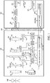
- FIG. 1 illustrates a configuration of an image-capturing system (hereinafter referred to as "a camera system”) including a camera body 200 as an image-capturing apparatus and an interchangeable lens 100 as an accessory apparatus that are a first embodiment (Embodiment 1) of the present invention.
- a camera system an image-capturing system
- a camera body 200 as an image-capturing apparatus
- an interchangeable lens 100 as an accessory apparatus that are a first embodiment (Embodiment 1) of the present invention.
- the camera body 200 and the interchangeable lens 100 transmit control commands and internal information to each other via their communicators described later.
- the communicators are compatible with various communication methods and switch their communication formats to the same one in synchronization with each other depending on types of data to be communicated and purposes of their communication, which enables selecting an optimum communication format for each of various situations.
- the interchangeable lens 100 and the camera body 200 are mechanically and electrically connected with each other via a mount 300 including a coupling mechanism.
- the interchangeable lens 100 receives power supply from the camera body 200 via a power source terminal (not illustrated) provided in the mount 300 and supplies, to various actuators and a lens microcomputer 111 described later, power sources necessary for their operations.
- the interchangeable lens 100 and the camera body 200 communicate with each other via communication terminals (illustrated in FIG. 2 ) provided in the mount 300.
- the interchangeable lens 100 includes an image-capturing optical system.
- the image-capturing optical system includes, from an object (OBJ) side, a field lens 101, a magnification-varying lens 102 for variation of magnification, a stop unit 114 for light amount control, an image-stabilizing lens 103 for image blur correction and a focus lens 104 for focusing.
- OBJ object
- the image-capturing optical system includes, from an object (OBJ) side, a field lens 101, a magnification-varying lens 102 for variation of magnification, a stop unit 114 for light amount control, an image-stabilizing lens 103 for image blur correction and a focus lens 104 for focusing.
- OBJ object
- magnification-varying lens 102 for variation of magnification
- a stop unit 114 for light amount control
- an image-stabilizing lens 103 for image blur correction
- a focus lens 104 for focusing.
- the magnification-varying lens 102 and the focus lens 104 are respectively held by lens holders 105 and 106.
- the lens holders 105 and 106 are guided by guide bars (not illustrated) movably in an optical axis direction in which an optical axis (illustrated by a broken line) of the image-capturing optical system extends and are driven in the optical axis direction respectively by stepping motors 107 and 108.
- the stepping motors 107 and 108 rotate in synchronization with drive pulses and respectively move the magnification-varying lens 102 and the focus lens 104.
- the image-stabilizing lens 103 is moved in a direction orthogonal to the optical axis of the image-capturing optical system to reduce image blur caused by user's hand jiggling or the like.
- the lens microcomputer 111 as an accessory controller controls various operations in the interchangeable lens 100.
- the lens microcomputer 111 receives, via the lens communicator 112 as an accessory communicator, control commands transmitted from the camera body 200 and transmission requests for lens data (accessory data) output therefrom.
- the lens microcomputer 111 performs various lens controls corresponding to the control commands and transmits lens data corresponding to the transmission requests via the lens communicator 112.
- the lens microcomputer 111 performs operations relating to the communication with the camera body 200 (that is, with a camera microcomputer 205 described later) according to a lens communication control program as a computer program.
- This embodiment employs asynchronous serial communication as a communication method between the lens microcomputer 111 and the camera microcomputer 205.
- the lens microcomputer 111 and the camera microcomputer 205 can share error information indicating that an abnormality of the communication therebetween, that is, a communication error occurs.
- the lens microcomputer 111 outputs, in response to a zoom command and a focus drive command among the control commands, a zoom drive signal and a focus drive signal to a zoom driver 119 and a focus driver 120 to cause them to drive the stepping motors 107 and 108, thereby performing a zoom process to control a magnification variation operation by the magnification-varying lens 102 and an AF (autofocus) process to control a focus operation by the focus lens 104.
- the interchangeable lens 100 is provided with a manual focus ring 130 that is rotationally operable by a user and a focus encoder 131 for detecting a rotational operation amount of the manual focus ring 130.
- the lens microcomputer 111 causes the focus driver 120 to drive the stepping motor 108 by a drive amount corresponding to the rotational operation amount of the manual focus ring 130 detected by the focus encoder 131 to drive the focus lens 104, thereby performing MF (manual focus).
- the lens microcomputer 111 outputs, depending on the input detection result from the A/D converter 123, a stop drive signal to a stop driver 121 so as to cause the stop driver 121 to drive a stop actuator 113, thereby controlling a light amount control operation of the stop unit 114.
- the image sensor 201 photoelectrically converts an object image formed by the image-capturing optical system in the interchangeable lens 100 to output an image-capturing signal as an analog electrical signal.
- a memory 210 is constituted by, for example, a DDR (Double Data Rate SDRAM).
- the memory 210 stores the digital image-capturing signal obtained using the image sensor 201 and the video signal produced by the image processor 203 and stores the lens data received from the lens microcomputer 111.
- the camera microcomputer 205 as a camera controller controls the camera body 200 in response to inputs from a camera operation unit 207 including an image-capturing instructing switch and various setting switches (not illustrated).
- the camera microcomputer 205 transmits, in response to a user's operation of a zoom switch (not illustrated), the control command relating to the magnification-varying operation of the magnification-varying lens 102 to the lens microcomputer 111 through a camera data transceiver 208b.
- the camera microcomputer 205 transmits, to the lens microcomputer 111 through the camera data transceiver 208b, the control command relating to the light amount control operation of the stop unit 114 depending on the luminance information and the control command relating to the focusing operation of the focus lens 104 depending on the focus information.
- the camera microcomputer 205 performs operations relating to the communication with the lens microcomputer 111 according to a camera communication control program as a computer program.
- the camera microcomputer 205 has a function of managing settings for the communication with the lens microcomputer 111 and a function of providing notices such as the transmission requests.
- the lens microcomputer 111 has a function of producing lens data and a function of transmitting the lens data.
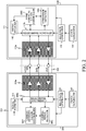
- the camera microcomputer 205 includes a camera communication interface circuit 208a, and the lens microcomputer 111 includes a lens communication interface circuit 112a.
- the camera microcomputer 205 (camera data transceiver 208b) and the lens microcomputer 111 (lens data transceiver 112b) communicate with each other through the communication terminals (illustrated by three boxes) provided in the mount 300 and the camera and lens communication interface circuits 208a and 112a.
- the camera and lens microcomputers 205 and 111 perform three-wire asynchronous serial communication using three channels.
- the camera data transceiver 208b and the camera communication interface circuit 208a constitute the camera communicator 208.
- the lens data transceiver 112b and the lens communication interface circuit 112a constitute the lens communicator 112.
- the three channels are a transmission request channel as a notification channel, a first data communication channel and a second data communication channel.
- the transmission request channel is used for providing the notices such as the transmission requests (transmission instructions) for the lens data and switch requests (switch instructions) for communication settings described later, from the camera microcomputer 205 to the lens microcomputer 111.
- the provision of the notice through the transmission request channel is performed by switching a signal level (voltage level) on the transmission request channel between High as a first level and Low as a second level.
- a transmission request signal provided to the transmission request channel is hereinafter referred to as "a request-to-send signal RTS".
- the first data communication channel is used for transmitting the lens data from the lens microcomputer 111 to the camera microcomputer 205.
- the lens data transmitted as a signal from the lens microcomputer 111 to the camera microcomputer 205 through the first data communication channel is hereinafter referred to as "a lens data signal DLC”.
- the second data communication channel is used for transmitting camera data from the camera microcomputer 205 to the lens microcomputer 111.
- the camera data transmitted as a signal from the camera microcomputer 205 to the lens microcomputer 111 through the second data communication channel is hereinafter referred to as "a camera data signal DCL".
- the camera data signal DCL includes various control commands and transmission request commands transmitted from the camera microcomputer 205 to the lens microcomputer 111.
- the lens data signal DLC includes various lens data transmitted from the lens microcomputer 111 to the camera microcomputer 205.
- the camera and lens microcomputers 205 and 111 set their communication speed beforehand and perform the communication (transmission and receipt) at a communication bit rate according to this setting.
- the communication bit rate indicates a data amount transferable per second and is expressed with a unit of bps (bits per second).
- the camera and lens microcomputers 205 and 111 communicate with each other by a full-duplex communication method enabling mutual transmission and receipt of data.
- the communication method between the camera body 200 and the interchangeable lens 100 may be performed by three-channel clock-synchronous serial communication instead of the three-channel asynchronous serial communication. Furthermore, in a case of performing large volume data transmission from the lens microcomputer 111 to the camera microcomputer 205, the clock-synchronous serial communication may be switched to the asynchronous serial communication. In this case, the notification channel may be used as a clock line for providing a clock signal from the camera microcomputer 205 to the lens microcomputer 111. This enables selectively using the two communication methods, that is, the asynchronous serial communication and the clock-synchronous serial communication without adding a new channel. In the clock-synchronous serial communication, the error information may be shared by communication commands.
- the camera microcomputer 205 includes a camera error detector 2051, a camera communication controller 2052 and a signal inverter 213.
- the camera error detector 2051 has a function of detecting presence and absence of a communication error (lens communication error) in the lens data signal DLC received from the lens microcomputer 111.
- the communication error detected by the camera error detector 2051 is at least one of a parity error and a framing error.
- the camera error detector 2051 may be hardware separate from the camera microcomputer 205, and also in this case the camera error detector 2051 is part of the camera controller.
- the signal inverter 213 inverts, when the camera error detector 2051 detects the communication error, part (specific bits) of the camera data signal DCL output from a transmission data parallel-serial converter 305 described later.
- the camera communication controller 2052 controls the camera data transceiver 208b, the camera error detector 2051 and the signal inverter 213.
- a clock generator 212 provided in the camera body 200 is constituted by a crystal oscillator or the like and outputs a clock signal with a predetermined frequency (or period).
- the clock signal generated by the clock generator 212 has a higher frequency than that of a baud rate generated by a baud rate generator 211 provided in the camera body 200.
- the baud rate generator 211 includes a frequency divider whose frequency division ratio is variable and divides the clock signal output from the clock generator 212 by a frequency division ratio corresponding to a baud-rate-generator setting value from the camera microcomputer 205 to generate the baud rate.
- a clock generator 144 and a baud rate generator 140 having the same functions as those of the clock generator 212 and the baud rate generator 211 are provided.
- the lens microcomputer 111 includes a lens error detector 1091, a lens communication controller 1092 and a signal inverter 142.
- the lens error detector 1091 has a function of detecting presence and absence of a communication error (camera communication error) in the camera data signal DCL received from the camera microcomputer 205.
- the communication error detected by the lens error detector 1091 is also at least one of the parity error and the framing error.
- the lens error detector 1091 may be hardware separate from the lens microcomputer 111, and also in this case the lens error detector 1091 is part of the lens controller (accessory controller).
- the signal inverter 142 inverts, when the lens error detector 1091 detects the communication error, part (specific bits) of the lens data signal DLC output from a transmission data parallel-serial converter 315 described later.
- the lens communication controller 1092 controls the lens data transceiver 112b, the lens error detector 1091 and the signal inverter 142.
- FIG. 3 illustrates a configuration of the camera data transceiver 208b in the camera microcomputer 205 and the lens data transceiver 112b in the lens microcomputer 111.
- the camera microcomputer 205 includes a CPU 205a as a core of the camera microcomputer 205, an RTS controller 301 and a transmission data buffer 302 as a camera data buffer constituted by a RAM or the like.
- the camera microcomputer 205 further includes a receipt data buffer 303 constituted by a RAM or the like and a buffer controller 304 that controls data storing and data read-out to and from the buffers 302 and 303.
- the lens microcomputer 111 includes a CPU 111a as a core of the lens microcomputer 111, an RTS detector 316 and a receipt data buffer 311 constituted by a RAM or the like.
- the camera microcomputer 111 further includes a transmission data buffer 312 as an accessory data buffer constituted by a RAM or the like and a buffer controller 313 that controls data storing and data read-out to and from the buffers 311 and 312.
- the camera data signal DCL to be transmitted from the camera microcomputer 205 to the lens microcomputer 111 is stored to the transmission data buffer 302.
- this camera data signal DCL of 128 bytes is first stored to the transmission data buffer 302 and then is transmitted to the lens microcomputer 111.
- the buffer controller 304 reads out the camera data signal DCL frame by frame from the transmission data buffer 302.
- the read camera data signal DCL of each frame is converted from a parallel data signal into a serial data signal by the parallel-serial converter 305 and is transmitted from the camera microcomputer 205 to the lens microcomputer 111 through the second data communication channel.
- the camera data signal DCL transmitted from the camera microcomputer 205 is converted from the serial data signal into a parallel data signal by the serial-parallel converter 314 in the lens microcomputer 111.
- the buffer controller 313 stores the camera data signal DCL converted into the parallel data signal to the receipt data buffer 311.
- the lens data signal DLC to be transmitted from the lens microcomputer 111 to the camera microcomputer 205 is stored to the transmission data buffer 312.
- this lens data signal DLC of 128 bytes is first stored to the transmission data buffer 312 and then is transmitted to the camera microcomputer 205.
- the buffer controller 313 reads out the lens data signal DLC frame by frame from the transmission data buffer 312.
- the read lens data signal DLC of each frame is converted from a parallel data signal into a serial data signal by the parallel-serial converter 315 and is transmitted from the lens microcomputer 111 to the camera microcomputer 205 through the first data communication channel.
- this embodiment provides the transmission data buffers 302 and 312 to both the camera and lens microcomputers 205 and 111. Therefore, in order to return to a normal communication state when the communication error occurs, it is necessary to clear (that is, erase the data signals stored in) these transmission data buffers 302 and 312. A method of sharing the error information will be described later.
- This first communication setting further includes, as described later, a communication setting (hereinafter referred to as "a BUSY addition mode") in which a busy frame is added and a communication setting (hereinafter referred to as “a non-BUSY addition mode”) in which the busy frame is not added.
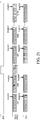
- FIGS. 4A to 4C illustrates waveforms of signals transmitted and received between the camera and lens microcomputers 205 and 111 in the first communication setting. An arrangement of procedures of the signal transmission and receipt is called a communication protocol.
- FIG. 4A illustrates signal waveforms of one frame as a minimum communication unit.
- the camera data signal DCL and the lens data signal DLC have mutually different parts in their data formats in the one frame.
- the lens data signal DLC in the one frame includes, as large parts, a data frame as a first frame and a BUSY frame as a subsequent frame.
- the data frame includes a start field, a data field and an end field.
- the signal level of the lens data signal DLC is held at High in a non-transmission state where data transmission is not performed.
- the lens microcomputer 111 sets the signal level to Low in one bit time period in order to provide a notice of a start of one frame transmission of the lens data signal DLC to the camera microcomputer 205.
- the start field is a time period for providing this start of one frame transmission to the camera microcomputer 205, and one bit time period as the start field is called "a start bit ST" in this embodiment.
- the start bit ST is provided as a head bit of each one frame of the lens data signal DLC.
- the start bit is not limited to the head bit and may be provided at an arbitrary bit.
- the parity bit PA is a bit indicating parity for the data D0 to D7.
- the camera and lens microcomputers 205 and 111 select beforehand which one of an odd parity and an even parity is to be used. In a case where the communication error is unnecessary to be considered, the parity bit PA may be omitted.
- the stop bit SP is a bit indicating an end of one frame transmission. Although this embodiment provides one bit as the stop bit SP, the stop bit SP may be constituted by two or more bits.
- the lens microcomputer 111 adds the BUSY frame after the stop bit SP.
- the BUSY frame indicates a time period of a communication standby request BUSY as a notice (hereinafter referred to as "a BUSY notice") from the lens microcomputer 111 to the camera microcomputer 205.
- the lens microcomputer 111 holds the signal level of the lens data signal DLC to Low until terminating the BUSY notice.
- a sum time period of the parity bit PA, the stop bit SP and the busy frame is corresponds to the end field.
- a data format is provided that forms one frame without adding the BUSY notice (BUSY frame). That is, the lens microcomputer 111 can select as the data format of the lens data signal DLC, depending on a process situation, one to which the BUSY notice is added and one to which the BUSY notice is not added.
- the signal waveform of "DLC (with BUSY)" and the signal waveform of "DLC (without BUSY)" both include bit positions B1 and B2.
- the camera microcomputer 205 selects one of these bit positions B1 and B2 as a BUSY determination position P for determining the presence and absence of the BUSY notice.
- this embodiment employs a data format that selects the BUSY determination position P from the bit positions B1 and B2.
- This data format enables addressing a problem that a process time from the transmission of the data frame of the lens data signal DLC until the determination of the presence of the BUSY notice (the lens data signal DLC is set to Low) is changed depending on a processing performance of the lens microcomputer 111.
- Whether to select the bit position B1 or B2 as the BUSY determination position P is set by the communication between the camera and lens microcomputers 205 and 111 before the data communication therebetween is performed.
- the BUSY determination position P is not necessary to be fixed at the bit position B1 or B2 and may be changed depending on processing capabilities of the camera and lens microcomputers 205 and 111.
- FIG. 4B illustrates signal waveforms in a case of performing continuous communication in the BUSY addition mode illustrated by "DLC (with BUSY)" in FIG. 4A .
- the BUSY notice (BUSY frame) from the lens microcomputer 111 is provided using the lens data signal DLC through the first data communication channel, and a subsequent communication is started after the BUSY notice is terminated.
- CMD1 represents a transmission request command that is transmitted as the camera data signal DCL from the camera microcomputer 205 to the lens microcomputer 111.
- the lens microcomputer 111 transmits, in response to receiving this transmission request command CMD1, lens data signals DT1 (DT1a and DT1b) of two bytes corresponding to the transmission request command CMD1 to the camera microcomputer 205.
- FIG. 4C illustrates signal waveforms in a case of performing communication with switching the communication setting (communication mode) between the BUSY addition mode and the non-BUSY addition mode.
- the communication is first performed in the BUSY addition mode and then performed in the non-BUSY addition mode.
- CMD2 represents a control command and a transmission request command that are transmitted as the camera data signal DCL from the camera microcomputer 205 to the lens microcomputer 111.
- FIG. 4C illustrates a case where the camera microcomputer 205 transmits the control and transmission request commands in one frame, the control and transmission request commands may be transmitted in mutually separate frames.
- the lens microcomputer 111 switches, in response to receiving the control command in the command CMD2, the communication mode from the BUSY addition mode to the non-BUSY addition mode. Then, the lens microcomputer 111 transmits, in response to receiving the transmission request command in the command CMD2, lens data signals DT2 (DT2a to DT2c) of three bytes corresponding to the transmission request command to the camera microcomputer 205.
- the camera microcomputer 205 sets, when an event for starting the communication with the lens microcomputer 111 occurs, a signal level of the request-to-send signal RTS to Low (in other words, asserts the request-to-send signal RTS) to provide the transmission request to the lens microcomputer 111.
- the lens microcomputer 111 having detected the transmission request through the assertion (Low) of the request-to-send signal RTS performs a process to produce the lens dada signal DLC to be transmitted to the camera microcomputer 205. Then, after a preparation for transmitting the lens data signal DLC is completed, the lens microcomputer 111 starts transmitting one frame of the lens data signal DLC through the first data communication channel.
- the lens microcomputer 111 starts the transmission of the lens data signal DLC within a time period mutually set by the camera and lens microcomputers 205 and 111 after the assertion of the request-to-send signal RTS. That is, for the lens microcomputer 111, a strict restriction is not provided that it is necessary to set the lens data to be transmitted before a first clock pulse is input thereto in a time period from the assertion of the request-to-send signal RTS to a start of the transmission of the lens data signal DLC.
- the lens microcomputer 111 having transmitted the data frame of the lens data signal DLC adds the BUSY frame to the lens data signal DLC in a case where the BUSY notice is necessary to be provided to the camera microcomputer 205.
- the camera microcomputer 205 monitors the presence or absence of the BUSY notice and prohibits the assertion of the request-to-send signal RTS for a subsequent transmission request while the BUSY notice is provided.
- the lens microcomputer 111 executes necessary processes in a time period where the communication from the camera microcomputer 205 is prohibited by the BUSY notice and terminates the BUSY notice after a subsequent communication preparation is completed.
- the assertion of the request-to-send signal RTS by the camera microcomputer 205 for the subsequent transmission request is permitted under a condition that the BUSY notice is terminated and the transmission of the data frame of the camera data signal DCL is completed.
- the lens microcomputer 111 in response to the assertion of the request-to-send signal RTS upon the communication starting event occurring in the camera microcomputer 205, the lens microcomputer 111 starts transmitting the data frame of the lens data signal DLC to the camera microcomputer 205.
- the camera microcomputer 205 having detected the start bit ST of the lens data signal DLC starts transmitting the data frame of the camera data signal DCL to the lens microcomputer 111.
- the lens microcomputer 111 adds, as needed, the BUSY frame to the data frame of the lens data signal DLC for providing the BUSY notice and then terminates the BUSY notice to end one frame communication process. In this communication process, the camera microcomputer 205 and the lens microcomputer 111 mutually transmit and receive one byte data.
- the camera microcomputer 205 performs the following processes in a subsequent frame in order to share the detection of the communication error by the camera error detector 2051 (that is, error information) with the lens microcomputer 111.
- the camera microcomputer 205 asserts the request-to-send signal RTS again (505) and receives the lens data signal DLC from the lens microcomputer 111 (506). Thereafter, the camera microcomputer 205 produces camera error information (hereinafter simply referred to as "error information”) in order to share the detection of the communication error with the lens microcomputer 111 (507).
- the camera microcomputer 205 (signal inverter 213) inverts the parity bit PA (0 or 1) that is the specific bit of the camera data signal DCL.
- the stop bit SP as another specific bit may be inverted.
- the camera data signal DCL thus produced as the error information (hereinafter referred to as "a camera error notice frame") is transmitted to the lens microcomputer 111.
- the lens microcomputer 111 receiving the camera error notice frame for the first time cannot determine whether or not the camera microcomputer 205 recognizes the detection of the communication error.
- the camera and lens microcomputers 205 and 111 perform the following communication process to share the detection of the communication error therebetween.
- the lens microcomputer 111 clears the transmission data buffer 312 in the lens data transceiver 112b to discard the lens data signal DLC to be subsequently transmitted to the camera microcomputer 205 (508).
- the camera microcomputer 205 asserts the request-to-send signal RTS in a subsequent frame to the camera error notice frame (509). In response to the assertion, the lens microcomputer 111 transmits the lens data signal DLC to the camera microcomputer 205 (510).
- the lens microcomputer 111 (signal inverter 142) inverts, in response to previously receiving the camera error notice frame, the parity bit PA as the specific bit of the lens data signal DLC to produce accessory error information (hereinafter simply referred to as "error information"). Then, the camera microcomputer 205 transmits the lens data signal DLC produced as the error information to the camera microcomputer 205 (511). The camera microcomputer 205 thus receives the error information from the lens microcomputer 111 (512).
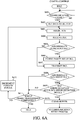
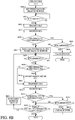
- the camera microcomputer 205 proceeds to step 602 to store the camera data signal DCL (whole frames) such as a transmission request command corresponding to the communication event to the transmission data buffer 302.
- the camera data signal DCL has a size depending on the transmission request command.
- the camera microcomputer 205 determines whether or not the determination is made that the lens data signal DLC from the lens microcomputer 111 includes the abnormality after transmitting the error information to the lens microcomputer 111. This determination is made for checking whether or not the communication error is detected by both the camera and lens microcomputers 205 and 111. If yes, the camera microcomputer 205 at step 610 clears the transmission data buffer 302.
- the lens microcomputer 111 receives the camera data signal DCL of one frame transmitted from the camera microcomputer 205. Then, at step 624, the lens microcomputer 111 determines whether or not the camera data signal DCL received at step 623 includes an abnormality. If the camera data signal DCL includes the abnormality, the lens microcomputer 111 at step 625 clears the transmission data buffer 312 and enters into a communication standby (IDLE) state. The reason therefor is as described above. The lens microcomputer 111 does not transmit the lens data signal DLC related to the camera data signal DCL received at step 623.
- IDLE communication standby
- step 624 if a determination is made at step 624 that the camera data signal DCL received at step 623 does not include the abnormality, the lens microcomputer 111 proceeds to step 626.
- the lens microcomputer 111 enters into the communication standby (IDLE) state. If the transmission has not been yet completed, the lens microcomputer 111 at step 635 performs an increment of an index specifying a frame to be subsequently transmitted among the frames of the lens data signal DLC remaining in the transmission data buffer 312 without being transmitted and then returns to step 627.
- IDLE communication standby
- a configuration of the camera system of Embodiment 2 is the same as that of Embodiment 1 described with referring to FIGS. 1 to 4C .
- FIGS. 7A and 7B description will be made of a process performed in Embodiment 2 when the communication error occurs in the first communication setting.
- FIG. 7A illustrates waveforms of signals transmitted and received between the camera and lens microcomputers 205 and 111 when the camera microcomputer 205 (camera error detector 2051) detects the communication error.
- the camera and lens microcomputers 205 and 111 perform processes 701 to 709.
- the lens microcomputer 111 transmits the lens data signal DLC of one frame to the camera microcomputer 205 (702).
- the camera microcomputer 205 transmits the camera data signal DCL of one frame to the lens microcomputer 111 (703).
- the camera error detector 2051 in the camera microcomputer 205 detects an inversion of the parity bit PA or the stop bit SP as the communication error (704), and the camera microcomputer 205 recognizes it as a parity error or a framing error.
- the camera microcomputer 205 performs the following processes in a subsequent frame in order to share the detection of the communication error by the camera error detector 2051 (that is, error information) with the lens microcomputer 111.
- the camera microcomputer 205 asserts the request-to-send signal RTS again (705) and receives the lens data signal DLC from the lens microcomputer 111 (706).
- the camera microcomputer 205 produces error information in order to share the detection of the communication error with the lens microcomputer 111 (707). Also in this embodiment, the camera microcomputer 205 inverts the parity bit PA (0 or 1) of the camera data signal DCL to produce the error information.
- the parity bit PA (0 or 1) of the camera data signal DCL
- the camera microcomputer 205 maintains the assertion of the request-to-send signal RTS when transmitting the camera data signal DCL as the error information to the lens microcomputer 111.
- the transmission of the error information from the camera microcomputer 205 to the lens microcomputer 111 with the assertion of the request-to-send signal RTS being maintained enables the lens microcomputer 111 to recognize that the error information is for sharing purpose. That is, the lens microcomputer 111 recognizes, through the assertion of the request-to-send signal RTS when receiving the error information, that the error information is an error detection notice from the camera microcomputer 205 to determine that the error information is for sharing purpose. On the other hand, the lens microcomputer 111 recognizes, through the negation of the request-to-send signal RTS when receiving the error information, that the error information is due to an actual abnormality occurring in the camera data signal DCL.
- the lens microcomputer 111 maintains the BUSY notice for the camera microcomputer 205 by the lens data signal DLC until completely clearing the transmission data buffer 312 and terminates the BUSY notice after completely clearing the transmission data buffer 312. On the other hand, the camera microcomputer 205 performs a subsequent communication after clearing the transmission data buffer 302.
- the above-described process enables, when the camera microcomputer 205 detects the communication error, both the camera and lens microcomputers 205 and 111 to simultaneously clear their transmission data buffers 302 and 312, which enables restarting a normal communication between the camera and lens microcomputers 205 and 111.
- FIG. 7B illustrates waveforms of signals transmitted and received between the camera and lens microcomputers 205 and 111 when the lens microcomputer 111 (lens error detector 1091) detects the communication error.
- the camera and lens microcomputers 205 and 111 perform processes 710 to 723.
- the lens microcomputer 111 transmits the lens data signal DLC to the camera microcomputer 205 (711).
- the camera microcomputer 205 transmits the camera data signal DCL to the lens microcomputer 111 (712).
- the lens error detector 1091 in the lens microcomputer 111 detects an inversion of the parity bit PA or the stop bit SP as the communication error (713), and the lens microcomputer 111 recognizes it as a parity error or a framing error.
- the lens microcomputer 111 determines whether or not the request-to-send signal RTS is asserted when detecting the communication error.
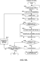
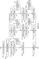
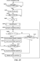
- Steps 801 to 812 are performed by the camera microcomputer 205, and steps 820 to 837 are performed by the lens microcomputer 111.
- the camera and lens microcomputers 205 and 111 each perform this process according to a communication control program as a computer program.
- step 803 the camera microcomputer 205 asserts the request-to-send signal RTS.
- the camera microcomputer 205 determines whether or not the lens data signal DLC of one frame (previous frame) received at step 804 includes an abnormality, that is, there is a communication error. If the lens data signal DLC includes the abnormality (the communication error is detected), the camera microcomputer 205 proceeds to step 806.
- the camera microcomputer 205 inverts the parity bit PA of one frame to be subsequently transmitted to the lens microcomputer 111 among the frames of the camera data signal DCL stored in the transmission data buffer 302 at step 802. Then, the camera microcomputer 205 at step 807 asserts the request-to-send signal RTS to maintain the assertion and at step 808 transmits the camera data signal DCL of the one frame whose parity bit PA is inverted to the lens microcomputer 111.
- the camera microcomputer 205 determines whether or not the lens data signal DLC of one frame (current frame) received at step 804 in the current routine includes an abnormality. If the lens data signal DLC includes the abnormality, the camera microcomputer 205 proceeds to step 810. At step 810, the camera microcomputer 205 clears the transmission data buffer 302. Thereafter, upon confirming that the BUSY notice of the lens data signal DLC has been terminated by the lens microcomputer 111, the camera microcomputer 205 performs a retransmission of the camera data signal DCL (that is, a communication retry) corresponding to the communication event occurring at step 801.
- a retransmission of the camera data signal DCL that is, a communication retry
- step 809 if the determination is made at step 805 that the lens data signal DLC includes no abnormality, the camera microcomputer 205 proceeds to step 811.
- step 811 the camera microcomputer 205 determines whether or not transmission of the whole frames of the camera data signal DCL stored in the transmission data buffer 302 at step 802 to the lens microcomputer 111 has been completed. If the transmission has been completed, the camera microcomputer 205 enters into a communication standby (IDLE) state. If the transmission has not been yet completed, the camera microcomputer 205 at step 812 performs an increment of an index specifying a frame to be subsequently transmitted among the frames of the camera data signal DCL remaining in the transmission data buffer 302 without being transmitted and then returns to step 803.
- IDLE communication standby
- the lens microcomputer 111 determines whether or not the request-to-send signal RTS is asserted by the camera microcomputer 205. If the request-to-send signal RTS is asserted, the lens microcomputer 111 at step 822 transmits, to the camera microcomputer 205, the one frame lens data signal DLC as the dummy data stored in the transmission data buffer 312 at step 820.
- the lens microcomputer 111 receives the camera data signal DCL of one frame transmitted from the camera microcomputer 205.
- the lens microcomputer 111 determines whether or not the camera data signal DCL received at step 823 includes an abnormality. If the camera data signal DCL includes the abnormality, the lens microcomputer 111 at step 825 determines whether or not the request-to-send signal RTS is asserted.
- the lens microcomputer 111 determines that the abnormality of the camera data signal DCL is error information transmitted from the camera microcomputer 205 for sharing purpose and then proceeds to step 826. At step 826, the lens microcomputer 111 clears the transmission data buffer 312 and enters into the communication standby (IDLE) state.
- the lens microcomputer 111 waits for the assertion of the request-to-send signal RTS by the camera microcomputer 205. If the request-to-send signal RTS is asserted, the lens microcomputer 111 at step 829 determines whether or not the camera data signal DCL of a previous frame received from the camera microcomputer 205 at step 832 described later in a previous routine includes an abnormality. If the request-to-send signal RTS has been asserted at step 825 or at step 834 described later in the previous routine, the abnormality included in the camera data signal DCL of the previous frame means the error information produced by the camera microcomputer 205 for sharing purpose.
- the lens microcomputer 111 determines whether or not the camera data signal DCL of a current frame received at step 832 in this (current) routine includes an abnormality. If the camera data signal DCL includes the abnormality, the lens microcomputer 111 proceeds to step 834 to determine whether or not the request-to-send signal RTS is asserted. If the request-to-send signal RTS is asserted, the lens microcomputer 111 determines that the abnormality included in the camera data signal DCL of the current frame is error information produced by the camera microcomputer 205 for sharing purpose and then proceeds to step 835.
- the lens microcomputer 111 determines whether or not transmission of the whole frames of the lens data signal DLC stored in the transmission data buffer 312 at step 827 to the camera microcomputer 205 has been completed. If the transmission has been completed, the lens microcomputer 111 enters into the communication standby (IDLE) state. If the transmission has not been yet completed, the lens microcomputer 111 at step 837 performs an increment of an index specifying a frame to be subsequently transmitted among the frames of the lens data signal DLC remaining in the transmission data buffer 312 without being transmitted and then returns to step 828.
- IDLE communication standby
- This embodiment enables, when the camera microcomputer 205 or the lens microcomputer 111 detects the communication error, the camera and lens microcomputers 205 and 111 to share the detection of the communication error (that is, the error information) with a smaller number of processes than in Embodiment 1. Thereby, the camera and lens microcomputers 205 and 111 can clear their transmission data buffers 301 and 312 immediately after the communication error occurs and restart the communication therebetween in a short time.
- Embodiment 3 is a modified example of Embodiment 1 and is an embodiment of the following image-capturing apparatus.
- the image-capturing apparatus includes a camera controller having a function of detecting an accessory communication error in accessory data received from an accessory apparatus.
- the lens controller is configured to, when detecting the accessory communication error, transmit camera error information to the accessory apparatus, during transmission of camera data in response to receiving the accessory data, by inverting a specific bit of the camera data.
- the communication error is the parity error or the framing error.
- the camera controller is further configured to, when transmitting the camera data in response to receiving the accessory data, change the specific bit depending on a delay amount of the transmission of the camera data with respect to the receipt of the accessory data. Moreover, the camera controller is configured to change the specific bit depending on a type of the communication error (that is, depending on whether the parity error or the framing error).
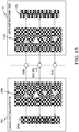
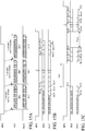
- FIG. 10A illustrates waveforms of signals transmitted and received between the camera and lens microcomputers 205 and 111 in a case where no communication error occurs in this embodiment.
- the case where no communication error occurs in this embodiment is a case where a delay amount t1000 of a time at which the camera microcomputer 205 starts transmitting the camera data signal DCL with respect to a time at which the camera microcomputer 205 starts receiving the lens data signal DLC is less than 1 bit.
- the delay amount t1000 is a time period (bit shift number) from a time of receiving the start bit ST of the lens data signal DLC to a time of transmitting the start bit ST of the camera data signal DCL.
- FIGS. 10B and 10C illustrate waveforms of signals transmitted and received between the camera and lens microcomputers 205 and 111 when the parity error as the communication error occurs in this embodiment.
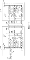
- the camera microcomputer 205 performs, after starting receiving the lens data signal DLC from the lens microcomputer 111 at step 604 illustrated in FIG. 6A in Embodiment 1, processes at step (each abbreviated by S in FIG. 9 ) 901 and steps subsequent thereto, instead of steps 605 to 607 in illustrated in FIG. 6A .
- the camera microcomputer 205 has already received the start bit ST and the data D7 to D0 of the lens data signal DLC and has already transmitted the start bit ST and the data D7 to D0 of one frame of the lens data signal DLC. That is, the process at step 901 is started during the receipt of the lens data signal DLC and during the transmission of the one frame of the camera data signal DCL.
- the camera microcomputer 205 initializes an inversion flag indicating whether or not to invert the parity bit PA and the stop bit SP of the camera data signal DCL.
- the initialized inversion flag becomes OFF indicating that an inversion of the parity bit PA and the stop bit SP is not performed.
- the camera microcomputer 205 acquires the delay amount of the transmission time (start bit ST) of the camera data signal DCL with respect to the received lens data signal DLC and performs a selected one of the following three processes that is selected depending on the acquired delay amount.
- the delay amount may be acquired as a delay bit number predetermined between the camera and lens microcomputers 205 and 111 or may be acquired by providing a delay amount detector (not illustrated) in the camera microcomputer 205 and by detecting the delay amount by the delay amount detector.
- the camera microcomputer 205 performs a first process of the three processes when the acquired delay amount is less than 1 bit as illustrated in FIG. 10A ; the first process is for the parity error of the lens data signal DLC and includes processes at steps 903 to 907. Specifically, as illustrated by 1011 in FIG. 10A , the first process inverts, depending on a receipt result of the parity bit PA of the lens data signal DLC, the stop bit SP of the camera data signal DCL.
- the camera microcomputer 205 performs a second process of the three processes when the acquired delay amount is 1 bit as illustrated in FIGS. 10B and 11A ; the second process is for the parity error and the framing error of the lens data signal DLC and includes processes at steps 910 to 916.
- the second process inverts, depending on the receipt result of the parity bit PA of the lens data signal DLC, the parity bit PA or the stop bit SP of the camera data signal DCL.
- the second process inverts, depending on a receipt result of the stop bit SP of the lens data signal DLC, the parity bit PA or the stop bit SP of the camera data signal DCL.
- the camera microcomputer 205 performs a third process of the three processes when the acquired delay amount is 2 bit (or more) as illustrated in FIGS. 10C and 11B ; the third process is for the parity error and the framing error of the lens data signal DLC and includes processes at steps 920 to 926. Specifically, as illustrated by 1014 and 1016 in FIG. 10C , the third process inverts, depending on the receipt result of the parity bit PA of the lens data signal DLC, the parity bit PA or the stop bit SP of the camera data signal DCL.
- the third process inverts, depending on the receipt result of the stop bit SP of the lens data signal DLC, the parity bit PA or the stop bit SP of the camera data signal DCL.
- the camera microcomputer 205 receives the parity bit PA of the lens data signal DLC from the lens microcomputer 111 and transmits the parity bit PA of the camera data signal DCL to the lens microcomputer 111.
- step 904 the camera microcomputer 205 determines whether or not the parity error is detected by the camera error detector 2051. If the parity error is detected, the camera microcomputer 205 proceeds to step 905, and otherwise proceeds to step 906.
- the camera microcomputer 205 changes the inversion flag to ON indicating that the inversion of the stop bit SP of the camera data signal DCL is performed. Then, the camera microcomputer 205 proceeds to step 906. At step 906, the camera microcomputer 205 receives the stop bit SP of the lens data signal DLC.
- the camera microcomputer 205 transmits, depending on the inversion flag (ON or OFF), the stop bit SP of the camera data signal DCL to the lens microcomputer 111. Thereafter, the camera microcomputer 205 proceeds to step 608 in FIG. 6A .
- the camera microcomputer 205 proceeding to step 608 determines, as described in Embodiment 1, whether or not the lens data signal DLC of one frame (current frame) received at step 604 in the current routine includes an abnormality. If the lens data signal DLC includes the abnormality, the camera microcomputer 205 performs the processes at step 609 and steps subsequent thereto. This applies to the second and third processes below.
- the camera microcomputer 205 receives the parity bit PA of the lens data signal DLC from the lens microcomputer 111.
- the camera microcomputer 205 determines whether or not the parity error is detected by the camera error detector 2051. If the parity error is detected, the camera microcomputer 205 proceeds to step 912, and otherwise proceeds to step 913.
- the camera microcomputer 205 changes the inversion flag to ON indicating that the inversion of at least one of the parity bit PA and the stop bit SP of the camera data signal DCL is performed and then proceeds to step 913.
- the inversion herein aims to intentionally bring the signal waveform of the camera data signal DCL into an abnormal (error) state, so that the inversion may be performed either on the parity bit PA or the stop bit SP.
- the camera microcomputer 205 receives the stop bit SP of the lens data signal DLC from the lens microcomputer 111. On the other hand, the camera microcomputer 205 transmits, depending on the inversion flag (ON or OFF), the parity bit PA of the camera data signal DCL to the lens microcomputer 111.
- the camera microcomputer 205 determines whether or not the framing error is detected by the camera error detector 2051. If the framing error is detected, the camera microcomputer 205 proceeds to step 915, and otherwise proceeds to step 916.
- the camera microcomputer 205 changes the inversion flag to ON indicating that the inversion of the stop bit SP of the camera data signal DCL is performed and then proceeds to step 916.
- the camera microcomputer 205 transmits, depending on the inversion flag (ON or OFF), the stop bit SP of the camera data signal DCL to the lens microcomputer 111. Thereafter, the camera microcomputer 205 proceeds to step 608 in FIG. 6A .
- the camera microcomputer 205 receives the parity bit PA of the lens data signal DLC from the lens microcomputer 111.
- the camera microcomputer 205 determines whether or not the parity error is detected by the camera error detector 2051. If the parity error is detected, the camera microcomputer 205 proceeds to step 922, and otherwise proceeds to step 923.
- the camera microcomputer 205 changes the inversion flag to ON indicating that the inversion of at least one of the parity bit PA and the stop bit SP of the camera data signal DCL is performed and then proceeds to step 923.
- the inversion herein, as well as the second process, aims to intentionally bring the signal waveform of the camera data signal DCL into an abnormal (error) state, so that the inversion may be performed either on the parity bit PA or the stop bit SP.
- the camera microcomputer 205 receives the stop bit SP of the lens data signal DLC from the lens microcomputer 111.
- the camera microcomputer 205 determines whether or not the framing error is detected by the camera error detector 2051. If the framing error is detected, the camera microcomputer 205 proceeds to step 925, and otherwise proceeds to step 926.
- the camera microcomputer 205 changes, due to the same reason at step 922, the inversion flag to ON indicating that the inversion of at least one of the parity bit PA and the stop bit SP of the camera data signal DCL is performed and then proceeds to step 926.
- the camera microcomputer 205 transmits, depending on the inversion flag (ON or OFF), the parity bit PA and the stop bit SP of the camera data signal DCL to the lens microcomputer 111. Thereafter, the camera microcomputer 205 proceeds to step 608 in FIG. 6A .
- any one of the above three process completes transmission of one frame of the camera data signal DCL to the lens microcomputer 111. All the above three processes are not necessarily performed, that is, it is only necessary that any one of them be performed. In this case, it is necessary to predetermine the delay amount between the camera and lens microcomputers 205 and 111. In other words, it is only necessary that an appropriate one of the three processes for the predetermined delay amount be performed.
- the camera microcomputer 205 intentionally generates the error state in one frame of the camera data signal DCL when the communication error occurs in the lens data signal DLC received from the lens microcomputer 111.
- the camera microcomputer 205 thereby enables notifying the lens microcomputer 111 of the occurrence of the communication error in the received lens data signal DLC.
- the lens microcomputer 111 can detect the error state of the camera date signal DCL at the lens error detector 1091 and perform a predetermined recovery process, which enables promptly restarting a normal communication.
- the predetermined recovery process for example, the lens microcomputer 111 having detected the error state of the camera data signal DCL starts preparing for retransmitting the lens data signal DLC corresponding to the occurrence time of the communication error. Then, the lens microcomputer 111 retransmits the prepared lens data signal DLC in a subsequent communication with the camera microcomputer 205 (that is, in response to a subsequent assertion of the request-to-send signal RTS).
- the communication process in this embodiment enables, when the communication error occurs in the burst communication described in Embodiment 1, restarting the burst communication from a frame in which the communication error has occurred, without a necessity of restarting the burst communication from its beginning.
- the camera microcomputer 205 having detected the communication error in the lens data signal DLC can notify the lens microcomputer 111 of the occurrence of the communication error in a frame of the camera data signal DCL corresponding to that of the lens data signal DCL where the communication error has been detected. That is, the camera microcomputer 205 inverts, during the transmission of one frame of the camera data signal DCL, the parity bit PA or the stop bit SP in that one frame, which enables notifying the lens microcomputer 111 of the occurrence of the communication error.
- this embodiment enables, as compared with Embodiment 1, earlier notifying the lens microcomputer 111 of the occurrence of the communication error and earlier restarting a normal communication.
- Embodiment 4 performs the burst communication by the asynchronous serial communication in the communication setting (non-BUSY addition mode) in which the BUSY notice (BUSY frame) is not added.
- the non-BUSY addition mode enables large volume data burst communication at a higher speed as compared with the BUSY addition mode in which the BUSY frame is added.
- this embodiment enables an image-capturing apparatus to promptly acquiring large volume data from an interchangeable lens (accessory apparatus) and to promptly restart the communication after the communication error occurs.
- a camera controller of the image-capturing apparatus has, in the first communication setting, a function of performing a connection confirmation communication for confirming a connection between the image-capturing apparatus and the accessory apparatus and a function of detecting a communication error in accessory data received from the accessory apparatus.
- the camera controller is characterized by being capable of changing a period (cycle) of performing the connection confirmation communication depending on a number of times (frequency) of detecting the communication errors.
- the camera controller is further characterized by being capable of changing the communication setting between the first and second communication settings depending on the number of times of detecting the communication errors.
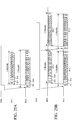
- FIG. 12 illustrates waveforms of signals transmitted and received between the camera and lens microcomputers 205 and 111 in the non-BUSY addition mode in the first communication setting.
- FIG. 12A illustrates signal waveforms when three frames in which each one frame is a minimum communication unit are continuously communicated.
- the BUSY notice is not added to the lens data signal DLC.
- one frame of the lens data signal DLC has a data format formed only by the data frame, that is, not including the BUSY frame. Therefore, in the non-BUSY addition mode, the lens microcomputer 111 cannot provide the BUSY notice to the camera microcomputer 205.
- This data format is used for performing the burst communication as continuous communication in which each interval between frames is shortened so as to transmit relatively large volume data between the camera microcomputer 205 and the lens microcomputer 111. That is, the non-BUSY addition mode enables large volume data communication at a higher speed.
- each frame of the lens data signal DLC includes two stop bits SP as final bits, which is more than that of each frame of the camera data signal DCL.
- This difference in stop bit number makes a bit length of one frame of the lens data signal DLC longer than that of one frame of the camera data signal DCL. The reason for the longer bit length will be described later.
- the camera microcomputer 205 asserts the request-to-send signal RTS when an event for starting the communication with the lens microcomputer 111 occurs. Thereafter, in the non-BUSY addition mode in which it is unnecessary to negate the request-to-send signal RTS at each frame, the camera microcomputer 205 maintains the assertion of the request-to-send signal RTS while performing continuous data communication (transmission and receipt) with the lens microcomputer 111.
- the lens microcomputer 111 performs, in response to detecting a transmission request by the assertion of the request-to-send signal RTS, a process for producing the lens data signal DLC to be transmitted to the camera microcomputer 205. Then, after a preparation for transmitting the lens data signal DLC is completed, the lens microcomputer 111 starts transmitting a first frame DL1 of the lens data signal DLC to the camera microcomputer 205 through the first data communication channel.
- the lens microcomputer 111 having transmitted the data frame of the first frame of the lens data signal DLC rechecks the request-to-send signal RTS. If the request-to-send signal RTS is asserted, the lens microcomputer 111 transmits, after the first frame whose transmission has been completed, a second frame DL2 of the lens data signal DLC to the camera microcomputer 205. In this way, while the assertion of the request-to-send signal RTS is maintained by the camera microcomputer 205, the lens microcomputer 111 continuously transmits the n frames DL1 to DLn of the lens data signal DLC to the camera microcomputer 205. Then, if the transmission of the n frames indicated in the data size information is completed, the transmission of the lens data signal DLC is stopped.
- the camera microcomputer 205 transmits, in response to detecting the start bits ST of the frames of the lens data signal DLC, n frames DC1 to DCn of the camera data signal DCL through the second data communication channel.
- the assertion of the request-to-send signal RST maintained by the camera microcomputer 205 enables continuous transmission and receipt of the lens and camera data signals DLC and DCL whose each frame number corresponds to the data size information.
- the camera microcomputer 205 temporarily stores the n frames of the lens data signal DLC continuously received from the lens microcomputer 111 to the receipt data buffer 303 through the serial-parallel converter 306.
- the DMA controller 307 transfers the n frames of the lens data signal DLC stored in the receipt data buffer 303 to the memory 210 to finally store these n frames to the memory 210. Therefore, to receive a larger data amount of the lens data signal DLC than a capacity of the receipt data buffer 303, it is necessary to transfer the lens data signal DLC stored before in the receipt data buffer 303 to the memory 210 so as to secure a free space of the receipt data buffer 303.
- the DMA controller 307 cannot access the memory 210 due to a processing situation of the signal processor 203 provided in the camera body 200, it is impossible to transfer the n frames of the lens data signal DLC continuously received from the lens microcomputer 111 to the memory 210.
- the rewritten data is not stored to the memory 210.
- FIG. 12C illustrates signal waveforms in a case where, during the continuous data communication illustrated in FIG. 12B , the camera microcomputer 205 instructs a suspension of the communication. Also in this case, in response to the assertion of the request-to-send signal RTS by the camera microcomputer 205, the lens microcomputer 111 starts transmitting the lens data signal DLC. Then, in response to detecting the start bit ST of the lens data signal DLC, the camera microcomputer 205 starts transmitting the camera data signal DCL.
- T represents a communication suspension time period where the suspension of the communication is instructed by the camera microcomputer 205.
- the camera microcomputer 205 instructs the lens microcomputer 111 to suspend the communication (that is, provides a communication suspension instruction to the lens microcomputer 111) by temporarily negating the request-to-send signal RTS.
- the lens microcomputer 111 suspends transmitting the lens data signal DLC after completing transmitting a frame incompletely transmitted at the time of detecting the negation (this last transmitted frame is illustrated as DL6 in FIG. 12C and hereinafter referred to as "a suspension frame").
- the camera microcomputer 205 In response to the transmission suspension of the camera data signal DLC, the camera microcomputer 205 also suspends transmitting the camera data signal DCL after completing transmitting a frame (illustrated as DC6 in FIG. 12C ) thereof corresponding to the suspension frame of the lens data signal DLC.
- Such communication control enables, even when the communication suspension instruction is provided during the continuous data communication, managing so as to make a transmitted frame number of the lens data signal DLC equal to that of the camera data signal DCL, that is, so as to synchronize the transmissions of the lens and camera data signals DLC and DCL.
- the camera microcomputer 205 In response to termination of the communication suspension event, the camera microcomputer 205 is allowed to assert the request-to-send signal RTS again to instruct the lens microcomputer 111 to restart the communication (that is, provides a communication restart instruction to the lens microcomputer 111).
- the lens microcomputer 111 restarts, in response to the communication restart instruction, transmitting the lens data signal DLC from a frame subsequent to the suspension frame (this subsequent frame is illustrated as DL7 in FIG. 12C and hereinafter referred to as "a restart frame").
- the camera microcomputer 205 restarts transmitting the camera data signal DCL from a frame DC7 thereof corresponding to the restart frame of the lens data signal DLC.
- the camera microcomputer 205 temporarily negates the request-to-send signal RTS to suspend the communication with the lens microcomputer 111. Then, if a received frame number of the lens data signal DLC at the time of the suspension is less than the frame number indicated in the data size information, the camera microcomputer 205 is allowed to restart receiving the lens data signal DLC from the lens microcomputer 111.
- FIG. 16A illustrates a relation of frames of the camera and lens data signals DCL and DLC when the camera and lens data signals DCL and DLC have the same bit length of one frame (data frame) and the bit rate of the camera data signal DCL is slower than that of the lens data signal DLC.
- Arrows in FIG. 16A illustrates which start bit ST of the lens data signal DLC is detected by the camera microcomputer 205 and which frame of the camera data signal DCL is transmitted from the camera microcomputer 205 to the lens microcomputer 111.
- the bit rate of the camera data signal DCL is slower than that of the lens data signal DLC, delays of the frames of the camera data signals DCL with respect to the frames of the lens data signal DLC are gradually increased.
- the camera and lens microcomputers 205 and 111 are performing continuous data communication, so that gaps (non-communication time period) are provided between the frames. Accordingly, accumulation of the delays causes a shift of one frame or more between the camera and lens data signals DCL and DLC, which generates a difference between the transmitted frame numbers of the camera and lens data signals DCL and DLC.
- the above shift between the camera and lens data signals DCL and DLC causes the camera microcomputer 205 to skip the start bit ST of one frame of the lens data signal DLC, which generates a time period corresponding to about one frame where the camera data signal DCL is not transmitted to the lens microcomputer 111.
- Such a situation makes it difficult to manage the transmitted frame numbers (communicated data amounts) between the camera and lens microcomputers 205 and 111 and makes the data communication therebetween impossible.
- this embodiment provides, as illustrated in FIGS. 12A and 16B , a greater number of the stop bits SP in each frame of the lens data signal DLC than that in each frame of the camera data signal DCL.
- each frame of the camera data signal DCL includes one stop bit SP
- each frame of the lens data signal DLC includes two stop bits SP.
- the data formats of the lens and camera data signals DLC and DCL are mutually the same except for the stop bit number.
- the difference in stop bit number makes the bit number of one frame (data frame) of the lens data signal DLC greater than that of one frame of the camera data signal DCL.
- the difference in stop bit number makes the bit length of one frame of the lens data signal DLC longer than that of one frame of the camera data signal DCL.
- the camera microcomputer 205 tries communication with the interchangeable lens 100 (lens microcomputer 111) using the asynchronous serial communication, the communication does not succeed. In such a case, the camera microcomputer 205 is desirable to use the clock-synchronous serial communication.
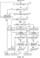
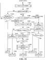
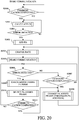
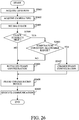
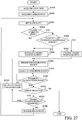
- FIG. 23 is a flowchart illustrating an error process performed by the camera microcomputer 205 when the communication error occurs in the second communication setting.
- the camera microcomputer 205 executes this process according to a communication control program as a computer program.
- the communication error first detected is a checksum error.
- the first detected communication error may be an error other than the checksum error.
- Steps 2000 to 2007, step 2009 and step 2011 in FIG. 23 are the same as steps 2000 to 2007, step 2009 and step 2011 in FIG. 20 of Embodiment 4.
- the camera microcomputer 205 having determined at step 2011 that the current burst communication has been completed proceeds to step 2302.
- the camera microcomputer 205 sets (changes) the burst length of the first and second lens data signals DLC and DLC2 to be transmitted in the subsequent burst communication to the burst length calculated at step 2301.
- the camera microcomputer 205 at step 2303 terminates the addition of the parity bit and then returns to step 2004. Thereby, at next step 2005, the subsequent burst communication whose burst length is changed is performed.
- the camera microcomputer 205 having determined at step 2007 that the current burst communication has been completed and proceeding to step 2303 terminates the addition of the parity bit to the first and second lens data signals DLC and DLC2 to be transmitted in the subsequent burst communication. Then, the camera microcomputer 205 returns to step 2004. The camera microcomputer 205 changes the communication bit rate changed at step 2004 to its original communication bit rate.
- the camera microcomputer 205 discontinues the burst communication at the second frame. Then, as illustrated in FIG. 21 , the camera microcomputer 205 adds the parity bit PA to all the frames and promptly restart the burst communication. Thereafter, when the parity error frame number becomes equal to or more than the predetermined number, the camera microcomputer 205 shortens the burst length of the subsequent burst communication without addition of the parity bit.
- the burst length may be changed to be longer than the changed burst length, for example, to the normal burst length.
- This embodiment changes the burst length depending on the number of times of detecting the communication error so at to make the detection of the communication error easier, which enables shortening the time required for the burst communication.
- this embodiment performs a communication process (communication control) capable of improving the effective communication rate while increasing the communicated data amount
- Changing the data field configuration includes, for example, changing a data length (bit number) of that field. It is desirable to change the data field configuration such that the phase relation between the transmitting data output time and the received data sampling time is within the predetermined allowable range.
- the camera body 200 and the interchangeable lens 100 have, for example, the same configurations as those illustrated in FIG. 2 . That is, the camera body 200 and the interchangeable lens 100 respectively have the clock generators 212 and 144, the baud rate generators 211 and 140.
- the camera microcomputer 205 and the lens microcomputer 111 respectively include the camera error detector 2051 and the lens error detector 1091.
- FIG. 25A illustrates waveforms of the lens data signal DLC and the camera data signal DCL when the data field in one frame of each data signal is expanded in the first communication setting described in Embodiment 1.
- the one frame of each of the lens data signal DLC and the camera data signal DCL includes the start field, an expanded data field and the end field.
- the expanded data field in this embodiment is constituted by data of 12 bits from a second bit to a thirteenth bit.
- the data bits are arranged in an MSB-first format starting from a highest-order data bit D11 and continuing to data bits D10, D9, D8, D7, D6, D5, D4, D3, D2 and D1 in this order and ending with a lowest-order data bit D0.
- the start bit and the end field are the same as those described in Embodiment 1.
- the camera microcomputer 205 Prior to starting this communication, the camera microcomputer 205 notifies the lens microcomputer 111, by the camera data signal DCL of one frame illustrated in FIG. 4A , of data size information (two frames in this description) of the camera data signal DCL to be transmitted. Furthermore, the camera microcomputer 205 notifies the camera microcomputer 111 of a frame configuration (described later) including the data field configuration.
- the camera microcomputer 205 asserts the request-to-send signal RTS when an event for starting the communication with the lens microcomputer 11 occurs. Thereafter, in the non-BUSY addition mode in which it is unnecessary to negate the request-to-send signal RTS at each frame, the camera microcomputer 205 maintains the assertion of the request-to-send signal RTS while performing continuous data communication with the lens microcomputer 111.
- the lens microcomputer 111 performs, in response to detecting a transmission request by the assertion of the request-to-send signal RTS, a process for producing the lens data signal DLC to be transmitted to the camera microcomputer 205. Then, after a preparation for transmitting the lens data signal DLC is completed, the lens microcomputer 111 starts transmitting a first frame DL1 of the lens data signal DLC to the camera microcomputer 205 through the first data communication channel.
- the lens microcomputer 111 having transmitted the data frame of the first frame of the lens data signal DLC rechecks the request-to-send signal RTS. If the request-to-send signal RTS is asserted, the lens microcomputer 111 transmits, after the first frame whose transmission has been completed, a second frame DL2 of the lens data signal DLC to the camera microcomputer 205. Then, if the transmission of the two frames indicated in the data size information is completed, the camera microcomputer 205 negates the request-to-send signal RTS, and thereby the transmission of the lens data signal DLC is stopped.
- the data field configuration illustrated in FIG. 25B in this embodiment is equal to that illustrated in FIG. 12A in data amount of 24 bits (3 bytes).
- the data field configuration in FIG. 12A requires three frames for transmitting the 24-bit data
- the data field configuration in FIG. 25B requires two frames for transmitting the 24-bit data. Therefore, this embodiment enables reducing numbers of the start bits ST and the stop bits SP inserted into the camera and lens data signals DCL and DLC as compared with the case of FIG. 12A , which increases the effective communication rate.
- FIG. 26 is a flow chart illustrating a communication process performed by the camera microcomputer 205 in this embodiment.
- the camera microcomputer 205 executes this process according to a communication control program as a computer program.
- the camera microcomputer 205 performs communication with the lens microcomputer 111 to acquire, from the lens microcomputer 111, a lens ID as information on a type of the interchangeable lens 100.
- the camera microcomputer 205 further acquires, from the lens microcomputer 111, information on stability of the clock signal generated by the clock generator 144.
- the information on the stability is hereinafter referred to as "a lens clock stability”.
- the camera microcomputer 205 acquires, from the lens microcomputer 111, information on a temperature detected by a temperature sensor (not illustrated) provided in the interchangeable lens 100.
- the information on the temperature is hereinafter referred to as "a lens temperature”.
- the camera microcomputer 205 acquires, from the lens microcomputer 111, information on a baud rate range supported by the interchangeable lens 100.
- the information on the baud rate range is hereinafter referred to as "a lens baud rate range”.
- These lens ID, lens clock stability, lens temperature and lens baud rate range are included in individual information of the interchangeable lens 100.
- the individual information is hereinafter referred to as "lens information”.
- the camera microcomputer 205 performs the communication for acquiring the lens information from the lens microcomputer 111 with an initial format predetermined therebetween.
- the baud rate in this communication is an initial baud rate predefined therebetween.
- the lens ID is stored in a RAM (not illustrated) provided in the interchangeable lens 100.
- the camera microcomputer 205 is able to determine, from the lens ID, which functions the attached interchangeable lens 100 supports.
- the camera microcomputer 205 acquires camera information as individual information of the camera body 200 indicating its performances.
- the camera information includes information on stability of the clock signal generated by the clock generator 212 and information on temperature detected by a temperature sensor (not illustrated) provided in the camera body 200.
- the information on the stability is hereinafter referred to as “a camera clock stability”
- the information on the temperature is hereinafter referred to as "a camera temperature”.
- the camera information further includes information on a baud rate range supported by the camera body 200.
- the information on the baud rate range is hereinafter referred to as "a camera baud rate range”.
- the camera microcomputer 205 sets, depending on the lens information acquired at step 2601 and the camera information acquired at step 2602, a baud rate to be used.
- the lens information includes the lens baud rate range
- the camera information includes the camera baud rate range.
- the camera microcomputer 205 sets, in a baud rate range included in both the lens and camera baud rate ranges, a baud rate appropriate for a type of data, an operation mode of the camera body 200 and the like.
- the camera microcomputer 205 notifies the lens microcomputer 111 of the set baud rate.
- the camera microcomputer 205 notifies the baud rate generator 211 of the set baud rate to change a baud rate setting value of the baud rate generator 211 to the set baud rate.
- the camera microcomputer 205 checks the lens clock stability included in the lens information and the camera clock stability included in the camera information. If the lens and camera clock stabilities are lower than a predetermined level, the camera microcomputer 205 proceeds to step 2606. If the lens and camera clock stabilities are higher than (or equal to) the predetermined level, the camera microcomputer 205 proceeds to step 2605.
- the camera microcomputer 205 sets, as the above-mentioned frame configuration that is a configuration of one frame, an initial frame configuration that is the frame configuration illustrated in FIG. 4A . This is because, when the lens and camera clock stabilities lower than the predetermined level (out of their allowable range), the data field cannot be expanded. Then, the camera microcomputer 205 proceeds to step 2608.
- the camera microcomputer 205 changes the frame configuration to an expanded frame configuration that is the frame configuration illustrated in FIG. 25A . This is because the lens and camera clock stabilities are within the allowable range and the temperature condition is satisfied, so that the data field can be expanded.
- the bit number of the data field can be arbitrary set as long as the phase relation between the transmitting data output time and the received data sampling time of the camera and lens microcomputers 205 and 111 is within the predetermined allowable range.
- the camera microcomputer 205 proceeds to step 2608.
- the camera microcomputer 205 also changes the end field configuration.
- the camera microcomputer 205 notifies the lens microcomputer 111 of the frame configuration set at step 2606 or step 2607.
- the frame configuration notified of includes not only the bit number of the data field, but also the end field configuration.
- the frame configuration notified of includes the frame number communicated by the burst communication.
- the camera microcomputer 205 asserts the request-to-send signal RTS to cause the lens microcomputer 111 to start transmitting the lens data signal DLC and, in response to receiving the lens data signal DLC, the camera microcomputer 205 transmits the camera data signal DCL to the lens microcomputer 111.
- the frame configuration of the lens and camera data signals DLC and DCL transmitted and received at step 2609 is one set at step 2606 or step 2607. Communication subsequent to step 2609 is as described with referring to FIG. 12A or FIG. 25B .
- This embodiment sets, depending on the individual information of each of the camera body 200 and the interchangeable lens 100, a data field configuration appropriate therefor, which enables improving the effective communication rate in asynchronous serial communication.
- This embodiment is a modified example of Embodiment 6, which sets a data field configuration appropriate for the communication error in asynchronous serial communication.
- This embodiment is one of embodiments of an image-capturing apparatus whose camera controller has a function of detecting a communication error in lens data from an accessory apparatus and changes a data field configuration in response to the communication error.
- the communication error is not limited thereto and includes a case where the stop bit SP cannot be correctly detected and a case where the connection at the mount 300 is broken due to abrupt detachment of the interchangeable lens 100 from the camera body 200.
- the communication error is detected as follows.
- the camera error detector 2051 illustrated in FIG. 2 detects occurrence of the communication error and notifies the camera communication controller 2052 of information thereon (hereinafter referred to as "communication error information").
- the communication error information includes the above-described content of the communication error (there is the inconsistency between the parity bit PA and the parity of data).
- FIG. 27 is a flow chart illustrating a communication process performed by the camera microcomputer 205 in this embodiment.
- the camera microcomputer 205 executes this process according to a communication control program as a computer program.
- Processes at steps 2601 to 2609 are the same as those at steps 2601 to 2609 in FIG. 26 described in Embodiment 6.
- the camera microcomputer 205 proceeding from step 2609 to step 2701 determines whether or not the communication having been started at step 2609 has been completed.
- the camera microcomputer 205 is pre-modified of the frame number of the communication as the data size information from the lens microcomputer 111.
- the camera microcomputer 205 (and the lens microcomputer 111) counts the transmitted frame number and determines the completion of the communication when the counted value reaches the frame number as the data size information. If the communication has been completed, the camera microcomputer 205 proceeds to step 2702.
- the camera microcomputer 205 determines whether or not the communication error is detected by the camera error detector 2051. If the communication error is not detected, the camera microcomputer 205 directly ends this process. If the communication error is detected, the camera microcomputer 205 proceeds to step 2703.
- the camera microcomputer 205 checks whether or not the bit number of the data field is changed according to the expanded frame configuration set at step 2608.
- the camera microcomputer 205 proceeds to step 2704. If the bit number of the data field is changed, the camera microcomputer 205 proceeds to step 2705.
- the camera microcomputer 205 changes the baud rate setting value to a baud rate slower than that set when the communication error occurs. Then, the camera microcomputer 205 returns to step 2603 to repeat the above-described process.
- the camera microcomputer 205 returns to step 2608 to notify the lens microcomputer 111 of the frame configuration returned at step 2705. Thereafter, the camera microcomputer 205 proceeds to step 2609 to reperform the communication. However, the communication error has occurred due to the detachment of the interchangeable lens 100 from the camera body 200, the camera microcomputer 205 starts the process from step 2601 after the interchangeable lens 100 is attached to the camera body 200.
- This embodiment sets, when the communication error occurs, an appropriate frame configuration and an appropriate baud rate, which enables reducing reoccurrence of the communication error. For example, in a case where the clock stability becomes slower than envisioned due to aging degradation of the camera body 200 or the interchangeable lens 100, the reoccurrence of the communication error can be reduced.
- each of the above embodiments enables the image-capturing apparatus and the accessory apparatus to share the communication error information. Furthermore, each of the above embodiments clears the buffers in the image-capturing apparatus and the accessory apparatus promptly after the communication error occurs, which enables restarting the communication and image capturing in a short time.
- Embodiment(s) of the present invention can also be realized by a computer of a system or apparatus that reads out and executes computer executable instructions (e.g., one or more programs) recorded on a storage medium (which may also be referred to more fully as a 'non-transitory computer-readable storage medium') to perform the functions of one or more of the above-described embodiment(s) and/or that includes one or more circuits (e.g., application specific integrated circuit (ASIC)) for performing the functions of one or more of the above-described embodiment(s), and by a method performed by the computer of the system or apparatus by, for example, reading out and executing the computer executable instructions from the storage medium to perform the functions of one or more of the above-described embodiment(s) and/or controlling the one or more circuits to perform the functions of one or more of the above-described embodiment(s).
- computer executable instructions e.g., one or more programs
- a storage medium which may also be referred to more fully as
- the computer may comprise one or more processors (e.g., central processing unit (CPU), micro processing unit (MPU)) and may include a network of separate computers or separate processors to read out and execute the computer executable instructions.
- the computer executable instructions may be provided to the computer, for example, from a network or the storage medium.
- the storage medium may include, for example, one or more of a hard disk, a random-access memory (RAM), a read only memory (ROM), a storage of distributed computing systems, an optical disk (such as a compact disc (CD), digital versatile disc (DVD), or Blu-ray Disc (BD)TM), a flash memory device, a memory card, and the like.
- the accessory apparatus (100) includes an accessory communicator (112) providing a notification channel (RTS), a first data communication channel (DCL) and a second data communication channel (DCL).
- the accessory controller (111) transmits, in response to receiving a transmission request from an image-capturing apparatus (200) through the notification channel, accessory data to the image-capturing apparatus through the first data communication channel and receives camera data transmitted from the image-capturing apparatus through the second data communication channel.
- the accessory controller has a function of detecting a camera communication error in the camera data and is configured to, when detecting the camera communication error, transmit accessory error information to the image-capturing apparatus and erase the accessory data stored in an accessory data buffer.
Landscapes
- Engineering & Computer Science (AREA)
- Multimedia (AREA)
- Signal Processing (AREA)
- Physics & Mathematics (AREA)
- General Physics & Mathematics (AREA)
- Studio Devices (AREA)
- Structure And Mechanism Of Cameras (AREA)
Applications Claiming Priority (1)
| Application Number | Priority Date | Filing Date | Title |
|---|---|---|---|
| JP2016070093A JP6669396B2 (ja) | 2016-03-31 | 2016-03-31 | アクセサリ装置、撮像装置および通信制御プログラム |
Publications (3)
| Publication Number | Publication Date |
|---|---|
| EP3229461A2 true EP3229461A2 (de) | 2017-10-11 |
| EP3229461A3 EP3229461A3 (de) | 2017-11-01 |
| EP3229461B1 EP3229461B1 (de) | 2020-05-06 |
Family
ID=58464289
Family Applications (1)
| Application Number | Title | Priority Date | Filing Date |
|---|---|---|---|
| EP17163784.6A Active EP3229461B1 (de) | 2016-03-31 | 2017-03-30 | Zubehörvorrichtung, bilderfassungsvorrichtung, bildaufnahmesystem, steuerungsverfahren und steuerungsprogramm |
Country Status (4)
| Country | Link |
|---|---|
| US (1) | US10027872B2 (de) |
| EP (1) | EP3229461B1 (de) |
| JP (1) | JP6669396B2 (de) |
| CN (1) | CN107277311B (de) |
Cited By (5)
| Publication number | Priority date | Publication date | Assignee | Title |
|---|---|---|---|---|
| GB2554163A (en) * | 2016-07-25 | 2018-03-28 | Canon Kk | Image-capturing apparatus, accessory apparatus and control method therefor |
| GB2554976A (en) * | 2016-07-25 | 2018-04-18 | Canon Kk | Image-capturing appatatus, accessory apparatus and control method therefor |
| CN111279259A (zh) * | 2017-11-01 | 2020-06-12 | 佳能株式会社 | 相机、附件装置及其控制方法 |
| EP3972234A1 (de) * | 2020-09-16 | 2022-03-23 | Canon Kabushiki Kaisha | Bildgebungsvorrichtung, zubehörvorrichtung und verfahren zur steuerung davon |
| US11812143B2 (en) | 2020-09-16 | 2023-11-07 | Canon Kabushiki Kaisha | Imaging apparatus, accessory apparatus, and methods for controlling same |
Families Citing this family (8)
| Publication number | Priority date | Publication date | Assignee | Title |
|---|---|---|---|---|
| JP6768419B2 (ja) * | 2016-08-31 | 2020-10-14 | キヤノン株式会社 | アクセサリ装置、撮像装置および通信制御プログラム |
| US10749368B2 (en) * | 2017-06-01 | 2020-08-18 | Logitech Europe S.A. | Computer mouse clock tuning to reduce electromagnetic induced noise in a wireless charging system |
| JP7046709B2 (ja) * | 2018-05-17 | 2022-04-04 | キヤノン株式会社 | アクセサリ装置、これを備えるカメラシステム、およびプログラム |
| JP6593499B1 (ja) | 2018-07-20 | 2019-10-23 | 株式会社ニコン | 交換レンズおよびデータ送信方法 |
| JP7370723B2 (ja) * | 2019-03-29 | 2023-10-30 | キヤノン株式会社 | アダプタ装置、カメラシステム、制御方法およびプログラム |
| JP7258631B2 (ja) * | 2019-04-04 | 2023-04-17 | キヤノン株式会社 | 撮像装置、アクセサリ装置およびこれらの制御方法 |
| JP7107294B2 (ja) * | 2019-09-20 | 2022-07-27 | 株式会社ニコン | カメラボディおよびカメラシステム |
| JP2021076647A (ja) * | 2019-11-06 | 2021-05-20 | キヤノン株式会社 | 撮像装置およびその制御方法 |
Citations (2)
| Publication number | Priority date | Publication date | Assignee | Title |
|---|---|---|---|---|
| JPH11338029A (ja) | 1998-05-26 | 1999-12-10 | Canon Inc | 光学機器または光学機器とともに使用される機器、および撮影機器または撮影機器とともに使用される機器 |
| JP2014013360A (ja) | 2012-06-06 | 2014-01-23 | Canon Inc | 撮像装置およびその制御方法、並びにレンズ装置およびその制御方法 |
Family Cites Families (7)
| Publication number | Priority date | Publication date | Assignee | Title |
|---|---|---|---|---|
| JP5027805B2 (ja) * | 2006-06-15 | 2012-09-19 | パナソニック株式会社 | メモリコントローラ、不揮発性記憶装置、及び不揮発性記憶装置システム |
| US8239732B2 (en) * | 2007-10-30 | 2012-08-07 | Spansion Llc | Error correction coding in flash memory devices |
| JP5493729B2 (ja) | 2009-11-06 | 2014-05-14 | 株式会社リコー | 撮像システムと、本体ユニットおよびこれに接続の外部電子機器 |
| JP5975634B2 (ja) * | 2011-12-19 | 2016-08-23 | キヤノン株式会社 | 通信装置及びカメラシステム |
| WO2013099588A1 (ja) * | 2011-12-28 | 2013-07-04 | 富士フイルム株式会社 | レンズ交換式カメラ、カメラ本体、レンズユニット及びビジー信号制御方法 |
| JP5917288B2 (ja) * | 2012-05-18 | 2016-05-11 | キヤノン株式会社 | 撮像装置、レンズ装置および撮像システム |
| JP5943752B2 (ja) * | 2012-07-18 | 2016-07-05 | キヤノン株式会社 | 撮像装置、交換レンズ、および、カメラシステム |
-
2016
- 2016-03-31 JP JP2016070093A patent/JP6669396B2/ja active Active
-
2017
- 2017-03-28 US US15/471,223 patent/US10027872B2/en active Active
- 2017-03-30 EP EP17163784.6A patent/EP3229461B1/de active Active
- 2017-03-31 CN CN201710210072.2A patent/CN107277311B/zh active Active
Patent Citations (2)
| Publication number | Priority date | Publication date | Assignee | Title |
|---|---|---|---|---|
| JPH11338029A (ja) | 1998-05-26 | 1999-12-10 | Canon Inc | 光学機器または光学機器とともに使用される機器、および撮影機器または撮影機器とともに使用される機器 |
| JP2014013360A (ja) | 2012-06-06 | 2014-01-23 | Canon Inc | 撮像装置およびその制御方法、並びにレンズ装置およびその制御方法 |
Cited By (15)
| Publication number | Priority date | Publication date | Assignee | Title |
|---|---|---|---|---|
| GB2554976B (en) * | 2016-07-25 | 2020-08-19 | Canon Kk | Image-capturing appatatus, accessory apparatus and control method therefor |
| GB2554163A (en) * | 2016-07-25 | 2018-03-28 | Canon Kk | Image-capturing apparatus, accessory apparatus and control method therefor |
| US10070037B2 (en) | 2016-07-25 | 2018-09-04 | Canon Kabushiki Kaisha | Image-capturing apparatus, accessory apparatus and control method therefor |
| US10306130B2 (en) | 2016-07-25 | 2019-05-28 | Canon Kabushiki Kaisha | Image-capturing apparatus, accessory apparatus and control method therefor |
| GB2554163B (en) * | 2016-07-25 | 2021-04-14 | Canon Kk | Image-capturing apparatus, accessory apparatus and control method therefor |
| US10750078B2 (en) | 2016-07-25 | 2020-08-18 | Canon Kabushiki Kaisha | Image-capturing apparatus, accessory apparatus, and control method therefor with changing signal level of communication channel from one level to another |
| GB2554976A (en) * | 2016-07-25 | 2018-04-18 | Canon Kk | Image-capturing appatatus, accessory apparatus and control method therefor |
| US10868952B2 (en) | 2016-07-25 | 2020-12-15 | Canon Kabushiki Kaisha | Image-capturing apparatus, accessory apparatus and control method therefor |
| CN111279259A (zh) * | 2017-11-01 | 2020-06-12 | 佳能株式会社 | 相机、附件装置及其控制方法 |
| US11201996B2 (en) | 2017-11-01 | 2021-12-14 | Canon Kabushiki Kaisha | Camera, accessory apparatus, and their control methods |
| EP3972234A1 (de) * | 2020-09-16 | 2022-03-23 | Canon Kabushiki Kaisha | Bildgebungsvorrichtung, zubehörvorrichtung und verfahren zur steuerung davon |
| CN114268734A (zh) * | 2020-09-16 | 2022-04-01 | 佳能株式会社 | 摄像设备、配件设备及其控制方法 |
| US11778314B2 (en) | 2020-09-16 | 2023-10-03 | Canon Kabushiki Kaisha | Imaging apparatus, accessory apparatus, and methods for controlling same |
| US11812143B2 (en) | 2020-09-16 | 2023-11-07 | Canon Kabushiki Kaisha | Imaging apparatus, accessory apparatus, and methods for controlling same |
| CN114268734B (zh) * | 2020-09-16 | 2025-09-16 | 佳能株式会社 | 摄像设备、配件设备及其控制方法 |
Also Published As
| Publication number | Publication date |
|---|---|
| US10027872B2 (en) | 2018-07-17 |
| EP3229461B1 (de) | 2020-05-06 |
| CN107277311A (zh) | 2017-10-20 |
| JP6669396B2 (ja) | 2020-03-18 |
| JP2017181838A (ja) | 2017-10-05 |
| EP3229461A3 (de) | 2017-11-01 |
| CN107277311B (zh) | 2020-05-22 |
| US20170289425A1 (en) | 2017-10-05 |
Similar Documents
| Publication | Publication Date | Title |
|---|---|---|
| EP3229461B1 (de) | Zubehörvorrichtung, bilderfassungsvorrichtung, bildaufnahmesystem, steuerungsverfahren und steuerungsprogramm | |
| US11800220B2 (en) | Accessory apparatus, image-capturing apparatus, control method and storage medium storing control program | |
| US10750078B2 (en) | Image-capturing apparatus, accessory apparatus, and control method therefor with changing signal level of communication channel from one level to another | |
| US10805517B2 (en) | Accessory apparatus, image-capturing apparatus, control method and storage medium storing control program | |
| US10868952B2 (en) | Image-capturing apparatus, accessory apparatus and control method therefor | |
| US10057471B2 (en) | Accessory apparatus, image-capturing apparatus, control apparatus, lens apparatus, control method and storage medium storing computer program | |
| US9967448B2 (en) | Image-capturing apparatus, accessory apparatus and storage medium storing control program | |
| JP2024019290A (ja) | アクセサリ装置、撮像装置および通信制御プログラム |
Legal Events
| Date | Code | Title | Description |
|---|---|---|---|
| PUAI | Public reference made under article 153(3) epc to a published international application that has entered the european phase |
Free format text: ORIGINAL CODE: 0009012 |
|
| STAA | Information on the status of an ep patent application or granted ep patent |
Free format text: STATUS: THE APPLICATION HAS BEEN PUBLISHED |
|
| PUAL | Search report despatched |
Free format text: ORIGINAL CODE: 0009013 |
|
| AK | Designated contracting states |
Kind code of ref document: A2 Designated state(s): AL AT BE BG CH CY CZ DE DK EE ES FI FR GB GR HR HU IE IS IT LI LT LU LV MC MK MT NL NO PL PT RO RS SE SI SK SM TR |
|
| AX | Request for extension of the european patent |
Extension state: BA ME |
|
| AK | Designated contracting states |
Kind code of ref document: A3 Designated state(s): AL AT BE BG CH CY CZ DE DK EE ES FI FR GB GR HR HU IE IS IT LI LT LU LV MC MK MT NL NO PL PT RO RS SE SI SK SM TR |
|
| AX | Request for extension of the european patent |
Extension state: BA ME |
|
| RIC1 | Information provided on ipc code assigned before grant |
Ipc: H04N 5/232 20060101AFI20170926BHEP |
|
| STAA | Information on the status of an ep patent application or granted ep patent |
Free format text: STATUS: REQUEST FOR EXAMINATION WAS MADE |
|
| 17P | Request for examination filed |
Effective date: 20180502 |
|
| RBV | Designated contracting states (corrected) |
Designated state(s): AL AT BE BG CH CY CZ DE DK EE ES FI FR GB GR HR HU IE IS IT LI LT LU LV MC MK MT NL NO PL PT RO RS SE SI SK SM TR |
|
| GRAP | Despatch of communication of intention to grant a patent |
Free format text: ORIGINAL CODE: EPIDOSNIGR1 |
|
| STAA | Information on the status of an ep patent application or granted ep patent |
Free format text: STATUS: GRANT OF PATENT IS INTENDED |
|
| INTG | Intention to grant announced |
Effective date: 20191011 |
|
| GRAS | Grant fee paid |
Free format text: ORIGINAL CODE: EPIDOSNIGR3 |
|
| GRAA | (expected) grant |
Free format text: ORIGINAL CODE: 0009210 |
|
| STAA | Information on the status of an ep patent application or granted ep patent |
Free format text: STATUS: THE PATENT HAS BEEN GRANTED |
|
| AK | Designated contracting states |
Kind code of ref document: B1 Designated state(s): AL AT BE BG CH CY CZ DE DK EE ES FI FR GB GR HR HU IE IS IT LI LT LU LV MC MK MT NL NO PL PT RO RS SE SI SK SM TR |
|
| REG | Reference to a national code |
Ref country code: GB Ref legal event code: FG4D |
|
| REG | Reference to a national code |
Ref country code: CH Ref legal event code: EP Ref country code: AT Ref legal event code: REF Ref document number: 1268703 Country of ref document: AT Kind code of ref document: T Effective date: 20200515 |
|
| REG | Reference to a national code |
Ref country code: IE Ref legal event code: FG4D |
|
| REG | Reference to a national code |
Ref country code: DE Ref legal event code: R096 Ref document number: 602017015979 Country of ref document: DE |
|
| REG | Reference to a national code |
Ref country code: LT Ref legal event code: MG4D |
|
| REG | Reference to a national code |
Ref country code: NL Ref legal event code: MP Effective date: 20200506 |
|
| PG25 | Lapsed in a contracting state [announced via postgrant information from national office to epo] |
Ref country code: NO Free format text: LAPSE BECAUSE OF FAILURE TO SUBMIT A TRANSLATION OF THE DESCRIPTION OR TO PAY THE FEE WITHIN THE PRESCRIBED TIME-LIMIT Effective date: 20200806 Ref country code: GR Free format text: LAPSE BECAUSE OF FAILURE TO SUBMIT A TRANSLATION OF THE DESCRIPTION OR TO PAY THE FEE WITHIN THE PRESCRIBED TIME-LIMIT Effective date: 20200807 Ref country code: IS Free format text: LAPSE BECAUSE OF FAILURE TO SUBMIT A TRANSLATION OF THE DESCRIPTION OR TO PAY THE FEE WITHIN THE PRESCRIBED TIME-LIMIT Effective date: 20200906 Ref country code: PT Free format text: LAPSE BECAUSE OF FAILURE TO SUBMIT A TRANSLATION OF THE DESCRIPTION OR TO PAY THE FEE WITHIN THE PRESCRIBED TIME-LIMIT Effective date: 20200907 Ref country code: SE Free format text: LAPSE BECAUSE OF FAILURE TO SUBMIT A TRANSLATION OF THE DESCRIPTION OR TO PAY THE FEE WITHIN THE PRESCRIBED TIME-LIMIT Effective date: 20200506 Ref country code: FI Free format text: LAPSE BECAUSE OF FAILURE TO SUBMIT A TRANSLATION OF THE DESCRIPTION OR TO PAY THE FEE WITHIN THE PRESCRIBED TIME-LIMIT Effective date: 20200506 Ref country code: LT Free format text: LAPSE BECAUSE OF FAILURE TO SUBMIT A TRANSLATION OF THE DESCRIPTION OR TO PAY THE FEE WITHIN THE PRESCRIBED TIME-LIMIT Effective date: 20200506 |
|
| PG25 | Lapsed in a contracting state [announced via postgrant information from national office to epo] |
Ref country code: HR Free format text: LAPSE BECAUSE OF FAILURE TO SUBMIT A TRANSLATION OF THE DESCRIPTION OR TO PAY THE FEE WITHIN THE PRESCRIBED TIME-LIMIT Effective date: 20200506 Ref country code: LV Free format text: LAPSE BECAUSE OF FAILURE TO SUBMIT A TRANSLATION OF THE DESCRIPTION OR TO PAY THE FEE WITHIN THE PRESCRIBED TIME-LIMIT Effective date: 20200506 Ref country code: BG Free format text: LAPSE BECAUSE OF FAILURE TO SUBMIT A TRANSLATION OF THE DESCRIPTION OR TO PAY THE FEE WITHIN THE PRESCRIBED TIME-LIMIT Effective date: 20200806 Ref country code: RS Free format text: LAPSE BECAUSE OF FAILURE TO SUBMIT A TRANSLATION OF THE DESCRIPTION OR TO PAY THE FEE WITHIN THE PRESCRIBED TIME-LIMIT Effective date: 20200506 |
|
| REG | Reference to a national code |
Ref country code: AT Ref legal event code: MK05 Ref document number: 1268703 Country of ref document: AT Kind code of ref document: T Effective date: 20200506 |
|
| PG25 | Lapsed in a contracting state [announced via postgrant information from national office to epo] |
Ref country code: NL Free format text: LAPSE BECAUSE OF FAILURE TO SUBMIT A TRANSLATION OF THE DESCRIPTION OR TO PAY THE FEE WITHIN THE PRESCRIBED TIME-LIMIT Effective date: 20200506 Ref country code: AL Free format text: LAPSE BECAUSE OF FAILURE TO SUBMIT A TRANSLATION OF THE DESCRIPTION OR TO PAY THE FEE WITHIN THE PRESCRIBED TIME-LIMIT Effective date: 20200506 |
|
| PG25 | Lapsed in a contracting state [announced via postgrant information from national office to epo] |
Ref country code: IT Free format text: LAPSE BECAUSE OF FAILURE TO SUBMIT A TRANSLATION OF THE DESCRIPTION OR TO PAY THE FEE WITHIN THE PRESCRIBED TIME-LIMIT Effective date: 20200506 Ref country code: AT Free format text: LAPSE BECAUSE OF FAILURE TO SUBMIT A TRANSLATION OF THE DESCRIPTION OR TO PAY THE FEE WITHIN THE PRESCRIBED TIME-LIMIT Effective date: 20200506 Ref country code: DK Free format text: LAPSE BECAUSE OF FAILURE TO SUBMIT A TRANSLATION OF THE DESCRIPTION OR TO PAY THE FEE WITHIN THE PRESCRIBED TIME-LIMIT Effective date: 20200506 Ref country code: SM Free format text: LAPSE BECAUSE OF FAILURE TO SUBMIT A TRANSLATION OF THE DESCRIPTION OR TO PAY THE FEE WITHIN THE PRESCRIBED TIME-LIMIT Effective date: 20200506 Ref country code: EE Free format text: LAPSE BECAUSE OF FAILURE TO SUBMIT A TRANSLATION OF THE DESCRIPTION OR TO PAY THE FEE WITHIN THE PRESCRIBED TIME-LIMIT Effective date: 20200506 Ref country code: RO Free format text: LAPSE BECAUSE OF FAILURE TO SUBMIT A TRANSLATION OF THE DESCRIPTION OR TO PAY THE FEE WITHIN THE PRESCRIBED TIME-LIMIT Effective date: 20200506 Ref country code: CZ Free format text: LAPSE BECAUSE OF FAILURE TO SUBMIT A TRANSLATION OF THE DESCRIPTION OR TO PAY THE FEE WITHIN THE PRESCRIBED TIME-LIMIT Effective date: 20200506 Ref country code: ES Free format text: LAPSE BECAUSE OF FAILURE TO SUBMIT A TRANSLATION OF THE DESCRIPTION OR TO PAY THE FEE WITHIN THE PRESCRIBED TIME-LIMIT Effective date: 20200506 |
|
| REG | Reference to a national code |
Ref country code: DE Ref legal event code: R097 Ref document number: 602017015979 Country of ref document: DE |
|
| PG25 | Lapsed in a contracting state [announced via postgrant information from national office to epo] |
Ref country code: SK Free format text: LAPSE BECAUSE OF FAILURE TO SUBMIT A TRANSLATION OF THE DESCRIPTION OR TO PAY THE FEE WITHIN THE PRESCRIBED TIME-LIMIT Effective date: 20200506 Ref country code: PL Free format text: LAPSE BECAUSE OF FAILURE TO SUBMIT A TRANSLATION OF THE DESCRIPTION OR TO PAY THE FEE WITHIN THE PRESCRIBED TIME-LIMIT Effective date: 20200506 |
|
| PLBE | No opposition filed within time limit |
Free format text: ORIGINAL CODE: 0009261 |
|
| STAA | Information on the status of an ep patent application or granted ep patent |
Free format text: STATUS: NO OPPOSITION FILED WITHIN TIME LIMIT |
|
| 26N | No opposition filed |
Effective date: 20210209 |
|
| PG25 | Lapsed in a contracting state [announced via postgrant information from national office to epo] |
Ref country code: SI Free format text: LAPSE BECAUSE OF FAILURE TO SUBMIT A TRANSLATION OF THE DESCRIPTION OR TO PAY THE FEE WITHIN THE PRESCRIBED TIME-LIMIT Effective date: 20200506 |
|
| PG25 | Lapsed in a contracting state [announced via postgrant information from national office to epo] |
Ref country code: MC Free format text: LAPSE BECAUSE OF FAILURE TO SUBMIT A TRANSLATION OF THE DESCRIPTION OR TO PAY THE FEE WITHIN THE PRESCRIBED TIME-LIMIT Effective date: 20200506 |
|
| REG | Reference to a national code |
Ref country code: CH Ref legal event code: PL |
|
| GBPC | Gb: european patent ceased through non-payment of renewal fee |
Effective date: 20210330 |
|
| REG | Reference to a national code |
Ref country code: BE Ref legal event code: MM Effective date: 20210331 |
|
| PG25 | Lapsed in a contracting state [announced via postgrant information from national office to epo] |
Ref country code: FR Free format text: LAPSE BECAUSE OF NON-PAYMENT OF DUE FEES Effective date: 20210331 Ref country code: GB Free format text: LAPSE BECAUSE OF NON-PAYMENT OF DUE FEES Effective date: 20210330 Ref country code: IE Free format text: LAPSE BECAUSE OF NON-PAYMENT OF DUE FEES Effective date: 20210330 Ref country code: LI Free format text: LAPSE BECAUSE OF NON-PAYMENT OF DUE FEES Effective date: 20210331 Ref country code: LU Free format text: LAPSE BECAUSE OF NON-PAYMENT OF DUE FEES Effective date: 20210330 Ref country code: CH Free format text: LAPSE BECAUSE OF NON-PAYMENT OF DUE FEES Effective date: 20210331 |
|
| PG25 | Lapsed in a contracting state [announced via postgrant information from national office to epo] |
Ref country code: BE Free format text: LAPSE BECAUSE OF NON-PAYMENT OF DUE FEES Effective date: 20210331 |
|
| REG | Reference to a national code |
Ref country code: DE Ref legal event code: R079 Ref document number: 602017015979 Country of ref document: DE Free format text: PREVIOUS MAIN CLASS: H04N0005232000 Ipc: H04N0023600000 |
|
| PG25 | Lapsed in a contracting state [announced via postgrant information from national office to epo] |
Ref country code: HU Free format text: LAPSE BECAUSE OF FAILURE TO SUBMIT A TRANSLATION OF THE DESCRIPTION OR TO PAY THE FEE WITHIN THE PRESCRIBED TIME-LIMIT; INVALID AB INITIO Effective date: 20170330 |
|
| PG25 | Lapsed in a contracting state [announced via postgrant information from national office to epo] |
Ref country code: CY Free format text: LAPSE BECAUSE OF FAILURE TO SUBMIT A TRANSLATION OF THE DESCRIPTION OR TO PAY THE FEE WITHIN THE PRESCRIBED TIME-LIMIT Effective date: 20200506 |
|
| PG25 | Lapsed in a contracting state [announced via postgrant information from national office to epo] |
Ref country code: MK Free format text: LAPSE BECAUSE OF FAILURE TO SUBMIT A TRANSLATION OF THE DESCRIPTION OR TO PAY THE FEE WITHIN THE PRESCRIBED TIME-LIMIT Effective date: 20200506 |
|
| PG25 | Lapsed in a contracting state [announced via postgrant information from national office to epo] |
Ref country code: MT Free format text: LAPSE BECAUSE OF FAILURE TO SUBMIT A TRANSLATION OF THE DESCRIPTION OR TO PAY THE FEE WITHIN THE PRESCRIBED TIME-LIMIT Effective date: 20200506 |
|
| PG25 | Lapsed in a contracting state [announced via postgrant information from national office to epo] |
Ref country code: TR Free format text: LAPSE BECAUSE OF FAILURE TO SUBMIT A TRANSLATION OF THE DESCRIPTION OR TO PAY THE FEE WITHIN THE PRESCRIBED TIME-LIMIT Effective date: 20200506 |
|
| PGFP | Annual fee paid to national office [announced via postgrant information from national office to epo] |
Ref country code: DE Payment date: 20260219 Year of fee payment: 10 |