EP3229576B1 - Ensemble attelage rapide - Google Patents
Ensemble attelage rapide Download PDFInfo
- Publication number
- EP3229576B1 EP3229576B1 EP15807893.1A EP15807893A EP3229576B1 EP 3229576 B1 EP3229576 B1 EP 3229576B1 EP 15807893 A EP15807893 A EP 15807893A EP 3229576 B1 EP3229576 B1 EP 3229576B1
- Authority
- EP
- European Patent Office
- Prior art keywords
- quick hitch
- side arm
- arm portions
- top link
- link portion
- Prior art date
- Legal status (The legal status is an assumption and is not a legal conclusion. Google has not performed a legal analysis and makes no representation as to the accuracy of the status listed.)
- Active
Links
Images

Classifications
-
- A—HUMAN NECESSITIES
- A01—AGRICULTURE; FORESTRY; ANIMAL HUSBANDRY; HUNTING; TRAPPING; FISHING
- A01B—SOIL WORKING IN AGRICULTURE OR FORESTRY; PARTS, DETAILS, OR ACCESSORIES OF AGRICULTURAL MACHINES OR IMPLEMENTS, IN GENERAL
- A01B59/00—Devices specially adapted for connection between animals or tractors and agricultural machines or implements
- A01B59/06—Devices specially adapted for connection between animals or tractors and agricultural machines or implements for machines mounted on tractors
- A01B59/061—Devices specially adapted for connection between animals or tractors and agricultural machines or implements for machines mounted on tractors specially adapted for enabling connection or disconnection controlled from the driver's seat
- A01B59/062—Devices specially adapted for connection between animals or tractors and agricultural machines or implements for machines mounted on tractors specially adapted for enabling connection or disconnection controlled from the driver's seat the connection comprising a rigid interface frame on the tractor
-
- A—HUMAN NECESSITIES
- A01—AGRICULTURE; FORESTRY; ANIMAL HUSBANDRY; HUNTING; TRAPPING; FISHING
- A01B—SOIL WORKING IN AGRICULTURE OR FORESTRY; PARTS, DETAILS, OR ACCESSORIES OF AGRICULTURAL MACHINES OR IMPLEMENTS, IN GENERAL
- A01B59/00—Devices specially adapted for connection between animals or tractors and agricultural machines or implements
- A01B59/06—Devices specially adapted for connection between animals or tractors and agricultural machines or implements for machines mounted on tractors
- A01B59/066—Devices specially adapted for connection between animals or tractors and agricultural machines or implements for machines mounted on tractors of the type comprising at least two lower arms and one upper arm generally arranged in a triangle, e.g. three-point hitches
-
- A—HUMAN NECESSITIES
- A01—AGRICULTURE; FORESTRY; ANIMAL HUSBANDRY; HUNTING; TRAPPING; FISHING
- A01B—SOIL WORKING IN AGRICULTURE OR FORESTRY; PARTS, DETAILS, OR ACCESSORIES OF AGRICULTURAL MACHINES OR IMPLEMENTS, IN GENERAL
- A01B59/00—Devices specially adapted for connection between animals or tractors and agricultural machines or implements
- A01B59/06—Devices specially adapted for connection between animals or tractors and agricultural machines or implements for machines mounted on tractors
- A01B59/064—Devices specially adapted for connection between animals or tractors and agricultural machines or implements for machines mounted on tractors for connection to the front of the tractor
Definitions
- the present invention relates to a quick hitch assembly for an agricultural vehicle.
- Quick hitches are provided as an easy-to-use interface between a three-point-linkage of an agricultural tractor and a further tractor implement.
- the quick hitch allows for relatively easy coupling of the implement to the tractor, without excessive amounts of time-consuming positioning and alignment of the linkages of the tractor.
- the use of quick hitches having adjustable dimensions allows for the quick hitch to accommodate the coupling of various tractor implements of various configurations and dimensions.
- an adjustable quick hitch is provided in US 7,487,843 , which allows for the formation of a quick hitch having a variable hitch width, defined between the distal ends of the legs of the quick hitch.
- the adjustment of the hitch width is provided by adjustably mounting the legs of the quick hitch onto a crossbar.
- the selection of the different hitch widths requires an operator to visually align a bolt aperture on the legs with one of a series of corresponding apertures on the crossbar, which may present difficulties to the operator, and may result in incorrect alignments and time-consuming correction of mistakes.
- a quick hitch assembly comprising:
- spacer elements which can be relatively easily swapped into and out of a quick hitch assembly, results in a simple and efficient mechanism to provide for a quick hitch of adjustable dimensions.
- a quick hitch width is defined between the distal ends of the side arm portions when the side arm portions are coupled to the top link portion to form an assembled quick hitch, wherein the spacer elements are selectably arranged between the top link portion and the side arm portions to define different quick hitch widths.
- Varying the width of the quick hitch allows for a variety of implements of differing sizes to be easily coupled to an agricultural vehicle.
- the quick hitch assembly comprises at least one pair of spacer elements.
- the assembly may comprise a single matched pair of spacer elements, to provide a quick hitch assembly effectively having two quick hitch widths - a first width when the spacers are used in the assembly, and a second width when the spacers are not used in the assembly.
- the assembly may alternatively comprise a plurality of pairs of spacer elements, the different pairs of the plurality having different dimensions to provide for different quick hitch widths.
- the assembled quick hitch comprises a generally horizontal upper section and generally vertical side sections, wherein the side arm portions each comprise an upper end for coupling to the top link portion of the assembly and a lower end comprising a hitch hook element, wherein the lower end of the side arm portion is horizontally offset from the upper end of the side arm portion.
- an arm construction having a horizontal offset between the upper and lower ends of the arm allows for the quick hitch widths between the distal ends of the side arm portions to be wider than the generally horizontal upper section of the assembly.
- Such a construction permits the use of the quick hitch assembly on a vehicle where the hitch location may be restricted, e.g. due to the presence of wheel fenders, etc.
- the side arm portions arranged to be releasably bolted to the top link portion, and wherein the spacer elements comprise at least one through-going bolt aperture, such that spacer elements can be arranged between a side arm portion and the top link portion, where a securing bolt is arranged to extend through the aperture of the spacer element to secure the spacer element between the side arm portion and the top link portion.
- the top link portion and the side arm portions comprise complementary coupling faces comprising a first vertical face section, a second vertical face section offset from the first vertical face section, and an angled face section extending between the first and second sections.
- the spacer elements comprise dogleg-shaped elements formed to correspond to the coupling faces of the top link portion and the respective side arm portions.
- the spacer elements are stored on the side arm portions when not in use.
- the spacer elements are releasably bolted to the side arm portions when not in use.
- the spacer elements are releasably bolted onto at least one of the side arm portions by a securing bolt, the securing bolt used to attach the at least one side arm portion to the top link portion.
- the side arm portions comprise a recess shaped to receive a spacer element when the spacer element is not in use.
- an agricultural vehicle preferably an agricultural tractor, having a quick hitch assembly as described above.
- the quick hitch assembly may be used on a rear three-point-linkage of a tractor, and/or on a front three-point-linkage of a tractor.
- an agricultural tractor is indicated at 10.
- the tractor 10 comprises front wheels 12, rear wheels 14, an engine section 16 and a cab section 18.
- a rear linkage 20 is provided at the rear of the tractor 10
- a front linkage 22 is provided at the front of the tractor 10.
- Rear fenders 24 are provided to cover a portion of the rear wheels 14.
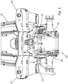
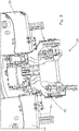
- FIG. 2 and 3 A rear view of the tractor 10 is shown in Figs. 2 and 3 .
- the rear linkage 20 comprises an upper link arm 26 and a pair of lower link arms 28 which project from the body of the tractor 10.
- a quick hitch assembly 30 according to the invention is provided on the rear linkage 20.
- the quick hitch assembly 30 comprises a top link portion 32 and a pair of separate side arm portions 34.
- the top link portion 32 and the side arm portions 34 are coupled together to form the assembled quick hitch 30.
- the top link portion 32 of the quick hitch 30 is arranged to be coupled to the upper link arm 26 of the rear linkage 20, and the side arm portions 34 of the quick hitch 30 are arranged to be coupled to respective lower link arms 28 of the linkage 20.
- An upper hook 36 is provided on the top link portion 32 to present an upper connection point to the quick hitch 30 for a tractor implement.
- lower hooks 38 are provided on the lower, distal ends 34a of the side arm portions 34, to present opposed lower connection points for a tractor implement.
- the lower hooks 38 may be latchably controlled by levers 40 provided on the respective side arm portions 34.
- the side arm portions 34 are arranged to be releasably secured to either side of the top link portion 32.
- the upper ends 34b of the side arm portions 34 may be provided with bolt apertures (not shown). Similar bolt apertures may also be provided in the body of the top link portion 32, such that the side arm portions 34 can be releasably bolted to the top link portion 32, using an array of bolts 42.
- a first set of bolts 42a are arranged to extend from the top link portion 32 to be received in apertures provided on the respective side arm portions 34, while a second set of bolts 42b are arranged to extend from the respective side arm portions 34 to be received in apertures provided on the top link portion 32.
- the respective bolts may then be secured in place, e.g. using suitable threaded nuts and/or internally-threaded apertures, to form the assembled quick hitch 30.
- the assembled quick hitch comprises a generally horizontal upper section, defined by the top link portion 32 and the upper ends 34b of the side arm portions 34, and a pair of generally vertical side sections, defined by the side arm portions 34.
- the lower ends 34a of the side arm portions 34 are preferably arranged to be horizontally offset from the upper ends 34b of the side arm portions 34, such that the assembled quick hitch forms a generally A-shaped frame, with a relatively narrow upper portion.
- Such a construction allows for the ease of use of the quick hitch on a variety of different tractor constructions, in particular for tractor constructions having reduced work space at the rear of the tractor, e.g. due to rearwardly-extending fenders 24.
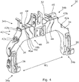
- the quick hitch assembly 30 further comprises a pair of complimentary spacer elements 44.
- the spacer elements 44 are arranged to be selectably located between the top link portion 32 and the respective side arm portions 34 of the assembly 30. Through-going bolt apertures (not shown) are defined in the spacer elements 44.
- the spacer elements 44 can be incorporated into the general quick hitch assembly 30, by passing securing bolts 42 through the apertures in the spacer elements 44, the bolts 42 then secured to the top link portion 32 and/or the respective side arm portions 34 arranged either side of the spacer element 44.
- the top link portion 32 and the upper ends 34b of the side arm portions 34 comprise complementary coupling faces indicated at 46 comprising a first vertical face section 46a, a second vertical face section 46b offset from the first vertical face section 46a, and an angled face section 46c extending between the first and second sections.
- This staggered construction allows for a distribution of forces between the elements of the quick hitch 30.
- the spacer elements 44 are provided as dogleg-shaped elements formed to correspond to the coupling faces of the top link portion 32 and the respective side arm portions 34.
- the spacer elements 42 are arranged between the top link portion 32 and the respective upper ends 34b of the side arm portions 34, such that the assembled quick hitch 30 comprises a hitch width W1 defined between the lower distal ends 34a of the side arm portions 34.
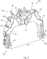
- the spacer elements 42 are not used in the quick hitch construction, such that the side arm portions 34 are directly connected to the top link portion 32 to form a quick hitch having a hitch width W2, W2 being less than W1. It can be seen that the selective use of the spacer elements 42 in the quick hitch assembly allows for the construction of quick hitches having adjustable hitch widths, wherein the spacer elements 42 can be easily incorporated into the overall construction, without the need for time-consuming positioning and alignment methods.
- the quick hitch assembly 30 may be provided with a plurality of spacer elements of different dimensions, allowing for the construction of a wide range of quick hitches having different hitch widths.
- Fig. 5 it can be seen that if the spacer elements 44 are not in use as part of the quick hitch construction, the unused spacer elements 44 may be stored on the assembly itself.
- the spacer elements 44 may be bolted onto the side arm portions 34.
- the side arm portions 34 are provided with a recess to receive the spacer elements 44 when not in use.
- the unused spaced elements 44 can be bolted to the quick hitch assembly 30 using the securing bolts 42 used to secure the side arm portions 34 to the top link portion 32.
- the use of a quick hitch assembly having spacer elements selectably incorporated into the assembled quick hitch provides for an adjustable quick hitch system which is relatively easy to use.
Landscapes
- Life Sciences & Earth Sciences (AREA)
- Zoology (AREA)
- Engineering & Computer Science (AREA)
- Mechanical Engineering (AREA)
- Soil Sciences (AREA)
- Environmental Sciences (AREA)
- Agricultural Machines (AREA)
Claims (12)
- Ensemble d'attelage rapide comprenant :une portion de bielle supérieure (32) ; etune paire de portions de bras de côté (34) à accoupler à la portion de bielle supérieure pour former un attelage rapide assemblé (30),caractérisé en ce que l'ensemble comprend en outre des éléments espaceurs (44) à agencer de façon sélectionnable entre la portion de bielle supérieure (32) et les portions de bras de côté (34), les éléments espaceurs (44) permettant la formation de configurations différentes d'attelage rapide assemblé ayant des dimensions d'attelage rapide différentes.
- Ensemble d'attelage rapide selon la revendication 1, dans lequel une largeur d'attelage rapide est définie entre les extrémités distales (34a) des portions de bras de côté (34) de l'attelage rapide assemblé, dans lequel les éléments espaceurs (44) sont agencés de façon sélectionnable entre la portion de bielle supérieure (32) et les portions de bras de côté (34) pour définir des largeurs d'attelage rapide différentes (W1, W2).
- Ensemble d'attelage rapide selon la revendication 1 ou la revendication 2, dans lequel l'ensemble d'attelage rapide comprend au moins une paire d'éléments espaceurs (44).
- Ensemble d'attelage rapide selon l'une quelconque des revendications 1 à 3, dans lequel l'attelage rapide assemblé (30) comprend une section supérieure généralement horizontale et des sections de côté généralement verticales, dans lequel les portions de bras de côté (34) comprennent chacune une extrémité supérieure (34b) pour un accouplement à la portion de bielle supérieure (32) de l'ensemble et une extrémité inférieure (34a) comprenant un élément de crochet d'attelage, dans lequel l'extrémité inférieure (34a) de la portion de bras de côté est décalée horizontalement de l'extrémité supérieure (34b) de la portion de bras de côté.
- Ensemble d'attelage rapide selon une quelconque revendication précédente, dans lequel les portions de bras de côté (34) sont agencées pour être boulonnées de façon détachable à la portion de bielle supérieure (32), et dans lequel les éléments espaceurs (44) comprennent au moins un orifice de boulon traversant, de sorte que les éléments espaceurs (44) puissent être agencés entre une portion de bras de côté (34) et la portion de bielle supérieure (32), où au moins un boulon d'arrimage (42) est agencé pour s'étendre à travers l'orifice de l'élément espaceur pour arrimer l'élément espaceur (44) entre la portion de bras de côté (34) et la portion de bielle supérieure (32).
- Ensemble d'attelage rapide selon une quelconque revendication précédente, dans lequel la portion de bielle supérieure (32) et les portions de bras de côté (34) comprennent des faces d'accouplement complémentaires comprenant une première section de face verticale (46a), une seconde section de face verticale (46b) décalée de la première section de face verticale, et une section de face en biais (46c) s'étendant entre les première et seconde sections.
- Ensemble d'attelage rapide selon la revendication 6, dans lequel les éléments espaceurs (44) comprennent des éléments de forme coudée formés pour correspondre aux faces d'accouplement de la portion de bielle supérieure (32) et des portions de bras de côté (34) respectives.
- Ensemble d'attelage rapide selon une quelconque revendication précédente, dans lequel les éléments espaceurs (44) sont stockés sur les portions de bras de côté (34) lorsqu'ils ne sont pas en utilisation.
- Ensemble d'attelage rapide selon la revendication 8, dans lequel les éléments espaceurs (44) sont boulonnés de façon détachable sur les portions de bras de côté (34) lorsqu'ils ne sont pas en utilisation.
- Ensemble d'attelage rapide selon la revendication 9, dans lequel les éléments espaceurs (44) sont boulonnés de façon détachable sur au moins l'une des portions de bras de côté (34) par au moins un boulon d'arrimage (42), l'au moins un boulon d'arrimage (42) étant utilisé pour fixer l'au moins une portion de bras de côté (34) à la portion de bielle supérieure (32).
- Ensemble d'attelage rapide selon l'une quelconque des revendications 8 à 10, dans lequel les portions de bras de côté (34) comprennent un évidement formé pour recevoir un élément espaceur (44) lorsque l'élément espaceur n'est pas en utilisation.
- Véhicule agricole (10), de préférence tracteur agricole, ayant un ensemble d'attelage rapide tel que revendiqué à l'une quelconque des revendications 1 à 11.
Applications Claiming Priority (2)
| Application Number | Priority Date | Filing Date | Title |
|---|---|---|---|
| EP14290383 | 2014-12-12 | ||
| PCT/EP2015/079104 WO2016091942A1 (fr) | 2014-12-12 | 2015-12-09 | Ensemble attelage rapide |
Publications (2)
| Publication Number | Publication Date |
|---|---|
| EP3229576A1 EP3229576A1 (fr) | 2017-10-18 |
| EP3229576B1 true EP3229576B1 (fr) | 2018-11-28 |
Family
ID=52144606
Family Applications (1)
| Application Number | Title | Priority Date | Filing Date |
|---|---|---|---|
| EP15807893.1A Active EP3229576B1 (fr) | 2014-12-12 | 2015-12-09 | Ensemble attelage rapide |
Country Status (6)
| Country | Link |
|---|---|
| US (1) | US10462954B2 (fr) |
| EP (1) | EP3229576B1 (fr) |
| CN (1) | CN106998647B (fr) |
| AU (1) | AU2015359458A1 (fr) |
| BR (1) | BR112017010112B1 (fr) |
| WO (1) | WO2016091942A1 (fr) |
Families Citing this family (3)
| Publication number | Priority date | Publication date | Assignee | Title |
|---|---|---|---|---|
| BR112019010351B1 (pt) | 2016-12-09 | 2023-09-26 | Agco International Gmbh | Trator agrícola que tem um sistema de armazenamento de componentes |
| US20240040943A1 (en) * | 2022-08-04 | 2024-02-08 | Deere & Company | Hitching assembly |
| EP4324314A1 (fr) | 2022-08-17 | 2024-02-21 | Agco Corporation | Attelage rapide |
Family Cites Families (14)
| Publication number | Priority date | Publication date | Assignee | Title |
|---|---|---|---|---|
| DE1134235B (de) | 1961-11-15 | 1962-08-02 | John Deere Lanz Ag | Kupplungsvorrichtung zwischen einem Schlepper und einem an diesen anzubauenden Arbeitsgeraet |
| US3231294A (en) * | 1963-01-04 | 1966-01-25 | Deere & Co | Convertible coupler |
| DE1457683A1 (de) | 1965-12-04 | 1969-05-08 | Deere & Co | Kupplungsvorrichtung zum Schnellanschluss von Anbaugeraeten |
| US3829128A (en) | 1972-12-22 | 1974-08-13 | Allis Chalmers | Quick hitch adapter |
| GB8530778D0 (en) * | 1985-12-13 | 1986-01-22 | Metallifacture Ltd | Tractor linkage |
| CA2144137C (fr) * | 1994-03-07 | 2000-08-22 | Harley A. Kravitz | Attelage de remorque reglable en largeur |
| US5582255A (en) * | 1995-03-09 | 1996-12-10 | A.I.L., Inc. | Guidance system having adjustable width capability |
| US6533042B1 (en) | 2000-03-27 | 2003-03-18 | John R. Marine, Sr. | Attachment for tractor |
| US7487843B2 (en) | 2004-10-19 | 2009-02-10 | Cnh America Llc | Adjustable quick hitch |
| US7100936B1 (en) * | 2004-12-13 | 2006-09-05 | Cheng John C | Universal motor vehicle trailer hitch |
| US7849614B2 (en) * | 2007-02-16 | 2010-12-14 | Swisher Acquisition, Inc. | Universal front and rear equipment mount for ATV |
| CN201304872Y (zh) * | 2008-12-10 | 2009-09-09 | 洛阳拖拉机研究所有限公司 | 轮式拖拉机拖挂装置 |
| CN203034505U (zh) * | 2012-11-20 | 2013-07-03 | 山东临工工程机械有限公司 | 新型装载机用快换装置 |
| CN203056512U (zh) * | 2013-02-26 | 2013-07-10 | 火炬电气集团有限公司 | 相间间隔棒 |
-
2015
- 2015-12-09 AU AU2015359458A patent/AU2015359458A1/en not_active Abandoned
- 2015-12-09 EP EP15807893.1A patent/EP3229576B1/fr active Active
- 2015-12-09 WO PCT/EP2015/079104 patent/WO2016091942A1/fr not_active Ceased
- 2015-12-09 CN CN201580067031.1A patent/CN106998647B/zh not_active Expired - Fee Related
- 2015-12-09 US US15/533,066 patent/US10462954B2/en not_active Expired - Fee Related
- 2015-12-09 BR BR112017010112-2A patent/BR112017010112B1/pt not_active IP Right Cessation
Non-Patent Citations (1)
| Title |
|---|
| None * |
Also Published As
| Publication number | Publication date |
|---|---|
| AU2015359458A1 (en) | 2017-06-01 |
| BR112017010112A2 (pt) | 2017-12-26 |
| CN106998647A (zh) | 2017-08-01 |
| US10462954B2 (en) | 2019-11-05 |
| EP3229576A1 (fr) | 2017-10-18 |
| WO2016091942A1 (fr) | 2016-06-16 |
| BR112017010112B1 (pt) | 2021-07-27 |
| CN106998647B (zh) | 2021-02-09 |
| US20180070524A1 (en) | 2018-03-15 |
Similar Documents
| Publication | Publication Date | Title |
|---|---|---|
| EP2759187B1 (fr) | Appareil de traction pour coupler un outil de travail du sol sur un châssis d'instrument agricole | |
| EP2740341A1 (fr) | Appareil de barre d'attelage et engin agricole équipé avec celui-ci | |
| US3306630A (en) | Arrangement for coupling a towed vehicle to a towing vehicle | |
| US8714276B2 (en) | Soil chopping and leveling system | |
| US9137938B2 (en) | Agricultural implement with self-centering pivots | |
| EP3229576B1 (fr) | Ensemble attelage rapide | |
| US4195860A (en) | Offset adapter | |
| US8955238B1 (en) | Adjustable plow blade | |
| US9955621B2 (en) | Front fold implement frame with pivotal draft link connection | |
| US8672048B2 (en) | Tractor pull bar mounting bracket assembly | |
| US9148987B2 (en) | Agricultural caddy and trailer assembly | |
| US5743341A (en) | Toolbar mounting structure providing tool adjustment in the hitch area | |
| EP2653370B1 (fr) | Ensemble châssis semi générique destiné à un véhicule | |
| US4210212A (en) | Tool mounting with member locatable in first and second position between standard and frame | |
| US9139059B1 (en) | Tractor hitch | |
| WO2013151480A1 (fr) | Machine agricole, procédé de fabrication d'une machine pour travailler le sol et outil supplémentaire pour machine agricole | |
| US2907396A (en) | Load transporting attachment for agricultural implements | |
| CN205389345U (zh) | 一种可调节锄草机 | |
| JP2017006082A (ja) | 農作業機 | |
| JP2011155943A (ja) | 農作業機 | |
| US20250133975A1 (en) | Mounting assembly for an agricultural implement | |
| US2092584A (en) | Implement coupling means on tractors | |
| AU2014100705A4 (en) | Improvements to agricultural implements | |
| KR102304887B1 (ko) | 트랙터 엔진 탈거용 지지장치 | |
| EP1763982B1 (fr) | Outil agricole de travail du sol |
Legal Events
| Date | Code | Title | Description |
|---|---|---|---|
| STAA | Information on the status of an ep patent application or granted ep patent |
Free format text: STATUS: THE INTERNATIONAL PUBLICATION HAS BEEN MADE |
|
| PUAI | Public reference made under article 153(3) epc to a published international application that has entered the european phase |
Free format text: ORIGINAL CODE: 0009012 |
|
| STAA | Information on the status of an ep patent application or granted ep patent |
Free format text: STATUS: REQUEST FOR EXAMINATION WAS MADE |
|
| 17P | Request for examination filed |
Effective date: 20170712 |
|
| AK | Designated contracting states |
Kind code of ref document: A1 Designated state(s): AL AT BE BG CH CY CZ DE DK EE ES FI FR GB GR HR HU IE IS IT LI LT LU LV MC MK MT NL NO PL PT RO RS SE SI SK SM TR |
|
| AX | Request for extension of the european patent |
Extension state: BA ME |
|
| DAV | Request for validation of the european patent (deleted) | ||
| DAX | Request for extension of the european patent (deleted) | ||
| GRAP | Despatch of communication of intention to grant a patent |
Free format text: ORIGINAL CODE: EPIDOSNIGR1 |
|
| STAA | Information on the status of an ep patent application or granted ep patent |
Free format text: STATUS: GRANT OF PATENT IS INTENDED |
|
| INTG | Intention to grant announced |
Effective date: 20180620 |
|
| GRAS | Grant fee paid |
Free format text: ORIGINAL CODE: EPIDOSNIGR3 |
|
| GRAA | (expected) grant |
Free format text: ORIGINAL CODE: 0009210 |
|
| STAA | Information on the status of an ep patent application or granted ep patent |
Free format text: STATUS: THE PATENT HAS BEEN GRANTED |
|
| AK | Designated contracting states |
Kind code of ref document: B1 Designated state(s): AL AT BE BG CH CY CZ DE DK EE ES FI FR GB GR HR HU IE IS IT LI LT LU LV MC MK MT NL NO PL PT RO RS SE SI SK SM TR |
|
| REG | Reference to a national code |
Ref country code: CH Ref legal event code: EP |
|
| REG | Reference to a national code |
Ref country code: AT Ref legal event code: REF Ref document number: 1069118 Country of ref document: AT Kind code of ref document: T Effective date: 20181215 |
|
| REG | Reference to a national code |
Ref country code: DE Ref legal event code: R096 Ref document number: 602015020590 Country of ref document: DE |
|
| REG | Reference to a national code |
Ref country code: IE Ref legal event code: FG4D |
|
| REG | Reference to a national code |
Ref country code: NL Ref legal event code: MP Effective date: 20181128 |
|
| REG | Reference to a national code |
Ref country code: LT Ref legal event code: MG4D |
|
| REG | Reference to a national code |
Ref country code: AT Ref legal event code: MK05 Ref document number: 1069118 Country of ref document: AT Kind code of ref document: T Effective date: 20181128 |
|
| PG25 | Lapsed in a contracting state [announced via postgrant information from national office to epo] |
Ref country code: IS Free format text: LAPSE BECAUSE OF FAILURE TO SUBMIT A TRANSLATION OF THE DESCRIPTION OR TO PAY THE FEE WITHIN THE PRESCRIBED TIME-LIMIT Effective date: 20190328 Ref country code: AT Free format text: LAPSE BECAUSE OF FAILURE TO SUBMIT A TRANSLATION OF THE DESCRIPTION OR TO PAY THE FEE WITHIN THE PRESCRIBED TIME-LIMIT Effective date: 20181128 Ref country code: HR Free format text: LAPSE BECAUSE OF FAILURE TO SUBMIT A TRANSLATION OF THE DESCRIPTION OR TO PAY THE FEE WITHIN THE PRESCRIBED TIME-LIMIT Effective date: 20181128 Ref country code: NO Free format text: LAPSE BECAUSE OF FAILURE TO SUBMIT A TRANSLATION OF THE DESCRIPTION OR TO PAY THE FEE WITHIN THE PRESCRIBED TIME-LIMIT Effective date: 20190228 Ref country code: LT Free format text: LAPSE BECAUSE OF FAILURE TO SUBMIT A TRANSLATION OF THE DESCRIPTION OR TO PAY THE FEE WITHIN THE PRESCRIBED TIME-LIMIT Effective date: 20181128 Ref country code: FI Free format text: LAPSE BECAUSE OF FAILURE TO SUBMIT A TRANSLATION OF THE DESCRIPTION OR TO PAY THE FEE WITHIN THE PRESCRIBED TIME-LIMIT Effective date: 20181128 Ref country code: ES Free format text: LAPSE BECAUSE OF FAILURE TO SUBMIT A TRANSLATION OF THE DESCRIPTION OR TO PAY THE FEE WITHIN THE PRESCRIBED TIME-LIMIT Effective date: 20181128 Ref country code: BG Free format text: LAPSE BECAUSE OF FAILURE TO SUBMIT A TRANSLATION OF THE DESCRIPTION OR TO PAY THE FEE WITHIN THE PRESCRIBED TIME-LIMIT Effective date: 20190228 Ref country code: LV Free format text: LAPSE BECAUSE OF FAILURE TO SUBMIT A TRANSLATION OF THE DESCRIPTION OR TO PAY THE FEE WITHIN THE PRESCRIBED TIME-LIMIT Effective date: 20181128 |
|
| PG25 | Lapsed in a contracting state [announced via postgrant information from national office to epo] |
Ref country code: AL Free format text: LAPSE BECAUSE OF FAILURE TO SUBMIT A TRANSLATION OF THE DESCRIPTION OR TO PAY THE FEE WITHIN THE PRESCRIBED TIME-LIMIT Effective date: 20181128 Ref country code: PT Free format text: LAPSE BECAUSE OF FAILURE TO SUBMIT A TRANSLATION OF THE DESCRIPTION OR TO PAY THE FEE WITHIN THE PRESCRIBED TIME-LIMIT Effective date: 20190328 Ref country code: SE Free format text: LAPSE BECAUSE OF FAILURE TO SUBMIT A TRANSLATION OF THE DESCRIPTION OR TO PAY THE FEE WITHIN THE PRESCRIBED TIME-LIMIT Effective date: 20181128 Ref country code: RS Free format text: LAPSE BECAUSE OF FAILURE TO SUBMIT A TRANSLATION OF THE DESCRIPTION OR TO PAY THE FEE WITHIN THE PRESCRIBED TIME-LIMIT Effective date: 20181128 Ref country code: GR Free format text: LAPSE BECAUSE OF FAILURE TO SUBMIT A TRANSLATION OF THE DESCRIPTION OR TO PAY THE FEE WITHIN THE PRESCRIBED TIME-LIMIT Effective date: 20190301 |
|
| PG25 | Lapsed in a contracting state [announced via postgrant information from national office to epo] |
Ref country code: NL Free format text: LAPSE BECAUSE OF FAILURE TO SUBMIT A TRANSLATION OF THE DESCRIPTION OR TO PAY THE FEE WITHIN THE PRESCRIBED TIME-LIMIT Effective date: 20181128 |
|
| PG25 | Lapsed in a contracting state [announced via postgrant information from national office to epo] |
Ref country code: CZ Free format text: LAPSE BECAUSE OF FAILURE TO SUBMIT A TRANSLATION OF THE DESCRIPTION OR TO PAY THE FEE WITHIN THE PRESCRIBED TIME-LIMIT Effective date: 20181128 Ref country code: PL Free format text: LAPSE BECAUSE OF FAILURE TO SUBMIT A TRANSLATION OF THE DESCRIPTION OR TO PAY THE FEE WITHIN THE PRESCRIBED TIME-LIMIT Effective date: 20181128 Ref country code: DK Free format text: LAPSE BECAUSE OF FAILURE TO SUBMIT A TRANSLATION OF THE DESCRIPTION OR TO PAY THE FEE WITHIN THE PRESCRIBED TIME-LIMIT Effective date: 20181128 |
|
| REG | Reference to a national code |
Ref country code: CH Ref legal event code: PL |
|
| REG | Reference to a national code |
Ref country code: DE Ref legal event code: R097 Ref document number: 602015020590 Country of ref document: DE |
|
| PG25 | Lapsed in a contracting state [announced via postgrant information from national office to epo] |
Ref country code: SM Free format text: LAPSE BECAUSE OF FAILURE TO SUBMIT A TRANSLATION OF THE DESCRIPTION OR TO PAY THE FEE WITHIN THE PRESCRIBED TIME-LIMIT Effective date: 20181128 Ref country code: EE Free format text: LAPSE BECAUSE OF FAILURE TO SUBMIT A TRANSLATION OF THE DESCRIPTION OR TO PAY THE FEE WITHIN THE PRESCRIBED TIME-LIMIT Effective date: 20181128 Ref country code: RO Free format text: LAPSE BECAUSE OF FAILURE TO SUBMIT A TRANSLATION OF THE DESCRIPTION OR TO PAY THE FEE WITHIN THE PRESCRIBED TIME-LIMIT Effective date: 20181128 Ref country code: SK Free format text: LAPSE BECAUSE OF FAILURE TO SUBMIT A TRANSLATION OF THE DESCRIPTION OR TO PAY THE FEE WITHIN THE PRESCRIBED TIME-LIMIT Effective date: 20181128 Ref country code: MC Free format text: LAPSE BECAUSE OF FAILURE TO SUBMIT A TRANSLATION OF THE DESCRIPTION OR TO PAY THE FEE WITHIN THE PRESCRIBED TIME-LIMIT Effective date: 20181128 Ref country code: LU Free format text: LAPSE BECAUSE OF NON-PAYMENT OF DUE FEES Effective date: 20181209 |
|
| REG | Reference to a national code |
Ref country code: IE Ref legal event code: MM4A |
|
| REG | Reference to a national code |
Ref country code: BE Ref legal event code: MM Effective date: 20181231 |
|
| PLBE | No opposition filed within time limit |
Free format text: ORIGINAL CODE: 0009261 |
|
| STAA | Information on the status of an ep patent application or granted ep patent |
Free format text: STATUS: NO OPPOSITION FILED WITHIN TIME LIMIT |
|
| PG25 | Lapsed in a contracting state [announced via postgrant information from national office to epo] |
Ref country code: IE Free format text: LAPSE BECAUSE OF NON-PAYMENT OF DUE FEES Effective date: 20181209 Ref country code: SI Free format text: LAPSE BECAUSE OF FAILURE TO SUBMIT A TRANSLATION OF THE DESCRIPTION OR TO PAY THE FEE WITHIN THE PRESCRIBED TIME-LIMIT Effective date: 20181128 |
|
| 26N | No opposition filed |
Effective date: 20190829 |
|
| PG25 | Lapsed in a contracting state [announced via postgrant information from national office to epo] |
Ref country code: BE Free format text: LAPSE BECAUSE OF NON-PAYMENT OF DUE FEES Effective date: 20181231 |
|
| PG25 | Lapsed in a contracting state [announced via postgrant information from national office to epo] |
Ref country code: LI Free format text: LAPSE BECAUSE OF NON-PAYMENT OF DUE FEES Effective date: 20181231 Ref country code: CH Free format text: LAPSE BECAUSE OF NON-PAYMENT OF DUE FEES Effective date: 20181231 |
|
| PG25 | Lapsed in a contracting state [announced via postgrant information from national office to epo] |
Ref country code: MT Free format text: LAPSE BECAUSE OF NON-PAYMENT OF DUE FEES Effective date: 20181209 |
|
| PG25 | Lapsed in a contracting state [announced via postgrant information from national office to epo] |
Ref country code: TR Free format text: LAPSE BECAUSE OF FAILURE TO SUBMIT A TRANSLATION OF THE DESCRIPTION OR TO PAY THE FEE WITHIN THE PRESCRIBED TIME-LIMIT Effective date: 20181128 |
|
| PG25 | Lapsed in a contracting state [announced via postgrant information from national office to epo] |
Ref country code: MK Free format text: LAPSE BECAUSE OF NON-PAYMENT OF DUE FEES Effective date: 20181128 Ref country code: HU Free format text: LAPSE BECAUSE OF FAILURE TO SUBMIT A TRANSLATION OF THE DESCRIPTION OR TO PAY THE FEE WITHIN THE PRESCRIBED TIME-LIMIT; INVALID AB INITIO Effective date: 20151209 Ref country code: CY Free format text: LAPSE BECAUSE OF FAILURE TO SUBMIT A TRANSLATION OF THE DESCRIPTION OR TO PAY THE FEE WITHIN THE PRESCRIBED TIME-LIMIT Effective date: 20181128 |
|
| PGFP | Annual fee paid to national office [announced via postgrant information from national office to epo] |
Ref country code: GB Payment date: 20211222 Year of fee payment: 7 |
|
| PGFP | Annual fee paid to national office [announced via postgrant information from national office to epo] |
Ref country code: IT Payment date: 20211222 Year of fee payment: 7 |
|
| REG | Reference to a national code |
Ref country code: DE Ref legal event code: R084 Ref document number: 602015020590 Country of ref document: DE |
|
| P01 | Opt-out of the competence of the unified patent court (upc) registered |
Effective date: 20230518 |
|
| GBPC | Gb: european patent ceased through non-payment of renewal fee |
Effective date: 20221209 |
|
| PG25 | Lapsed in a contracting state [announced via postgrant information from national office to epo] |
Ref country code: GB Free format text: LAPSE BECAUSE OF NON-PAYMENT OF DUE FEES Effective date: 20221209 |
|
| PG25 | Lapsed in a contracting state [announced via postgrant information from national office to epo] |
Ref country code: IT Free format text: LAPSE BECAUSE OF NON-PAYMENT OF DUE FEES Effective date: 20221209 |
|
| PGFP | Annual fee paid to national office [announced via postgrant information from national office to epo] |
Ref country code: DE Payment date: 20241210 Year of fee payment: 10 |
|
| PGFP | Annual fee paid to national office [announced via postgrant information from national office to epo] |
Ref country code: FR Payment date: 20241224 Year of fee payment: 10 |