EP3231585B1 - Dispositif de soudage par ultrasons - Google Patents
Dispositif de soudage par ultrasons Download PDFInfo
- Publication number
- EP3231585B1 EP3231585B1 EP17000493.1A EP17000493A EP3231585B1 EP 3231585 B1 EP3231585 B1 EP 3231585B1 EP 17000493 A EP17000493 A EP 17000493A EP 3231585 B1 EP3231585 B1 EP 3231585B1
- Authority
- EP
- European Patent Office
- Prior art keywords
- ultrasonic
- welding
- ultrasonic welding
- length
- welding unit
- Prior art date
- Legal status (The legal status is an assumption and is not a legal conclusion. Google has not performed a legal analysis and makes no representation as to the accuracy of the status listed.)
- Active
Links
Images



Classifications
-
- B—PERFORMING OPERATIONS; TRANSPORTING
- B29—WORKING OF PLASTICS; WORKING OF SUBSTANCES IN A PLASTIC STATE IN GENERAL
- B29C—SHAPING OR JOINING OF PLASTICS; SHAPING OF MATERIAL IN A PLASTIC STATE, NOT OTHERWISE PROVIDED FOR; AFTER-TREATMENT OF THE SHAPED PRODUCTS, e.g. REPAIRING
- B29C65/00—Joining or sealing of preformed parts, e.g. welding of plastics materials; Apparatus therefor
- B29C65/02—Joining or sealing of preformed parts, e.g. welding of plastics materials; Apparatus therefor by heating, with or without pressure
- B29C65/08—Joining or sealing of preformed parts, e.g. welding of plastics materials; Apparatus therefor by heating, with or without pressure using ultrasonic vibrations
-
- B—PERFORMING OPERATIONS; TRANSPORTING
- B29—WORKING OF PLASTICS; WORKING OF SUBSTANCES IN A PLASTIC STATE IN GENERAL
- B29C—SHAPING OR JOINING OF PLASTICS; SHAPING OF MATERIAL IN A PLASTIC STATE, NOT OTHERWISE PROVIDED FOR; AFTER-TREATMENT OF THE SHAPED PRODUCTS, e.g. REPAIRING
- B29C66/00—General aspects of processes or apparatus for joining preformed parts
- B29C66/01—General aspects dealing with the joint area or with the area to be joined
- B29C66/05—Particular design of joint configurations
- B29C66/10—Particular design of joint configurations particular design of the joint cross-sections
- B29C66/11—Joint cross-sections comprising a single joint-segment, i.e. one of the parts to be joined comprising a single joint-segment in the joint cross-section
- B29C66/112—Single lapped joints
- B29C66/1122—Single lap to lap joints, i.e. overlap joints
-
- B—PERFORMING OPERATIONS; TRANSPORTING
- B29—WORKING OF PLASTICS; WORKING OF SUBSTANCES IN A PLASTIC STATE IN GENERAL
- B29C—SHAPING OR JOINING OF PLASTICS; SHAPING OF MATERIAL IN A PLASTIC STATE, NOT OTHERWISE PROVIDED FOR; AFTER-TREATMENT OF THE SHAPED PRODUCTS, e.g. REPAIRING
- B29C66/00—General aspects of processes or apparatus for joining preformed parts
- B29C66/40—General aspects of joining substantially flat articles, e.g. plates, sheets or web-like materials; Making flat seams in tubular or hollow articles; Joining single elements to substantially flat surfaces
- B29C66/41—Joining substantially flat articles ; Making flat seams in tubular or hollow articles
- B29C66/43—Joining a relatively small portion of the surface of said articles
- B29C66/431—Joining the articles to themselves
-
- B—PERFORMING OPERATIONS; TRANSPORTING
- B29—WORKING OF PLASTICS; WORKING OF SUBSTANCES IN A PLASTIC STATE IN GENERAL
- B29C—SHAPING OR JOINING OF PLASTICS; SHAPING OF MATERIAL IN A PLASTIC STATE, NOT OTHERWISE PROVIDED FOR; AFTER-TREATMENT OF THE SHAPED PRODUCTS, e.g. REPAIRING
- B29C66/00—General aspects of processes or apparatus for joining preformed parts
- B29C66/80—General aspects of machine operations or constructions and parts thereof
- B29C66/81—General aspects of the pressing elements, i.e. the elements applying pressure on the parts to be joined in the area to be joined, e.g. the welding jaws or clamps
- B29C66/816—General aspects of the pressing elements, i.e. the elements applying pressure on the parts to be joined in the area to be joined, e.g. the welding jaws or clamps characterised by the mounting of the pressing elements, e.g. of the welding jaws or clamps
- B29C66/8163—Self-aligning to the joining plane, e.g. mounted on a ball and socket
-
- B—PERFORMING OPERATIONS; TRANSPORTING
- B29—WORKING OF PLASTICS; WORKING OF SUBSTANCES IN A PLASTIC STATE IN GENERAL
- B29C—SHAPING OR JOINING OF PLASTICS; SHAPING OF MATERIAL IN A PLASTIC STATE, NOT OTHERWISE PROVIDED FOR; AFTER-TREATMENT OF THE SHAPED PRODUCTS, e.g. REPAIRING
- B29C66/00—General aspects of processes or apparatus for joining preformed parts
- B29C66/80—General aspects of machine operations or constructions and parts thereof
- B29C66/81—General aspects of the pressing elements, i.e. the elements applying pressure on the parts to be joined in the area to be joined, e.g. the welding jaws or clamps
- B29C66/816—General aspects of the pressing elements, i.e. the elements applying pressure on the parts to be joined in the area to be joined, e.g. the welding jaws or clamps characterised by the mounting of the pressing elements, e.g. of the welding jaws or clamps
- B29C66/8167—Quick change joining tools or surfaces
-
- B—PERFORMING OPERATIONS; TRANSPORTING
- B29—WORKING OF PLASTICS; WORKING OF SUBSTANCES IN A PLASTIC STATE IN GENERAL
- B29C—SHAPING OR JOINING OF PLASTICS; SHAPING OF MATERIAL IN A PLASTIC STATE, NOT OTHERWISE PROVIDED FOR; AFTER-TREATMENT OF THE SHAPED PRODUCTS, e.g. REPAIRING
- B29C66/00—General aspects of processes or apparatus for joining preformed parts
- B29C66/80—General aspects of machine operations or constructions and parts thereof
- B29C66/81—General aspects of the pressing elements, i.e. the elements applying pressure on the parts to be joined in the area to be joined, e.g. the welding jaws or clamps
- B29C66/818—General aspects of the pressing elements, i.e. the elements applying pressure on the parts to be joined in the area to be joined, e.g. the welding jaws or clamps characterised by the cooling constructional aspects, or by the thermal or electrical insulating or conducting constructional aspects of the welding jaws or of the clamps ; comprising means for compensating for the thermal expansion of the welding jaws or of the clamps
- B29C66/8181—General aspects of the pressing elements, i.e. the elements applying pressure on the parts to be joined in the area to be joined, e.g. the welding jaws or clamps characterised by the cooling constructional aspects, or by the thermal or electrical insulating or conducting constructional aspects of the welding jaws or of the clamps ; comprising means for compensating for the thermal expansion of the welding jaws or of the clamps characterised by the cooling constructional aspects
- B29C66/81811—General aspects of the pressing elements, i.e. the elements applying pressure on the parts to be joined in the area to be joined, e.g. the welding jaws or clamps characterised by the cooling constructional aspects, or by the thermal or electrical insulating or conducting constructional aspects of the welding jaws or of the clamps ; comprising means for compensating for the thermal expansion of the welding jaws or of the clamps characterised by the cooling constructional aspects of the welding jaws
-
- B—PERFORMING OPERATIONS; TRANSPORTING
- B29—WORKING OF PLASTICS; WORKING OF SUBSTANCES IN A PLASTIC STATE IN GENERAL
- B29C—SHAPING OR JOINING OF PLASTICS; SHAPING OF MATERIAL IN A PLASTIC STATE, NOT OTHERWISE PROVIDED FOR; AFTER-TREATMENT OF THE SHAPED PRODUCTS, e.g. REPAIRING
- B29C66/00—General aspects of processes or apparatus for joining preformed parts
- B29C66/80—General aspects of machine operations or constructions and parts thereof
- B29C66/81—General aspects of the pressing elements, i.e. the elements applying pressure on the parts to be joined in the area to be joined, e.g. the welding jaws or clamps
- B29C66/818—General aspects of the pressing elements, i.e. the elements applying pressure on the parts to be joined in the area to be joined, e.g. the welding jaws or clamps characterised by the cooling constructional aspects, or by the thermal or electrical insulating or conducting constructional aspects of the welding jaws or of the clamps ; comprising means for compensating for the thermal expansion of the welding jaws or of the clamps
- B29C66/8181—General aspects of the pressing elements, i.e. the elements applying pressure on the parts to be joined in the area to be joined, e.g. the welding jaws or clamps characterised by the cooling constructional aspects, or by the thermal or electrical insulating or conducting constructional aspects of the welding jaws or of the clamps ; comprising means for compensating for the thermal expansion of the welding jaws or of the clamps characterised by the cooling constructional aspects
- B29C66/81811—General aspects of the pressing elements, i.e. the elements applying pressure on the parts to be joined in the area to be joined, e.g. the welding jaws or clamps characterised by the cooling constructional aspects, or by the thermal or electrical insulating or conducting constructional aspects of the welding jaws or of the clamps ; comprising means for compensating for the thermal expansion of the welding jaws or of the clamps characterised by the cooling constructional aspects of the welding jaws
- B29C66/81812—General aspects of the pressing elements, i.e. the elements applying pressure on the parts to be joined in the area to be joined, e.g. the welding jaws or clamps characterised by the cooling constructional aspects, or by the thermal or electrical insulating or conducting constructional aspects of the welding jaws or of the clamps ; comprising means for compensating for the thermal expansion of the welding jaws or of the clamps characterised by the cooling constructional aspects of the welding jaws the welding jaws being cooled from the outside, e.g. by blowing a gas or spraying a liquid
-
- B—PERFORMING OPERATIONS; TRANSPORTING
- B29—WORKING OF PLASTICS; WORKING OF SUBSTANCES IN A PLASTIC STATE IN GENERAL
- B29C—SHAPING OR JOINING OF PLASTICS; SHAPING OF MATERIAL IN A PLASTIC STATE, NOT OTHERWISE PROVIDED FOR; AFTER-TREATMENT OF THE SHAPED PRODUCTS, e.g. REPAIRING
- B29C66/00—General aspects of processes or apparatus for joining preformed parts
- B29C66/80—General aspects of machine operations or constructions and parts thereof
- B29C66/82—Pressure application arrangements, e.g. transmission or actuating mechanisms for joining tools or clamps
- B29C66/822—Transmission mechanisms
- B29C66/8226—Cam mechanisms; Wedges; Eccentric mechanisms
- B29C66/82265—Eccentric mechanisms
-
- B—PERFORMING OPERATIONS; TRANSPORTING
- B29—WORKING OF PLASTICS; WORKING OF SUBSTANCES IN A PLASTIC STATE IN GENERAL
- B29C—SHAPING OR JOINING OF PLASTICS; SHAPING OF MATERIAL IN A PLASTIC STATE, NOT OTHERWISE PROVIDED FOR; AFTER-TREATMENT OF THE SHAPED PRODUCTS, e.g. REPAIRING
- B29C66/00—General aspects of processes or apparatus for joining preformed parts
- B29C66/80—General aspects of machine operations or constructions and parts thereof
- B29C66/82—Pressure application arrangements, e.g. transmission or actuating mechanisms for joining tools or clamps
- B29C66/824—Actuating mechanisms
- B29C66/8242—Pneumatic or hydraulic drives
- B29C66/82421—Pneumatic or hydraulic drives using an inflatable element positioned between the joining tool and a backing-up part
-
- B—PERFORMING OPERATIONS; TRANSPORTING
- B29—WORKING OF PLASTICS; WORKING OF SUBSTANCES IN A PLASTIC STATE IN GENERAL
- B29C—SHAPING OR JOINING OF PLASTICS; SHAPING OF MATERIAL IN A PLASTIC STATE, NOT OTHERWISE PROVIDED FOR; AFTER-TREATMENT OF THE SHAPED PRODUCTS, e.g. REPAIRING
- B29C66/00—General aspects of processes or apparatus for joining preformed parts
- B29C66/80—General aspects of machine operations or constructions and parts thereof
- B29C66/83—General aspects of machine operations or constructions and parts thereof characterised by the movement of the joining or pressing tools
- B29C66/832—Reciprocating joining or pressing tools
- B29C66/8322—Joining or pressing tools reciprocating along one axis
-
- B—PERFORMING OPERATIONS; TRANSPORTING
- B29—WORKING OF PLASTICS; WORKING OF SUBSTANCES IN A PLASTIC STATE IN GENERAL
- B29C—SHAPING OR JOINING OF PLASTICS; SHAPING OF MATERIAL IN A PLASTIC STATE, NOT OTHERWISE PROVIDED FOR; AFTER-TREATMENT OF THE SHAPED PRODUCTS, e.g. REPAIRING
- B29C66/00—General aspects of processes or apparatus for joining preformed parts
- B29C66/80—General aspects of machine operations or constructions and parts thereof
- B29C66/83—General aspects of machine operations or constructions and parts thereof characterised by the movement of the joining or pressing tools
- B29C66/832—Reciprocating joining or pressing tools
- B29C66/8322—Joining or pressing tools reciprocating along one axis
- B29C66/83221—Joining or pressing tools reciprocating along one axis cooperating reciprocating tools, each tool reciprocating along one axis
-
- B—PERFORMING OPERATIONS; TRANSPORTING
- B29—WORKING OF PLASTICS; WORKING OF SUBSTANCES IN A PLASTIC STATE IN GENERAL
- B29C—SHAPING OR JOINING OF PLASTICS; SHAPING OF MATERIAL IN A PLASTIC STATE, NOT OTHERWISE PROVIDED FOR; AFTER-TREATMENT OF THE SHAPED PRODUCTS, e.g. REPAIRING
- B29C66/00—General aspects of processes or apparatus for joining preformed parts
- B29C66/80—General aspects of machine operations or constructions and parts thereof
- B29C66/84—Specific machine types or machines suitable for specific applications
- B29C66/845—C-clamp type or sewing machine type
-
- B—PERFORMING OPERATIONS; TRANSPORTING
- B29—WORKING OF PLASTICS; WORKING OF SUBSTANCES IN A PLASTIC STATE IN GENERAL
- B29C—SHAPING OR JOINING OF PLASTICS; SHAPING OF MATERIAL IN A PLASTIC STATE, NOT OTHERWISE PROVIDED FOR; AFTER-TREATMENT OF THE SHAPED PRODUCTS, e.g. REPAIRING
- B29C66/00—General aspects of processes or apparatus for joining preformed parts
- B29C66/80—General aspects of machine operations or constructions and parts thereof
- B29C66/84—Specific machine types or machines suitable for specific applications
- B29C66/851—Bag or container making machines
- B29C66/8511—Bag making machines
-
- B—PERFORMING OPERATIONS; TRANSPORTING
- B29—WORKING OF PLASTICS; WORKING OF SUBSTANCES IN A PLASTIC STATE IN GENERAL
- B29C—SHAPING OR JOINING OF PLASTICS; SHAPING OF MATERIAL IN A PLASTIC STATE, NOT OTHERWISE PROVIDED FOR; AFTER-TREATMENT OF THE SHAPED PRODUCTS, e.g. REPAIRING
- B29C66/00—General aspects of processes or apparatus for joining preformed parts
- B29C66/80—General aspects of machine operations or constructions and parts thereof
- B29C66/87—Auxiliary operations or devices
- B29C66/876—Maintenance or cleaning
- B29C66/8762—Cleaning of the joining tools
-
- B—PERFORMING OPERATIONS; TRANSPORTING
- B29—WORKING OF PLASTICS; WORKING OF SUBSTANCES IN A PLASTIC STATE IN GENERAL
- B29C—SHAPING OR JOINING OF PLASTICS; SHAPING OF MATERIAL IN A PLASTIC STATE, NOT OTHERWISE PROVIDED FOR; AFTER-TREATMENT OF THE SHAPED PRODUCTS, e.g. REPAIRING
- B29C66/00—General aspects of processes or apparatus for joining preformed parts
- B29C66/90—Measuring or controlling the joining process
- B29C66/92—Measuring or controlling the joining process by measuring or controlling the pressure, the force, the mechanical power or the displacement of the joining tools
- B29C66/924—Measuring or controlling the joining process by measuring or controlling the pressure, the force, the mechanical power or the displacement of the joining tools by controlling or regulating the pressure, the force, the mechanical power or the displacement of the joining tools
- B29C66/9241—Measuring or controlling the joining process by measuring or controlling the pressure, the force, the mechanical power or the displacement of the joining tools by controlling or regulating the pressure, the force, the mechanical power or the displacement of the joining tools by controlling or regulating the pressure, the force or the mechanical power
- B29C66/92431—Measuring or controlling the joining process by measuring or controlling the pressure, the force, the mechanical power or the displacement of the joining tools by controlling or regulating the pressure, the force, the mechanical power or the displacement of the joining tools by controlling or regulating the pressure, the force or the mechanical power the pressure, the force or the mechanical power being kept constant over time
-
- B—PERFORMING OPERATIONS; TRANSPORTING
- B29—WORKING OF PLASTICS; WORKING OF SUBSTANCES IN A PLASTIC STATE IN GENERAL
- B29C—SHAPING OR JOINING OF PLASTICS; SHAPING OF MATERIAL IN A PLASTIC STATE, NOT OTHERWISE PROVIDED FOR; AFTER-TREATMENT OF THE SHAPED PRODUCTS, e.g. REPAIRING
- B29C66/00—General aspects of processes or apparatus for joining preformed parts
- B29C66/90—Measuring or controlling the joining process
- B29C66/92—Measuring or controlling the joining process by measuring or controlling the pressure, the force, the mechanical power or the displacement of the joining tools
- B29C66/924—Measuring or controlling the joining process by measuring or controlling the pressure, the force, the mechanical power or the displacement of the joining tools by controlling or regulating the pressure, the force, the mechanical power or the displacement of the joining tools
- B29C66/9241—Measuring or controlling the joining process by measuring or controlling the pressure, the force, the mechanical power or the displacement of the joining tools by controlling or regulating the pressure, the force, the mechanical power or the displacement of the joining tools by controlling or regulating the pressure, the force or the mechanical power
- B29C66/92441—Measuring or controlling the joining process by measuring or controlling the pressure, the force, the mechanical power or the displacement of the joining tools by controlling or regulating the pressure, the force, the mechanical power or the displacement of the joining tools by controlling or regulating the pressure, the force or the mechanical power the pressure, the force or the mechanical power being non-constant over time
-
- B—PERFORMING OPERATIONS; TRANSPORTING
- B29—WORKING OF PLASTICS; WORKING OF SUBSTANCES IN A PLASTIC STATE IN GENERAL
- B29C—SHAPING OR JOINING OF PLASTICS; SHAPING OF MATERIAL IN A PLASTIC STATE, NOT OTHERWISE PROVIDED FOR; AFTER-TREATMENT OF THE SHAPED PRODUCTS, e.g. REPAIRING
- B29C66/00—General aspects of processes or apparatus for joining preformed parts
- B29C66/80—General aspects of machine operations or constructions and parts thereof
- B29C66/81—General aspects of the pressing elements, i.e. the elements applying pressure on the parts to be joined in the area to be joined, e.g. the welding jaws or clamps
- B29C66/816—General aspects of the pressing elements, i.e. the elements applying pressure on the parts to be joined in the area to be joined, e.g. the welding jaws or clamps characterised by the mounting of the pressing elements, e.g. of the welding jaws or clamps
- B29C66/8161—General aspects of the pressing elements, i.e. the elements applying pressure on the parts to be joined in the area to be joined, e.g. the welding jaws or clamps characterised by the mounting of the pressing elements, e.g. of the welding jaws or clamps said pressing elements being supported or backed-up by springs or by resilient material
-
- B—PERFORMING OPERATIONS; TRANSPORTING
- B29—WORKING OF PLASTICS; WORKING OF SUBSTANCES IN A PLASTIC STATE IN GENERAL
- B29C—SHAPING OR JOINING OF PLASTICS; SHAPING OF MATERIAL IN A PLASTIC STATE, NOT OTHERWISE PROVIDED FOR; AFTER-TREATMENT OF THE SHAPED PRODUCTS, e.g. REPAIRING
- B29C66/00—General aspects of processes or apparatus for joining preformed parts
- B29C66/80—General aspects of machine operations or constructions and parts thereof
- B29C66/82—Pressure application arrangements, e.g. transmission or actuating mechanisms for joining tools or clamps
- B29C66/824—Actuating mechanisms
- B29C66/8242—Pneumatic or hydraulic drives
-
- B—PERFORMING OPERATIONS; TRANSPORTING
- B29—WORKING OF PLASTICS; WORKING OF SUBSTANCES IN A PLASTIC STATE IN GENERAL
- B29C—SHAPING OR JOINING OF PLASTICS; SHAPING OF MATERIAL IN A PLASTIC STATE, NOT OTHERWISE PROVIDED FOR; AFTER-TREATMENT OF THE SHAPED PRODUCTS, e.g. REPAIRING
- B29C66/00—General aspects of processes or apparatus for joining preformed parts
- B29C66/90—Measuring or controlling the joining process
- B29C66/92—Measuring or controlling the joining process by measuring or controlling the pressure, the force, the mechanical power or the displacement of the joining tools
- B29C66/922—Measuring or controlling the joining process by measuring or controlling the pressure, the force, the mechanical power or the displacement of the joining tools by measuring the pressure, the force, the mechanical power or the displacement of the joining tools
- B29C66/9221—Measuring or controlling the joining process by measuring or controlling the pressure, the force, the mechanical power or the displacement of the joining tools by measuring the pressure, the force, the mechanical power or the displacement of the joining tools by measuring the pressure, the force or the mechanical power
-
- B—PERFORMING OPERATIONS; TRANSPORTING
- B29—WORKING OF PLASTICS; WORKING OF SUBSTANCES IN A PLASTIC STATE IN GENERAL
- B29C—SHAPING OR JOINING OF PLASTICS; SHAPING OF MATERIAL IN A PLASTIC STATE, NOT OTHERWISE PROVIDED FOR; AFTER-TREATMENT OF THE SHAPED PRODUCTS, e.g. REPAIRING
- B29C66/00—General aspects of processes or apparatus for joining preformed parts
- B29C66/90—Measuring or controlling the joining process
- B29C66/92—Measuring or controlling the joining process by measuring or controlling the pressure, the force, the mechanical power or the displacement of the joining tools
- B29C66/924—Measuring or controlling the joining process by measuring or controlling the pressure, the force, the mechanical power or the displacement of the joining tools by controlling or regulating the pressure, the force, the mechanical power or the displacement of the joining tools
- B29C66/9241—Measuring or controlling the joining process by measuring or controlling the pressure, the force, the mechanical power or the displacement of the joining tools by controlling or regulating the pressure, the force, the mechanical power or the displacement of the joining tools by controlling or regulating the pressure, the force or the mechanical power
- B29C66/92441—Measuring or controlling the joining process by measuring or controlling the pressure, the force, the mechanical power or the displacement of the joining tools by controlling or regulating the pressure, the force, the mechanical power or the displacement of the joining tools by controlling or regulating the pressure, the force or the mechanical power the pressure, the force or the mechanical power being non-constant over time
- B29C66/92443—Measuring or controlling the joining process by measuring or controlling the pressure, the force, the mechanical power or the displacement of the joining tools by controlling or regulating the pressure, the force, the mechanical power or the displacement of the joining tools by controlling or regulating the pressure, the force or the mechanical power the pressure, the force or the mechanical power being non-constant over time following a pressure-time profile
Definitions
- the present invention relates to a device for ultrasonic welding of materials, in particular foils, with an ultrasonic welding unit having an ultrasonic sonotrode.
- the DE 10 2011 006 932 B4 suggests that the counter tool be adjusted if necessary by means of a linear motor and thus increase the contact pressure if necessary.
- the disadvantage here is, in addition to the complicated structure, in the DE 10 2011 006 932 B4 disclosed device the resulting need to store different control curves depending on the material for the tracking movement of the linear motor or to first have to develop complex new control curves when changing the materials to be welded.
- the JP 2013 063521 A shows a device for ultrasonic welding, in which the ultrasonic welding member is pretensioned in the direction of the materials to be welded by means of a helical spring.
- the US 2015/068660 A1 shows an ultrasonic welding system in which the ultrasonic welding element is finely controlled by means of an actuator.
- the EP 1 849 569 A2 shows a device for ultrasonic welding of materials with an ultrasonic welding unit having an ultrasonic sonotrode, with an electric drive motor for moving the ultrasonic welding unit independently of the ultrasonic welding movement of the ultrasonic sonotrode in the direction of a counter-organ, between which and the ultrasonic sonotrode the materials to be welded are arranged during the welding process, and with a pneumatic clamping element which is reduced in length in a welding position of the ultrasonic welding unit compared to a non-welding position against the resistance of opposing clamping forces and which increases in length in the welding position when at least one of the materials to be welded yields during the welding process due to its clamping forces and the increase in length causes the opposing organ to move in the direction of the ultrasonic sonotrode.
- the first alternative of a device according to the invention for ultrasonic welding of materials according to claim 1 has an electric drive motor, preferably a servomotor, for moving the ultrasonic welding unit independently of the ultrasonic welding movement of the ultrasonic sonotrode, as well as a pneumatically operated, specially designed and with the other components of the Device cooperating tensioning element.
- the clamping element In a welding position of the ultrasonic welding unit, the clamping element has a shorter length at least at the beginning of the welding process than in a non-welding position. The transfer of the tensioning member from the state of greater length to the condition of shorter length takes place against the resistance of opposing tensioning forces of the tensioning member by compression of the same.
- the length of the clamping member increases when at least one of the materials to be welded yields due to its clamping forces, for example when its thickness is correspondingly reduced.
- the increase in length causes the ultrasonic welding unit to move in the direction of the yielding material causes sufficient contact between the sonotrode and the material (s) or a sufficient welding pressure to be generated even in the event of material yielding.
- the clamping element is preferably part of the ultrasonic welding unit that can be moved with the drive motor.
- the second alternative of the device according to the invention according to claim 2 differs from the first alternative in particular in that the increase in length of the clamping member in the welding position when the at least one material yields does not lead to a movement of the ultrasonic welding unit in the direction of the yielding material, but to a corresponding movement Movement of the counter-organ between which and the ultrasonic sonotrode the materials to be welded are arranged during the welding process, so that here too, in the event of material yielding, there is good contact between the sonotrode and the material (s) or sufficient welding pressure is generated.
- both alternatives have the advantage that, in order to maintain sufficient welding pressure when the materials to be welded give way, no complex motion control of a linear motor is necessary, which would have to ensure a corresponding tracking of the counter element.
- the clamping element especially when the ultrasonic welding unit is moved from the non-welding position to the welding position, by the opposing force of the counter-element between which and the ultrasonic sonotrode the materials to be welded are arranged during the welding process, from the above-mentioned state in which it has the greater length, is converted or compressed into the state in which it has the smaller length.
- the clamping element preferably has a first area or a first component and a second area or a second component, which can be moved relative to one another in order to change length, in particular in the longitudinal direction of the device.
- the first component or the first area can be connected directly or indirectly (fixed) to the drive motor, and the second component or the second area can be connected directly or indirectly (fixed) to the ultrasonic sonotrode.
- the first area or the first component in the state of the clamping member in which it has a greater length is at a greater distance from the second area or the second component than in the state in which it has a has a smaller length.
- the tensioning element preferably has a (in particular cylindrical) housing as the second component and, as the first component, a lifting element which can be moved within the housing relative to the latter by compressed air.
- a pneumatic clamping module known in the art can be used as the clamping element, in which a membrane movable within a housing by means of compressed air interacts with a lifting element or plunger movable from the membrane.
- pneumatic cylinders with a movable lifting element embodied as a piston in a housing can also be used.
- the clamping element can be operated in the second alternative of the device according to the invention and is preferably also designed or operated in such a way in the first alternative that the clamping force per distance that the clamping element in the welding position reduces its Length opposed or - viewed abstractly - would oppose before the increase in its length is the same or substantially the same when the material yields as after the increase in its length.
- the pneumatically operated clamping element is expediently connected to a compressed air source.
- the compressed air source can advantageously be controlled or regulated in such a way that, in the welding position of the ultrasonic welding unit, the air pressure acting on the lifting element is the same or essentially the same before the material yields and after the material yields.
- the welding device has a crankshaft driven by the drive motor and connected to the ultrasonic welding unit, which translates rotary movements into translational movements for moving the ultrasonic welding unit into the welding position or from the welding position into the non-welding position.
- the ultrasonic welding unit is preferably guided during its movement in the longitudinal direction of the device, in particular by one or more (longitudinal) guides.
- the clamping element is preferably arranged together with the ultrasonic sonotrode and an ultrasonic converter on a slide of the ultrasonic welding unit which is moved from the non-welding position to the welding position together with the aforementioned components when the ultrasonic welding unit is moved.
- the end region of the lifting element remote from the housing can expediently be connected directly or indirectly to a connecting rod associated with the crankshaft.
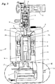
- the first alternative 10 of the welding device according to the invention has an ultrasonic welding unit 18 that can be moved as a whole in the direction of a counter-organ 17 or counter-tool, for example an anvil, and in the opposite direction.
- the ultrasonic welding unit 18 At its end facing the opposing member 17, the ultrasonic welding unit 18 has an ultrasonic sonotrode 19 which is known per se in terms of its mode of operation and its structure and which is moved along with the movement of the ultrasonic welding unit 18.
- the materials 20, 21 to be welded are shown in FIG Fig. 2 two layers of film arranged next to or one above the other are shown.
- the materials 20, 21 can be, for example, the two sections 11, 12 of the film web 13.
- the two materials 20, 21 are arranged between the ultrasonic sonotrode 19 and the counter-element 17. During each welding process, the material 21 faces the opposing member 17 and rests against it, while the material 20 faces the ultrasonic sonotrode 19 and rests against it.
- the ultrasonic welding unit 18 also has a slide 23 mounted on longitudinal guides 22a, 22b on which, among other things, the ultrasonic sonotrode 19 and an ultrasonic converter 24 feeding the ultrasonic sonotrode 19 are attached or mounted.
- a tensioning member 25 is also arranged thereon, which will be discussed in more detail below.
- the ultrasonic welding unit 18 can be moved by means of the slide 23 relative to a stationary support part 26, in the present case a frame or frame on which the longitudinal guides 22a, 22b are attached or supported.
- a cooling air nozzle 27 is also attached to the support part 26 and supplies cold air to the sonotrode 19 to prevent excessive heating of the ultrasonic sonotrode 19 during operation of the device 10.
- coolant lines 28 are integrated into the counter element 17, via which coolant is fed to the counter element 17 during operation of the device 10 in order to prevent excessive heating of the counter element 17.
- coolant for example, water can be used as the coolant.
- Adjustment means 29 can be seen, in the present case screws, with which the spatial position of the counter-organ 17 can be adjusted relative to the ultrasonic sonotrode 19 or with which the ultrasonic sonotrode 19 can be aligned.
- the movement of the ultrasonic welding unit 18 relative to the support part 26 or to the counter member 17 and the materials 20, 21 to be welded takes place by means of an electric drive motor 30, in the present case a servo motor.
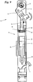
- the connecting rod 32 is operatively connected to the ultrasonic welding unit 18, so that a movement of the crankshaft 31 in a first direction, cf. Fig. 5 , causes a (downward) movement of the ultrasonic welding unit 18 in the direction of the counter-member 17, that is to say towards the counter-member 17.
- crankshaft 31 accordingly causes a (upwardly directed) movement of the ultrasonic welding unit 18 in the opposite direction, that is to say away from the counter member 17.
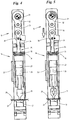
- the ultrasonic welding unit 18 can independently of the vibrations or ultrasonic movements of the ultrasonic sonotrode 19 from a non-welding position, cf. for example Fig. 4 , in which the ultrasonic sonotrode 19 does not transmit any vibrations or oscillations to the materials 20, 21, are moved into a welding position, cf. for example Fig. 5 in which this is the case.
- the connecting rod 32 is connected to the ultrasonic welding unit 18 via an intermediate piece 18, which on the one hand is articulated to the connecting rod 32 and, on the other hand, is articulated to the clamping member 25.
- the tensioning element 25 comprises a (rod-like) lifting element 34 or a stamp which is mounted within a present (hollow) cylindrical housing 35 such that it can be displaced or moved relative to it.
- the clamping element 25 is ultimately part of the ultrasonic welding unit 18.
- the housing 35 of the same is fixedly arranged on the slide 23 or attached to it.
- the lifting element 34 which can be moved within the housing 35, is indirectly connected to the drive motor 30 at its end facing away from the housing 35 - as already indicated above (via the intermediate piece 33, the connecting rod 32 and the crankshaft 31). At its other end, it is supported on a membrane 36 arranged inside the housing 35.
- the clamping element 25 has the task of compensating for this yielding or compensating for this yielding when one of the materials 20, 21 or both materials to be welded yields, in particular when these become thinner due to the energy input during the welding process as a result of plasticizing processes to counteract.
- the clamping member 25 in the welding position is elongated in the longitudinal direction when the materials 20, 21 yield, which results in the ultrasonic welding unit 18 and therefore also the ultrasonic sonotrode 19 moving in the direction of the yielding materials 20, 21.
- the clamping module 25 is designed in the present case as a pneumatic clamping module.
- the non-welding position of the welding device 10 or the ultrasonic welding unit 18 shown here is the clamping module 25 in a targeted manner by means of compressed air from a non-illustrated, controllable or regulatable compressed air reservoir into the in Fig. 6 position shown preloaded.
- the membrane 36 of the clamping module 25 is acted upon by the compressed air in such a way that its in Fig. 6
- the curvature shown as well as the stroke 37a or the position shown of the stroke element 34 resting on the membrane 36 is adjusted accordingly.
- the clamping module 25 has, in the present case, a first, larger (maximum) longitudinal extent or longitudinal dimension (in the present case defined by the distance between the end of the connecting rod 32 facing the Lifting element 34 on the one hand and the end of the housing 35 facing the slide 35 on the other hand).
- Fig. 7 the device 10 is shown immediately after approaching (lowering) the ultrasonic welding unit 18 in the direction of the opposing organ 17 and immediately after the start of the welding process, i.e. in particular after transferring the ultrasonic welding unit 18 into a welding position in which the ultrasonic sonotrode 19 is ultrasound into the materials 20, 21 is initiated.
- the transfer of the ultrasonic welding unit 18 into the welding position causes the sonotrode 19 to be supported on the counter-organ 17 (via the materials 20, 21) and, as a result, a corresponding counter-force of the counter-organ 17 in the direction of the clamping element 25.
- the individual components of the device 10 are Matched to one another in such a way that this counterforce compresses the tensioning element 25 against opposing tensioning forces applied by the compressed air of the tensioning element 25 or shortens its length. Specifically, the housing 35 (in the longitudinal direction) of the tensioning member 25 is moved relative to the lifting element 34, whereby the membrane 36 is compressed. The punch stroke 37b that occurs at the end of this process is off compared to the punch stroke 37a Fig. 6 smaller.
- Fig. 8 a later state is now shown in which welding energy has already been introduced into the materials 20, 21 for a certain time.
- the materials 20, 21 have yielded, that is, their thickness has been reduced in the present case.
- the tensioning member 25 has compensated for this yielding - by means of its tensioning forces - by expanding or increasing its length.
- the housing 35 has moved relative to the lifting element 34 by a distance 37c in the direction of the counter member 17 (or downwards).
- the ultrasonic welding unit 18 and with it the ultrasonic sonotrode 19 also move accordingly in the direction of the counter-organ 17.
- the air pressure of the tensioning member 25, that is to say the air pressure acting on the membrane 36 is preferably kept constant by the compressed air reservoir being controlled or regulated accordingly.
- Corresponding pressure controls with which this is possible are well known in the prior art.
- regulation / control of the air pressure is also conceivable, in which the air pressure is not kept constant but is changed as a function of the desired welding pressure during the movements. Examples based on signals from a welding pressure sensor that measures the current welding pressure. Or according to the stored control curves that depend on the movement of the ultrasonic welding unit. Many variants are conceivable here.
- the air pressure is not regulated or controlled at all, but adjusts itself independently depending on the respective state of movement.
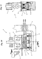
- the device 10 can be transferred to a cleaning position outside of standard operation, cf. Fig. 9 , within which parts of the device 10 can be easily removed or dismantled for cleaning.
- an articulated joint is arranged between the drive motor 30 and the ultrasonic welding unit 18, which can be transferred from a non-angled operating position in which the articulated joint can transfer kinetic energy of the drive motor 30 to move the ultrasonic welding unit 18 to an angled cleaning position, in which, due to the angled position of the articulated joint, the ultrasonic welding unit 18 has a greater distance from the counter-member 17 than in the operating position.
- a first arm of the articulated joint is formed by the intermediate piece 33, a second arm by the connecting rod 32 that is rotatably hinged to the intermediate piece 33.
- the articulation can from the in the Figure 2-8 position shown, in which it is not angled or in which both arms of the same are aligned and aligned in the longitudinal direction of the device 10, can be pivoted into an angled cleaning position.
- a locking pin 38 can be released by an operator, which prevents the articulated lever and in particular the intermediate piece 33 from pivoting relative to the connecting rod 32 or the lifting element 34 when the device 10 is in operation. Then the two arms of the toggle lever can be manually inserted into the in Fig. 9 shown, angled position are pivoted.
- the ultrasonic welding unit 18 or the carriage 23 are moved away from the counter-organ 17 (upwards) into the cleaning position in which the counter-organ 17 is accessible and in which it is possible to remove the counter-organ 17.
- the counter-member 17 is designed in several parts for this purpose. So the upper one, in Fig. 9 The part shown of the same can be arranged on a lower base part, for example via magnets, and correspondingly be solved in a simple manner, cf. Fig. 9 and 11 .
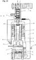
- FIG. 12 finally, the alternative 10 'shows a welding device according to the invention. Functionally identical components have the same reference numerals as in FIGS Figure 2-11 marked.
- the clamping member 25 is not assigned to the ultrasonic welding unit 18 or is arranged on it. Rather, the tensioning element 25 is assigned to the counter element 17.
- the ultrasonic welding unit 18 is not moved, but rather the counter element 17, specifically (upward) in the direction of the ultrasonic sonotrode 19.
- the counter element 17 is in the in Fig. 12
- the manner shown is movably supported on the support part 26 by means of corresponding longitudinal guides 22a, 22b.
Landscapes
- Engineering & Computer Science (AREA)
- Mechanical Engineering (AREA)
- Physics & Mathematics (AREA)
- Thermal Sciences (AREA)
- Fluid Mechanics (AREA)
- Lining Or Joining Of Plastics Or The Like (AREA)
- Pressure Welding/Diffusion-Bonding (AREA)
Claims (15)
- Dispositif de soudage par ultrasons de matériaux (20, 21), notamment de films, comprenant une unité de soudage par ultrasons (18) qui possède une sonotrode à ultrasons (19), comprenant un moteur d'entraînement électrique (30) destiné à déplacer l'unité de soudage par ultrasons (18) indépendamment du mouvement de soudage par ultrasons de la sonotrode à ultrasons (19), comprenant un organe de serrage (25), dont la longueur se réduit dans une position de soudage de l'unité de soudage par ultrasons (18) par rapport à une position de non-soudage en s'opposant à la résistance de forces de serrage orientées en sens inverse et dont la longueur augmente dans la position de soudage en raison de ses forces de serrage lors d'un relâchement d'au moins l'un des matériaux à souder pendant l'opération de soudage et qui, par l'augmentation de longueur, provoque un mouvement de l'unité de soudage par ultrasons (18) en direction du matériau qui se relâche, caractérisé en ce que l'organe de serrage (25) est à fonctionnement pneumatique.
- Dispositif de soudage par ultrasons de matériaux (20, 21), notamment de films, comprenant une unité de soudage par ultrasons (18) qui possède une sonotrode à ultrasons (19), comprenant un moteur d'entraînement électrique (30) destiné à déplacer l'unité de soudage par ultrasons (18) indépendamment du mouvement de soudage par ultrasons de la sonotrode à ultrasons (19) en direction d'un organe homologue (17) entre lequel organe homologue et la sonotrode à ultrasons (19) sont disposés les matériaux (20, 21) à souder pendant l'opération de soudage, et comprenant un organe de serrage (25) à fonctionnement pneumatique, dont la longueur se réduit dans une position de soudage de l'unité de soudage par ultrasons (18) par rapport à une position de non-soudage en s'opposant à la résistance de forces de serrage orientées en sens inverse et dont la longueur augmente dans la position de soudage en raison de ses forces de serrage lors d'un relâchement d'au moins l'un des matériaux à souder (20, 21) pendant l'opération de soudage et qui, par l'augmentation de longueur, provoque un mouvement de l'organe homologue (17) en direction de la sonotrode à ultrasons (19), l'organe de serrage (25) pouvant fonctionner de telle sorte que la force de serrage par parcours, qui s'oppose ou s'opposerait à une réduction de la longueur de l'organe de serrage (25) dans la position de soudage, est la même ou sensiblement la même avant l'augmentation de sa longueur lors du relâchement du matériau (20, 21) qu'après l'augmentation de sa longueur.
- Dispositif selon la revendication 1 ou 2, caractérisé en ce que l'organe de serrage (25), lors du déplacement de l'unité de soudage par ultrasons (18) de la position de non-soudage à la position de soudage, est transféré ou comprimé de l'état dans lequel il possède la plus grande longueur dans l'état où il possède une longueur plus petite par la force contraire d'un organe homologue (17), entre lequel organe homologue et la sonotrode à ultrasons sont disposés les matériaux (20, 21) à souder pendant l'opération de soudage.
- Dispositif selon la revendication 1 ou 3, caractérisé en ce que l'organe de serrage (25) fait partie de l'unité de soudage par ultrasons (18) qui peut être déplacée avec le moteur d'entraînement (30).
- Dispositif selon une ou plusieurs des revendications précédentes, caractérisé en ce que l'organe de serrage (25) possède une première zone ou un premier élément structural (34) ainsi qu'une deuxième zone ou un deuxième élément structural (35), qui peuvent être déplacés l'une par rapport à l'autre, notamment dans la direction longitudinale du dispositif (10, 10'), en vue de modifier la longueur.
- Dispositif selon la revendication 5, caractérisé en ce que le premier élément structural (34) ou la première zone est relié directement ou indirectement (à demeure) au moteur d'entraînement (30) et le deuxième élément structural (35) ou la deuxième zone est relié directement ou indirectement (à demeure) à la sonotrode à ultrasons (19) .
- Dispositif selon les revendications 5 ou 6, caractérisé en ce que la première zone ou le premier élément structural (34), dans l'état de l'organe de serrage (25) dans lequel il possède une longueur plus grande, présente un écart (longitudinal) de la deuxième zone ou du deuxième élément structural (35) supérieur à celui dans l'état dans lequel il possède une longueur plus petite.
- Dispositif selon une ou plusieurs des revendications précédentes, caractérisé en ce que l'organe de serrage (25) possède comme deuxième élément structural un boîtier (35) et comme premier élément structural un élément de levage (34) pouvant être déplacé par de l'air comprimé à l'intérieur du boîtier (35) par rapport à celui-ci.
- Dispositif selon la revendication 8, caractérisé en ce que l'organe de serrage (25) est raccordé à une source d'air comprimé, et en ce que la source d'air comprimé est commandée ou régulée de telle sorte que dans la position de soudage de l'unité de soudage par ultrasons (18), la pression d'air qui agit sur l'élément de levage (34) est identique ou sensiblement identique avant le relâchement du matériau (20, 21) et après le relâchement du matériau (20, 21).
- Dispositif selon une ou plusieurs des revendications précédentes, caractérisé en ce que le dispositif (10, 10') possède un vilebrequin (31) entraîné par le moteur d'entraînement (30) et relié à l'unité de soudage par ultrasons (18), lequel convertit les mouvements de rotation en mouvement de translation en vue de déplacer l'unité de soudage par ultrasons (18) dans la position de soudage ou hors de la position de soudage dans la position de non-soudage.
- Dispositif selon une ou plusieurs des revendications précédentes, caractérisé en ce que l'unité de soudage par ultrasons (18) est guidée pendant son mouvement de déplacement, notamment par un ou plusieurs guides (22a, 22b) .
- Dispositif selon une ou plusieurs des revendications précédentes, caractérisé en ce que l'organe de serrage (25) est disposé, conjointement avec la sonotrode à ultrasons (19) et un convertisseur d'ultrasons (24), sur un chariot (23) de l'unité de soudage par ultrasons (18) qui, lors du déplacement de l'unité de soudage par ultrasons (18), est déplacé en commun avec les composants mentionnés précédemment de la position de non-soudage dans la position de soudage.
- Dispositif selon la revendication 10, caractérisé en ce que la zone d'extrémité de l'élément de levage (34) qui est éloignée du boîtier (35) est reliée directement ou indirectement à une bielle (32) associée au vilebrequin (31).
- Dispositif selon une ou plusieurs des revendications précédentes, caractérisé en ce qu'un joint articulé est disposé entre le moteur d'entraînement (30) et l'unité de soudage par ultrasons (18), lequel peut être transféré d'une position de service non coudée, dans laquelle le joint articulé peut transmettre l'énergie motrice du moteur d'entraînement (30) à l'unité de soudage par ultrasons (18) en vue de déplacer celle-ci, à une position de nettoyage coudée, dans laquelle l'unité de soudage par ultrasons (18), du fait de la position coudée du joint articulé, présente un écart plus important par rapport à l'organe homologue (17) que dans la position de service.
- Dispositif selon les revendications 10 et 14, caractérisé en ce qu'un premier bras du joint articulé est formé par la bielle (32) et un deuxième bras par une pièce intermédiaire (33) articulée avec rotation à l'élément de levage (34)
Priority Applications (1)
| Application Number | Priority Date | Filing Date | Title |
|---|---|---|---|
| PL17000493T PL3231585T3 (pl) | 2016-04-11 | 2017-03-24 | Urządzenie do zgrzewania ultradźwiękowego |
Applications Claiming Priority (1)
| Application Number | Priority Date | Filing Date | Title |
|---|---|---|---|
| DE102016004180.3A DE102016004180A1 (de) | 2016-04-11 | 2016-04-11 | Vorrichtung zum Ultraschallschweißen |
Publications (3)
| Publication Number | Publication Date |
|---|---|
| EP3231585A1 EP3231585A1 (fr) | 2017-10-18 |
| EP3231585B1 true EP3231585B1 (fr) | 2020-10-14 |
| EP3231585B2 EP3231585B2 (fr) | 2026-04-15 |
Family
ID=58428034
Family Applications (1)
| Application Number | Title | Priority Date | Filing Date |
|---|---|---|---|
| EP17000493.1A Active EP3231585B2 (fr) | 2016-04-11 | 2017-03-24 | Dispositif de soudage par ultrasons |
Country Status (3)
| Country | Link |
|---|---|
| EP (1) | EP3231585B2 (fr) |
| DE (1) | DE102016004180A1 (fr) |
| PL (1) | PL3231585T3 (fr) |
Families Citing this family (5)
| Publication number | Priority date | Publication date | Assignee | Title |
|---|---|---|---|---|
| CN108555429B (zh) * | 2018-05-16 | 2023-06-20 | 华侨大学 | 金属箔大范围连续超声焊接装置 |
| CN112692423B (zh) * | 2020-12-16 | 2023-05-30 | 上海骄成超声波技术股份有限公司 | 超声波焊机 |
| CN112828439A (zh) * | 2020-12-31 | 2021-05-25 | 珠海灵科自动化科技有限公司 | 超声波焊接机及其工作方法 |
| CN114750417A (zh) * | 2022-03-25 | 2022-07-15 | 必能信超声(上海)有限公司 | 一种超声波塑料焊接机架 |
| CN119525681A (zh) * | 2024-12-04 | 2025-02-28 | 无锡海颂科技有限公司 | 焊接工装及焊接方法 |
Citations (10)
| Publication number | Priority date | Publication date | Assignee | Title |
|---|---|---|---|---|
| US5575884A (en) | 1994-09-28 | 1996-11-19 | Tetra Laval Holdings & Finance S.A. | Ultrasonic piston converter |
| WO1998038091A1 (fr) | 1997-02-26 | 1998-09-03 | Baxter International Inc. | Procede et appareil pour la fabrication de sacs a solution intraveineuse |
| JP2000141490A (ja) | 1998-11-04 | 2000-05-23 | Nippon Jido Seiki Kk | フィルム溶着装置 |
| US6491785B1 (en) | 1999-06-16 | 2002-12-10 | Ultex Corporation | Ultrasonic vibration bonding machine |
| US20040106506A1 (en) | 2001-03-28 | 2004-06-03 | Akihide Ninomiya | Sealing apparatus and manufacturing process of soft article having sealed portion |
| US20070251362A1 (en) | 2006-04-26 | 2007-11-01 | Herrmann Ultraschalltechnik Gmbh & Co.Kg | Device for processing workpieces using ultrasound and method for operating that device |
| US20070296104A1 (en) | 2005-10-20 | 2007-12-27 | Shannon Thomas G | High speed, pressure bonded, thin sheet laminate |
| US20080105385A1 (en) | 2006-05-11 | 2008-05-08 | Hans-Peter Wild | Anvil for ultrasonic welding and device for ultrasonic welding |
| US7819158B2 (en) | 2006-05-08 | 2010-10-26 | Dukane Corporation | Ultrasonic press using servo motor with integrated linear actuator |
| DE102011006932A1 (de) | 2011-04-07 | 2012-10-11 | Widmann Maschinen E.K. | Vorrichtung zum Schweißen und/oder Schneiden von Werkstücken |
Family Cites Families (5)
| Publication number | Priority date | Publication date | Assignee | Title |
|---|---|---|---|---|
| EP0790888B1 (fr) * | 1994-11-07 | 1999-06-09 | Herrmann Ultraschalltechnik GmbH & Co. KG | Procede et dispositif d'usinage en continu par ultrasons d'une bande de materiau |
| EP1833658B1 (fr) * | 2005-01-03 | 2016-07-27 | 3M Innovative Properties Company | Reglage d'intervalle pour un systeme de soudure ultrasonore |
| DE102010060401A1 (de) * | 2010-11-08 | 2012-05-10 | Sartorius Weighing Technology Gmbh | Schweißvorrichtung, Verwendung derselben als Steuerventil und Dosiervorrichtung |
| JP5779761B2 (ja) * | 2011-09-15 | 2015-09-16 | 精電舎電子工業株式会社 | 超音波溶着装置、超音波接合装置、布線装置 |
| US9550323B2 (en) * | 2013-09-06 | 2017-01-24 | GM Global Technology Operations LLC | Systems and methods for adaptive process control using a target kinematics profile in welding together multiple polymeric workpieces |
-
2016
- 2016-04-11 DE DE102016004180.3A patent/DE102016004180A1/de not_active Withdrawn
-
2017
- 2017-03-24 EP EP17000493.1A patent/EP3231585B2/fr active Active
- 2017-03-24 PL PL17000493T patent/PL3231585T3/pl unknown
Patent Citations (10)
| Publication number | Priority date | Publication date | Assignee | Title |
|---|---|---|---|---|
| US5575884A (en) | 1994-09-28 | 1996-11-19 | Tetra Laval Holdings & Finance S.A. | Ultrasonic piston converter |
| WO1998038091A1 (fr) | 1997-02-26 | 1998-09-03 | Baxter International Inc. | Procede et appareil pour la fabrication de sacs a solution intraveineuse |
| JP2000141490A (ja) | 1998-11-04 | 2000-05-23 | Nippon Jido Seiki Kk | フィルム溶着装置 |
| US6491785B1 (en) | 1999-06-16 | 2002-12-10 | Ultex Corporation | Ultrasonic vibration bonding machine |
| US20040106506A1 (en) | 2001-03-28 | 2004-06-03 | Akihide Ninomiya | Sealing apparatus and manufacturing process of soft article having sealed portion |
| US20070296104A1 (en) | 2005-10-20 | 2007-12-27 | Shannon Thomas G | High speed, pressure bonded, thin sheet laminate |
| US20070251362A1 (en) | 2006-04-26 | 2007-11-01 | Herrmann Ultraschalltechnik Gmbh & Co.Kg | Device for processing workpieces using ultrasound and method for operating that device |
| US7819158B2 (en) | 2006-05-08 | 2010-10-26 | Dukane Corporation | Ultrasonic press using servo motor with integrated linear actuator |
| US20080105385A1 (en) | 2006-05-11 | 2008-05-08 | Hans-Peter Wild | Anvil for ultrasonic welding and device for ultrasonic welding |
| DE102011006932A1 (de) | 2011-04-07 | 2012-10-11 | Widmann Maschinen E.K. | Vorrichtung zum Schweißen und/oder Schneiden von Werkstücken |
Also Published As
| Publication number | Publication date |
|---|---|
| EP3231585B2 (fr) | 2026-04-15 |
| DE102016004180A1 (de) | 2017-10-12 |
| PL3231585T3 (pl) | 2021-05-04 |
| EP3231585A1 (fr) | 2017-10-18 |
Similar Documents
| Publication | Publication Date | Title |
|---|---|---|
| EP3231585B1 (fr) | Dispositif de soudage par ultrasons | |
| EP0456121B1 (fr) | Procédé pour le pliage d'objets plats ainsi que la machine de pliage pour la mise en oeuvre du procédé | |
| DE102007051894B4 (de) | Freigabemechanismus und mit diesem versehenen Richtvorrichtung | |
| EP1915270B1 (fr) | Procede pour assembler le bord de profils d'etancheite et dispositif pour le mettre en oeuvre | |
| DE102012102527B4 (de) | Pressenantrieb mit mehreren Arbeitsbereichen | |
| EP2008736B1 (fr) | Machine-outil et procédé destinés à l'évacuation d'une partie d'une pièce à usiner | |
| DE102018000344B3 (de) | Biegemaschine, Biegeeinheit, elektronische Steuereinrichtung und Verfahren zum Biegen eines Werkstücks aus Flachmaterial | |
| EP2842718A2 (fr) | Outil d'extrusion destiné à la production de préformes en forme de tuyau | |
| EP3645188B1 (fr) | Procédé de fabrication d'une pièce pliée et machine de pliage pour la mise en oeuvre du procédé | |
| DE102014103101B4 (de) | Verfahren zur Herstellung blasgeformter Kunststoffhohlkörper und Mehrfachextrusionskopf zur Durchführung des Verfahrens | |
| DE202020002598U1 (de) | Biegemaschine zum Biegen eines Werkstücks aus Flachmaterial und Steuereinheit für eine solche Biegemaschine | |
| EP2661353A1 (fr) | Dispositif et procédé de fabrication de corps tubulaires pour tubes d'emballage | |
| EP3222407B1 (fr) | Automate de soudage | |
| EP3160726B1 (fr) | Presse à châssis en c, améliorée | |
| EP3186031B1 (fr) | Procédé de saignage dans des pièces métalliques au moyen d'un faisceau laser ainsi que machine d'usinage à laser et produit de programme informatique associés | |
| EP2447043A2 (fr) | Procédé de scellement économe en énergie de sachets tubulaires | |
| EP3208071B1 (fr) | Machine de soudage automatique | |
| EP2095930A2 (fr) | Procédé et dispositif de liage d'objets | |
| DE102012111117A1 (de) | Extrusionswerkzeug zur Erzeugung eines schlauchförmigen Vorformlings aus einer Kunststoffschmelze | |
| DE102015006421B4 (de) | Verfahren zum Fügen von Bauteilen | |
| EP1892188B1 (fr) | Dispositif de soudage des bords longitudinaux d'une ébauche de sachet | |
| WO2014191284A1 (fr) | Presse et procédé permettant de faire fonctionner la presse | |
| DE102014104641B4 (de) | Schweißelektrodeneinheit und Verfahren zum Buckelschweißen | |
| EP1870179A2 (fr) | Dispositif pour l' avancement cadencé d'une bande de matière | |
| EP1946906B1 (fr) | Procédé destiné à la fermeture du côté frontal d'une plaque de chambre creuse ainsi que dispositif d'exécution du procédé |
Legal Events
| Date | Code | Title | Description |
|---|---|---|---|
| PUAI | Public reference made under article 153(3) epc to a published international application that has entered the european phase |
Free format text: ORIGINAL CODE: 0009012 |
|
| STAA | Information on the status of an ep patent application or granted ep patent |
Free format text: STATUS: THE APPLICATION HAS BEEN PUBLISHED |
|
| AK | Designated contracting states |
Kind code of ref document: A1 Designated state(s): AL AT BE BG CH CY CZ DE DK EE ES FI FR GB GR HR HU IE IS IT LI LT LU LV MC MK MT NL NO PL PT RO RS SE SI SK SM TR |
|
| AX | Request for extension of the european patent |
Extension state: BA ME |
|
| STAA | Information on the status of an ep patent application or granted ep patent |
Free format text: STATUS: REQUEST FOR EXAMINATION WAS MADE |
|
| 17P | Request for examination filed |
Effective date: 20180417 |
|
| RBV | Designated contracting states (corrected) |
Designated state(s): AL AT BE BG CH CY CZ DE DK EE ES FI FR GB GR HR HU IE IS IT LI LT LU LV MC MK MT NL NO PL PT RO RS SE SI SK SM TR |
|
| STAA | Information on the status of an ep patent application or granted ep patent |
Free format text: STATUS: EXAMINATION IS IN PROGRESS |
|
| 17Q | First examination report despatched |
Effective date: 20190704 |
|
| GRAP | Despatch of communication of intention to grant a patent |
Free format text: ORIGINAL CODE: EPIDOSNIGR1 |
|
| STAA | Information on the status of an ep patent application or granted ep patent |
Free format text: STATUS: GRANT OF PATENT IS INTENDED |
|
| RIC1 | Information provided on ipc code assigned before grant |
Ipc: B29L 7/00 20060101ALN20200402BHEP Ipc: B29C 65/08 20060101AFI20200402BHEP |
|
| INTG | Intention to grant announced |
Effective date: 20200506 |
|
| GRAS | Grant fee paid |
Free format text: ORIGINAL CODE: EPIDOSNIGR3 |
|
| RIN1 | Information on inventor provided before grant (corrected) |
Inventor name: SCHNAKENBERG, JAN Inventor name: LEIFHEIT, AXEL Inventor name: STORCKS, ANDREAS |
|
| GRAA | (expected) grant |
Free format text: ORIGINAL CODE: 0009210 |
|
| STAA | Information on the status of an ep patent application or granted ep patent |
Free format text: STATUS: THE PATENT HAS BEEN GRANTED |
|
| AK | Designated contracting states |
Kind code of ref document: B1 Designated state(s): AL AT BE BG CH CY CZ DE DK EE ES FI FR GB GR HR HU IE IS IT LI LT LU LV MC MK MT NL NO PL PT RO RS SE SI SK SM TR |
|
| REG | Reference to a national code |
Ref country code: GB Ref legal event code: FG4D Free format text: NOT ENGLISH |
|
| REG | Reference to a national code |
Ref country code: CH Ref legal event code: EP Ref country code: AT Ref legal event code: REF Ref document number: 1323152 Country of ref document: AT Kind code of ref document: T Effective date: 20201015 |
|
| REG | Reference to a national code |
Ref country code: DE Ref legal event code: R096 Ref document number: 502017007696 Country of ref document: DE |
|
| REG | Reference to a national code |
Ref country code: IE Ref legal event code: FG4D Free format text: LANGUAGE OF EP DOCUMENT: GERMAN |
|
| REG | Reference to a national code |
Ref country code: NL Ref legal event code: FP |
|
| PG25 | Lapsed in a contracting state [announced via postgrant information from national office to epo] |
Ref country code: GR Free format text: LAPSE BECAUSE OF FAILURE TO SUBMIT A TRANSLATION OF THE DESCRIPTION OR TO PAY THE FEE WITHIN THE PRESCRIBED TIME-LIMIT Effective date: 20210115 Ref country code: FI Free format text: LAPSE BECAUSE OF FAILURE TO SUBMIT A TRANSLATION OF THE DESCRIPTION OR TO PAY THE FEE WITHIN THE PRESCRIBED TIME-LIMIT Effective date: 20201014 Ref country code: NO Free format text: LAPSE BECAUSE OF FAILURE TO SUBMIT A TRANSLATION OF THE DESCRIPTION OR TO PAY THE FEE WITHIN THE PRESCRIBED TIME-LIMIT Effective date: 20210114 Ref country code: RS Free format text: LAPSE BECAUSE OF FAILURE TO SUBMIT A TRANSLATION OF THE DESCRIPTION OR TO PAY THE FEE WITHIN THE PRESCRIBED TIME-LIMIT Effective date: 20201014 Ref country code: PT Free format text: LAPSE BECAUSE OF FAILURE TO SUBMIT A TRANSLATION OF THE DESCRIPTION OR TO PAY THE FEE WITHIN THE PRESCRIBED TIME-LIMIT Effective date: 20210215 |
|
| REG | Reference to a national code |
Ref country code: LT Ref legal event code: MG4D |
|
| PG25 | Lapsed in a contracting state [announced via postgrant information from national office to epo] |
Ref country code: ES Free format text: LAPSE BECAUSE OF FAILURE TO SUBMIT A TRANSLATION OF THE DESCRIPTION OR TO PAY THE FEE WITHIN THE PRESCRIBED TIME-LIMIT Effective date: 20201014 Ref country code: IS Free format text: LAPSE BECAUSE OF FAILURE TO SUBMIT A TRANSLATION OF THE DESCRIPTION OR TO PAY THE FEE WITHIN THE PRESCRIBED TIME-LIMIT Effective date: 20210214 Ref country code: LV Free format text: LAPSE BECAUSE OF FAILURE TO SUBMIT A TRANSLATION OF THE DESCRIPTION OR TO PAY THE FEE WITHIN THE PRESCRIBED TIME-LIMIT Effective date: 20201014 Ref country code: BG Free format text: LAPSE BECAUSE OF FAILURE TO SUBMIT A TRANSLATION OF THE DESCRIPTION OR TO PAY THE FEE WITHIN THE PRESCRIBED TIME-LIMIT Effective date: 20210114 Ref country code: SE Free format text: LAPSE BECAUSE OF FAILURE TO SUBMIT A TRANSLATION OF THE DESCRIPTION OR TO PAY THE FEE WITHIN THE PRESCRIBED TIME-LIMIT Effective date: 20201014 |
|
| PG25 | Lapsed in a contracting state [announced via postgrant information from national office to epo] |
Ref country code: HR Free format text: LAPSE BECAUSE OF FAILURE TO SUBMIT A TRANSLATION OF THE DESCRIPTION OR TO PAY THE FEE WITHIN THE PRESCRIBED TIME-LIMIT Effective date: 20201014 |
|
| REG | Reference to a national code |
Ref country code: DE Ref legal event code: R026 Ref document number: 502017007696 Country of ref document: DE |
|
| PLBI | Opposition filed |
Free format text: ORIGINAL CODE: 0009260 |
|
| PG25 | Lapsed in a contracting state [announced via postgrant information from national office to epo] |
Ref country code: LT Free format text: LAPSE BECAUSE OF FAILURE TO SUBMIT A TRANSLATION OF THE DESCRIPTION OR TO PAY THE FEE WITHIN THE PRESCRIBED TIME-LIMIT Effective date: 20201014 Ref country code: SM Free format text: LAPSE BECAUSE OF FAILURE TO SUBMIT A TRANSLATION OF THE DESCRIPTION OR TO PAY THE FEE WITHIN THE PRESCRIBED TIME-LIMIT Effective date: 20201014 Ref country code: EE Free format text: LAPSE BECAUSE OF FAILURE TO SUBMIT A TRANSLATION OF THE DESCRIPTION OR TO PAY THE FEE WITHIN THE PRESCRIBED TIME-LIMIT Effective date: 20201014 Ref country code: CZ Free format text: LAPSE BECAUSE OF FAILURE TO SUBMIT A TRANSLATION OF THE DESCRIPTION OR TO PAY THE FEE WITHIN THE PRESCRIBED TIME-LIMIT Effective date: 20201014 Ref country code: SK Free format text: LAPSE BECAUSE OF FAILURE TO SUBMIT A TRANSLATION OF THE DESCRIPTION OR TO PAY THE FEE WITHIN THE PRESCRIBED TIME-LIMIT Effective date: 20201014 Ref country code: RO Free format text: LAPSE BECAUSE OF FAILURE TO SUBMIT A TRANSLATION OF THE DESCRIPTION OR TO PAY THE FEE WITHIN THE PRESCRIBED TIME-LIMIT Effective date: 20201014 |
|
| PLAX | Notice of opposition and request to file observation + time limit sent |
Free format text: ORIGINAL CODE: EPIDOSNOBS2 |
|
| 26 | Opposition filed |
Opponent name: G.D SOCIETA PER AZIONI Effective date: 20210713 |
|
| PG25 | Lapsed in a contracting state [announced via postgrant information from national office to epo] |
Ref country code: DK Free format text: LAPSE BECAUSE OF FAILURE TO SUBMIT A TRANSLATION OF THE DESCRIPTION OR TO PAY THE FEE WITHIN THE PRESCRIBED TIME-LIMIT Effective date: 20201014 |
|
| PG25 | Lapsed in a contracting state [announced via postgrant information from national office to epo] |
Ref country code: IT Free format text: LAPSE BECAUSE OF FAILURE TO SUBMIT A TRANSLATION OF THE DESCRIPTION OR TO PAY THE FEE WITHIN THE PRESCRIBED TIME-LIMIT Effective date: 20201014 Ref country code: MC Free format text: LAPSE BECAUSE OF FAILURE TO SUBMIT A TRANSLATION OF THE DESCRIPTION OR TO PAY THE FEE WITHIN THE PRESCRIBED TIME-LIMIT Effective date: 20201014 Ref country code: AL Free format text: LAPSE BECAUSE OF FAILURE TO SUBMIT A TRANSLATION OF THE DESCRIPTION OR TO PAY THE FEE WITHIN THE PRESCRIBED TIME-LIMIT Effective date: 20201014 |
|
| REG | Reference to a national code |
Ref country code: CH Ref legal event code: PL |
|
| GBPC | Gb: european patent ceased through non-payment of renewal fee |
Effective date: 20210324 |
|
| PG25 | Lapsed in a contracting state [announced via postgrant information from national office to epo] |
Ref country code: SI Free format text: LAPSE BECAUSE OF FAILURE TO SUBMIT A TRANSLATION OF THE DESCRIPTION OR TO PAY THE FEE WITHIN THE PRESCRIBED TIME-LIMIT Effective date: 20201014 |
|
| PLBB | Reply of patent proprietor to notice(s) of opposition received |
Free format text: ORIGINAL CODE: EPIDOSNOBS3 |
|
| REG | Reference to a national code |
Ref country code: BE Ref legal event code: MM Effective date: 20210331 |
|
| PG25 | Lapsed in a contracting state [announced via postgrant information from national office to epo] |
Ref country code: LU Free format text: LAPSE BECAUSE OF NON-PAYMENT OF DUE FEES Effective date: 20210324 Ref country code: LI Free format text: LAPSE BECAUSE OF NON-PAYMENT OF DUE FEES Effective date: 20210331 Ref country code: CH Free format text: LAPSE BECAUSE OF NON-PAYMENT OF DUE FEES Effective date: 20210331 Ref country code: IE Free format text: LAPSE BECAUSE OF NON-PAYMENT OF DUE FEES Effective date: 20210324 Ref country code: FR Free format text: LAPSE BECAUSE OF NON-PAYMENT OF DUE FEES Effective date: 20210331 Ref country code: GB Free format text: LAPSE BECAUSE OF NON-PAYMENT OF DUE FEES Effective date: 20210324 |
|
| PG25 | Lapsed in a contracting state [announced via postgrant information from national office to epo] |
Ref country code: IS Free format text: LAPSE BECAUSE OF FAILURE TO SUBMIT A TRANSLATION OF THE DESCRIPTION OR TO PAY THE FEE WITHIN THE PRESCRIBED TIME-LIMIT Effective date: 20210214 |
|
| PG25 | Lapsed in a contracting state [announced via postgrant information from national office to epo] |
Ref country code: BE Free format text: LAPSE BECAUSE OF NON-PAYMENT OF DUE FEES Effective date: 20210331 |
|
| REG | Reference to a national code |
Ref country code: AT Ref legal event code: MM01 Ref document number: 1323152 Country of ref document: AT Kind code of ref document: T Effective date: 20220324 |
|
| PG25 | Lapsed in a contracting state [announced via postgrant information from national office to epo] |
Ref country code: HU Free format text: LAPSE BECAUSE OF FAILURE TO SUBMIT A TRANSLATION OF THE DESCRIPTION OR TO PAY THE FEE WITHIN THE PRESCRIBED TIME-LIMIT; INVALID AB INITIO Effective date: 20170324 |
|
| P01 | Opt-out of the competence of the unified patent court (upc) registered |
Effective date: 20230517 |
|
| PG25 | Lapsed in a contracting state [announced via postgrant information from national office to epo] |
Ref country code: CY Free format text: LAPSE BECAUSE OF FAILURE TO SUBMIT A TRANSLATION OF THE DESCRIPTION OR TO PAY THE FEE WITHIN THE PRESCRIBED TIME-LIMIT Effective date: 20201014 |
|
| PG25 | Lapsed in a contracting state [announced via postgrant information from national office to epo] |
Ref country code: AT Free format text: LAPSE BECAUSE OF NON-PAYMENT OF DUE FEES Effective date: 20220324 |
|
| APBM | Appeal reference recorded |
Free format text: ORIGINAL CODE: EPIDOSNREFNO |
|
| APBP | Date of receipt of notice of appeal recorded |
Free format text: ORIGINAL CODE: EPIDOSNNOA2O |
|
| APAH | Appeal reference modified |
Free format text: ORIGINAL CODE: EPIDOSCREFNO |
|
| APBM | Appeal reference recorded |
Free format text: ORIGINAL CODE: EPIDOSNREFNO |
|
| APBP | Date of receipt of notice of appeal recorded |
Free format text: ORIGINAL CODE: EPIDOSNNOA2O |
|
| PLAB | Opposition data, opponent's data or that of the opponent's representative modified |
Free format text: ORIGINAL CODE: 0009299OPPO |
|
| APBQ | Date of receipt of statement of grounds of appeal recorded |
Free format text: ORIGINAL CODE: EPIDOSNNOA3O |
|
| R26 | Opposition filed (corrected) |
Opponent name: G.D SOCIETA PER AZIONI Effective date: 20210713 |
|
| PG25 | Lapsed in a contracting state [announced via postgrant information from national office to epo] |
Ref country code: MK Free format text: LAPSE BECAUSE OF FAILURE TO SUBMIT A TRANSLATION OF THE DESCRIPTION OR TO PAY THE FEE WITHIN THE PRESCRIBED TIME-LIMIT Effective date: 20201014 |
|
| PG25 | Lapsed in a contracting state [announced via postgrant information from national office to epo] |
Ref country code: TR Free format text: LAPSE BECAUSE OF FAILURE TO SUBMIT A TRANSLATION OF THE DESCRIPTION OR TO PAY THE FEE WITHIN THE PRESCRIBED TIME-LIMIT Effective date: 20201014 |
|
| PG25 | Lapsed in a contracting state [announced via postgrant information from national office to epo] |
Ref country code: MT Free format text: LAPSE BECAUSE OF FAILURE TO SUBMIT A TRANSLATION OF THE DESCRIPTION OR TO PAY THE FEE WITHIN THE PRESCRIBED TIME-LIMIT Effective date: 20201014 |
|
| PGFP | Annual fee paid to national office [announced via postgrant information from national office to epo] |
Ref country code: PL Payment date: 20250313 Year of fee payment: 9 |
|
| APBU | Appeal procedure closed |
Free format text: ORIGINAL CODE: EPIDOSNNOA9O |
|
| PUAH | Patent maintained in amended form |
Free format text: ORIGINAL CODE: 0009272 |
|
| STAA | Information on the status of an ep patent application or granted ep patent |
Free format text: STATUS: PATENT MAINTAINED AS AMENDED |
|
| REG | Reference to a national code |
Ref country code: CH Ref legal event code: M12 Free format text: ST27 STATUS EVENT CODE: U-0-0-M10-M12 (AS PROVIDED BY THE NATIONAL OFFICE) Effective date: 20260318 |
|
| PGFP | Annual fee paid to national office [announced via postgrant information from national office to epo] |
Ref country code: DE Payment date: 20260227 Year of fee payment: 10 |
|
| 27A | Patent maintained in amended form |
Effective date: 20260415 |
|
| AK | Designated contracting states |
Kind code of ref document: B2 Designated state(s): AL AT BE BG CH CY CZ DE DK EE ES FI FR GB GR HR HU IE IS IT LI LT LU LV MC MK MT NL NO PL PT RO RS SE SI SK SM TR |
|
| REG | Reference to a national code |
Ref country code: DE Ref legal event code: R102 Ref document number: 502017007696 Country of ref document: DE |
|
| PGFP | Annual fee paid to national office [announced via postgrant information from national office to epo] |
Ref country code: NL Payment date: 20260323 Year of fee payment: 10 |