EP3231648B1 - Fahrzeug, insbesondere nutzfahrzeug, mit energiegewinnungsanlage - Google Patents
Fahrzeug, insbesondere nutzfahrzeug, mit energiegewinnungsanlage Download PDFInfo
- Publication number
- EP3231648B1 EP3231648B1 EP17161504.0A EP17161504A EP3231648B1 EP 3231648 B1 EP3231648 B1 EP 3231648B1 EP 17161504 A EP17161504 A EP 17161504A EP 3231648 B1 EP3231648 B1 EP 3231648B1
- Authority
- EP
- European Patent Office
- Prior art keywords
- vehicle
- subsystem
- control device
- energy generation
- energy
- Prior art date
- Legal status (The legal status is an assumption and is not a legal conclusion. Google has not performed a legal analysis and makes no representation as to the accuracy of the status listed.)
- Active
Links
Images

Classifications
-
- B—PERFORMING OPERATIONS; TRANSPORTING
- B60—VEHICLES IN GENERAL
- B60J—WINDOWS, WINDSCREENS, NON-FIXED ROOFS, DOORS, OR SIMILAR DEVICES FOR VEHICLES; REMOVABLE EXTERNAL PROTECTIVE COVERINGS SPECIALLY ADAPTED FOR VEHICLES
- B60J1/00—Windows; Windscreens; Accessories therefor
-
- B—PERFORMING OPERATIONS; TRANSPORTING
- B60—VEHICLES IN GENERAL
- B60K—ARRANGEMENT OR MOUNTING OF PROPULSION UNITS OR OF TRANSMISSIONS IN VEHICLES; ARRANGEMENT OR MOUNTING OF PLURAL DIVERSE PRIME-MOVERS IN VEHICLES; AUXILIARY DRIVES FOR VEHICLES; INSTRUMENTATION OR DASHBOARDS FOR VEHICLES; ARRANGEMENTS IN CONNECTION WITH COOLING, AIR INTAKE, GAS EXHAUST OR FUEL SUPPLY OF PROPULSION UNITS IN VEHICLES
- B60K16/00—Arrangements in connection with power supply of propulsion units in vehicles from forces of nature, e.g. sun or wind
-
- B—PERFORMING OPERATIONS; TRANSPORTING
- B60—VEHICLES IN GENERAL
- B60K—ARRANGEMENT OR MOUNTING OF PROPULSION UNITS OR OF TRANSMISSIONS IN VEHICLES; ARRANGEMENT OR MOUNTING OF PLURAL DIVERSE PRIME-MOVERS IN VEHICLES; AUXILIARY DRIVES FOR VEHICLES; INSTRUMENTATION OR DASHBOARDS FOR VEHICLES; ARRANGEMENTS IN CONNECTION WITH COOLING, AIR INTAKE, GAS EXHAUST OR FUEL SUPPLY OF PROPULSION UNITS IN VEHICLES
- B60K16/00—Arrangements in connection with power supply of propulsion units in vehicles from forces of nature, e.g. sun or wind
- B60K2016/003—Arrangements in connection with power supply of propulsion units in vehicles from forces of nature, e.g. sun or wind solar power driven
-
- B—PERFORMING OPERATIONS; TRANSPORTING
- B60—VEHICLES IN GENERAL
- B60Y—INDEXING SCHEME RELATING TO ASPECTS CROSS-CUTTING VEHICLE TECHNOLOGY
- B60Y2200/00—Type of vehicle
- B60Y2200/10—Road Vehicles
- B60Y2200/14—Trucks; Load vehicles, Busses
- B60Y2200/143—Busses
-
- Y—GENERAL TAGGING OF NEW TECHNOLOGICAL DEVELOPMENTS; GENERAL TAGGING OF CROSS-SECTIONAL TECHNOLOGIES SPANNING OVER SEVERAL SECTIONS OF THE IPC; TECHNICAL SUBJECTS COVERED BY FORMER USPC CROSS-REFERENCE ART COLLECTIONS [XRACs] AND DIGESTS
- Y02—TECHNOLOGIES OR APPLICATIONS FOR MITIGATION OR ADAPTATION AGAINST CLIMATE CHANGE
- Y02E—REDUCTION OF GREENHOUSE GAS [GHG] EMISSIONS, RELATED TO ENERGY GENERATION, TRANSMISSION OR DISTRIBUTION
- Y02E10/00—Energy generation through renewable energy sources
- Y02E10/50—Photovoltaic [PV] energy
-
- Y—GENERAL TAGGING OF NEW TECHNOLOGICAL DEVELOPMENTS; GENERAL TAGGING OF CROSS-SECTIONAL TECHNOLOGIES SPANNING OVER SEVERAL SECTIONS OF THE IPC; TECHNICAL SUBJECTS COVERED BY FORMER USPC CROSS-REFERENCE ART COLLECTIONS [XRACs] AND DIGESTS
- Y02—TECHNOLOGIES OR APPLICATIONS FOR MITIGATION OR ADAPTATION AGAINST CLIMATE CHANGE
- Y02T—CLIMATE CHANGE MITIGATION TECHNOLOGIES RELATED TO TRANSPORTATION
- Y02T10/00—Road transport of goods or passengers
- Y02T10/60—Other road transportation technologies with climate change mitigation effect
- Y02T10/7072—Electromobility specific charging systems or methods for batteries, ultracapacitors, supercapacitors or double-layer capacitors
-
- Y—GENERAL TAGGING OF NEW TECHNOLOGICAL DEVELOPMENTS; GENERAL TAGGING OF CROSS-SECTIONAL TECHNOLOGIES SPANNING OVER SEVERAL SECTIONS OF THE IPC; TECHNICAL SUBJECTS COVERED BY FORMER USPC CROSS-REFERENCE ART COLLECTIONS [XRACs] AND DIGESTS
- Y02—TECHNOLOGIES OR APPLICATIONS FOR MITIGATION OR ADAPTATION AGAINST CLIMATE CHANGE
- Y02T—CLIMATE CHANGE MITIGATION TECHNOLOGIES RELATED TO TRANSPORTATION
- Y02T10/00—Road transport of goods or passengers
- Y02T10/80—Technologies aiming to reduce greenhouse gasses emissions common to all road transportation technologies
- Y02T10/90—Energy harvesting concepts as power supply for auxiliaries' energy consumption, e.g. photovoltaic sun-roof
Definitions
- the invention relates to a vehicle with an energy recovery system, in particular a photovoltaic system.
- vehicle is preferably a motor vehicle, in particular a commercial vehicle, e.g. B. a bus or a truck.
- Photovoltaic modules are already known in a wide variety of embodiments in the prior art. So it is z. B. known to arrange photovoltaic modules on roof surfaces of motor vehicles.
- the photovoltaic modules usually represent an overall system that serves to feed electrical energy into an on-board network of the vehicle.
- the WO 2010/083408 A1 discloses a photovoltaic device for a vehicle that includes a plurality of solar modules that are electrically isolated from one another and are capable of receiving solar radiation and converting the radiation into electrical energy.
- the device contains at least one DC / DC converter that is electrically coupled to the galvanically isolated modules in order to receive the electrical energy from the solar modules and to increase the voltage that is to be supplied to at least one component of the vehicle.
- the WO 2009/077567 A2 discloses an electric motor vehicle that includes an electric motor, a rechargeable battery, and also a body made of an opaque material.
- the opaque material from which the body is made includes photovoltaic cells.
- the DE 10 2009 058891 A1 discloses a solar system for a vehicle, comprising a plurality of solar module devices, the solar module devices each comprising at least one solar module and being attachable to different areas of the vehicle's solar module.
- the solar system has a plurality of devices for extracting maximum power, each of the solar module devices being assigned one of the plurality of devices for extracting maximum power in order to be able to extract the currently maximum achievable power of the respective solar module devices.
- the DE 20 2008 010208 U1 discloses that an energy system of a motor vehicle comprising solar thin-film cells with triple junction technology can be used for energy generation. With the energy generated by the energy system, cooling units, Air conditioning, heaters of all kinds, such as auxiliary heating and seat heating are fully or partially supplied.
- An object of the invention is to provide a vehicle with an energy recovery system that enables an improved energy yield.
- the main goal is in particular the support (energy supply) of a vehicle electrical system (e.g. 24V vehicle network), the avoidance of deep discharge of one or more vehicle batteries (e.g. 24V vehicle batteries) and / or the provision of electrical energy to operate a climate -, ventilation and / or refrigeration system of the vehicle.
- a vehicle electrical system e.g. 24V vehicle network
- vehicle batteries e.g. 24V vehicle batteries
- the invention provides a vehicle, preferably a motor vehicle, in particular a commercial vehicle, e.g. B. a bus or a truck.
- a vehicle preferably a motor vehicle, in particular a commercial vehicle, e.g. B. a bus or a truck.
- the vehicle comprises a roof surface, an outer circumference and an energy generation system, which is a photovoltaic system, expediently for converting a part of solar radiation into electrical energy.
- the outer circumference comprises in particular two outer sides (eg “left” and “right” outer sides), a rear side, a front side and / or a roof area.
- the vehicle is characterized in particular by the fact that the energy recovery system comprises a first subsystem (expediently subarea) and at least one second subsystem (expediently subarea) and the first subsystem has its own first control device is assigned to control the first subsystem and the second subsystem is assigned its own second control device for controlling the second subsystem.
- the vehicle is characterized in particular by the fact that the outer circumference is used at least partially as a usable area for the first subsystem, so that the first subsystem preferably extends at least over a part of the outer circumference, eg. B. is integrated therein, mounted on it, applied to it and / or at least partially overlapping it.
- the outer circumference is used at least partially as a usable area for the first subsystem, so that the first subsystem preferably extends at least over a part of the outer circumference, eg. B. is integrated therein, mounted on it, applied to it and / or at least partially overlapping it.
- the invention can thus, in particular, expand the usable areas for an energy generation system to the outer circumference of the vehicle, which preferably also results in an expansion of the use of the energy and power obtained by means of the energy generation system.
- the benefits of the energy recovery system are preferably the provision of electrical energy to the vehicle electrical system (in particular 24V electrical system), the prevention of deep discharge (s) of one or more vehicle batteries (e.g. 24V batteries) and / or the provision of electrical energy for Operation of an air conditioning, ventilation and / or refrigeration system of the vehicle.
- the first subsystem can e.g. B. include at least one energy generation module (expediently photovoltaic module) and / or the second subsystem can e.g. B. include at least one energy generation module (expediently photovoltaic module).
- the outer circumference has at least one preferably transparent window pane, e.g. B. one or more side windows, at least one front window and / or a rear window.
- a transparent window pane e.g. B. one or more side windows, at least one front window and / or a rear window.
- the window pane serves as a usable area for the first subsystem and / or for the first subsystem to extend over the window pane.
- the first subsystem can preferably be applied to the window pane, integrated into the window pane and / or at least partially overlap the window pane, e.g. B. laterally spaced outside or inside relative to the window pane.
- the first subsystem in particular its at least one energy generation module, can e.g. B. semitransparent and / or from the vehicle interior from expediently at least slightly transparent.
- the outer circumference expediently comprises two outer sides (“left” vehicle side and “right” vehicle side), which preferably each have at least one window pane, a rear side which preferably has at least one window pane, a front side which preferably has a window pane, and / or a roof surface .
- the first subsystem can be arranged on one of the outer sides, the rear side, the front side and / or the roof surface, expediently.
- the second subsystem can be arranged on the other of the outer sides, the rear side, the front side and / or the roof surface, expediently.
- the first subsystem and / or the second subsystem can comprise at least one of the following: at least one semitransparent energy generation module, preferably at least one semitransparent thin-film photovoltaic module, at least one flexible energy generation module, e.g. B. at least one flexible thin-film photovoltaic module, at least one monocrystalline energy generation module, in particular a monocrystalline photovoltaic module, and / or at least one polycrystalline energy generation module, in particular a polycrystalline photovoltaic module.
- the energy generation system can be connected to an on-board electrical system and / or a vehicle battery, in particular a 24 V on-board electrical system and / or a 24 V vehicle battery, of the vehicle in order to supply the on-board electrical system and / or the vehicle battery with energy.
- the energy recovery system can be connected to an air conditioning, cooling and / or ventilation system of the vehicle in order to supply the air conditioning, cooling and / or ventilation system with appropriate electrical energy.
- first control device and / or the second control device can be connected to at least one control device for controlling the air conditioning, refrigeration and / or ventilation system of the vehicle.
- the first control device and / or the second control device and the at least one control device for the air conditioning, refrigeration and / or ventilation system can interact appropriately with one another.
- the first control device and / or the second control device can, for. B. include an MPP tracker (Maximum Power Point Tracker), in particular an MPP tracker current control unit.
- MPP tracker Maximum Power Point Tracker
- the first subsystem and / or the second subsystem can be oriented substantially perpendicular.
- the energy recovery system is designed as a photovoltaic system.
- control device for controlling z. B. can include a “control device for controlling” or can be designed as such.
- the first subsystem with its own control device and the second subsystem with its own control device can in particular be assigned to one of the outer sides, the rear side, the front side and / or the roof surface, that is to say in particular one and the same vehicle side .
- the first subsystem with its own control device is assigned to the rear side and the second subsystem with its own control device to the front side or according to another suitable combination of one outside, the other outside, the rear side, the front side and / or the roof area, that is especially different vehicle sides.
- one or more window panes can be used as usable area for one or more of the subsystems.
- the vehicle body can also be used as a usable area for one or more of the subsystems, so that a subsystem, for. B. can be integrated into or mounted on the vehicle body.
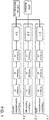
- Figure 1 shows a schematic representation of an energy production system, in particular a photovoltaic system, for a vehicle, in particular a motor vehicle, preferably a commercial vehicle, for. B. a truck or a bus.
- a photovoltaic system for a vehicle, in particular a motor vehicle, preferably a commercial vehicle, for. B. a truck or a bus.
- the energy generation system comprises a first subsystem 1.1, a second subsystem 1.2 and a third subsystem 1.n.
- the first subsystem 1.1 comprises a plurality of energy generation modules expediently designed as photovoltaic modules (PV modules).
- the second subsystem 1.2 comprises a plurality of energy generation modules which are expediently designed as photovoltaic modules (PV modules).
- the third subsystem 1.n comprises a plurality of energy generation modules which are expediently designed as photovoltaic modules (PV modules).
- the first subsystem 1.1 is assigned its own first control device 2.1 for controlling the first subsystem 1.1.
- the second subsystem 1.2 is assigned its own second control device 2.2 for controlling the second subsystem 1.2.
- the third subsystem 1.n is assigned its own third control device 2.n for controlling the third subsystem 1.n.
- control devices 2.1, 2.2 and 2.n are each designed as MPPT current controllers (MPPT ... Maximum Power Point Tracker) in order to be able to maximize the energy yield of the subsystems 1.1, 1.2 and 1.n appropriately.
- the energy generation system and thus its first subsystem 1.1, its second subsystem 1.2 and its third subsystem 1.n are connected to an electrical system, in particular a 24V electrical system, e.g. B. a 24V electrical system battery in connection to supply the same with electrical energy.
- the energy generation system and thus in turn its first subsystem 1.1, its second subsystem 1.2 and its third subsystem 1.n are connected to an air conditioning, refrigeration and / or ventilation system of the vehicle in order to supply the same with electrical energy.
- the first Control device 2.1, the second control device 2.2 and the third control device 2.n are connected to the control device for controlling the air conditioning, refrigeration and / or ventilation system.
- the connection to the 24V vehicle electrical system of the vehicle and the current control of each subsystem 1.1, 1.2 and 1.n are made by a separate control device 2.1, 2.2 and 2. n (e.g. current controller) implemented.
- FIG 2 shows a perspective view of a vehicle F according to an embodiment of the invention, preferably with an energy recovery system according to Figure 1 is equipped, so for this to the description Figure 1 is referenced to avoid repetitions.
- the vehicle F is in the Figure 2 embodiment shown a bus.
- the vehicle F includes a roof surface and an outer circumference.
- the outer circumference comprises two outer sides ("left” and “right” vehicle outer side), a rear side and a front side.
- the outer sides, the rear side and the front side each comprise one or more appropriately transparent window panes.
- the roof area used as a usable area for the energy production system, but also part of the outer circumference, namely the outer sides, in particular their window panes.
- the first subsystem 1.1 is applied to a window pane on one outside (eg "left" vehicle outside), integrated therein or at least partially overlaps the window pane, while the third subsystem 1.n is applied to a window pane on the other outside (eg " right "vehicle outside) is applied, is integrated therein or the window pane overlaps at least in sections.
- the second subsystem 1.2 is expediently arranged on the roof surface.
- the first subsystem 1.1 and the third subsystem 1.n are at least semi-transparent, in particular at least partially transparent from the interior of the vehicle F.
- the first subsystem 1.1 and the third subsystem 1.n comprise, in particular, semitransparent photovoltaic modules which can be used as side windows or side windows, to which semi-transparent thin-film photovoltaic modules are applied. Due to the semitransparent view of the side windows by the passenger is expediently guaranteed.
- z. B. opaque thin-film photovoltaic modules can be used, since looking through is not necessary here and a maximum energy yield is sought.
- the lightest possible (photovoltaic) module technologies must be used to keep the weight gain low.
- the (photovoltaic) module technology and the system size of the energy generation system particular care must be taken to ensure that the energy generated by the energy generation system is greater than the additional consumption of driving energy caused by the driving weight of the energy generation system.
- the invention in particular creates a structure of an energy recovery system having several subsystems 1.1, 1.2 and 1.n (subareas) with respective control devices 2.1, 2.2 and 2.n (control electronics) for integration into a 24V boron network.
- control devices 2.1, 2.2 and 2.n control electronics
- subsystems 1.1, 1.2 and 1.n each with its own control device 2.1, 2.2 and 2.n, these can expediently be used with different inclinations, positions and (photovoltaic) module technologies (eg "polycrystalline”, “monocrystalline”) ",” Thin film “and / or” flexible thin film ”) realized and with improved energy yield - compared to an undivided system - in the z.
- 24V electrical system can be integrated.
- the invention also provides, in particular, an expansion of the usable areas for the energy production system to the side window areas of the vehicle F, which otherwise represent a large undeveloped area on the vehicle F, and moreover preferably an expansion of the use of the energy and power of the energy production system.
- the benefits are in particular the support of the 24V vehicle electrical system, avoidance of deep discharge of the 24V vehicle batteries and / or provision of electrical energy for the operation of air conditioning, ventilation and cooling systems.
- the energy recovery system in particular enables the provision of electrical energy for the operation of air conditioning, ventilation and refrigeration systems.
- a major main advantage of the provision of electrical energy for the operation of air conditioning, ventilation and refrigeration systems through the energy production system is that the energy production system produces more energy the more sunlight falls on it and that the need for air conditioning and thus power is also greatest. If the solar radiation and thus the thermal energy entered into the vehicle F decrease, the air conditioning requirement also decreases. Due to the decreasing solar radiation, the energy production by the energy recovery system decreases at the same time.
- the necessary energy requirement of the 24 V vehicle electrical system of the vehicle F can be covered by the provision of electrical energy by the energy recovery system. This reduces the need for energy provision by a 24V generator / alternator, as is otherwise usually installed in commercial vehicles. Since the 24 V generator draws its energy from the drive torque of the engine F of the vehicle F, fossil energy can be saved in this way.
- the plant performance of an energy recovery plant depends directly on its size (e.g. number of PV modules) and its orientation to the incident sunlight. Since the usable space on a vehicle such. B. a city bus, do not have the same orientation, they are divided into individual subsystems / subareas 1.1, 1.2 and 1.n according to one embodiment of the invention.
- roof area, side area / outside "left", side area / outside "right” and / or rear area can be defined as usable areas.
Landscapes
- Engineering & Computer Science (AREA)
- Mechanical Engineering (AREA)
- Chemical & Material Sciences (AREA)
- Combustion & Propulsion (AREA)
- Transportation (AREA)
- Arrangement Or Mounting Of Propulsion Units For Vehicles (AREA)
Description
- Die Erfindung betrifft ein Fahrzeug mit einer Energiegewinnungsanlage, insbesondere einer Photovoltaikanlage. Das Fahrzeug ist vorzugsweise ein Kraftfahrzeug, insbesondere ein Nutzfahrzeug, z. B. ein Omnibus oder ein Lastkraftwagen.
- Kraftfahrzeuge mit Photovoltaikanlage sind im Stand der Technik bereits in unterschiedlichsten Ausführungsformen bekannt. So ist es z. B. bekannt, Photovoltaikmodule auf Dachflächen von Kraftfahrzeugen anzuordnen. Die Photovoltaikmodule stellen dabei meist ein Gesamtsystem dar, das dazu dient, elektrische Energie in ein Bordnetz des Fahrzeugs zu speisen.
- Die
WO 2010/083408 A1 offenbart eine Photovoltaikvorrichtung für ein Fahrzeug, die eine Vielzahl von Solarmodulen enthält, die elektrisch voneinander isoliert sind und geeignet sind, Sonnenstrahlung zu empfangen und die Strahlung in elektrische Energie umzuwandeln. Das Gerät enthält mindestens einen DC/DC-Wandler, der mit den galvanisch getrennten Modulen elektrisch gekoppelt ist, um die elektrische Energie von den Solarmodulen zu empfangen und die Spannung zu erhöhen, die an mindestens eine Komponente des Fahrzeugs geliefert werden soll. - Die
WO 2009/077567 A2 offenbart Kraftfahrzeug mit elektrischem Antrieb, das einen Elektromotor, eine wiederaufladbare Batterie und außerdem eine Karosserie umfasst, die aus einem lichtundurchlässigen Material verwirklicht ist. Das lichtundurchlässige Material, aus dem die Karosserie verwirklicht ist, umfasst photovoltaische Zellen. - Die
DE 10 2009 058891 A1 offenbart ein Solaranlagensystem für ein Fahrzeug, umfassend mehrere Solarmodulvorrichtungen, wobei die Solarmodulvorrichtungen jeweils mindestens ein Solarmodul umfassen und auf verschiedenen Solarmodulbereichen des Fahrzeugs anbringbar sind. Das Solaranlagensystem weist mehrere Vorrichtungen zur Maximalleistungsentnahme auf, wobei jeder der Solarmodulvorrichtungen eine der mehreren Vorrichtungen zur Maximalleistungsentnahme zugeordnet ist, um die aktuell maximal erreichbare Leistung der jeweiligen Solarmodulvorrichtungen entnehmen zu können. - Die
DE 20 2008 010208 U1 offenbart, dass ein Energiesystem eines Kraftfahrzeugs umfassend Solar-Dünnschichtzellen mit Triple-Junction-Technologie zur Energiegewinnung verendet werden kann. Mit der durch das Energiesystem gewonnenen Energie können Kühlaggregate, Klimaanlage, Heizungen aller Art, wie Standheizung und Sitzheizung komplett- oder teilversorgt werden. - Zum weiteren Stand der Technik wird auf die
DE 10 2008 009848 A1 , dieUS 2008/078194 A1 und dieWO 2011/094099 A1 hingewiesen. - Eine Aufgabe der Erfindung ist es, ein Fahrzeug mit einer Energiegewinnungsanlage zu schaffen, die eine verbesserte Energieausbeute ermöglicht. Hauptziel ist insbesondere die Stützung (Energieversorgung) eines Fahrzeugs-Bordnetzes (z. B. 24V-Bornetz), die Vermeidung einer Tiefentladung einer oder mehrerer Fahrzeugbatterien (z. B. 24V-Fahrzeugbatterien) und/oder die Bereitstellung elektrischer Energie zum Betrieb einer Klima-, Lüftungs- und/oder Kälteanlage des Fahrzeugs.
- Diese Aufgabe kann mit den Merkmalen des Hauptanspruchs gelöst werden. Vorteilhafte Weiterbildungen der Erfindung können den Unteransprüchen und der folgenden Beschreibung bevorzugter Ausführungsformen der Erfindung entnommen werden.
- Die Erfindung schafft ein Fahrzeug, vorzugsweise ein Kraftfahrzeug, insbesondere ein Nutzfahrzeug, z. B. einen Omnibus oder einen Lastkraftwagen.
- Das Fahrzeug umfasst eine Dachfläche, einen Außenumfang und eine Energiegewinnungsanlage, die eine Photovoltaikanlage ist, zweckmäßig zur Umwandlung eines Teils von Sonnenstrahlung in elektrische Energie. Der Außenumfang umfasst insbesondere zwei Außenseiten (z. B. "linke" und "rechte" Außenseiten), eine Heckseite, eine Frontseite und/oder eine Dachfläche.
- Das Fahrzeug zeichnet sich insbesondere dadurch aus, dass die Energiegewinnungsanlage ein erstes Teilsystem (zweckmäßig Teilfläche) und zumindest ein zweites Teilsystem (zweckmäßig Teilfläche) umfasst und dem ersten Teilsystem eine eigene erste Steuereinrichtung zum Steuern des ersten Teilsystems zugeordnet ist und dem zweiten Teilsystem eine eigene zweite Steuereinrichtung zum Steuern des zweiten Teilsystems zugeordnet ist.
- Alternativ oder ergänzend zeichnet sich das Fahrzeug insbesondere dadurch aus, dass der Außenumfang zumindest teilweise als Nutzfläche für das erste Teilsystem genutzt wird, so dass sich vorzugsweise das erste Teilsystem zumindest über einen Teil des Außenumfangs erstreckt, z. B. darin integriert ist, daran montiert ist, daran aufgebracht ist und/oder ihn zumindest abschnittsweise überlappt.
- Die Erfindung kann damit insbesondere eine Erweiterung der Nutzflächen für eine Energiegewinnungsanlage auf den Außenumfang des Fahrzeugs schaffen, woraus sich vorzugsweise auch eine Erweiterung der Nutzung der mittels der Energiegewinnungsanlage gewonnenen Energie und Leistung ergibt. Daraus ergeben sich insbesondere die Nutzung und der Verbund der Energiegewinnungsanlage auf unterschiedlichen Teilnutzflächen, um bei unterschiedlicher Fahrzeugausrichtung und/oder im Fahrbetrieb eine hohe Energieausbeute und verbesserte Leistungsbereitstellung erzielen zu können. Der Nutzen der Energiegewinnungsanlage ist vorzugsweise die Bereitstellung elektrischer Energie an das Fahrzeug-Bordnetz (insbesondere 24V-Bordnetz), die Vermeidung von Tiefentladung(en) einer oder mehrerer Fahrzeugbatterien (z. B. 24V-Batterien) und/oder die Bereitstellung elektrischer Energie zum Betrieb einer Klima-, Lüftungs- und/oder Kälteanlage des Fahrzeugs.
- Das erste Teilsystem kann z. B. zumindest ein Energiegewinnungsmodul (zweckmäßig Photovoltaikmodul) umfassen und/oder das zweite Teilsystem kann z. B. zumindest ein Energiegewinnungsmodul (zweckmäßig Photovoltaikmodul) umfassen.
- Es ist möglich, dass der Außenumfang zumindest eine vorzugsweise transparente Fensterscheibe aufweist, z. B. eine oder mehrere Seitenscheiben, zumindest eine Front-Fensterscheibe und/oder eine Heck-Fensterscheibe.
- Es ist möglich, dass die Fensterscheibe als Nutzfläche für das erste Teilsystem dient und/oder sich das erste Teilsystem über die Fensterscheibe erstreckt. Das erste Teilsystem kann vorzugsweise auf die Fensterscheibe aufgebracht sein, in die Fensterscheibe integriert sein und/oder die Fensterscheibe zumindest abschnittsweise überlappen, z. B. außen oder innen relativ zur Fensterscheibe seitlich beabstandet.
- Das erste Teilsystem, insbesondere dessen zumindest ein Energiegewinnungsmodul, kann z. B. semitransparent und/oder vom Fahrzeug-Innenraum aus zweckmäßig zumindest geringfügig durchschaubar ausgeführt sein.
- Der Außenumfang umfasst zweckmäßig zwei Außenseiten ("linke" Fahrzeugseite und "rechte" Fahrzeugseite), die vorzugsweise jeweils zumindest eine Fensterscheibe aufweisen, eine Heckseite, die vorzugsweise zumindest eine Fensterscheibe aufweist, eine Frontseite, die vorzugsweise eine Fensterscheibe aufweist, und/oder eine Dachfläche.
- Das erste Teilsystem kann an, zweckmäßig auf, einer der Außenseiten, der Heckseite, der Frontseite und/oder der Dachfläche angeordnet sein. Alternativ oder ergänzend kann das zweite Teilsystem an, zweckmäßig auf, der anderen der Außenseiten, der Heckseite, der Frontseite und/oder der Dachfläche angeordnet sein.
- Das erste Teilsystem und/oder das zweite Teilsystem kann zumindest eines von folgenden umfassen: zumindest ein semitransparentes Energiegewinnungsmodul, vorzugsweise zumindest ein semitransparentes Dünnschicht-Photovoltaik-Modul, zumindest ein flexibles Energiegewinnungsmodul, z. B. zumindest ein flexibles Dünnschicht-Photovoltaik-Modul, zumindest ein monokristallines Energiegewinnungsmodul, insbesondere ein monokristallines Photovoltaik-Modul, und/oder zumindest ein polykristallines Energiegewinnungsmodul, insbesondere ein polykristallines Photovoltaik-Modul.
- Es ist möglich, dass die Energiegewinnungsanlage mit einem Bordnetz und/oder einer Fahrzeugbatterie, insbesondere 24V-Bordnetz und/oder 24V-Fahrzeugbatterie, des Fahrzeugs in Verbindung steht, um das Bordnetz und/oder die Fahrzeugbatterie mit Energie zu versorgen. Alternativ oder ergänzend kann die Energiegewinnungsanlage mit einer Klima-, Kälte- und/oder Lüftungsanlage des Fahrzeugs in Verbindung stehen, um die Klima-, Kälte- und/oder Lüftungsanlage mit zweckmäßig elektrischer Energie zu versorgen.
- Es ist darüber hinaus möglich, dass die erste Steuereinrichtung und/oder die zweite Steuereinrichtung mit zumindest einer Steuereinrichtung zum Steuern der Klima-, Kälte- und/oder Lüftungsanlage des Fahrzeugs in Verbindung steht. Dabei können die erste Steuereinrichtung und/oder die zweite Steuereinrichtung und die zumindest eine Steuereinrichtung für die Klima-, Kälte- und/oder Lüftungsanlage zweckmäßig miteinander interagieren.
- Die erste Steuereinrichtung und/oder die zweite Steuereinrichtung kann z. B. einen MPP-Tracker (Maximum Power Point Tracker) umfassen, insbesondere eine MPP-Tracker-Stromsteuereinheit.
- Das erste Teilsystem und/oder das zweite Teilsystem kann im Wesentlichen senkrecht ausgerichtet sein.
- Die Energiegewinnungsanlage ist als Photovoltaikanlage ausgeführt.
- Zu erwähnen ist, dass im Rahmen der Erfindung das Merkmal "Steuereinrichtung zum Steuern" auch z. B. eine "Regeleinrichtung zum Regeln" umfassen kann oder als solche ausgeführt sein kann.
- Zu erwähnen ist ferner, dass im Rahmen der Erfindung das erste Teilsystem mit der eigenen Steuereinrichtung und das zweite Teilsystem mit der eigenen Steuereinrichtung insbesondere einer der Außenseiten, der Heckseite, der Frontseite und/oder der Dachfläche zugeordnet sein kann, also insbesondere ein und derselben Fahrzeugseite. Alternativ oder ergänzend ist es im Rahmen der Erfindung möglich, dass z. B. das erste Teilsystem mit der eigenen Steuereinrichtung der Heckseite und das zweite Teilsystem mit der eigenen Steuereinrichtung der Frontseite zugeordnet ist oder gemäß einer anderen geeigneten Kombination aus der einen Außenseite, der anderen Außenseite, der Heckseite, der Frontseite und/oder der Dachfläche, also insbesondere unterschiedlichen Fahrzeugseiten.
- Zu erwähnen ist außerdem, dass im Rahmen der Erfindung insbesondere eine oder mehrere Fensterscheiben als Nutzfläche für eines oder mehrere der Teilsysteme genutzt werden können. Alternativ oder ergänzend kann allerdings auch die Fahrzeugkarosserie als Nutzfläche für eines oder mehrere der Teilsysteme genutzt werden, so dass ein Teilsystem z. B. in die Fahrzeugkarosserie integriert oder daran aufmontiert sein kann.
- Die vorstehend beschriebenen bevorzugten Ausführungsformen und Merkmale der Erfindung sind miteinander kombinierbar. Andere vorteilhafte Weiterbildungen der Erfindung sind in den Unteransprüchen offenbart oder ergeben sich aus der folgenden Beschreibung bevorzugter Ausführungsformen der Erfindung in Verbindung mit den beigefügten Figuren.
- Figur 1
- zeigt eine schematische Darstellung einer Energiegewinnungsanlage gemäß einer Ausführungsform der Erfindung und
- Figur 2
- zeigt ein Fahrzeug gemäß einer Ausführungsform der Erfindung, vorzugsweise mit einer wie in
Figur 1 gezeigten Energiegewinnungsanlage. -
Figur 1 zeigt eine schematische Darstellung einer Energiegewinnungsanlage, insbesondere einer Photovoltaikanlage, für ein Fahrzeug, insbesondere ein Kraftfahrzeug, vorzugsweise ein Nutzfahrzeug, z. B. einen Lastkraftwagen oder einen Omnibus. - Die Energiegewinnungsanlage umfasst ein erstes Teilsystem 1.1, ein zweites Teilsystem 1.2 und ein drittes Teilsystem 1.n.
- Das erste Teilsystem 1.1 umfasst mehrere zweckmäßig als Photovoltaik-Module (PV-Module) ausgeführte Energiegewinnungsmodule. Das zweite Teilsystem 1.2 umfasst mehrere zweckmäßig als Photovoltaik-Module (PV-Module) ausgeführte Energiegewinnungsmodule. Das dritte Teilsystem 1.n umfasst mehrere zweckmäßig als Photovoltaik-Module (PV-Module) ausgeführte Energiegewinnungsmodule.
- Dem ersten Teilsystem 1.1 ist eine eigene erste Steuereinrichtung 2.1 zum Steuern des ersten Teilsystems 1.1 zugeordnet. Dem zweiten Teilsystem 1.2 ist eine eigene zweite Steuereinrichtung 2.2 zum Steuern des zweiten Teilsystems 1.2 zugeordnet ist. Darüber hinaus ist dem dritten Teilsystem 1.n eine eigene dritte Steuereinrichtung 2.n zum Steuern des dritten Teilsystems 1.n zugeordnet.
- Im Rahmen der Erfindung können auch nur zwei Teilsysteme 1.1 und 1.2 oder mehr als drei Teilsysteme (1.n, mit: n=4, n=5, usw.) zur Anwendung kommen, mit jeweils eigener Steuereinrichtung (2.n, mit: n=4, n=5, usw.).
- In der in
Figur 1 gezeigten Ausführungsform sind die Steuereinrichtungen 2.1, 2.2 und 2.n jeweils als MPPT-Stromregler (MPPT...Maximum Power Point Tracker) ausgeführt, um die Energieausbeute der Teilsysteme 1.1, 1.2 und 1.n zweckmäßig maximieren zu können. - Die Energiegewinnungsanlage und somit deren erstes Teilsystem 1.1, deren zweites Teilsystem 1.2 und deren drittes Teilsystem 1.n stehen mit einem Bordnetz, insbesondere einem 24V-Bordnetz, z. B. einer 24V-Bordnetz-Batterie in Verbindung, um selbige mit elektrischer Energie zu versorgen. Darüber hinaus steht die Energiegewinnungsanlage und somit wiederum deren erstes Teilsystem 1.1, deren zweites Teilsystem 1.2 und deren drittes Teilsystem 1.n mit einer Klima-, Kälte- und/oder Lüftungsanlage des Fahrzeugs in Verbindung, um selbige mit elektrischer Energie zu versorgen. Dabei ist es insbesondere möglich, dass die erste Steuereinrichtung 2.1, die zweite Steuereinrichtung 2.2 und die dritte Steuereinrichtung 2.n mit der Steuereinrichtung zum Steuern der Klima-, Kälte- und/oder Lüftungsanlage in Verbindung stehen.
- Damit die Energieausbeute der Teilsysteme 1.1, 1.2 und 1.n der Energiegewinnungsanlage möglichst groß ist, wird die Anbindung an das 24V-Bordnetz des Fahrzeugs und die Stromregelung jedes Teilsystems 1.1, 1.2 und 1.n durch eine eigene Steuereinrichtung 2.1, 2.2 und 2.n (z. B. Stromregler) realisiert.
-
Figur 2 zeigt eine perspektivische Ansicht eines Fahrzeugs F gemäß einer Ausführungsform der Erfindung, das vorzugsweise mit einer Energiegewinnungsanlage gemäßFigur 1 ausgestattet ist, so dass hierfür auf die Beschreibung zuFigur 1 verwiesen wird, um Wiederholungen zu vermeiden. Das Fahrzeug F ist in der inFigur 2 gezeigten Ausführungsform ein Omnibus. - Das Fahrzeug F umfasst eine Dachfläche und einen Außenumfang. Der Außenumfang umfasst zwei Außenseiten ("linke" und "rechte" Fahrzeugaußenseite), eine Heckseite und eine Frontseite. Die Außenseiten, die Heckseite und die Frontseite umfassen jeweils eine oder mehrere zweckmäßig transparente Fensterscheiben.
- Bei dem Fahrzeug F wird nicht nur die Dachfläche als Nutzfläche für die Energiegewinnungsanlage genutzt, sondern auch ein Teil des Außenumfangs, nämlich die Außenseiten, insbesondere deren Fensterscheiben.
- Das erste Teilsystem 1.1 ist auf eine Fensterscheibe der einen Außenseite (z. B "linke" Fahrzeugaußenseite) aufgebracht, darin integriert oder überlappt die Fensterscheibe zumindest abschnittsweise, während das dritte Teilsystem 1.n auf eine Fensterscheibe der anderen Außenseite (z. B. "rechte" Fahrzeugaußenseite) aufgebracht ist, darin integriert ist oder die Fensterscheibe zumindest abschnittsweise überlappt. Das zweite Teilsystem 1.2 ist zweckmäßig auf der Dachfläche angeordnet.
- Dabei ist besonders bevorzugt, dass das erste Teilsystem 1.1 und das dritte Teilsystem 1.n zumindest semitransparent ausgeführt sind, insbesondere vom Innenraum des Fahrzeugs F aus zumindest teilweise durchschaubar sind.
- Das erste Teilsystem 1.1 und das dritte Teilsystem 1.n umfasst insbesondere semitransparente Photovoltaikmodule, welche als Seitenscheiben eingesetzt werden können oder Seitenscheiben, auf welche semitransparente Dünnschicht-Photovoltaik-Module aufgebracht sind. Durch die Semitransparenz ist zweckmäßig ein Hindurchblicken der Seitenscheiben durch den Fahrgast gewährleistet.
- Im Bereich des Fahrzeugdaches können auch z. B. intransparente Dünnschicht-Photovoltaik-Module eingesetzt werden, da hier ein Hindurchblicken nicht erforderlich ist und eine maximale Energieausbeute angestrebt wird.
- Da die Energiegewinnungsanlage das Fahrzeuggewicht erhöht, sind möglichst leichte (Photovoltaik-) Modultechnologien einzusetzen, um den Gewichtszuwachs gering zu halten. Bei der Auswahl der (Photovoltaik-) Modultechnologie und der Systemgröße der Energiegewinnungsanlage ist insbesondere darauf zu achten, dass die erzeugte Energie durch die Energiegewinnungsanlage größer ist als der Mehrverbrauch an Fahrenergie, welche durch das Fahrgewicht der Energiegewinnungsanlage entsteht.
- Die Erfindung schafft insbesondere einen Aufbau einer mehrere Teilsysteme 1.1, 1.2 und 1.n (Teilflächen) aufweisenden Energiegewinnungsanlage mit jeweiliger Steuereinrichtung 2.1, 2.2 und 2.n (Regelelektronik) zur Einbindung in zweckmäßig ein 24V-Bornetz. Durch die Aufteilung der Energiegewinnungsanlage in Teilsysteme 1.1, 1.2 und 1.n mit jeweils eigener Steuereinrichtung 2.1, 2.2 und 2.n können diese zweckmäßig mit unterschiedlichen Neigungen, Positionierungen und (Photovoltaik-) Modultechnologien (z. B. "Polykristalin", "Monokristalin", "Dünnschicht" und/oder "Flexibel Dünnschicht") realisiert und mit verbesserter Energieausbeute - im Vergleich zu einem nicht aufgeteilten System - in das z. B. 24V-Bordnetz integriert werden.
- Die Erfindung schafft außerdem insbesondere eine Erweiterung der Nutzflächen für die Energiegewinnungsanlage auf die Seitenscheiben-Flächen des Fahrzeugs F, die ansonsten eine große unbebaute Fläche auf dem Fahrzeug F darstellen, und darüber hinaus vorzugsweise eine Erweiterung der Nutzung der Energie und Leistung der Energiegewinnungsanlage. Daraus ergeben sich die Nutzung und der Verbund von Teilsystemen 1.1, 1.2 und 1.n der Energiegewinnungsanlage auf unterschiedlichen Teilnutzflächen, um bei unterschiedlicher Ausrichtung des Fahrzeugs F im Fahrbetrieb eine hohe Energieausbeute und verbesserte Leistungsbereitstellung zu erzielen. Der Nutzen ist insbesondere die Stützung des 24V-Bordnetzes, Vermeidung von Tiefentladung der 24V Fahrzeugbatterien und/oder Bereitstellung elektrischer Energie zum Betrieb von Klima-, Lüftungs- und Kälteanlagen.
- Die Energiegewinnungsanlage ermöglicht insbesondere die Bereitstellung elektrischer Energie zum Betrieb von Klima-, Lüftungs- und Kälteanlagen. Ein wesentlicher Hauptvorteil der Bereitstellung von elektrischer Energie zum Betrieb von Klima-, Lüftungs- und Kälteanlagen durch eine die Energiegewinnungsanlage ist, dass die Energiegewinnungsanlage umso mehr Energie produziert je mehr Sonnenlicht auf diese fällt und der Klimatisierungsbedarf und somit Leistungsbedarf auch am größten ist. Sinkt die Sonneneinstrahlung und somit die in das Fahrzeug F eingetragene Wärmeenergie, so sinkt auch der Klimatisierungsbedarf. Aufgrund der sinkenden Sonneneinstrahlung sinkt gleichzeitig die Energieproduktion durch die Energiegewinnungsanlage. Der Betrieb der Energiegewinnungsanlage ist zudem bei abgestelltem und abgeschaltetem Fahrzeug F (Zündschlüsselstellung = "Aus") möglich, um den Klimatisierungsbedarf während der Fahrt zu reduzieren und somit fossile Energie einzusparen.
- Durch die Bereitstellung elektrischer Energie durch die Energiegewinnungsanlage kann der notwendige Energiebedarf des 24V-Bordnetzes des Fahrzeugs F gedeckt werden. Hierdurch verringert sich der Bedarf an Energiebereitstellung durch einen 24V-Generator/Lichtmaschine, wie er sonst üblicherweise in Nutzfahrzeugen verbaut ist. Da der 24V-Generator seine Energie aus dem Antriebsmoment der Antriebsmaschine des Fahrzeugs F bezieht, lässt sich dadurch fossile Energie einsparen.
- Während der Zeit, in der das Fahrzeug F abgestellt und deaktiviert ist (Zündschlüsselstellung = "Aus"), kann eine Tiefentladung der 24V-Bordnetzbatterie durch die Bereitstellung elektrischer Energie durch die Energiegewinnungsanlage verhindert werden. Somit kann die Lebensdauer der 24V-Bordnetzbatterie verlängert und ein frühzeitig notwendiger Batterietausch verhindert werden.
- Die Anlagenleistung einer Energiegewinnungsanlage hängt direkt von ihrer Größe (z. B. PV-Modulanzahl) und ihrer Ausrichtung zum einfallenden Sonnenlicht ab. Da die Nutzflächen auf einem Fahrzeug, wie z. B. einem Stadtbus, nicht die gleiche Ausrichtung haben, sind sie gemäß einer Ausführungsform der Erfindung in einzelne Teilsysteme/Teilflächen 1.1, 1.2 und 1.n aufgeteilt.
- Als Nutzflächen lassen sich insbesondere die Dachfläche, Seitenfläche/Außenseite "links", Seitenfläche/Außenseite "rechts" und/oder Heckfläche definieren.
- Die Erfindung ist nicht auf die oben beschriebenen bevorzugten Ausführungsformen beschränkt, aber wird durch die Ansprüche definiert.
-
- 1.1
- Erstes Teilsystem / Teilfläche
- 1.2
- Zweites Teilsystem / Teilfläche
- 1.n
- n-tes Teilsystem (n=3, n=4, usw.)
- 2.1
- Erste Steuereinrichtung für erstes Teilsystem
- 2.2
- Zweite Steuereinrichtung für zweites Teilsystem
- 2.n
- n-te Steuereinrichtung für n-tes Teilsystem (n=3, n=4, usw.)
- F
- Fahrzeug
Claims (14)
- Fahrzeug (F), vorzugsweise Kraftfahrzeug, insbesondere Nutzfahrzeug, mit- einer Dachfläche,- einem Außenumfang, und- einer Energiegewinnungsanlage (1.1, 1.2), die eine Photovoltaikanlage ist,wobei- die Energiegewinnungsanlage (1.1, 1.2) ein erstes Teilsystem (1.1) und zumindest ein zweites Teilsystem (1.2) umfasst, und- dem ersten Teilsystem (1.1) eine eigene erste Steuereinrichtung (2.1) zum Steuern des ersten Teilsystems (1.1) zugeordnet ist und dem zweiten Teilsystem (1.2) eine eigene zweite Steuereinrichtung (2.2) zum Steuern des zweiten Teilsystems (1.2) zugeordnet ist, und, insbesondere, der Außenumfang zumindest teilweise als Nutzfläche für das erste Teilsystem (1.1) genutzt wird, so dass sich vorzugsweise das erste Teilsystem (1.1) über zumindest einen Teil des Außenumfangs erstreckt,dadurch gekennzeichnet, dass die erste Steuereinrichtung (2.1) und die zweite Steuereinrichtung (2.2) mit zumindest einer Steuereinrichtung zum Steuern der Klima-, Kälte- und/oder Lüftungsanlage des Fahrzeugs (F) in Verbindung steht, wobei die erste Steuereinrichtung (2.1) und die zweite Steuereinrichtung (2.2) und die zumindest eine Steuereinrichtung für die Klima-, Kälte- und/oder Lüftungsanlage dazu ausgebildet sind, miteinander zu interagieren.
- Fahrzeug (F) nach Anspruch 1, dadurch gekennzeichnet, dass der Außenumfang zumindest eine Fensterscheibe umfasst.
- Fahrzeug (F) nach Anspruch 2, dadurch gekennzeichnet, dass die Fensterscheibe als Nutzfläche für das erste Teilsystem (1.1) dient und/oder sich das erste Teilsystem (1.1) über die Fensterscheibe erstreckt.
- Fahrzeug (F) nach einem der Ansprüche 2 oder 3, dadurch gekennzeichnet, dass das erste Teilsystem (1.1) auf die Fensterscheibe aufgebracht ist, in die Fensterscheibe integriert ist und/oder die Fensterscheibe zumindest abschnittsweise überlappt.
- Fahrzeug (F) nach einem der vorhergehenden Ansprüche, dadurch gekennzeichnet, dass das erste Teilsystem (1.1) semitransparent ist und/oder vom Fahrzeug-Innenraum aus durchschaubar ist.
- Fahrzeug nach einem der vorhergehenden Ansprüche, dadurch gekennzeichnet, dass der Außenumfang zwei Außenseiten, eine Heckseite, eine Frontseite und eine Dachfläche umfasst.
- Fahrzeug (F) nach Anspruch 6, dadurch gekennzeichnet, dass das erste Teilsystem (1.1) an einer der Außenseiten, der Heckseite, der Frontseite und/oder auf der Dachfläche angeordnet ist.
- Fahrzeug (F) nach Anspruch 6 oder 7, dadurch gekennzeichnet, dass das zweite Teilsystem (1.2) an der anderen der Außenseiten, der Heckseite, der Frontseite und/oder auf der Dachfläche angeordnet ist.
- Fahrzeug (F) nach einem der vorhergehenden Ansprüche, dadurch gekennzeichnet, dass das erste Teilsystem (1.1) und/oder das zweite Teilsystem (1.2) zumindest eines von folgenden umfasst:- zumindest ein semitransparentes Energiegewinnungsmodul,- zumindest ein flexibles Energiegewinnungsmodul,- zumindest ein monokristallines Energiegewinnungsmodul,- zumindest ein polykristallines Energiegewinnungsmodul.
- Fahrzeug (F) nach einem der vorhergehenden Ansprüche, dadurch gekennzeichnet, dass die Energiegewinnungsanlage (1.1, 1.2) mit einem Bordnetz und/oder einer Fahrzeugbatterie, insbesondere 24V-Bordnetz und/oder 24V-Fahrzeugbatterie, des Fahrzeugs (F) in Verbindung steht, um das Bordnetz und/oder die Fahrzeugbatterie mit Energie zu versorgen.
- Fahrzeug (F) nach einem der vorhergehenden Ansprüche, dadurch gekennzeichnet, dass die Energiegewinnungsanlage (1.1, 1.2) mit einer Klima-, Kälte- und/oder Lüftungsanlage des Fahrzeugs (F) in Verbindung steht, um die Klima-, Kälte- und/oder Lüftungsanlage mit Energie zu versorgen.
- Fahrzeug (F) nach einem der vorhergehenden Ansprüche, dadurch gekennzeichnet, dass die erste Steuereinrichtung (2.1) einen MPP-Tracker umfasst und/oder die zweite Steuereinrichtung (2.2) einen MPP-Tracker umfasst.
- Fahrzeug (F) nach einem der vorhergehenden Ansprüche, dadurch gekennzeichnet, dass das erste Teilsystem (1.1) zumindest ein Energiegewinnungsmodul umfasst und das zweite Teilsystem (1.2) zumindest ein Energiegewinnungsmodul umfasst.
- Fahrzeug (F) nach einem der vorhergehenden Ansprüche, dadurch gekennzeichnet, dass das erste Teilsystem (1.1) und/oder das zweite Teilsystem (1.2) im Wesentlichen senkrecht ausgerichtet ist.
Priority Applications (1)
| Application Number | Priority Date | Filing Date | Title |
|---|---|---|---|
| PL17161504T PL3231648T3 (pl) | 2016-04-16 | 2017-03-17 | Pojazd, w szczególności pojazd użytkowy, z urządzeniem do wytwarzania energii |
Applications Claiming Priority (1)
| Application Number | Priority Date | Filing Date | Title |
|---|---|---|---|
| DE102016004647.3A DE102016004647A1 (de) | 2016-04-16 | 2016-04-16 | Fahrzeug, insbesondere Nutzfahrzeug, mit Energiegewinnungsanlage |
Publications (2)
| Publication Number | Publication Date |
|---|---|
| EP3231648A1 EP3231648A1 (de) | 2017-10-18 |
| EP3231648B1 true EP3231648B1 (de) | 2020-06-17 |
Family
ID=58387681
Family Applications (1)
| Application Number | Title | Priority Date | Filing Date |
|---|---|---|---|
| EP17161504.0A Active EP3231648B1 (de) | 2016-04-16 | 2017-03-17 | Fahrzeug, insbesondere nutzfahrzeug, mit energiegewinnungsanlage |
Country Status (4)
| Country | Link |
|---|---|
| EP (1) | EP3231648B1 (de) |
| DE (1) | DE102016004647A1 (de) |
| HU (1) | HUE049721T2 (de) |
| PL (1) | PL3231648T3 (de) |
Citations (5)
| Publication number | Priority date | Publication date | Assignee | Title |
|---|---|---|---|---|
| US20080078194A1 (en) * | 2006-10-03 | 2008-04-03 | Kuo-Len Lin | Automobile Allocating Solar Energy Air-Conditioning Auxiliary System |
| DE202008010208U1 (de) * | 2008-07-31 | 2008-11-27 | Berger, Georg | Energiesystem für Fahrzeuge |
| DE102008009848A1 (de) * | 2008-02-12 | 2009-08-13 | Bitzer Kühlmaschinenbau Gmbh | Fahrzeugklimasystem |
| DE102009058891A1 (de) * | 2009-12-18 | 2010-08-05 | Daimler Ag | Mehrzonen-Solardach bei Kraftfahrzeugen zur optimalen Ausnutzung globaler Sonneneinstrahlungen |
| WO2011094099A1 (en) * | 2010-01-29 | 2011-08-04 | Carrier Corporation | Solar power assisted transport refrigeration systems, transport refigeration units and methods for same |
Family Cites Families (3)
| Publication number | Priority date | Publication date | Assignee | Title |
|---|---|---|---|---|
| CH705211B1 (fr) * | 2007-12-18 | 2013-01-15 | Hayek Engineering Ag | Véhicule automobile électrique solaire. |
| JP2012515526A (ja) * | 2009-01-15 | 2012-07-05 | フィスカー オートモーティブ インク. | 車両用ソーラーパワー管理 |
| CN101693443A (zh) * | 2009-09-28 | 2010-04-14 | 陈昌志 | 新能源电动汽车 |
-
2016
- 2016-04-16 DE DE102016004647.3A patent/DE102016004647A1/de not_active Withdrawn
-
2017
- 2017-03-17 HU HUE17161504A patent/HUE049721T2/hu unknown
- 2017-03-17 EP EP17161504.0A patent/EP3231648B1/de active Active
- 2017-03-17 PL PL17161504T patent/PL3231648T3/pl unknown
Patent Citations (5)
| Publication number | Priority date | Publication date | Assignee | Title |
|---|---|---|---|---|
| US20080078194A1 (en) * | 2006-10-03 | 2008-04-03 | Kuo-Len Lin | Automobile Allocating Solar Energy Air-Conditioning Auxiliary System |
| DE102008009848A1 (de) * | 2008-02-12 | 2009-08-13 | Bitzer Kühlmaschinenbau Gmbh | Fahrzeugklimasystem |
| DE202008010208U1 (de) * | 2008-07-31 | 2008-11-27 | Berger, Georg | Energiesystem für Fahrzeuge |
| DE102009058891A1 (de) * | 2009-12-18 | 2010-08-05 | Daimler Ag | Mehrzonen-Solardach bei Kraftfahrzeugen zur optimalen Ausnutzung globaler Sonneneinstrahlungen |
| WO2011094099A1 (en) * | 2010-01-29 | 2011-08-04 | Carrier Corporation | Solar power assisted transport refrigeration systems, transport refigeration units and methods for same |
Also Published As
| Publication number | Publication date |
|---|---|
| PL3231648T3 (pl) | 2020-10-05 |
| HUE049721T2 (hu) | 2020-10-28 |
| EP3231648A1 (de) | 2017-10-18 |
| DE102016004647A1 (de) | 2017-10-19 |
Similar Documents
| Publication | Publication Date | Title |
|---|---|---|
| DE102007050031B3 (de) | Steuerungssystem für Solaranlagen | |
| DE102011102889B4 (de) | Optimieren der Nutzung solar-photovoltaisch erzeugter Elektrizität in Elektro- oder Hybridfahrzeugen | |
| DE102007021989A1 (de) | Fahrzeugkarosseriepaneel-Energieerzeugersystem | |
| DE102015224842A1 (de) | Elektrisches Spannungsnetzwerk und Verfahren zum Verteilen von elektrischer Energie in einem elektrischen Spannungsnetzwerk | |
| EP2303623B1 (de) | Dachmodul | |
| WO2010028628A1 (de) | Kraftfahrzeug mit automatisch nachführendem solarmodul | |
| DE202010000551U1 (de) | Antriebssystem für ein Fahrzeug | |
| DE102014209267A1 (de) | Heizeinrichtung und Verfahren zum Abbau einer Überspannung in einem Bordnetz eines Fortbewegungsmittels | |
| DE3226381A1 (de) | Antriebseinrichtung fuer elektroauto | |
| EP2821266B1 (de) | Klimaanlage zur Installation im Außenbereich eines Kraftfahrzeugs, insbesondere Bus-Klimaanlage auf einem Busdach | |
| DE102011083810B4 (de) | Fenstermodul für ein Luft- oder Raumfahrzeug | |
| EP1500535B1 (de) | Vorrichtung und Verfahren zur Standklimatisierung eines Fahrzeugs | |
| EP2881301A1 (de) | Fahrgastraum-Seitenfenster für ein Fahrzeug | |
| EP2607686B1 (de) | Vorrichtung zur Erzeugung elektrischer Energie aus dem Fahrtwind | |
| EP3145045A2 (de) | Landwirtschaftliches arbeitsfahrzeug | |
| EP1022195B1 (de) | Stromversorgungssystem für ein Fahrzeug, Fahrzeug und Bauteil für ein Fahrzeug | |
| DE3610767C2 (de) | ||
| DE202012007448U1 (de) | Sonnenenergiebetriebenes, witterungsgeschütztes Elektrofahrzeug | |
| EP4516572A1 (de) | Ladestation mit mindestens einem photovoltaik-modul | |
| EP3231648A1 (de) | Fahrzeug, insbesondere nutzfahrzeug, mit energiegewinnungsanlage | |
| DE202012001767U1 (de) | Omnibus mit autarker Stromerzeugung | |
| DE10107999B4 (de) | Schiebedach für Fahrzeuge | |
| DE102009058891A1 (de) | Mehrzonen-Solardach bei Kraftfahrzeugen zur optimalen Ausnutzung globaler Sonneneinstrahlungen | |
| DE102023103055A1 (de) | Thermomanagementsystem für ein Kraftfahrzeug und Verfahren zur bedarfsweisen Kühlung von elektronischen Vorrichtungen in einer Fahrgastzelle | |
| DE3732873C2 (de) |
Legal Events
| Date | Code | Title | Description |
|---|---|---|---|
| PUAI | Public reference made under article 153(3) epc to a published international application that has entered the european phase |
Free format text: ORIGINAL CODE: 0009012 |
|
| STAA | Information on the status of an ep patent application or granted ep patent |
Free format text: STATUS: THE APPLICATION HAS BEEN PUBLISHED |
|
| AK | Designated contracting states |
Kind code of ref document: A1 Designated state(s): AL AT BE BG CH CY CZ DE DK EE ES FI FR GB GR HR HU IE IS IT LI LT LU LV MC MK MT NL NO PL PT RO RS SE SI SK SM TR |
|
| AX | Request for extension of the european patent |
Extension state: BA ME |
|
| STAA | Information on the status of an ep patent application or granted ep patent |
Free format text: STATUS: REQUEST FOR EXAMINATION WAS MADE |
|
| 17P | Request for examination filed |
Effective date: 20180403 |
|
| RBV | Designated contracting states (corrected) |
Designated state(s): AL AT BE BG CH CY CZ DE DK EE ES FI FR GB GR HR HU IE IS IT LI LT LU LV MC MK MT NL NO PL PT RO RS SE SI SK SM TR |
|
| STAA | Information on the status of an ep patent application or granted ep patent |
Free format text: STATUS: EXAMINATION IS IN PROGRESS |
|
| 17Q | First examination report despatched |
Effective date: 20181018 |
|
| RAP1 | Party data changed (applicant data changed or rights of an application transferred) |
Owner name: MAN TRUCK & BUS SE |
|
| GRAP | Despatch of communication of intention to grant a patent |
Free format text: ORIGINAL CODE: EPIDOSNIGR1 |
|
| STAA | Information on the status of an ep patent application or granted ep patent |
Free format text: STATUS: GRANT OF PATENT IS INTENDED |
|
| INTG | Intention to grant announced |
Effective date: 20200204 |
|
| GRAS | Grant fee paid |
Free format text: ORIGINAL CODE: EPIDOSNIGR3 |
|
| GRAA | (expected) grant |
Free format text: ORIGINAL CODE: 0009210 |
|
| STAA | Information on the status of an ep patent application or granted ep patent |
Free format text: STATUS: THE PATENT HAS BEEN GRANTED |
|
| AK | Designated contracting states |
Kind code of ref document: B1 Designated state(s): AL AT BE BG CH CY CZ DE DK EE ES FI FR GB GR HR HU IE IS IT LI LT LU LV MC MK MT NL NO PL PT RO RS SE SI SK SM TR |
|
| REG | Reference to a national code |
Ref country code: GB Ref legal event code: FG4D Free format text: NOT ENGLISH |
|
| REG | Reference to a national code |
Ref country code: CH Ref legal event code: EP |
|
| REG | Reference to a national code |
Ref country code: IE Ref legal event code: FG4D Free format text: LANGUAGE OF EP DOCUMENT: GERMAN |
|
| REG | Reference to a national code |
Ref country code: DE Ref legal event code: R096 Ref document number: 502017005699 Country of ref document: DE |
|
| REG | Reference to a national code |
Ref country code: AT Ref legal event code: REF Ref document number: 1280883 Country of ref document: AT Kind code of ref document: T Effective date: 20200715 |
|
| REG | Reference to a national code |
Ref country code: NL Ref legal event code: FP |
|
| REG | Reference to a national code |
Ref country code: SE Ref legal event code: TRGR |
|
| REG | Reference to a national code |
Ref country code: HU Ref legal event code: AG4A Ref document number: E049721 Country of ref document: HU |
|
| PG25 | Lapsed in a contracting state [announced via postgrant information from national office to epo] |
Ref country code: FI Free format text: LAPSE BECAUSE OF FAILURE TO SUBMIT A TRANSLATION OF THE DESCRIPTION OR TO PAY THE FEE WITHIN THE PRESCRIBED TIME-LIMIT Effective date: 20200617 Ref country code: NO Free format text: LAPSE BECAUSE OF FAILURE TO SUBMIT A TRANSLATION OF THE DESCRIPTION OR TO PAY THE FEE WITHIN THE PRESCRIBED TIME-LIMIT Effective date: 20200917 Ref country code: GR Free format text: LAPSE BECAUSE OF FAILURE TO SUBMIT A TRANSLATION OF THE DESCRIPTION OR TO PAY THE FEE WITHIN THE PRESCRIBED TIME-LIMIT Effective date: 20200918 Ref country code: LT Free format text: LAPSE BECAUSE OF FAILURE TO SUBMIT A TRANSLATION OF THE DESCRIPTION OR TO PAY THE FEE WITHIN THE PRESCRIBED TIME-LIMIT Effective date: 20200617 |
|
| REG | Reference to a national code |
Ref country code: LT Ref legal event code: MG4D |
|
| PG25 | Lapsed in a contracting state [announced via postgrant information from national office to epo] |
Ref country code: LV Free format text: LAPSE BECAUSE OF FAILURE TO SUBMIT A TRANSLATION OF THE DESCRIPTION OR TO PAY THE FEE WITHIN THE PRESCRIBED TIME-LIMIT Effective date: 20200617 Ref country code: RS Free format text: LAPSE BECAUSE OF FAILURE TO SUBMIT A TRANSLATION OF THE DESCRIPTION OR TO PAY THE FEE WITHIN THE PRESCRIBED TIME-LIMIT Effective date: 20200617 Ref country code: BG Free format text: LAPSE BECAUSE OF FAILURE TO SUBMIT A TRANSLATION OF THE DESCRIPTION OR TO PAY THE FEE WITHIN THE PRESCRIBED TIME-LIMIT Effective date: 20200917 Ref country code: HR Free format text: LAPSE BECAUSE OF FAILURE TO SUBMIT A TRANSLATION OF THE DESCRIPTION OR TO PAY THE FEE WITHIN THE PRESCRIBED TIME-LIMIT Effective date: 20200617 |
|
| PG25 | Lapsed in a contracting state [announced via postgrant information from national office to epo] |
Ref country code: AL Free format text: LAPSE BECAUSE OF FAILURE TO SUBMIT A TRANSLATION OF THE DESCRIPTION OR TO PAY THE FEE WITHIN THE PRESCRIBED TIME-LIMIT Effective date: 20200617 |
|
| PG25 | Lapsed in a contracting state [announced via postgrant information from national office to epo] |
Ref country code: RO Free format text: LAPSE BECAUSE OF FAILURE TO SUBMIT A TRANSLATION OF THE DESCRIPTION OR TO PAY THE FEE WITHIN THE PRESCRIBED TIME-LIMIT Effective date: 20200617 Ref country code: CZ Free format text: LAPSE BECAUSE OF FAILURE TO SUBMIT A TRANSLATION OF THE DESCRIPTION OR TO PAY THE FEE WITHIN THE PRESCRIBED TIME-LIMIT Effective date: 20200617 Ref country code: SM Free format text: LAPSE BECAUSE OF FAILURE TO SUBMIT A TRANSLATION OF THE DESCRIPTION OR TO PAY THE FEE WITHIN THE PRESCRIBED TIME-LIMIT Effective date: 20200617 Ref country code: EE Free format text: LAPSE BECAUSE OF FAILURE TO SUBMIT A TRANSLATION OF THE DESCRIPTION OR TO PAY THE FEE WITHIN THE PRESCRIBED TIME-LIMIT Effective date: 20200617 Ref country code: PT Free format text: LAPSE BECAUSE OF FAILURE TO SUBMIT A TRANSLATION OF THE DESCRIPTION OR TO PAY THE FEE WITHIN THE PRESCRIBED TIME-LIMIT Effective date: 20201019 Ref country code: ES Free format text: LAPSE BECAUSE OF FAILURE TO SUBMIT A TRANSLATION OF THE DESCRIPTION OR TO PAY THE FEE WITHIN THE PRESCRIBED TIME-LIMIT Effective date: 20200617 |
|
| PG25 | Lapsed in a contracting state [announced via postgrant information from national office to epo] |
Ref country code: SK Free format text: LAPSE BECAUSE OF FAILURE TO SUBMIT A TRANSLATION OF THE DESCRIPTION OR TO PAY THE FEE WITHIN THE PRESCRIBED TIME-LIMIT Effective date: 20200617 Ref country code: IS Free format text: LAPSE BECAUSE OF FAILURE TO SUBMIT A TRANSLATION OF THE DESCRIPTION OR TO PAY THE FEE WITHIN THE PRESCRIBED TIME-LIMIT Effective date: 20201017 |
|
| REG | Reference to a national code |
Ref country code: DE Ref legal event code: R097 Ref document number: 502017005699 Country of ref document: DE |
|
| PLBE | No opposition filed within time limit |
Free format text: ORIGINAL CODE: 0009261 |
|
| STAA | Information on the status of an ep patent application or granted ep patent |
Free format text: STATUS: NO OPPOSITION FILED WITHIN TIME LIMIT |
|
| PG25 | Lapsed in a contracting state [announced via postgrant information from national office to epo] |
Ref country code: DK Free format text: LAPSE BECAUSE OF FAILURE TO SUBMIT A TRANSLATION OF THE DESCRIPTION OR TO PAY THE FEE WITHIN THE PRESCRIBED TIME-LIMIT Effective date: 20200617 |
|
| 26N | No opposition filed |
Effective date: 20210318 |
|
| PG25 | Lapsed in a contracting state [announced via postgrant information from national office to epo] |
Ref country code: SI Free format text: LAPSE BECAUSE OF FAILURE TO SUBMIT A TRANSLATION OF THE DESCRIPTION OR TO PAY THE FEE WITHIN THE PRESCRIBED TIME-LIMIT Effective date: 20200617 |
|
| PG25 | Lapsed in a contracting state [announced via postgrant information from national office to epo] |
Ref country code: MC Free format text: LAPSE BECAUSE OF FAILURE TO SUBMIT A TRANSLATION OF THE DESCRIPTION OR TO PAY THE FEE WITHIN THE PRESCRIBED TIME-LIMIT Effective date: 20200617 |
|
| REG | Reference to a national code |
Ref country code: CH Ref legal event code: PL |
|
| GBPC | Gb: european patent ceased through non-payment of renewal fee |
Effective date: 20210317 |
|
| REG | Reference to a national code |
Ref country code: BE Ref legal event code: MM Effective date: 20210331 |
|
| PG25 | Lapsed in a contracting state [announced via postgrant information from national office to epo] |
Ref country code: LI Free format text: LAPSE BECAUSE OF NON-PAYMENT OF DUE FEES Effective date: 20210331 Ref country code: LU Free format text: LAPSE BECAUSE OF NON-PAYMENT OF DUE FEES Effective date: 20210317 Ref country code: IE Free format text: LAPSE BECAUSE OF NON-PAYMENT OF DUE FEES Effective date: 20210317 Ref country code: GB Free format text: LAPSE BECAUSE OF NON-PAYMENT OF DUE FEES Effective date: 20210317 Ref country code: CH Free format text: LAPSE BECAUSE OF NON-PAYMENT OF DUE FEES Effective date: 20210331 |
|
| PG25 | Lapsed in a contracting state [announced via postgrant information from national office to epo] |
Ref country code: BE Free format text: LAPSE BECAUSE OF NON-PAYMENT OF DUE FEES Effective date: 20210331 |
|
| REG | Reference to a national code |
Ref country code: AT Ref legal event code: MM01 Ref document number: 1280883 Country of ref document: AT Kind code of ref document: T Effective date: 20220317 |
|
| PG25 | Lapsed in a contracting state [announced via postgrant information from national office to epo] |
Ref country code: CY Free format text: LAPSE BECAUSE OF FAILURE TO SUBMIT A TRANSLATION OF THE DESCRIPTION OR TO PAY THE FEE WITHIN THE PRESCRIBED TIME-LIMIT Effective date: 20200617 |
|
| PG25 | Lapsed in a contracting state [announced via postgrant information from national office to epo] |
Ref country code: AT Free format text: LAPSE BECAUSE OF NON-PAYMENT OF DUE FEES Effective date: 20220317 |
|
| PG25 | Lapsed in a contracting state [announced via postgrant information from national office to epo] |
Ref country code: MK Free format text: LAPSE BECAUSE OF FAILURE TO SUBMIT A TRANSLATION OF THE DESCRIPTION OR TO PAY THE FEE WITHIN THE PRESCRIBED TIME-LIMIT Effective date: 20200617 |
|
| PG25 | Lapsed in a contracting state [announced via postgrant information from national office to epo] |
Ref country code: MT Free format text: LAPSE BECAUSE OF FAILURE TO SUBMIT A TRANSLATION OF THE DESCRIPTION OR TO PAY THE FEE WITHIN THE PRESCRIBED TIME-LIMIT Effective date: 20200617 |
|
| PGFP | Annual fee paid to national office [announced via postgrant information from national office to epo] |
Ref country code: SE Payment date: 20260323 Year of fee payment: 10 |
|
| PGFP | Annual fee paid to national office [announced via postgrant information from national office to epo] |
Ref country code: DE Payment date: 20260320 Year of fee payment: 10 |
|
| PGFP | Annual fee paid to national office [announced via postgrant information from national office to epo] |
Ref country code: IT Payment date: 20260320 Year of fee payment: 10 |
|
| PGFP | Annual fee paid to national office [announced via postgrant information from national office to epo] |
Ref country code: NL Payment date: 20260323 Year of fee payment: 10 Ref country code: HU Payment date: 20260309 Year of fee payment: 10 |
|
| PGFP | Annual fee paid to national office [announced via postgrant information from national office to epo] |
Ref country code: FR Payment date: 20260323 Year of fee payment: 10 |
|
| PGFP | Annual fee paid to national office [announced via postgrant information from national office to epo] |
Ref country code: TR Payment date: 20260305 Year of fee payment: 10 |
|
| PGFP | Annual fee paid to national office [announced via postgrant information from national office to epo] |
Ref country code: PL Payment date: 20260304 Year of fee payment: 10 |