EP3231688B1 - Véhicule agricole - Google Patents
Véhicule agricole Download PDFInfo
- Publication number
- EP3231688B1 EP3231688B1 EP17160080.2A EP17160080A EP3231688B1 EP 3231688 B1 EP3231688 B1 EP 3231688B1 EP 17160080 A EP17160080 A EP 17160080A EP 3231688 B1 EP3231688 B1 EP 3231688B1
- Authority
- EP
- European Patent Office
- Prior art keywords
- vehicle
- steering
- control device
- steering angle
- travel
- Prior art date
- Legal status (The legal status is an assumption and is not a legal conclusion. Google has not performed a legal analysis and makes no representation as to the accuracy of the status listed.)
- Active
Links
Images



Classifications
-
- B—PERFORMING OPERATIONS; TRANSPORTING
- B62—LAND VEHICLES FOR TRAVELLING OTHERWISE THAN ON RAILS
- B62D—MOTOR VEHICLES; TRAILERS
- B62D11/00—Steering non-deflectable wheels; Steering endless tracks or the like
-
- B—PERFORMING OPERATIONS; TRANSPORTING
- B62—LAND VEHICLES FOR TRAVELLING OTHERWISE THAN ON RAILS
- B62D—MOTOR VEHICLES; TRAILERS
- B62D11/00—Steering non-deflectable wheels; Steering endless tracks or the like
- B62D11/001—Steering non-deflectable wheels; Steering endless tracks or the like control systems
-
- B—PERFORMING OPERATIONS; TRANSPORTING
- B62—LAND VEHICLES FOR TRAVELLING OTHERWISE THAN ON RAILS
- B62D—MOTOR VEHICLES; TRAILERS
- B62D11/00—Steering non-deflectable wheels; Steering endless tracks or the like
- B62D11/001—Steering non-deflectable wheels; Steering endless tracks or the like control systems
- B62D11/003—Electric or electronic control systems
-
- B—PERFORMING OPERATIONS; TRANSPORTING
- B62—LAND VEHICLES FOR TRAVELLING OTHERWISE THAN ON RAILS
- B62D—MOTOR VEHICLES; TRAILERS
- B62D11/00—Steering non-deflectable wheels; Steering endless tracks or the like
- B62D11/20—Endless-track steering having pivoted bogie carrying track
-
- B—PERFORMING OPERATIONS; TRANSPORTING
- B62—LAND VEHICLES FOR TRAVELLING OTHERWISE THAN ON RAILS
- B62D—MOTOR VEHICLES; TRAILERS
- B62D15/00—Steering not otherwise provided for
- B62D15/02—Steering position indicators ; Steering position determination; Steering aids
- B62D15/029—Steering assistants using warnings or proposing actions to the driver without influencing the steering system
- B62D15/0295—Steering assistants using warnings or proposing actions to the driver without influencing the steering system by overlaying a vehicle path based on present steering angle over an image without processing that image
Definitions
- the present invention relates to an agricultural vehicle according to the preamble of claim 1. Furthermore, the invention relates to a method for operating an agricultural vehicle according to the preamble of claim 15.
- Agricultural vehicles in particular tractors, comprising at least two driven crawler tracks, which are controllable by means of a control device with respect to their driving and steering behavior, are usually steered by differential gear or by independently driven caterpillars. Differential gears are controlled by a so-called steer-by-wire device.
- a sensor transmits signals representing an actuation of a steering wheel to the steer-by-wire device, which converts these signals into a speed difference between the driven caterpillar drives with which they are driven.
- a surprising situation may arise, in particular when there is a transition from a vehicle standstill into the driving state, since the vehicle executed with full or half-caterpillars reacts differently than a wheeled vehicle.
- the wheeled vehicle indicates to the operator by the wheel deflection of the steerable wheels, which curve radius is to be expected at the transition from the vehicle standstill into the driving state.
- the vehicle equipped with at least two driven caterpillars, with a corresponding steering deflection already steers when stationary, so that it rotates on the spot about its vertical axis.
- the crawler vehicle has a control system which controls a hydraulic steering pump.
- the steering pump responds to steering pump control signals.
- the steering pump signals are generated due to steering pump command signals generated by an operator through operation of a steering wheel.
- a steering motor provides an input height to a differential track drive mechanism that is responsive to the operation of the steering wheel and drives left and right raceways and turns the vehicle at turning rates that depend on the height of the steering pump control signals.
- the control system gradually reduces the height of the steering pump control signals when the vehicle is stationary is engaged, the clutch is engaged and these conditions for at least a certain period of time.
- the control system reduces the height further and faster when the vehicle seat is not occupied.
- the control system actively monitors the operating conditions at a transition from the driving state to the vehicle standstill, to avoid an unfavorable for the operator starting situation by successively resetting any steering angle, so that is always ensured in a transition from the vehicle standstill in the driving state that the Vehicle drives straight ahead.
- Such a system is off US 2013/158802 A1 or.
- WO 2008/042244 A2 known in a construction vehicle. US 2013/158802 A1 or. WO 2008/042244 A2 thus disclose the closest prior art.
- Object of the present invention is to provide an agricultural vehicle and a method for operating the agricultural vehicle of the type mentioned above, which is characterized by an increased comfort for an operator comfort.
- an agricultural vehicle in particular tractor, proposed comprising at least two driven caterpillar drives, which are controllable by means of a control device with regard to their driving and steering behavior, being generated by a steering device due to a steering angle pulses from the control device for controlling the driven caterpillar drives in a manner representing the steering angle
- the control device is adapted to operate the vehicle in at least a first driving mode and a second driving mode, wherein in the first driving mode, the driving and steering behavior substantially corresponds to that of a wheeled vehicle and in the second driving mode, the driving and steering behavior substantially corresponds to that of a bulldozer vehicle.
- the provision of two driving modes, the first driving mode in which the vehicle behaves like a wheeled vehicle, and the second driving mode in which the vehicle behaves like a bulldozer, has the advantage for an operator of directing the driving behavior of the vehicle can be affected and is saved from any surprising driving behavior of the vehicle in ignorance of an already existing steering angle or an applied steering angle.
- the magnitude of the steering angle can also be zero, which would correspond to a straight ahead.
- the control device may be configured to signal the currently applied driving mode of the operator.
- the operator can actively decide whether to maintain or change the currently applied driving mode.
- the operation of the vehicle in the first driving mode also has the advantage that the risk of earth accumulation when cornering the agricultural vehicle, in particular a tractor in the execution as a two-crawler vehicle can be significantly reduced.
- the control device is adapted to reproduce a steering angle depending on the selected driving mode.
- the Operator can adjust based on a reproduced by the control device steering angle on the behavior of the vehicle in the respective driving mode, which is particularly advantageous in a transition from a vehicle standstill in the driving condition after a longer downtime.
- the selection and playback of the selected driving mode can convey the driving feeling of a wheeled vehicle to the operator.
- a steering angle can be visualized by at least one controllable by the controller display device.
- the steering angle and its magnitude of an operator can be brought to the view.
- the operator may recognize how the vehicle will behave in response to the set drive mode. Only a temporary visualization can be sufficient to give the operator an orientation with regard to the driving behavior resulting from the driving mode during a transition from a vehicle standstill into the driving state. Also conceivable is a permanent visualization during the operation of the vehicle.
- This steering strategy and user interface gives the driver the driving experience of a wheeled vehicle.
- a steering angle can be visualized by the representation of virtual wheels.
- the representation of the respective steering angle by means of virtual wheels has the advantage that the operator directly acquires knowledge of how the vehicle will behave when a steering angle. In addition, the operator can be brought in this way the currently set driving mode to the knowledge.
- the representation of virtual wheels can also symbolize the first driving mode, without the need for further display means.
- the at least one display device can be designed as a screen. Instead of the representation of virtual wheels are other Forms of representation on the display device conceivable to represent the steering angle and the resulting steering angle.
- a driving behavior due to a steering angle and / or an acceleration of the vehicle by means of the representation of at least one virtual lane can be visualized.
- a visualization of only a virtual lane can be done, which only represents the driving behavior due to a steering angle. This is given in the case of the second driving mode ', since it comes here already at a turning of the steering wheel without simultaneous acceleration to a rotation of the vehicle about its vertical axis. If the vehicle is in the first driving mode, the behavior of the vehicle can be visualized by means of the representation of at least one virtual lane as a result of acceleration without or with a steering angle.
- the visualization can be done as a projection onto a windscreen of the vehicle or on a screen inside the cabin of the vehicle.
- the screen can be, for example, a display of an operating and control unit of the vehicle already arranged in a cabin of the vehicle or an additional display which can be activated by the control device.
- the embodiment of the display device as a projection onto the windscreen, as a so-called head-up display, has the advantage that the operator can maintain their head posture or viewing direction because the information is projected into the field of vision of the operator.
- the steering angle can be represented by at least one arranged on the vehicle mechanical display device which can be controlled by the control device.
- the at least one mechanical display device is representative of imaginary wheels, which are adjustable by a steering angle in such a way that this mechanical display device the expected as a result of the steering angle behavior of the Vehicle reproduces.
- the at least one mechanical display device may be directional aids, such as dipsticks, pennants, flags or the like, which are arranged in the front area of the vehicle in the field of vision of the operator.
- the at least one mechanical display device can be pivoted by one or more actuators about a vertical axis. The actuator or the actuators are controlled by the control device for this purpose. The activation of the actuator or the actuators takes place depending on the driving mode.
- the swivel angles differ depending on the respective driving mode.
- the maximum swivel angle which can be controlled by means of the actuator, can be between -60 ° and 60 ° relative to the vehicle's longitudinal axis.
- the maximum pivoting angle in the second driving mode can be between -90 ° and 90 °, since, with a corresponding steering angle in the second driving mode, it is possible to turn around the vertical axis when the vehicle is stationary.
- a ratio of the steering angle to be reproduced to the detected steering angle of the steering wheel is adjustable.
- the adjustability of the ratio allows the operator within a defined limits to visualize even lower steering angles stronger.
- a minimum curve radius which can be controlled by the control device can preferably correspond to that of a wheeled vehicle having a wheelbase which corresponds to the wheelbase of the virtual wheels.
- the curve radii can be derived mathematically by means of the control device.
- control device can be set up to control the steering behavior as a function of at least one operating parameter of the vehicle and the selected driving mode.
- the driving speed should be considered as a steering angle in the first Driving mode with simultaneous stop of the vehicle should not lead to a rotation about its vertical axis.
- control device can be configured such that a driving mode can be selected manually.
- control device can be connected in terms of control technology to an input device arranged in the cab, by means of which it is possible to switch back and forth between the two driving modes by the operator.
- control device may be configured to automatically change to the first driving mode when changing over to a driving state corresponding to the standstill of the vehicle.
- a vehicle standstill come, for example, reducing the vehicle speed to zero, in particular over a definable period of time, or switching off the drive of the vehicle into consideration. In this way it can be prevented that the operator is surprised by an unexpected driving behavior.
- control device may be configured to control the caterpillar drives by means of a differential steering gear.
- the control device controls the differential steering gear in such a way so that the vehicle according to the steering angle of the imaginary or virtual wheels describes curve radii that correspond to the handling of a wheeled vehicle.
- control device can be set up to control the caterpillar drives independently of one another.
- control device ensures that in the first driving mode the vehicle exhibits a driving behavior which corresponds to that of a wheeled vehicle.
- a method for operating an agricultural vehicle which comprises at least two driven caterpillar drives, which are controlled by means of a control device with regard to their driving and steering behavior, wherein pulses generated by a steering device due to a steering angle are converted by the control device for controlling the driven caterpillar drives in a manner representing the steering angle.
- the method is characterized in that in the first driving mode, the vehicle is driven according to the driving and steering behavior of substantially a wheeled vehicle and in the second driving mode, the vehicle is driven in accordance with the driving and steering behavior of a full-size vehicle.
- the representation in Fig. 1 shows a schematic representation of an exported as a tractor 1 agricultural vehicle in a view from above.
- the tractor 1 is designed in a bulldozer design and has a vehicle structure in the form of a vehicle frame 2.
- a caterpillar drive 3 is mounted on both sides with respect to the vehicle longitudinal axis on both sides, that is to say on the left and right sides of the vehicle frame 2, the tractor 1 being supported exclusively via the two caterpillar drives 3 with respect to the ground.
- the tractor 1 is equipped with at least one suitable coupling device in a manner known per se and therefore not shown here, so that a working implement (for example a soil cultivator such as a plow) can be pulled with the tractor 1
- a working implement for example a soil cultivator such as a plow
- the respective caterpillar drive 3 of the tractor 1 has a drive body.
- the drive body is rigidly connected to the vehicle frame 2, for example by a flange connection.
- the drive of trained as Vollraupenhus tractor 1 by means of a differential steering gear or by means of a hydrostatic drive, each crawler drive 3 is assigned a separately controllable hydraulic pump.
- the control of the differential steering gear or the hydrostatic drive is performed by a so-called steer-by-wire device.
- An operator of the tractor 1 generated by the operation of a steering device control pulses, which are converted by the steer-by-wire device into a speed difference for the drive of the right and left crawler tracks 3.
- the use of caterpillar tracks 3 instead of wheels leads to a changed steering and handling of the tractor 1.
- the drive unit of the tractor 1 is designed as a Vollraupenhusgen tractor 1 already reacts to a steering deflection by the operation of the steering device known to rotate about its vertical axis in Stand. This reaction of the tractor 1 can occur unexpectedly for an operator, so that it can lead to accidents.
- a tractor designed as a wheeled vehicle indicates by the wheel deflection as a result of the steering deflection, which curve radius is to be expected in a transition from vehicle standstill into the driving state.
- the tractor 1 can be operated in at least two driving modes to control and regulate the steering.
- the steering and driving behavior in a first driving mode substantially corresponds to that of a wheeled vehicle.
- the steering and driving behavior essentially corresponds to that of a tracked vehicle.
- a tractor 1 associated control device 5 is provided, which allows selection of the first driving mode or the second driving mode. It is provided that the vehicle speed is taken into account as a parameter for an automatic selection of the first driving mode, so that, for example, in a steering angle in the state no rotation of the tractor 1 is about its vertical axis, as is usual for tracked vehicles.
- an operator of the tractor 1 has the opportunity to manually select a driving mode. Since the operator must actively select the second driving mode, in which the driving and steering behavior of the tractor 1 essentially corresponds to that of a bulldozer, the operator knows in advance which driving behavior is to be expected and is not affected by the driving and steering behavior of the tractor 1 surprised. By means of this steering strategy, the operator is given the driving experience of a wheeled vehicle, which increases the driving comfort. In addition, by operating in the first driving mode, the risk of earth accumulation when cornering of tractors 1 in the version as a two-crawler vehicle can be significantly reduced.
- the control device 5 is set up to display the steering angle depending on the selected driving mode.
- the steering angle can be visualized by a controllable by the controller 5 display device 9.
- the operator is the position of imaginary wheels of a wheeled vehicle due to a Steering angle visualized.
- the control device 5 controls the steer-by-wire device in such a way that the driving behavior of a wheeled vehicle is imaged by a corresponding control of the differential steering gear of the tractor 1.
- Tractor 1 describes curve radii corresponding to the steering angle of the imaginary wheels.
- curve radii can be derived mathematically from the equations of Ackermann and are calculated by the control device 5 using suitable algorithms.
- the travel speed of the tractor 1 must be included in the calculation in order to avoid that the tractor 1 is not already rotating about the vertical axis when stationary, although the operator already hits the imaginary wheels by operating the steering device.
- the control device 5 is configured to be able to set the ratio of the steering angle to be reproduced to the detected steering angle of the steering device within certain limits.
- the visualization of the at least two driving modes comprehensive steering strategy is based on in the Fig. 2 to 5 illustrated embodiments explained in more detail.
- Fig. 2 the tractor 1 is shown schematically in a side view.
- the tractor 1 comprises a control device 5, which is connected by a signal and control line 6 with a control terminal 7 arranged in the car 4, which serves for the input and output as well as display of parameters, or screen.
- the control device 5 is connected to at least one actuator 8.
- the actuator 8 may for example be designed as a servomotor.
- the actuator 8 is used to drive at least one mechanical display device 9 for visualizing a steering angle, which is arranged in the front region of the tractor 1.
- the arrangement of the mechanical display device 9 on the tractor 1 is selected such that it lies in the field of view of an operator located in the cabin.
- the at least one mechanical display device 9 comprises a rotation axis 10, on which a display means 11, for example in the form of a pennant, is arranged.
- the display means 11 of the mechanical display device 9 may be designed as a dipstick, directional arrow or flag.
- a paired arrangement of the mechanical display device 9 is provided, for example, on the right and left side on a hood or on the car 4 of the tractor 1.
- the actuator 8 is controlled by the control device 5 in dependence on the selected driving mode. If the tractor 1 is operated in the first driving mode, then the amount of the swivel angle of the indicating means 11 about the rotational axis 10 is based on the maximum steering angle of a comparable wheeled vehicle.
- a parallel to the longitudinal axis of the tractor 1 alignment of the display means 11 is for a straight exit, since there is no steering angle.
- a pivoting about the vertical axis of rotation 10 of the display means 11 indicates the direction and the strength of the steering angle.
- a steering device 12 is provided, which is a conventional steering wheel in the illustrated embodiment.
- the steering device can also be designed as a joystick.
- the control device 5 is operated in the first driving mode, in which the driving and steering behavior essentially corresponds to that of a wheeled vehicle, a projection of a virtual lane 14, 15 onto a windshield 13 of the car 4 takes place in the field of vision of the operator.
- a suitable projection device is arranged in the cabin 4, which receives corresponding control signals from the control device 5.
- the virtual lane 14, 15 is determined by the control device 5 as a function of the driving speed and the steering angle.
- the virtual lane 14 illustrated as a solid line adjusts itself when the tractor 1 is accelerated without the steering device 12 being actuated.
- the dashed line virtual lane 15 results from the acceleration of the tractor 1 and a simultaneous actuation of the steering device 12th
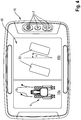
- Fig. 4 shows a running as an operating terminal 16 display device 9, which is arranged in the cabin of the tractor 1.
- the operating terminal 16 comprises a, in particular integrated, screen 18 and one or more operating elements 17.
- the screen 18 may be controllable such that it is subdivided into two separate screen sections 18a, 18b. In this way, during operation in the first driving mode of the tractor 1 in the one screen section 18a of the tractor 1 and the due to the steering angle by operating the steering device 12 adjusting direction of travel can be displayed as arrows 19.
- the other screen portion 18b shows virtual wheels 20 and their steering angle ⁇ resulting from the operation of the steering device 12.
- Fig. 5 the operator terminal 16 is shown, which shows a view of the screen 18 when the tractor 1 is operated in the second driving mode.
- On the screen 18 is a plan view of the tractor 1 is shown.
- the reference numeral 21 designates the high axis of the tractor 1, around which the tractor 1 can rotate in the second driving mode, when a steering lock is present by the operation of the steering device 12, but the tractor 1 is not accelerated simultaneously.
- Arrow 22 indicates the rotation of the tractor 1 about the vertical axis 21.
- the control of the display device 9 by the control device 5 for visualization of the steering and handling of the tractor 1 can be limited in time. For example, can be changed automatically when starting the tractor 1 in the first driving mode, so that it is ensured that the operator is brought to the current steering situation directly to the knowledge. After the transition from vehicle standstill into the driving state has taken place, the visualization can be hidden or switched off. When switching from the first drive mode to the second drive mode, the visualization can be activated automatically.
Landscapes
- Engineering & Computer Science (AREA)
- Chemical & Material Sciences (AREA)
- Combustion & Propulsion (AREA)
- Transportation (AREA)
- Mechanical Engineering (AREA)
- Automation & Control Theory (AREA)
- Steering Control In Accordance With Driving Conditions (AREA)
Claims (14)
- Véhicule agricole (1) comprenant au moins deux trains de roulement à chenilles entraînés (3) qui peuvent être commandés sur le plan de leur comportement de marche et de direction au moyen d'un équipement de commande (5), des impulsions générées par un dispositif directionnel (12) sur la base d'un braquage directionnel étant convertibles par l'équipement de commande (5) pour commander les trains de roulement à chenilles entraînés (5) d'une manière représentant le braquage directionnel, caractérisé en ce que l'équipement de commande (5) est agencé pour actionner le véhicule (1) dans au moins un premier mode de marche et un second mode de marche, dans le premier mode de marche le comportement de marche et de direction correspondant sensiblement à celui d'un véhicule à roues et, dans le second mode de marche, le comportement de marche et de direction correspondant sensiblement à celui d'un véhicule tout-chenillé, l'équipement de commande (5) étant agencé pour reproduire un braquage directionnel en fonction du mode de marche sélectionné.
- Véhicule agricole (1) selon la revendication 1, caractérisé en ce qu'un braquage directionnel est visualisable par l'intermédiaire d'un équipement d'affichage (9) commandable par l'équipement de commande (5).
- Véhicule agricole (1) selon la revendication 1 ou 2, caractérisé en ce qu'un braquage directionnel est visualisable par la représentation de roues virtuelles (20).
- Véhicule agricole (1) selon une des revendications 1 à 3, caractérisé en ce qu'un comportement de marche est visualisable au moyen de la représentation d'au moins une trace de passage virtuelle (14, 15) sur la base d'un braquage directionnel et/ou d'une accélération du véhicule (1).
- Véhicule agricole (1) selon une des revendications précédentes 2 à 4, caractérisé en ce que la visualisation s'effectue sous la forme d'une projection sur un pare-brise (13) du véhicule (1) ou sur un écran (7, 18) à l'intérieur de la cabine (4) du véhicule (1).
- Véhicule agricole (1) selon la revendication 1, caractérisé en ce que le braquage directionnel est représenté par l'intermédiaire d'au moins un équipement d'affichage mécanique (9, 11) qui est disposé sur le véhicule (1) et qui est commandable par l'intermédiaire de l'équipement de commande (5) .
- Véhicule agricole (1) selon une des revendications 1 à 5, caractérisé en ce que le rapport du braquage directionnel à reproduire au braquage directionnel détecté du volant est réglable.
- Véhicule agricole (1) selon une des revendications 2 à 6, caractérisé en ce que, en cas de fonctionnement du véhicule (1) dans le premier mode de marche, un rayon de virage minimal commandable par l'équipement de commande (5) correspond à celui d'un véhicule à roues avec un empattement qui correspond à l'empattement des roues virtuelles (20).
- Véhicule agricole (1) selon une des revendications 1 à 7, caractérisé en ce que l'équipement de commande (5) est agencé pour commander le comportement de direction en fonction d'au moins un paramètre de fonctionnement du véhicule (1) et du mode de marche sélectionné.
- Véhicule agricole (1) selon une des revendications 1 à 9, caractérisé en ce que l'équipement de commande (5) est agencé de façon qu'un mode de marche puisse être sélectionné manuellement.
- Véhicule agricole (1) selon une des revendications 1 à 9, caractérisé en ce que l'équipement de commande (5) est agencé pour basculer automatiquement dans le premier mode de marche en cas de passage dans un état de véhicule correspondant à l'arrêt du véhicule (1).
- Véhicule agricole (1) selon une des revendications 1 à 11, caractérisé en ce que l'équipement de commande (5) est agencé pour commander les trains de roulement à chenilles (3) au moyen d'un mécanisme de direction différentiel.
- Véhicule agricole (1) selon une des revendications 1 à 11, caractérisé en ce que l'équipement de commande (5) est agencé pour commander les trains de roulement à chenilles (3) indépendamment les uns des autres.
- Procédé d'actionnement d'un véhicule agricole (1), comprenant au moins deux trains de roulement à chenilles entraînés (3) qui peuvent être commandés sur le plan de leur comportement de marche et de direction au moyen d'un équipement de commande (5), des impulsions générées par un dispositif directionnel (12) sur la base d'un braquage directionnel étant convertibles par l'équipement de commande (5) pour commander les trains de roulement à chenilles entraînés (3) d'une manière représentant le braquage directionnel, caractérisé en ce que le véhicule (1) est actionné dans au moins un premier mode de marche et un second mode de marche, dans le premier mode de marche le véhicule (1) étant actionné conformément au comportement de marche et de direction sensiblement d'un véhicule à roues et, dans le second mode de marche, le véhicule (1) étant actionné conformément au comportement de marche et de direction sensiblement d'un véhicule tout-chenillé, l'équipement de commande (5) étant agencé pour reproduire un braquage directionnel en fonction du mode de marche sélectionné.
Applications Claiming Priority (1)
| Application Number | Priority Date | Filing Date | Title |
|---|---|---|---|
| DE102016106788.1A DE102016106788A1 (de) | 2016-04-13 | 2016-04-13 | Landwirtschaftliches Fahrzeug |
Publications (2)
| Publication Number | Publication Date |
|---|---|
| EP3231688A1 EP3231688A1 (fr) | 2017-10-18 |
| EP3231688B1 true EP3231688B1 (fr) | 2019-07-10 |
Family
ID=58265885
Family Applications (1)
| Application Number | Title | Priority Date | Filing Date |
|---|---|---|---|
| EP17160080.2A Active EP3231688B1 (fr) | 2016-04-13 | 2017-03-09 | Véhicule agricole |
Country Status (2)
| Country | Link |
|---|---|
| EP (1) | EP3231688B1 (fr) |
| DE (1) | DE102016106788A1 (fr) |
Family Cites Families (5)
| Publication number | Priority date | Publication date | Assignee | Title |
|---|---|---|---|---|
| WO2003026385A1 (fr) * | 2001-09-07 | 2003-04-03 | Dillon Ben N | Moissonneuse-batteuse articulee |
| US6298931B1 (en) | 1999-12-09 | 2001-10-09 | Deere & Company | Tracked vehicle steering control system with non-centered steering wheel |
| DE10033261A1 (de) * | 2000-07-11 | 2002-01-24 | Macmoter Spa | Fahrzeug |
| WO2008042244A2 (fr) * | 2006-09-29 | 2008-04-10 | Volvo Construction Equipment Ab | systÈme de direction et de propulsion pour une FRAISEUSE ROUTIÈRE |
| US20130158802A1 (en) * | 2011-12-16 | 2013-06-20 | Caterpillar Paving Products Inc. | Steering System for Crawler Track Machine |
-
2016
- 2016-04-13 DE DE102016106788.1A patent/DE102016106788A1/de not_active Withdrawn
-
2017
- 2017-03-09 EP EP17160080.2A patent/EP3231688B1/fr active Active
Non-Patent Citations (1)
| Title |
|---|
| None * |
Also Published As
| Publication number | Publication date |
|---|---|
| EP3231688A1 (fr) | 2017-10-18 |
| DE102016106788A1 (de) | 2017-10-19 |
Similar Documents
| Publication | Publication Date | Title |
|---|---|---|
| DE102006048947B4 (de) | Steuereinheit und Verfahren zum Verstellen eines an ein Fahrzeug angekuppelten Anhängers | |
| EP2388180B1 (fr) | Dispositif d'aide à la marche arrière pour le réglage de la marche arrière d'un train de véhicule automobile | |
| EP2879938B1 (fr) | Procédé et appareil pour garer un remorque | |
| DE102007029413B4 (de) | Verfahren zur Durchführung eines Lenkvorganges in einem Fahrzeug mit Anhänger bei Rückwärtsfahrt | |
| DE102016214433B4 (de) | Ablenkungsfreies Fernsteuern eines Kraftfahrzeugs mit einem Parkassistenzsystem | |
| EP2014504B1 (fr) | Dispositif de commande destiné à la commande d'au moins une taille d'état d'un véhicule utilitaire agricole ou industriel | |
| DE102012205416B4 (de) | Anhängerwegkrümmungssteuerung für Anhängerrückfahrhilfe | |
| DE102016101070B4 (de) | Anhängerrücksetzunterstützungssystem mit adaptiven lenkwinkelgrenzen | |
| DE102005004394B4 (de) | Rückfahrtassistent | |
| DE102005043467A1 (de) | Rückfahrhilfesystem zur Regelung der Rückwärtsfahrt eines Fahrzeuggespanns | |
| EP0970875B1 (fr) | Système de direction pour véhicules | |
| DE102005043466A1 (de) | Rückfahrhilfesystem und Verfahren zur Unterstützung des Fahrers eines Zugfahrzeug-Anhänger-Gespanns bei einer Rückwärtsfahrt | |
| EP3418159A2 (fr) | Procédé de fonctionnement d'un dispositif d'aide au stationnement d'un véhicule automobile à vue combinée de la remorque transparente et de l'environnement | |
| EP3959111B1 (fr) | Procédé pour faire fonctionner un système d'assistance au conducteur d'un véhicule automobile qui peut fonctionner au moins partiellement à l'électricité en vue de commander quatre roues, système d'assistance au conducteur ainsi que véhicule automobile | |
| DE102016120203A1 (de) | Beleuchteter fahrzeugsteuermanagement-drucktasten-knopf | |
| DE102016119897B4 (de) | Geschwindigkeitssteuerung für Kraftfahrzeuge | |
| DE102013000198A1 (de) | Verfahren und Vorrichtung zum Rangieren eines Anhängers | |
| EP2583544A1 (fr) | Dispositif de visulaisation | |
| DE102013016342A1 (de) | Verfahren zum assistierten Rückwärtsfahren eines Gespanns, Fahrerassistenzsystem | |
| EP2014503A1 (fr) | Dispositif de commande destiné à la commande d'au moins une taille d'état d'un véhicule utilitaire agricole ou industriel | |
| DE102013003853A1 (de) | Verfahren, Steuersystem und Bremssystem zur Steuerung des Rückwärtsrangierens eines Gespannfahrzeugs | |
| DE102016116913A1 (de) | Multifunktionsneigungsschalter für Parkfunktion | |
| EP4213132B1 (fr) | Véhicule automobile et procédé de fonctionnement d'un véhicule automobile | |
| DE102021203551A1 (de) | Fahrintentionserkennung | |
| DE102015005975B4 (de) | Verfahren zum Betrieb eines Querführungssystems eines Kraftfahrzeugs und Kraftfahrzeug |
Legal Events
| Date | Code | Title | Description |
|---|---|---|---|
| PUAI | Public reference made under article 153(3) epc to a published international application that has entered the european phase |
Free format text: ORIGINAL CODE: 0009012 |
|
| STAA | Information on the status of an ep patent application or granted ep patent |
Free format text: STATUS: THE APPLICATION HAS BEEN PUBLISHED |
|
| AK | Designated contracting states |
Kind code of ref document: A1 Designated state(s): AL AT BE BG CH CY CZ DE DK EE ES FI FR GB GR HR HU IE IS IT LI LT LU LV MC MK MT NL NO PL PT RO RS SE SI SK SM TR |
|
| AX | Request for extension of the european patent |
Extension state: BA ME |
|
| STAA | Information on the status of an ep patent application or granted ep patent |
Free format text: STATUS: REQUEST FOR EXAMINATION WAS MADE |
|
| 17P | Request for examination filed |
Effective date: 20180418 |
|
| RBV | Designated contracting states (corrected) |
Designated state(s): AL AT BE BG CH CY CZ DE DK EE ES FI FR GB GR HR HU IE IS IT LI LT LU LV MC MK MT NL NO PL PT RO RS SE SI SK SM TR |
|
| GRAP | Despatch of communication of intention to grant a patent |
Free format text: ORIGINAL CODE: EPIDOSNIGR1 |
|
| STAA | Information on the status of an ep patent application or granted ep patent |
Free format text: STATUS: GRANT OF PATENT IS INTENDED |
|
| INTG | Intention to grant announced |
Effective date: 20190411 |
|
| GRAS | Grant fee paid |
Free format text: ORIGINAL CODE: EPIDOSNIGR3 |
|
| GRAA | (expected) grant |
Free format text: ORIGINAL CODE: 0009210 |
|
| STAA | Information on the status of an ep patent application or granted ep patent |
Free format text: STATUS: THE PATENT HAS BEEN GRANTED |
|
| AK | Designated contracting states |
Kind code of ref document: B1 Designated state(s): AL AT BE BG CH CY CZ DE DK EE ES FI FR GB GR HR HU IE IS IT LI LT LU LV MC MK MT NL NO PL PT RO RS SE SI SK SM TR |
|
| REG | Reference to a national code |
Ref country code: GB Ref legal event code: FG4D Free format text: NOT ENGLISH |
|
| REG | Reference to a national code |
Ref country code: CH Ref legal event code: EP Ref country code: AT Ref legal event code: REF Ref document number: 1153280 Country of ref document: AT Kind code of ref document: T Effective date: 20190715 |
|
| REG | Reference to a national code |
Ref country code: DE Ref legal event code: R096 Ref document number: 502017001705 Country of ref document: DE |
|
| REG | Reference to a national code |
Ref country code: IE Ref legal event code: FG4D Free format text: LANGUAGE OF EP DOCUMENT: GERMAN |
|
| REG | Reference to a national code |
Ref country code: NL Ref legal event code: MP Effective date: 20190710 |
|
| REG | Reference to a national code |
Ref country code: LT Ref legal event code: MG4D |
|
| PG25 | Lapsed in a contracting state [announced via postgrant information from national office to epo] |
Ref country code: NO Free format text: LAPSE BECAUSE OF FAILURE TO SUBMIT A TRANSLATION OF THE DESCRIPTION OR TO PAY THE FEE WITHIN THE PRESCRIBED TIME-LIMIT Effective date: 20191010 Ref country code: NL Free format text: LAPSE BECAUSE OF FAILURE TO SUBMIT A TRANSLATION OF THE DESCRIPTION OR TO PAY THE FEE WITHIN THE PRESCRIBED TIME-LIMIT Effective date: 20190710 Ref country code: PT Free format text: LAPSE BECAUSE OF FAILURE TO SUBMIT A TRANSLATION OF THE DESCRIPTION OR TO PAY THE FEE WITHIN THE PRESCRIBED TIME-LIMIT Effective date: 20191111 Ref country code: LT Free format text: LAPSE BECAUSE OF FAILURE TO SUBMIT A TRANSLATION OF THE DESCRIPTION OR TO PAY THE FEE WITHIN THE PRESCRIBED TIME-LIMIT Effective date: 20190710 Ref country code: BG Free format text: LAPSE BECAUSE OF FAILURE TO SUBMIT A TRANSLATION OF THE DESCRIPTION OR TO PAY THE FEE WITHIN THE PRESCRIBED TIME-LIMIT Effective date: 20191010 Ref country code: HR Free format text: LAPSE BECAUSE OF FAILURE TO SUBMIT A TRANSLATION OF THE DESCRIPTION OR TO PAY THE FEE WITHIN THE PRESCRIBED TIME-LIMIT Effective date: 20190710 Ref country code: SE Free format text: LAPSE BECAUSE OF FAILURE TO SUBMIT A TRANSLATION OF THE DESCRIPTION OR TO PAY THE FEE WITHIN THE PRESCRIBED TIME-LIMIT Effective date: 20190710 Ref country code: FI Free format text: LAPSE BECAUSE OF FAILURE TO SUBMIT A TRANSLATION OF THE DESCRIPTION OR TO PAY THE FEE WITHIN THE PRESCRIBED TIME-LIMIT Effective date: 20190710 |
|
| PG25 | Lapsed in a contracting state [announced via postgrant information from national office to epo] |
Ref country code: AL Free format text: LAPSE BECAUSE OF FAILURE TO SUBMIT A TRANSLATION OF THE DESCRIPTION OR TO PAY THE FEE WITHIN THE PRESCRIBED TIME-LIMIT Effective date: 20190710 Ref country code: GR Free format text: LAPSE BECAUSE OF FAILURE TO SUBMIT A TRANSLATION OF THE DESCRIPTION OR TO PAY THE FEE WITHIN THE PRESCRIBED TIME-LIMIT Effective date: 20191011 Ref country code: ES Free format text: LAPSE BECAUSE OF FAILURE TO SUBMIT A TRANSLATION OF THE DESCRIPTION OR TO PAY THE FEE WITHIN THE PRESCRIBED TIME-LIMIT Effective date: 20190710 Ref country code: IS Free format text: LAPSE BECAUSE OF FAILURE TO SUBMIT A TRANSLATION OF THE DESCRIPTION OR TO PAY THE FEE WITHIN THE PRESCRIBED TIME-LIMIT Effective date: 20191110 Ref country code: RS Free format text: LAPSE BECAUSE OF FAILURE TO SUBMIT A TRANSLATION OF THE DESCRIPTION OR TO PAY THE FEE WITHIN THE PRESCRIBED TIME-LIMIT Effective date: 20190710 Ref country code: LV Free format text: LAPSE BECAUSE OF FAILURE TO SUBMIT A TRANSLATION OF THE DESCRIPTION OR TO PAY THE FEE WITHIN THE PRESCRIBED TIME-LIMIT Effective date: 20190710 |
|
| PG25 | Lapsed in a contracting state [announced via postgrant information from national office to epo] |
Ref country code: TR Free format text: LAPSE BECAUSE OF FAILURE TO SUBMIT A TRANSLATION OF THE DESCRIPTION OR TO PAY THE FEE WITHIN THE PRESCRIBED TIME-LIMIT Effective date: 20190710 |
|
| PG25 | Lapsed in a contracting state [announced via postgrant information from national office to epo] |
Ref country code: RO Free format text: LAPSE BECAUSE OF FAILURE TO SUBMIT A TRANSLATION OF THE DESCRIPTION OR TO PAY THE FEE WITHIN THE PRESCRIBED TIME-LIMIT Effective date: 20190710 Ref country code: DK Free format text: LAPSE BECAUSE OF FAILURE TO SUBMIT A TRANSLATION OF THE DESCRIPTION OR TO PAY THE FEE WITHIN THE PRESCRIBED TIME-LIMIT Effective date: 20190710 Ref country code: IT Free format text: LAPSE BECAUSE OF FAILURE TO SUBMIT A TRANSLATION OF THE DESCRIPTION OR TO PAY THE FEE WITHIN THE PRESCRIBED TIME-LIMIT Effective date: 20190710 Ref country code: PL Free format text: LAPSE BECAUSE OF FAILURE TO SUBMIT A TRANSLATION OF THE DESCRIPTION OR TO PAY THE FEE WITHIN THE PRESCRIBED TIME-LIMIT Effective date: 20190710 Ref country code: EE Free format text: LAPSE BECAUSE OF FAILURE TO SUBMIT A TRANSLATION OF THE DESCRIPTION OR TO PAY THE FEE WITHIN THE PRESCRIBED TIME-LIMIT Effective date: 20190710 |
|
| PG25 | Lapsed in a contracting state [announced via postgrant information from national office to epo] |
Ref country code: SK Free format text: LAPSE BECAUSE OF FAILURE TO SUBMIT A TRANSLATION OF THE DESCRIPTION OR TO PAY THE FEE WITHIN THE PRESCRIBED TIME-LIMIT Effective date: 20190710 Ref country code: SM Free format text: LAPSE BECAUSE OF FAILURE TO SUBMIT A TRANSLATION OF THE DESCRIPTION OR TO PAY THE FEE WITHIN THE PRESCRIBED TIME-LIMIT Effective date: 20190710 Ref country code: IS Free format text: LAPSE BECAUSE OF FAILURE TO SUBMIT A TRANSLATION OF THE DESCRIPTION OR TO PAY THE FEE WITHIN THE PRESCRIBED TIME-LIMIT Effective date: 20200224 Ref country code: CZ Free format text: LAPSE BECAUSE OF FAILURE TO SUBMIT A TRANSLATION OF THE DESCRIPTION OR TO PAY THE FEE WITHIN THE PRESCRIBED TIME-LIMIT Effective date: 20190710 |
|
| REG | Reference to a national code |
Ref country code: DE Ref legal event code: R097 Ref document number: 502017001705 Country of ref document: DE |
|
| PLBE | No opposition filed within time limit |
Free format text: ORIGINAL CODE: 0009261 |
|
| STAA | Information on the status of an ep patent application or granted ep patent |
Free format text: STATUS: NO OPPOSITION FILED WITHIN TIME LIMIT |
|
| PG2D | Information on lapse in contracting state deleted |
Ref country code: IS |
|
| 26N | No opposition filed |
Effective date: 20200603 |
|
| PG25 | Lapsed in a contracting state [announced via postgrant information from national office to epo] |
Ref country code: SI Free format text: LAPSE BECAUSE OF FAILURE TO SUBMIT A TRANSLATION OF THE DESCRIPTION OR TO PAY THE FEE WITHIN THE PRESCRIBED TIME-LIMIT Effective date: 20190710 |
|
| PG25 | Lapsed in a contracting state [announced via postgrant information from national office to epo] |
Ref country code: MC Free format text: LAPSE BECAUSE OF FAILURE TO SUBMIT A TRANSLATION OF THE DESCRIPTION OR TO PAY THE FEE WITHIN THE PRESCRIBED TIME-LIMIT Effective date: 20190710 |
|
| REG | Reference to a national code |
Ref country code: CH Ref legal event code: PL |
|
| PG25 | Lapsed in a contracting state [announced via postgrant information from national office to epo] |
Ref country code: LU Free format text: LAPSE BECAUSE OF NON-PAYMENT OF DUE FEES Effective date: 20200309 |
|
| PG25 | Lapsed in a contracting state [announced via postgrant information from national office to epo] |
Ref country code: LI Free format text: LAPSE BECAUSE OF NON-PAYMENT OF DUE FEES Effective date: 20200331 Ref country code: IE Free format text: LAPSE BECAUSE OF NON-PAYMENT OF DUE FEES Effective date: 20200309 Ref country code: CH Free format text: LAPSE BECAUSE OF NON-PAYMENT OF DUE FEES Effective date: 20200331 |
|
| GBPC | Gb: european patent ceased through non-payment of renewal fee |
Effective date: 20210309 |
|
| PG25 | Lapsed in a contracting state [announced via postgrant information from national office to epo] |
Ref country code: GB Free format text: LAPSE BECAUSE OF NON-PAYMENT OF DUE FEES Effective date: 20210309 |
|
| PG25 | Lapsed in a contracting state [announced via postgrant information from national office to epo] |
Ref country code: MT Free format text: LAPSE BECAUSE OF FAILURE TO SUBMIT A TRANSLATION OF THE DESCRIPTION OR TO PAY THE FEE WITHIN THE PRESCRIBED TIME-LIMIT Effective date: 20190710 Ref country code: CY Free format text: LAPSE BECAUSE OF FAILURE TO SUBMIT A TRANSLATION OF THE DESCRIPTION OR TO PAY THE FEE WITHIN THE PRESCRIBED TIME-LIMIT Effective date: 20190710 |
|
| PG25 | Lapsed in a contracting state [announced via postgrant information from national office to epo] |
Ref country code: MK Free format text: LAPSE BECAUSE OF FAILURE TO SUBMIT A TRANSLATION OF THE DESCRIPTION OR TO PAY THE FEE WITHIN THE PRESCRIBED TIME-LIMIT Effective date: 20190710 |
|
| REG | Reference to a national code |
Ref country code: AT Ref legal event code: MM01 Ref document number: 1153280 Country of ref document: AT Kind code of ref document: T Effective date: 20220309 |
|
| P01 | Opt-out of the competence of the unified patent court (upc) registered |
Effective date: 20230516 |
|
| PG25 | Lapsed in a contracting state [announced via postgrant information from national office to epo] |
Ref country code: AT Free format text: LAPSE BECAUSE OF NON-PAYMENT OF DUE FEES Effective date: 20220309 |
|
| PGFP | Annual fee paid to national office [announced via postgrant information from national office to epo] |
Ref country code: DE Payment date: 20260319 Year of fee payment: 10 |
|
| PGFP | Annual fee paid to national office [announced via postgrant information from national office to epo] |
Ref country code: BE Payment date: 20260319 Year of fee payment: 10 |
|
| PGFP | Annual fee paid to national office [announced via postgrant information from national office to epo] |
Ref country code: FR Payment date: 20260320 Year of fee payment: 10 |