EP3231945A1 - Schacht für unterirdisches netz - Google Patents
Schacht für unterirdisches netz Download PDFInfo
- Publication number
- EP3231945A1 EP3231945A1 EP16165530.3A EP16165530A EP3231945A1 EP 3231945 A1 EP3231945 A1 EP 3231945A1 EP 16165530 A EP16165530 A EP 16165530A EP 3231945 A1 EP3231945 A1 EP 3231945A1
- Authority
- EP
- European Patent Office
- Prior art keywords
- base
- buffer
- height
- adjustment
- ring
- Prior art date
- Legal status (The legal status is an assumption and is not a legal conclusion. Google has not performed a legal analysis and makes no representation as to the accuracy of the status listed.)
- Withdrawn
Links
- 238000009434 installation Methods 0.000 claims abstract description 37
- 239000000758 substrate Substances 0.000 claims abstract description 6
- 230000000295 complement effect Effects 0.000 claims description 11
- 238000010079 rubber tapping Methods 0.000 claims description 5
- 230000000284 resting effect Effects 0.000 claims description 3
- 230000000670 limiting effect Effects 0.000 description 11
- 230000006978 adaptation Effects 0.000 description 9
- 210000003128 head Anatomy 0.000 description 9
- 239000003651 drinking water Substances 0.000 description 5
- 235000020188 drinking water Nutrition 0.000 description 5
- 238000002955 isolation Methods 0.000 description 5
- 230000000903 blocking effect Effects 0.000 description 4
- 238000012423 maintenance Methods 0.000 description 4
- 238000012986 modification Methods 0.000 description 4
- 230000004048 modification Effects 0.000 description 4
- 241001080024 Telles Species 0.000 description 3
- 239000011248 coating agent Substances 0.000 description 3
- 238000000576 coating method Methods 0.000 description 3
- 230000006378 damage Effects 0.000 description 3
- 230000000694 effects Effects 0.000 description 3
- 239000002184 metal Substances 0.000 description 3
- 229910052751 metal Inorganic materials 0.000 description 3
- 238000005096 rolling process Methods 0.000 description 3
- 239000010426 asphalt Substances 0.000 description 2
- 239000000428 dust Substances 0.000 description 2
- 230000010354 integration Effects 0.000 description 2
- 230000001681 protective effect Effects 0.000 description 2
- 239000004576 sand Substances 0.000 description 2
- XLYOFNOQVPJJNP-UHFFFAOYSA-N water Substances O XLYOFNOQVPJJNP-UHFFFAOYSA-N 0.000 description 2
- 229910001018 Cast iron Inorganic materials 0.000 description 1
- 238000006424 Flood reaction Methods 0.000 description 1
- 241000287107 Passer Species 0.000 description 1
- 206010039203 Road traffic accident Diseases 0.000 description 1
- 240000008042 Zea mays Species 0.000 description 1
- 239000010866 blackwater Substances 0.000 description 1
- 238000010586 diagram Methods 0.000 description 1
- 238000006073 displacement reaction Methods 0.000 description 1
- 238000010410 dusting Methods 0.000 description 1
- 239000013536 elastomeric material Substances 0.000 description 1
- 230000008030 elimination Effects 0.000 description 1
- 238000003379 elimination reaction Methods 0.000 description 1
- 239000010797 grey water Substances 0.000 description 1
- 230000009545 invasion Effects 0.000 description 1
- 230000002829 reductive effect Effects 0.000 description 1
- 230000002441 reversible effect Effects 0.000 description 1
- 238000010008 shearing Methods 0.000 description 1
- 125000006850 spacer group Chemical group 0.000 description 1
- 239000000126 substance Substances 0.000 description 1
- 239000002351 wastewater Substances 0.000 description 1
Images


Classifications
-
- E—FIXED CONSTRUCTIONS
- E02—HYDRAULIC ENGINEERING; FOUNDATIONS; SOIL SHIFTING
- E02D—FOUNDATIONS; EXCAVATIONS; EMBANKMENTS; UNDERGROUND OR UNDERWATER STRUCTURES
- E02D29/00—Independent underground or underwater structures; Retaining walls
- E02D29/12—Manhole shafts; Other inspection or access chambers; Accessories therefor
- E02D29/14—Covers for manholes or the like; Frames for covers
- E02D29/1409—Covers for manholes or the like; Frames for covers adjustable in height or inclination
-
- E—FIXED CONSTRUCTIONS
- E02—HYDRAULIC ENGINEERING; FOUNDATIONS; SOIL SHIFTING
- E02D—FOUNDATIONS; EXCAVATIONS; EMBANKMENTS; UNDERGROUND OR UNDERWATER STRUCTURES
- E02D29/00—Independent underground or underwater structures; Retaining walls
- E02D29/12—Manhole shafts; Other inspection or access chambers; Accessories therefor
- E02D29/14—Covers for manholes or the like; Frames for covers
- E02D29/1427—Locking devices
Definitions
- the present invention relates to the field of manholes access to an underground network, particularly in the case of roads for example.
- the present invention relates in particular to a manhole, preferably adjustable, for closing an access duct to an underground network.
- the invention more generally relates to any type of look, such as a branching view giving access to a drinking water isolation valve, or any similar type of look or similar.
- Such a conduit or access to the underground network is generally formed under the surface of the ground, in particular under the roadway, and passes through a substrate, such as sand and / or earth for example.
- a nozzle block generally forms this duct on which the invention will be arranged, but various embodiments provide for arranging it on an old installation in the roadway, such as for example an old look or any other type of access to the underground network.
- Underground networks are known in the field, especially in the case of evacuation networks under communal roads, which are practical for evacuating rainwater and wastewater.
- this type of network is inconvenient to require, especially to carry out maintenance activities, to install manholes regularly on the traffic lanes.
- This disadvantage is generally accompanied by problems of difficulty of implementation. Indeed, by the design at the moment, the establishment of a look of roadway by the road technicians is difficult to achieve, when it comes to incorporate it into the road (eg, the macadam ). The installation of the gaze must take place before the installation of the coating (bituminous in general). It is therefore difficult for the technicians to define the convex shape of the road and the height of the bituminous mix that will have to be laid.
- the convex shape of a roadway generally has an arrow of up to 7 to 10 cm. This convex shape allows an evacuation of rainwater towards the gutters, to join one of the two networks. In addition, this convex shape makes it possible to limit the risk of an automobile traffic accident when it is raining (elimination or reduction of the aquaplaning effect).
- this solution has the disadvantage of not being reusable in case of repair of the later pavement with the initial installation, in spite of the aim sought by this solution, because the means of height adjustment are not protected against the asphalt pavement generally disposed on the pavement.
- the solution proposed in the application FR2890671 presents, on the one hand, the disadvantage of leaving a space (horizontally) between the lid or buffer and the edge of the gaze, thus not sufficiently protecting the interior against the bituminous mix, but especially to leave an offset (Vertically) between some of the inner edges of the gaze and the outer edges of the buffer, which implies a lack of residual flatness of the gaze as a whole, with respect to the roadway.
- a European standard NF EN 124 defines a class and technical constraints to respect for manholes according to their location on the roadway (class C, 250KN, for a sidewalk and class D, 400KN, for a road).
- buffer looks must be manipulated to access the underground network, without being manipulated untimely, by non-users. authorized or because of external events.
- an overpressure can be observed in the pipes of the mains drainage. This overpressure is capable of lifting the buffer from a normal roadway and therefore cause a significant risk (including falling or even suction) for users (pedestrians but also vehicles) that still circulate on the roadway.
- One of the aims of the invention is to provide a look providing improved safety for users and equipped with adjustment means in height and / or flatness of the eyes that are reliable and easy to adjust.
- the setting could be realized even after the intervention of the different machines used during a creation or repair of road, so that the eye marries as well as possible the shape of the roadway (during the initial installation or later).
- nozzle block forming said duct or on an old installation of access to said underground network and comprises at least one base, fixed on said nozzle block or the old installation, and on which at least one buffer is mounted by means of height adjustment and / or in inclination, said look being characterized in that it comprises locking means fixing said pad on the base and locking the adjustment in height and / or inclination.
- the height adjustment means comprise a thread of the buffer complementary to a thread of said base, so that the screwing of the threads makes it possible to adjust the height of the buffer with respect to said base, said locking means comprising at least one screw adapted to be screwed into said base through the buffer to immobilize the latter at the desired height for the buffer.
- the height adjustment means comprise a thread of the buffer complementary to a thread of said base, so that the screwing of the threads makes it possible to adjust the height of the buffer with respect to said base.
- said locking means comprise at least one screw that can be screwed into said base through the buffer in order to immobilize the latter at the desired height for the buffer.
- the inclination adjustment means comprise at least one inclined plane of said base and / or said buffer, so that the rotation on this inclined plane allows the inclination adjustment, said locking means comprising at least one screw adapted to be screwed through said base and / or buffer provided (s) of said inclined plane, to fix the inclination to the desired orientation.
- the height adjustment means are independent of the inclination adjustment means.
- the present invention relates to a look, for closing an access duct to an underground network.
- a conduit generally passes through a substrate (11) under the surface of the ground, in particular under a roadway (10).
- the gaze is intended to be installed on a nozzle block (12) forming said conduit or on an old installation (16) for access to said underground network.
- the sight comprises at least one base (2, 3, 32, 36) mounted on said nozzle block (12) or the old installation (16).
- On this base is mounted at least one buffer (1, 1.1), by means of height adjustment means (17, 71, 32, 1.3) and / or inclination (1.2, 2, 3, 3.1, 3.2, 29, 29.1, 29.2, 29.3, 29.4).
- the look advantageously comprises locking means (6, 23, 25, 49) fixing said pad (1, 1.1) on the base (2, 3, 36) and locking the height adjustment and / or in inclination.
- the invention thus meets the two problems of height adjustment and flatness catching mentioned in the preamble of the present application, but various embodiments can provide only a height adjustment or only a tilt adjustment. .
- some embodiments, not exclusive (and therefore combinable with the above) address the problem of lifting the lid or buffer and thus further improve the safety of users.
- the height adjustment means are elements independent of the tilt adjustment elements.
- this feature allows different heights to be adjusted for a given inclination and vice versa.
- the manhole may comprise a single base, for example a base comprising a thread (71) complementary to a thread (17, 17.1) of the buffer if the sight is provided adjustable in height, as for example represented on the Figure 4B , or not including such a thread if the view is not provided adjustable in height.
- a single base may or may not include an inclined plane for tilt adjustment.
- the fixed base can be separated into several parts. Each of these parts may comprise an inclined plane or not.
- the mobile base (2) may comprise an inclined plane, as for example represented on the figure 12A or have no inclined plane (whether the fixed base has an inclined plane or not).
- the terms "fixed” and “mobile” are used to designate the fact that it is possible to rotate the mobile base relative to the fixed base to adjust the inclination of the gaze, but it is understood that they do not necessarily mean a fixation or a freedom, because one prefers in any case to fix the elements between them to improve the safety of the users.
- the fixed base (3), or the single base (32) is preferably fixed on the nozzle block or the old installation.
- the movable base is preferably fixed to the fixed base, especially when the eventual or any adjustment (s) have been made.
- These fasteners are for example provided by fixing means known per se, for example such as screws or bolts.
- the height adjustment means (17, 71, 32, 1.3) comprise at least one thread (17) of the buffer (1, 1.2, 1.3). complementary of at least one thread (71) of said base (2, 3, 3.1, 32, 36), so that the screwing of the threads (17, 71) makes it possible to adjust the height of the buffer (1, 1.2, 1.3 ) relative to said base (2, 3, 3.1, 32, 36).
- said locking means preferably comprise at least one screw (6) adapted to be screwed into said base through the buffer to immobilize the latter at the desired height for the buffer.
- the view according to various embodiments uses the principle of closing the pad or cover, by a system or screwing principle. Screwing more or less the pad allows a height adjustment relative to the ground (eg, the floor).
- the inclination adjustment means comprises at least one inclined plane (29, 29.1, 29.2, 29.3, 29.4) of said base (2, 3, 3.1, 32, 36) and / or said buffer (1 , 1.2, 1.3), so that the rotation on this inclined plane allow inclination adjustment.
- said locking means preferably comprise at least one screw (6, 49) adapted to be screwed through said base and / or buffer provided (s) of said inclined plane, to freeze the desired inclination and / or the desired orientation of this inclination.
- the look according to various embodiments uses the principle of rotation, on at least one inclined plane, of at least two parts relative to each other, for adjusting the flatness (or inclination).
- said inclination adjustment means (1.1, 1.2, 2, 3, 3.1, 3.2, 29, 29.1, 29.2, 29.3, 29.4) comprise a substantially circular ring (1.2) whose height varies progressively over its revolution of revolution, so as to form an inclined plane (29, 29.1, 29.2, 29.3, 29.4) adapted to receive said buffer (1.1), said ring (1.2) resting on a ring (1.3) comprising the thread (17) of height adjustment of said buffer (1.1).
- screw is used here to designate the screw function but that various devices are possible, such as a bolt or any device adapted to be screwed into the buffer.
- means of locking may also not be screwed but include for example a tenon whose handling is secured by a latch or other means blocking the actuation.
- one and the same locking means locks both the adjustment in height and inclination.
- the length of the thread (17) of the pad is preferably greater than the length of the net (71) of the base for a greater adjustment stroke.
- the eye comprises a skirt (4) surrounding the parts provided with threads (17, 71) to protect them against invasion by substances that may interfere with the screwing / unscrewing of these parts, for example dust or pebbles, but especially the tarmac asphalt that is usually poured around the eyes.
- the buffer preferably comprises a projection (for example in the form of a crown) on the outer periphery of which is formed the thread (17) of the buffer.
- the base comprises a ring on the inner periphery of which is formed the net (71) of the base, with a screw thread complementary to that of the net (17) of the buffer.
- the buffer comprises a ring with an internal thread and the base comprises an external thread.
- Such an inverted configuration may possibly make it possible to dispense with a skirt (4) or to limit the necessary height.
- an outer thread for the pad is generally preferred so as not to limit the height adjustment stroke.
- the inner diameter of the base is substantially smaller. that the inside diameter of the nozzle block (12) or the old installation (16) on which (or which) the sight must be arranged, so that the inclination adjustment does not limit the height adjustment because of a possible contact between the buffer and the block nozzle (12) or installation.
- some solutions of the prior art have the disadvantage that the buffer can sometimes not be sufficiently screwed into the base because of the tilt adjustment. It is therefore provided here an adjustment of the inner and outer diameters of the various elements according to the angles of inclination and dimensions of the structures on which the eye is intended to be installed.
- an inward offset (a shift towards the center) of the portion provided with the internal thread (71) is preferably provided, so as to ensure the absence of contact between the external thread ( 17) and the underlying structures (eg, the base and the nozzle block or the old installation).
- cylindrical is used in the present description to designate annular structures, for example substantially cylindrical, with in general (but not necessarily) a variable height on their revolution revolution. This designation should not therefore be interpreted in a limiting way since it does not normally imply any limitation on the exact shape of the structure (which may have a square or rectangular cross-section for example), whereas in the case of a ring with a net, it is clear that the cylindrical shape is required.
- buffer is used here to refer to the cover of the manhole in a known manner and must not be interpreted in itself in a limiting manner and only the particular technical characteristics of the various arrangements of the buffer according to various embodiments must be considered.
- said base (2, 3, 32, 36) has, on its upper surface facing the lower surface of the pad (1, 1.1), a plurality of holes (25), distributed angularly with a determined distribution, to receive said locking screw (6) through the buffer (1, 1.1) and allow locking at different heights.
- a plurality of holes (25) distributed angularly with a determined distribution, to receive said locking screw (6) through the buffer (1, 1.1) and allow locking at different heights.
- said screw (6) comprises, at least on a proximal portion, at least one thread (22) complementary to a tapping (24) in the buffer (1).
- said screw (6) comprises, at least on a distal portion, a pin (23) complementary to a housing (25) in said base (2, 3, 32, 36). It is generally chosen that the screw is thus screwed only in the buffer, to facilitate the establishment of the locking device and limit the cost since it only has to tapped a hole (or only a few holes, d less than 6 for example) in the buffer instead of having to tap many holes in the base, since it is much preferable to have a plurality of holes in the base to facilitate adjustment at different heights.
- said tilt adjustment means (1.2, 2, 3, 3.1, 3.2, 29, 29.1, 29.2, 29.3, 29.4) comprise at least one ring gear (1.2, 2, 3, 3.1, 3.2), for example, substantially circular, whose height varies progressively over its revolution revolution, so as to form an inclined plane (29, 29.1) adapted to receive said base (2, 3, 3.1, 32, 36) or forming this base alone or in combination with another room, or adapted to receive said buffer (1, 1.1).
- said locking means (6, 23, 25, 42, 42.1, 42.2, 49) preferably comprise at least one screw (6, 49) adapted to be screwed into said ring (1.2, 2, 3, 3.1, 3.2), possibly forming, alone or in combination with another part, said base (2, 3, 32, 36) thus traversed by said screw (6, 49), or adapted to be screwed directly into said base and / or in said buffer (1, 1.1), so as to immobilize said ring (1.2, 2, 3, 3.1, 3.2) once its orientation has been determined for adjusting the inclination.
- said base (2, 3, 32, 36), comprising the height adjustment net (71), and the crown (1.2, 2, 3, 3.1, 3.2), comprising the inclined plane (29, 29.1) are formed by one and the same piece, for example as represented in an illustrative and nonlimiting manner on the Figures 4 and 5 .
- the eye comprises a second crown (1.2, 2, 3, 3.1, 3.2) whose height varies progressively along its revolution revolution so as to form an inclined plane (29, 29.1) adapted to receive said base (2, 3, 32, 36) or said buffer (1, 1.1) or the first ring (1.2, 2, 3, 3.1, 3.2).
- the tilt adjustment ring (1.2, 2, 3, 3.1, 3.2) is formed by a fixed base (3) anchored to the nozzle block (12) and receiving a movable base (2) comprising said height-adjusting net (71), for example as shown in an illustrative and nonlimiting manner on the figures 3A, 3B and the Figures 14A, 14B, 14C and 15 .
- the fixed base (3) forming the inclination adjusting ring (1.2, 2, 3, 3.1, 3.2) comprises a first ring (3.1) of constant height and a second ring (3.2) of height.
- the tilt adjustment ring (1.2, 2, 3, 3.1, 3.2) is formed by a movable base (2) comprising said height-adjusting net (71) and fixed on a fixed base ( 3) anchored to the nozzle block (12), for example as shown in an illustrative and nonlimiting manner on the figure 12A .
- the two aspects can be combined by providing an inclined mobile base for tilt adjustment and provided with the height adjustment net.
- such a mobile base can be combined with any fixed base described in the present application, whether it has an inclined plane or not.
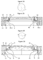
- said pad (1.1) mounted on said tilt-adjusting ring (1.2) has an inclined lower surface for further inclination adjustment, for example as shown in an illustrative and non-limiting manner on the Figures 20A, 21 and 22 .
- this type of alternative embodiment with tilt adjustment at the buffer can be combined with any another alternative embodiment of the mobile and / or fixed bases described in the present application (eg, with or without an inclined plane for tilt adjustment).
- the holes (42, 42.1, 30.2) allowing the tilt lock screw (49) to pass through the pad (1.1) and the inclined ring (1.2) must be of larger diameter than the outer diameter of this screw (49), whereas this screw has substantially the same diameter as the threaded hole (30.3) receiving the threaded distal end of this screw (49) in the threaded ring ( 71) of height adjustment.
- the intermediate ring (1.2) forming an inclined plane (29.4) and disposed between the pad (1.1), possibly also provided with an inclined plane (29.3), and the crown (1.3) of height adjustment, has an outer diameter greater than that of the crown (1.3) height adjustment and the holes (42.1) adapted to receive the security screw (6, 49) are arranged vis-à-vis the holes (20) of the buffer (1.1), so that said screw passes through the buffer and the intermediate ring to be screwed into the holes (25) of the base comprising the pitch (71) of height adjustment.
- this hole (25) will be tapped while the hole (20) of the buffer (1.1) and the hole (42.1) of the intermediate ring (1.3) are preferably smooth and of internal diameter greater than the outer diameter of the screw (6, 49), so as to facilitate the inclination adjustments (with however limited play to the maximum to limit the risk of shearing the screw).
- the screw By tapping the hole (25) of the base, the screw fixed parts between them and allows to lock both settings (height and inclination) at the same time.
- provision can be made preferably to fix the intermediate crown (1.2) of adjustment of inclination on the crown (1.3) of height adjustment before mounting the buffer on the assembly, although the figure 23 does not show such fixation.
- the buffer can have different diameters depending on the need (with a single look, to the manhole).
- Example of use for a diameter of about 20 cm, the innovation can be used as a connection point for access to the drinking water stop valve on the road, for a diameter of about 60 cm , the passage of a man for a maintenance intervention on a pipe.
- the adjustment in height, with respect to the roadway, is done by screwing more or less the buffer (1) in the mobile base (2).
- the type of screw pitch used is preferably a square screw pitch (17 and 71), which allows a high resistance to shear, thus to withstand the strong mechanical stresses generated by the rolling of a large load on it ( Standard NF EN 124), and also allows to have a large screw pitch. (The pitch of screw, will determine in mm the displacement in height of the buffer when this one makes a complete revolution).
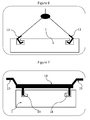
- the maneuvering of the complete manhole can be carried out using known tools or using more specific tools, an example of which is shown in the diagram. figure 6 .
- the buffer which is carried out with specific tools with lifting hooks (13) that are inserted into the two maneuvering holes (18) for a easier manual or mechanical manipulation (cf. figure 6 ).
- the screwing and unscrewing of the buffer can be carried out using a specific tool, called an operating key (14), such as a key 2 rectangular pins (19) which fit into both blind maneuvering holes (18), which are manipulated by the maneuvering handles (15).
- an operating key such as a key 2 rectangular pins (19) which fit into both blind maneuvering holes (18), which are manipulated by the maneuvering handles (15).
- Handling of the buffer can only be done by authorized personnel, a security lock is mandatory.
- Blocking in rotation (screwing / unscrewing) of the buffer is achieved by a safety screw (6) screwed into the buffer (1).
- the head of the screw (21) security is housed in a countersink (20) allowing it to not exceed the buffer (1).
- the safety screw (6) is screwed into the buffer.
- the tenon (23) of the security screw (6) is housed in one of the four holes (25) of the mobile base (2).
- the unscrewing screwing of this safety screw with a specific head (21) can only be carried out with an appropriate key as detailed with reference to the examples of the FIGS. 8A, 8B and 9A, 9B .
- an O-ring (8) is preferably placed under the screw head, guaranteeing watertightness as well as screw dusting. (22, 24), this O-ring is housed in a chamfer (27) formed at the bottom of the countersink (20).
- a bore positioned in the buffer makes it possible to adjust the pitch of the pad (2) in rotation by 1/4 turn, the finest adjustment in height being thus a quarter of the length of the thread.
- a screw for example of the CHC type, is simply screwed into the buffer, with an O-ring under the head as for the safety screw.
- the screw (for example CHC) should have a length also less than or equal to the length of the thread (24).
- a maximum unscrewing height of the buffer (1) will be imposed. This height will be limited by the number of turns of the square screw thread (17, 71) that can withstand a maximum load without destruction of the thread.
- This screw length length safety can be achieved by the length of the tenon (23) of the security screw in the mobile base (2). Indeed, it is sufficient to provide the screw with a length corresponding to the number of turns sufficient to meet the permissible load limits.
- the security screw does not lock the buffer, the person in charge of the installation will know that the maximum height of adjustment is reached and that it is then necessary to replace the buffer by another with a longer thread and associated with a longer safety screw.
- an anti-skid pattern or coating for a question of safety of road users, and particularly for a two-wheeled vehicle.
- Such a coating or pattern to prevent skidding vehicles can take different forms, ranging from the most basic to the most complex (teardrop, to the coat of arms of the city).
- Figure 8D and 9D is to reduce the thickness of the cast iron buffer (1), and replace it simply by macadam. This is simply incorporated into the buffer of the manhole during the laying of the macadam of the road.
- the 2-piece base is recommended for large diameters.
- the mobile base (2) it is she who receives by screwing the buffer (1).
- the thread (71) will have a minimum number of turns to withstand the significant shear stresses that the buffer (1) transmits.
- different type of look with different threads may be proposed depending on the location of the gaze on a sidewalk or pedestrian or on the roads.
- the communal roads having a convex shape once the manhole is positioned in the tarmac, it is impossible to perform a flatness adjustment.
- one of the four smooth holes (25) receives the tenon (23) of the security screw Figure 8C .
- a circular groove or groove (31) is provided in the upper part of the movable base (2) to receive the anti-odor seal (for example a toric multi-turn seal) (7) in order to ensure odor-tightness between the mobile base (2) and the buffer (1), Figure 8C and 9C .
- the anti-odor seal for example a toric multi-turn seal
- the mobile base (2) receives on its high part the mobile base (2), on its inclined plane (29.1, 29.2) also 2 °, once the adjustment of flatness carried out, compared to the macadam of the roadway, it is necessary to secure the two bases.
- the two bases are made integral by four screws or bolts which are inserted in the four fixing holes (30.1, 30.2, 30.3) provided for this purpose.
- a base in two parts also allows a subsequent adjustment, if after implementation in the state of the art, the base was sinking into the substrate (11) of the floor where the nozzle block (12) to move, the lack of flatness can be resumed (cf. figure 3 ).
- the fixed base (3) also receives the skirt (4).
- smooth holes (33.1, 33.2) are provided to receive screws or bolts screwed into the base (cf. Figure 14B, 14C , 18B and 18C ).
- the single-piece base (32), called a branching port, is used for access, for example, to isolation valves or a drinking water supply meter that supplies the individual. It will be used for small diameters up to 20cm in diameter of the buffer.
- the buffer (1) allows direct access to the head of the isolation valve with a specific tube wrench. On such a diameter, the gap of flatness is negligible.
- the base in one piece is reserved for tampons do not exceed 20cm, so small.
- the tightening of the 4 nuts must be accessible with a key, the block nozzle should not prevent its accessibility.
- the role of the skirt (4) is to maintain the macadam, during the laying thereof and thus to allow the rotation of the pad (1) without friction on the macadam, but also to avoid that the macadam does not come into contact with the thread (17) of the tampon (1).
- the skirt (4) is fixed by means of (for example) four tabs (34) to the fixed base (3) by four bolts introduced into the smooth holes (33, 33.1, 33.2), which must be accessible under the fixed base for tightening.
- a height adjustment of the skirt (4) is necessary, to adjust it to the height of the buffer (1) and thus the macadamized road figure 3 , especially in the case of a tilt-adjustable sight.
- the height adjustment of the skirt (4) will be done by adding a shim (5) under the brackets of the skirt (34) and to make up the inclination, it is possible to provide wedges of different height.
- a draft with an angle of 5 ° (37), allows the takeoff of it from the macadam figure 16B .
- the role of the adjustment wedge (5) is the element which serves to maintain the skirt (4) at the height of the buffer (1) so on the same plane as the macadam of the road.
- the spacer is positioned under the fastening tabs (34) of the skirt (4).
- the shim (5) may consist of a simple stack of metal washers to allow fine adjustment, of the order of 2 millimeters.
- the number of washers may vary from one leg to the other, in the case where the mobile base (2) is not parallel to the fixed base (3), in the case of a convex road.
- the role of the gasket (7) is to maintain an odor-tightness due to the gray and black water from mains drainage, this gasket is nonetheless optional, and not used for small diameters (connection of a valve isolation of drinking water).
- the seal (7) consists of a metal base in the form of a ring which will be housed in the groove (31) ( figure 2 and 3 ) of the mobile base (2). On this metal base, is bonded a ring-shaped joint assembly of elastomeric material Figure 9C . Depending on the height that is between the buffer and the movable base, one or more strands of the seal are cut to adjust this height.
- This point also has a second function which is to prevent loosening of the safety screw by the repeated vibrations of vehicles rolling on the manhole.
- a chamfer (27) has been made in the bottom of the countersink (20) of the buffer (1) to receive the O-ring (8).
- a first variant of the flatness adjustment is made on the fixed base Figure 18A or 19 .
- the fixed base (3) is now composed of two elements (3.1 and 3.2).
- a first element (3.1) remains integral with the macadam as before, and has a shoulder for receiving a ring (3.2).
- This ring (3.2) has a plane face which rests on the shoulder of the first element (3.1), and the other face forms an inclined plane, for example 2 °, to receive the mobile base (2).
- This crown by its mobility in the shoulder Figure 18B and Figure 18C , allows finer flatness adjustment than before.
- a second variant is to take this adjustment principle.
- the flatness adjustment is no longer performed on the fixed / mobile base, but on the buffer figure 20A and / or 21.
- the fixed base and the movable base become one piece. This configuration makes it possible to carry out the 2 height and flatness adjustments on a single element of the manhole.
- a chamfer (41) makes it possible to receive a spherical washer.
- This washer allows bearing during flatness adjustment, axis deviations generated between the elements (1.2 and 1.3) which are horizontal and the element (1.1) which is inclined if it must follow the curvature of the convex road.
- the device according to the invention is particularly intended to optimize the integration of manholes, in order to improve the safety of two-wheeled users and improve driving comfort for other vehicles by eliminating or at least reducing the "pothole effect", but also to reduce the maintenance costs of the traffic pavement.
Landscapes
- Engineering & Computer Science (AREA)
- Environmental & Geological Engineering (AREA)
- Life Sciences & Earth Sciences (AREA)
- General Life Sciences & Earth Sciences (AREA)
- Mining & Mineral Resources (AREA)
- Paleontology (AREA)
- Civil Engineering (AREA)
- General Engineering & Computer Science (AREA)
- Structural Engineering (AREA)
- Road Signs Or Road Markings (AREA)
Priority Applications (1)
| Application Number | Priority Date | Filing Date | Title |
|---|---|---|---|
| EP16165530.3A EP3231945A1 (de) | 2016-04-15 | 2016-04-15 | Schacht für unterirdisches netz |
Applications Claiming Priority (1)
| Application Number | Priority Date | Filing Date | Title |
|---|---|---|---|
| EP16165530.3A EP3231945A1 (de) | 2016-04-15 | 2016-04-15 | Schacht für unterirdisches netz |
Publications (1)
| Publication Number | Publication Date |
|---|---|
| EP3231945A1 true EP3231945A1 (de) | 2017-10-18 |
Family
ID=55794860
Family Applications (1)
| Application Number | Title | Priority Date | Filing Date |
|---|---|---|---|
| EP16165530.3A Withdrawn EP3231945A1 (de) | 2016-04-15 | 2016-04-15 | Schacht für unterirdisches netz |
Country Status (1)
| Country | Link |
|---|---|
| EP (1) | EP3231945A1 (de) |
Cited By (4)
| Publication number | Priority date | Publication date | Assignee | Title |
|---|---|---|---|---|
| CN108775025A (zh) * | 2018-07-06 | 2018-11-09 | 吕琛 | 一种窨井盖 |
| CN112502191A (zh) * | 2020-11-30 | 2021-03-16 | 河南富达电力集团有限公司 | 一种井口防线装置 |
| CN112922038A (zh) * | 2021-04-12 | 2021-06-08 | 李林 | 一种井盖复合结构 |
| CN113086912A (zh) * | 2021-05-10 | 2021-07-09 | 重庆公共运输职业学院 | 一种可调高度防盗窨井盖装置的专用工具及其使用方法 |
Citations (3)
| Publication number | Priority date | Publication date | Assignee | Title |
|---|---|---|---|---|
| EP0826834A2 (de) | 1996-08-30 | 1998-03-04 | Alois Pichler | Schachtabschluss |
| US5797221A (en) * | 1997-03-05 | 1998-08-25 | Young; James E. | Replacement manhole cover assembly |
| FR2890671A1 (fr) | 2005-09-15 | 2007-03-16 | Francesco Giaon | Plaque d'egout universelle pour route de type reglable |
-
2016
- 2016-04-15 EP EP16165530.3A patent/EP3231945A1/de not_active Withdrawn
Patent Citations (3)
| Publication number | Priority date | Publication date | Assignee | Title |
|---|---|---|---|---|
| EP0826834A2 (de) | 1996-08-30 | 1998-03-04 | Alois Pichler | Schachtabschluss |
| US5797221A (en) * | 1997-03-05 | 1998-08-25 | Young; James E. | Replacement manhole cover assembly |
| FR2890671A1 (fr) | 2005-09-15 | 2007-03-16 | Francesco Giaon | Plaque d'egout universelle pour route de type reglable |
Cited By (5)
| Publication number | Priority date | Publication date | Assignee | Title |
|---|---|---|---|---|
| CN108775025A (zh) * | 2018-07-06 | 2018-11-09 | 吕琛 | 一种窨井盖 |
| CN112502191A (zh) * | 2020-11-30 | 2021-03-16 | 河南富达电力集团有限公司 | 一种井口防线装置 |
| CN112922038A (zh) * | 2021-04-12 | 2021-06-08 | 李林 | 一种井盖复合结构 |
| CN113086912A (zh) * | 2021-05-10 | 2021-07-09 | 重庆公共运输职业学院 | 一种可调高度防盗窨井盖装置的专用工具及其使用方法 |
| CN113086912B (zh) * | 2021-05-10 | 2022-09-13 | 重庆公共运输职业学院 | 一种可调高度防盗窨井盖装置的专用工具及其使用方法 |
Similar Documents
| Publication | Publication Date | Title |
|---|---|---|
| CA2307755C (fr) | Dispositif de reglage d'inclinaison de surface de construction sur plot | |
| EP3231945A1 (de) | Schacht für unterirdisches netz | |
| EP2795006B1 (de) | Flussbegrenzungsvorrichtung | |
| FR2961223A1 (fr) | Ensemble d'elevation pour chambres de stockage d'eau | |
| WO2016097535A1 (fr) | Système de recouvrement et de protection de conduites ou câbles enterrés | |
| FR3027318A1 (fr) | Regard pour reseau souterrain | |
| EP2126228B1 (de) | Vorrichtung zur sicherung von hydranten durch verriegelung des schiebers eines schiebeventils | |
| FR3061501B1 (fr) | Regard pour chaussee de circulation et procede de reglage de la hauteur d'un tel regard | |
| CA2156014C (fr) | Bouche d'acces a tete flottante | |
| FR2928394A1 (fr) | Dispositif de guidage combine pour abri telescopique | |
| EP2902555B1 (de) | Anschlussteil von einer Regenwasserkanalisationsleitung, Sichtschacht für Regenwasserkanalisationsleitungen, und gesamte Kanalisationsleitung, die einen solchen Sichtschacht umfasst | |
| FR2928395A1 (fr) | Dispositif de guidage monorail pour abri telescopique | |
| FR2788069A3 (fr) | Regard de visite et d'acces a une canalisation | |
| FR3060038A1 (fr) | Dispositif de manoeuvre inviolable d'un equipement de distribution d'eau et equipement de distribution d'eau pourvu d'un tel dispositif | |
| BE1025809B1 (fr) | Regard pour chaussee de circulation et procede d'inclinaison d'un tel regard | |
| EP2431527A1 (de) | Kanaltrennelement und/oder Straßenbebakung und Kanaltrennungsbarriere | |
| FR2745841A1 (fr) | Procede et dispositif de fixation au sol d'un element de mobilier urbain et cabine telephonique comprenant un tel dispositif | |
| WO2023089270A1 (fr) | Dispositif d'accès à une infrastructure souterraine comportant une jambe de maintien en position entrouverte | |
| CA2582187A1 (en) | Adjustable manhole or utility access cover | |
| EP2843143B1 (de) | Vorrichtung zum Justieren des Flüssigkeitsspiegels in einer Leitung, und Flüssigkeitsverteilungsbehälter, der eine solche Vorrichtung umfasst | |
| FR3069039A1 (fr) | Dispositif de manœuvre a securite amelioree d'un equipement de distribution d'eau | |
| FR3025547A1 (fr) | Systeme de goulotte avec bac tampon integre pour realiser des piscines dites miroir | |
| FR3051489A1 (fr) | Procede de pose ajustee d'une couverture d'un regard d'ouvrage en chaussee et dispositif de couverture adapte | |
| FR3122888A1 (fr) | Appareillage de distribution d’eau sécurisé | |
| FR3088350A1 (fr) | Dispositif de raccordement a selecteur de debit integre pour equipement de distribution d'eau et equipement de distribution d'eau pourvu d'un tel dispositif |
Legal Events
| Date | Code | Title | Description |
|---|---|---|---|
| PUAI | Public reference made under article 153(3) epc to a published international application that has entered the european phase |
Free format text: ORIGINAL CODE: 0009012 |
|
| AK | Designated contracting states |
Kind code of ref document: A1 Designated state(s): AL AT BE BG CH CY CZ DE DK EE ES FI FR GB GR HR HU IE IS IT LI LT LU LV MC MK MT NL NO PL PT RO RS SE SI SK SM TR |
|
| AX | Request for extension of the european patent |
Extension state: BA ME |
|
| 17P | Request for examination filed |
Effective date: 20180326 |
|
| RBV | Designated contracting states (corrected) |
Designated state(s): AL AT BE BG CH CY CZ DE DK EE ES FI FR GB GR HR HU IE IS IT LI LT LU LV MC MK MT NL NO PL PT RO RS SE SI SK SM TR |
|
| GRAP | Despatch of communication of intention to grant a patent |
Free format text: ORIGINAL CODE: EPIDOSNIGR1 |
|
| INTG | Intention to grant announced |
Effective date: 20180516 |
|
| STAA | Information on the status of an ep patent application or granted ep patent |
Free format text: STATUS: THE APPLICATION IS DEEMED TO BE WITHDRAWN |
|
| 18D | Application deemed to be withdrawn |
Effective date: 20180927 |