EP3232016B1 - Procédé et appareil de réglage d'aubes variables - Google Patents
Procédé et appareil de réglage d'aubes variables Download PDFInfo
- Publication number
- EP3232016B1 EP3232016B1 EP17165334.8A EP17165334A EP3232016B1 EP 3232016 B1 EP3232016 B1 EP 3232016B1 EP 17165334 A EP17165334 A EP 17165334A EP 3232016 B1 EP3232016 B1 EP 3232016B1
- Authority
- EP
- European Patent Office
- Prior art keywords
- sync
- ring
- gas turbine
- turbine engine
- actuator
- Prior art date
- Legal status (The legal status is an assumption and is not a legal conclusion. Google has not performed a legal analysis and makes no representation as to the accuracy of the status listed.)
- Active
Links
Images


Classifications
-
- F—MECHANICAL ENGINEERING; LIGHTING; HEATING; WEAPONS; BLASTING
- F01—MACHINES OR ENGINES IN GENERAL; ENGINE PLANTS IN GENERAL; STEAM ENGINES
- F01D—NON-POSITIVE DISPLACEMENT MACHINES OR ENGINES, e.g. STEAM TURBINES
- F01D17/00—Regulating or controlling by varying flow
- F01D17/10—Final actuators
- F01D17/12—Final actuators arranged in stator parts
- F01D17/14—Final actuators arranged in stator parts varying effective cross-sectional area of nozzles or guide conduits
- F01D17/16—Final actuators arranged in stator parts varying effective cross-sectional area of nozzles or guide conduits by means of nozzle vanes
- F01D17/162—Final actuators arranged in stator parts varying effective cross-sectional area of nozzles or guide conduits by means of nozzle vanes for axial flow, i.e. the vanes turning around axes which are essentially perpendicular to the rotor centre line
-
- F—MECHANICAL ENGINEERING; LIGHTING; HEATING; WEAPONS; BLASTING
- F01—MACHINES OR ENGINES IN GENERAL; ENGINE PLANTS IN GENERAL; STEAM ENGINES
- F01D—NON-POSITIVE DISPLACEMENT MACHINES OR ENGINES, e.g. STEAM TURBINES
- F01D17/00—Regulating or controlling by varying flow
- F01D17/02—Arrangement of sensing elements
- F01D17/08—Arrangement of sensing elements responsive to condition of working-fluid, e.g. pressure
- F01D17/085—Arrangement of sensing elements responsive to condition of working-fluid, e.g. pressure to temperature
-
- F—MECHANICAL ENGINEERING; LIGHTING; HEATING; WEAPONS; BLASTING
- F04—POSITIVE - DISPLACEMENT MACHINES FOR LIQUIDS; PUMPS FOR LIQUIDS OR ELASTIC FLUIDS
- F04D—NON-POSITIVE-DISPLACEMENT PUMPS
- F04D27/00—Control, e.g. regulation, of pumps, pumping installations or pumping systems specially adapted for elastic fluids
- F04D27/02—Surge control
- F04D27/0246—Surge control by varying geometry within the pumps, e.g. by adjusting vanes
-
- F—MECHANICAL ENGINEERING; LIGHTING; HEATING; WEAPONS; BLASTING
- F04—POSITIVE - DISPLACEMENT MACHINES FOR LIQUIDS; PUMPS FOR LIQUIDS OR ELASTIC FLUIDS
- F04D—NON-POSITIVE-DISPLACEMENT PUMPS
- F04D29/00—Details, component parts, or accessories
- F04D29/40—Casings; Connections of working fluid
- F04D29/52—Casings; Connections of working fluid for axial pumps
- F04D29/54—Fluid-guiding means, e.g. diffusers
- F04D29/56—Fluid-guiding means, e.g. diffusers adjustable
- F04D29/563—Fluid-guiding means, e.g. diffusers adjustable specially adapted for elastic fluid pumps
-
- F—MECHANICAL ENGINEERING; LIGHTING; HEATING; WEAPONS; BLASTING
- F05—INDEXING SCHEMES RELATING TO ENGINES OR PUMPS IN VARIOUS SUBCLASSES OF CLASSES F01-F04
- F05D—INDEXING SCHEME FOR ASPECTS RELATING TO NON-POSITIVE-DISPLACEMENT MACHINES OR ENGINES, GAS-TURBINES OR JET-PROPULSION PLANTS
- F05D2260/00—Function
- F05D2260/50—Kinematic linkage, i.e. transmission of position
Definitions
- This disclosure relates to gas turbine engines, and more particularly to adjusting vane angles of variable vanes in a gas turbine engine.
- Gas turbine engines typically include a compressor section, a combustor section, and a turbine section.
- air is pressurized in the compressor section and is mixed with fuel and burned in the combustor section to generate hot combustion gases.
- the hot combustion gases flow through the turbine section, which extracts energy from the hot combustion gases to power the compressor section and other gas turbine engine loads.
- variable vanes may include variable vanes that are circumferentially spaced apart from each other.
- the compressor may include multiple stages of variable vanes that are axially separated from each other by rotor blades.
- the stages of variable vanes are mechanically connected to respective synchronizing rings (sync-rings) by vane arms.
- the sync-rings rotate clockwise and counterclockwise circumferentially around the compressor case to pivot the vane arms and set vane angles that optimize engine operability (e.g., preventing stalling and/or buffeting) and engine performance (e.g., maximizing thrust and/or minimizing fuel consumption).
- an actuation system drives the sync-rings.
- Variable vane actuation systems have traditionally relied on linked multistage adjustment structures that, when actuated, simultaneously adjust each of a plurality of stages of variable vanes through a shared torque box as a single point of actuation.
- adjustment of a first stage of variable vanes necessarily also adjusts the other linked stages, because as a given sync-ring is rotated in a circumferential direction around the engine, the other sync-rings are also circumferentially rotated in a pre-established proportion.
- Separate actuators have also been proposed.
- WO 2014/189574 A2 discloses a prior art variable vane control system.
- EP 2 990 613 A1 discloses a prior art rotary hydraulic actuator for variable geometry vanes.
- the invention provides a gas turbine engine as recited in claim 1.
- the first and second actuators are electric actuators.
- the second stage of variable vanes is aft of the first stage of variable vanes, and permits a smaller range of vane angle adjustment than the first stage.
- the at least one sensor includes a pressure sensor.
- the at least one sensor includes a temperature sensor.
- the at least one sensor includes a sensor situated at an inlet or an outlet of the engine section.
- the engine section is a compressor.
- the engine section is a turbine.
- the invention also provides a method for adjusting variable vanes of a gas turbine engine as recited in claim 7.
- each actuator is an electrical actuator
- controlling each actuator to rotate its associated sync-ring comprises applying a voltage to the actuator
- the second stage of variable vanes is aft of the first stage of variable vanes, and permits a smaller range of vane angle adjustment than the first stage.
- obtaining sensor data that indicates a condition of the gas turbine engine comprises measuring a pressure of the gas turbine engine.
- obtaining sensor data that indicates a condition of the gas turbine engine comprises measuring a temperature of the gas turbine engine.
- obtaining sensor data that indicates a condition of the gas turbine engine comprises performing a measurement at an inlet or an outlet of the engine section.
- the engine section is a compressor or a turbine.
- FIG. 1 schematically illustrates a gas turbine engine 20.
- the gas turbine engine 20 is disclosed herein as a two-spool turbofan that generally incorporates a fan section 22, a compressor section 24, a combustor section 26 and a turbine section 28.
- Alternative engines might include an augmentor section (not shown) among other systems or features.
- the fan section 22 drives air along a bypass flow path B in a bypass duct defined within a nacelle 15, while the compressor section 24 drives air along a core flow path C for compression and communication into the combustor section 26 then expansion through the turbine section 28.
- the exemplary engine 20 generally includes a low speed spool 30 and a high speed spool 32 mounted for rotation about an engine central longitudinal axis A relative to an engine static structure 36 via several bearing systems 38. It should be understood that various bearing systems 38 at various locations may alternatively or additionally be provided, and the location of bearing systems 38 may be varied as appropriate to the application.
- the low speed spool 30 generally includes an inner shaft 40 that interconnects a fan 42, a first (or low) pressure compressor 44 and a first (or low) pressure turbine 46.
- the inner shaft 40 is connected to the fan 42 through a speed change mechanism, which in exemplary gas turbine engine 20 is illustrated as a geared architecture 48 to drive the fan 42 at a lower speed than the low speed spool 30.
- the high speed spool 32 includes an outer shaft 50 that interconnects a second (or high) pressure compressor 52 and a second (or high) pressure turbine 54.
- a combustor 56 is arranged in exemplary gas turbine 20 between the high pressure compressor 52 and the high pressure turbine 54.
- a mid-turbine frame 57 of the engine static structure 36 is arranged generally between the high pressure turbine 54 and the low pressure turbine 46.
- the mid-turbine frame 57 further supports bearing systems 38 in the turbine section 28.
- the inner shaft 40 and the outer shaft 50 are concentric and rotate via bearing systems 38 about the engine central longitudinal axis A which is collinear with their longitudinal axes.
- the core airflow is compressed by the low pressure compressor 44 then the high pressure compressor 52, mixed and burned with fuel in the combustor 56, then expanded over the high pressure turbine 54 and low pressure turbine 46.
- the mid-turbine frame 57 includes airfoils 59 which are in the core airflow path C.
- the turbines 46, 54 rotationally drive the respective low speed spool 30 and high speed spool 32 in response to the expansion.
- gear system 48 may be located aft of combustor section 26 or even aft of turbine section 28, and fan section 22 may be positioned forward or aft of the location of gear system 48.
- the engine 20 in one example is a high-bypass geared aircraft engine.
- the engine 20 bypass ratio is greater than about six (6), with an example embodiment being greater than about ten (10)
- the geared architecture 48 is an epicyclic gear train, such as a planetary gear system or other gear system, with a gear reduction ratio of greater than about 2.3
- the low pressure turbine 46 has a pressure ratio that is greater than about five.
- the engine 20 bypass ratio is greater than about ten (10:1)
- the fan diameter is significantly larger than that of the low pressure compressor 44
- the low pressure turbine 46 has a pressure ratio that is greater than about five 5:1.
- Low pressure turbine 46 pressure ratio is pressure measured prior to inlet of low pressure turbine 46 as related to the pressure at the outlet of the low pressure turbine 46 prior to an exhaust nozzle.
- the geared architecture 48 may be an epicycle gear train, such as a planetary gear system or other gear system, with a gear reduction ratio of greater than about 2.3:1. It should be understood, however, that the above parameters are only exemplary of one embodiment of a geared architecture engine and that the present invention is applicable to other gas turbine engines including direct drive turbofans.
- the fan section 22 of the engine 20 is designed for a particular flight condition -- typically cruise at about 0.8 Mach and about 35,000 feet (10,668 meters).
- the flight condition of 0.8 Mach and 35,000 ft (10,668 meters), with the engine at its best fuel consumption - also known as "bucket cruise Thrust Specific Fuel Consumption ('TSFC')" - is the industry standard parameter of lbm of fuel being burned divided by lbf of thrust the engine produces at that minimum point.
- "Low fan pressure ratio” is the pressure ratio across the fan blade alone, without a Fan Exit Guide Vane (“FEGV”) system.
- the low fan pressure ratio as disclosed herein according to one non-limiting embodiment is less than about 1.45.
- the "Low corrected fan tip speed” as disclosed herein according to one non-limiting embodiment is less than about 1150 ft / second (350.5 meters/second).
- Fig. 2 illustrates a schematic, cross-sectional view of an engine section 60 that includes a plurality of stages 62 of variable stator vanes 64 that extend radially outward from engine central longitudinal axis A, and are axially separated by rotor blades 66.
- the engine section 60 may be part of the low pressure compressor 44, high pressure compressor 52, low pressure turbine 46, or high pressure turbine 54, for example.
- a case 68 surrounds the engine section 60.
- variable vanes 64 are mechanically linked to sync-rings 70 that are situated outside of the case 68.
- a plurality of electric actuators 80 include respective gears 88 that engage the sync-rings 70, causing the sync-rings 70 to rotate circumferentially about the case 68. In this configuration, the gears 88 act as racks and the sync-rings 70 act as pinions.
- the sync-rings 70 also engage vane gears 102 to adjust the vane angles of variable vanes 64.
- the vane gears 102 are connected to the variable vanes 64 via extensions 74.
- variable vanes 64 Circumferential rotation of the sync-rings 70 about the case 68 causes the variable vanes 64 (and their extensions 74) to pivot, and thereby change the vane angles of the variable vanes 64.
- Each variable vane 64 has a respective inner trunnion 75 and outer trunnion 77 that guide rotation of their associated variable vane 64.
- rotation of the sync-ring 70A adjusts vane angles of the first stage 62A of variable vanes 64
- rotation of sync-ring 70B adjusts vane angles of the second stage 62B of variable vanes 64.
- the sync-rings 70A-B are actuated by their own respective actuators 80A-B, enabling the sync-rings 70A-B to be rotated independently of each other. Additional stages 62 of variable vanes (not shown) may also be included, and may also include their own respective sync-rings 70 and actuators 80 (which may also be electric).
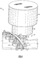
- a perspective view of the engine section 60, sync-rings 70, and actuators 80 of engine section 60 is provided in Fig. 3 .
- a controller 78 is operatively connected to at least one sensor 81 that is configured to measure a condition of the gas turbine engine 20, such as pressure or temperature.
- Fig. 2 depicts three example locations for sensors 81A-C.
- sensor 81A is situated at an inlet of the engine section 60 (e.g., an inlet of low pressure compressor 44 or high pressure compressor 52).
- sensor 81C is situated at an outlet of the engine section 60 (e.g., an outlet of low pressure compressor 44 or high pressure compressor 52).
- Sensor 81B is situated at an intermediate location between the stages 62A-B of variable vanes 64. Any one of these sensor locations may be used either alone, or in any combination. Of course, it is also understood that other sensor locations could be used.
- the controller 78 is also operatively connected to the actuators 80A-B, which as discussed above may be electric actuators.
- the controller 78 is configured to use the actuators 80A-B to rotate the sync-rings 70A-B independently of each other based on data from the at least one sensor 81. Incorporating a separate actuator 80 for each stage 62 of variable vanes 64 enables independent angle adjustment of each stage 62.
- the controller 78 includes control logic for optimizing the operating angle of each stage 62 of variable vanes 64 as the gas turbine engine 20 operates. In some embodiments, use of electric actuators 80 rather than hydraulic actuators may provide for more accurate control of the vane angles of the variable vanes 64.
- the feedback from sensor(s) 81 could be used to fine tune angle adjustments based on actual engine operating conditions, instead of constraining relative vane angles based on predicted conditions of a gas turbine engine.
- Omission of the multi-stage linkage of the prior art coupled with the use of independent adjustment of different stages of variable vanes may in some embodiments also provide increased stability for the engine section 60, decreased engine weight, and/or decreased fuel consumption.
- the various stages 62 of variable vanes 64 have different ranges of rotation, such that stages 62 closer to a fore side of the engine section 60 have a greater range of possible vane angles than stages 62 closer to an aft side of the engine section 60.
- stages 62 closer to a fore side of the engine section 60 have a greater range of possible vane angles than stages 62 closer to an aft side of the engine section 60.
- different ones of the variable vanes 62 in an engine section may have different roles (e.g., a foremost inlet vane stage 62 may have greater control over the volume of air that is communicated to the combustor, whereas later stages 62 have less control over air volume).
- the independent actuator arrangement described above can accommodate such varying ranges without requiring the prior art linkages that would otherwise be used to dependently co-rotate the sync-rings 70 with each other.
- the example sensor locations shown for the sensors 81A-C could be used individually or in any combination.
- multiple sensors 81 could be used at multiple locations and/or to measure different parameters.
- pressure and temperature are only non-limiting example parameters that could be measured.
- one or more of the sensors 81 is a major station probe (e.g., situated at station 2.5 or station 3.0).
- an engine section may include a single stage of variable vanes that use the sync-ring configuration depicted in Figs. 2-3 , and may also include one or more stages of vanes that are fixed and non-variable.
- Fig. 4 schematically illustrates a portion of Fig. 3 in greater detail.
- the actuator 80 includes an electric motor 84, reduction gear 86, and actuator gear 88.
- the reduction gear 86 permits actuator gear 88 to rotate at a lower rotational speed but a higher torque than the electric motor 84.
- the actuator gear 88 includes gear teeth 90.
- the sync-ring 70 includes a first side 92 from which first gear teeth 94 extend, and also includes an opposite, second side 96 from which gear teeth 98 extend.
- the first gear teeth 94 engage the gear teeth 90 of the actuator gear 88, in a rack and pinion configuration.
- the second gear teeth 98 engage gear teeth 100 of vane gears 102.
- Rotation of the electric motor 84 drives rotation of actuator gear 88, which rotates sync-ring 70 and vane gears 102.
- the quantity of gear teeth 100 included in a given vane gear 102 could be selected based on how much rotation of its corresponding vane is desired (e.g., more gear teeth at a foremost stage to permit greater rotation, and less gear teeth at an aft stage to permit less rotation).
- Fig. 5 is a flowchart of a method 200 for adjusting variable vanes 64 of a gas turbine engine 20.
- Sensor data is obtained (block 202) that indicates a condition of the gas turbine engine 20.
- the condition is a temperature or pressure of the engine and/or its components (e.g., the low pressure compressor 44, high pressure compressor 52, low pressure turbine 46, or high pressure turbine 54, or a combination thereof).
- a first sync-ring 70 is moved independently of a different, second sync-ring 70 (block 204).
- the first and second sync-rings 70 are part of an engine section 60 that comprises a plurality of stages 62 of variable vanes 64, wherein movement of the first sync-ring 70 adjusts vane angles of a first one of the stages 62 of variable vanes 64, and movement of the second sync-ring 70 adjusts vane angles of a second one of the stages 62 of variable vanes 64.
- additional sensor data may be obtained that indicates a condition of the gas turbine engine (block 206), and that additional sensor data may be compared to prior sensor data. Blocks 204-206 may then be iteratively repeated to perform a continuous optimization of vane angles.
- the "prior sensor data" of block 206 may include the sensor data from block 202, for example, and/or may include historical sensor data obtained in a test environment from a different gas turbine engine.
Landscapes
- Engineering & Computer Science (AREA)
- Mechanical Engineering (AREA)
- General Engineering & Computer Science (AREA)
- Physics & Mathematics (AREA)
- Geometry (AREA)
- Control Of Turbines (AREA)
- Structures Of Non-Positive Displacement Pumps (AREA)
Claims (13)
- Moteur à turbine à gaz (20) comprenant :une section de moteur (60) comprenant une pluralité d'étages (62A, B) d'aubes variables (64) ;des premier et second anneaux de synchronisation (anneaux sync) (70 ; 70A, B), dans lequel le mouvement du premier anneau sync (70A) ajuste des angles d'aube d'un premier des étages (62A) d'aubes variables (64), et le mouvement du second anneau sync (70B) ajuste des angles d'aube d'un second des étages (62B) d'aubes variables (64) ;au moins un capteur (81A-C) configuré pour mesurer un état du moteur à turbine à gaz ;un dispositif de commande (78) configuré pour déplacer le premier anneau sync (70A) indépendamment du second anneau sync (70B) sur la base de données de l'au moins un capteur (81A-C) ;un premier actionneur (80A) configuré pour faire tourner le premier anneau sync (70A), et un second actionneur différent (80B) configuré pour faire tourner le second anneau sync (70B) ;dans lequel pour déplacer le premier anneau sync (70A) indépendamment du second anneau sync (70B), le dispositif de commande (78) est configuré pour actionner le premier actionneur (80A) indépendamment du second actionneur (80B) ;caractérisé en ce que :
chaque anneau sync (70) comprend :des premières dents d'engrenage (94) situées sur un premier côté (92) de l'anneau sync (70) qui mettent en prise un engrenage d'actionneur (88) de l'actionneur (80) ; etdes secondes dents d'engrenage (98) situées sur un second côté opposé (96) de l'anneau sync (70) qui mettent en prise des engrenages d'aube (102) de l'étage (62) des aubes variables (64) associées à l'anneau sync (70). - Moteur à turbine à gaz selon la revendication 1,
dans lequel les premier et second actionneurs (80A, B) sont des actionneurs électriques. - Moteur à turbine à gaz selon la revendication 1 ou 2,
dans lequel le second étage (62B) d'aubes variables (64) est à l'arrière du premier étage (62A) d'aubes variables (64), et permet une plage plus petite d'ajustement d'angle d'aube que le premier étage (62A). - Moteur à turbine à gaz selon une quelconque revendication précédente, dans lequel l'au moins un capteur (81A-C) inclut un capteur de pression.
- Moteur à turbine à gaz selon une quelconque revendication précédente, dans lequel l'au moins un capteur (81A-C) inclut un capteur de température.
- Moteur à turbine à gaz selon une quelconque revendication précédente, dans lequel l'au moins un capteur (81A-C) inclut un capteur (81A-C) situé sur une entrée ou une sortie de la section de moteur (60).
- Procédé pour l'ajustement d'aubes variables (64) d'un moteur à turbine à gaz (20) comprenant :l'obtention de données de capteur qui indiquent un état du moteur à turbine à gaz (20) ; etle déplacement d'un premier anneau de synchronisation (anneau sync) (70A) indépendamment d'un second anneau sync (70B) sur la base de données de capteur ;dans lequel les premier et second anneaux sync (70A, B) font partie d'une section de moteur (60) qui comprend une pluralité d'étages (62A, B) d'aubes variables (64), dans lequel le mouvement du premier anneau sync (70A) ajuste des angles d'aube d'un premier des étages (62A) d'aubes variables (64), et dans lequel le mouvement du second anneau sync (70B) ajuste des angles d'aube d'un second des étages (62B) d'aubes variables (64) ;dans lequel ledit déplacement du premier anneau sync (70A) indépendamment du second anneau sync (70B) comprend : la rotation du premier anneau sync (70A) indépendamment du second anneau sync (70B) ;la commande d'un premier actionneur (80A) pour faire tourner le premier anneau sync (70A) indépendamment d'un second actionneur (80B) qui est configuré pour faire tourner le second anneau sync (70B) ; et la rotation d'un engrenage d'actionneur (88) qui met en prise des premières dents d'engrenage (94) situées sur un premier côté (92) de l'anneau sync (70), et ainsi fait tourner à la fois l'anneau sync (70) et des engrenages d'aube (102) qui mettent en prise des secondes dents d'engrenage (98) sur un second côté opposé (96) de l'anneau sync (70).
- Procédé selon la revendication 7, dans lequel chaque actionneur (80A, B) est un actionneur électrique, et la commande de chaque actionneur (80A, B) pour faire tourner son anneau sync associé (70A, B) comprend l'application d'une tension à l'actionneur (80A, B).
- Procédé selon la revendication 7 ou 8, dans lequel le second étage (62B) d'aubes variables (64) est à l'arrière du premier étage (62A) d'aubes variables (64), et permet une plus petite plage d'ajustement d'angle d'aube que le premier étage (62A).
- Procédé selon l'une quelconque des revendications 7 à 9, dans lequel l'obtention de données de capteur qui indiquent un état du moteur à turbine à gaz (20) comprend la mesure d'une pression du moteur à turbine à gaz (20).
- Procédé selon l'une quelconque des revendications 7 à 10, dans lequel l'obtention de données de capteur qui indiquent un état du moteur à turbine à gaz (20) comprend la mesure d'une température du moteur à turbine à gaz (20).
- Procédé selon l'une quelconque des revendications 7 à 11, dans lequel l'obtention de données de capteur qui indiquent un état du moteur à turbine à gaz (20) comprend la réalisation d'une mesure sur une entrée ou une sortie de la section de moteur (60).
- Moteur à turbine à gaz ou procédé selon une quelconque revendication précédente, dans lequel la section de moteur (60) est un compresseur (44, 52) ou une turbine (46, 54).
Applications Claiming Priority (1)
| Application Number | Priority Date | Filing Date | Title |
|---|---|---|---|
| US15/095,640 US10358934B2 (en) | 2016-04-11 | 2016-04-11 | Method and apparatus for adjusting variable vanes |
Publications (2)
| Publication Number | Publication Date |
|---|---|
| EP3232016A1 EP3232016A1 (fr) | 2017-10-18 |
| EP3232016B1 true EP3232016B1 (fr) | 2019-09-18 |
Family
ID=58501317
Family Applications (1)
| Application Number | Title | Priority Date | Filing Date |
|---|---|---|---|
| EP17165334.8A Active EP3232016B1 (fr) | 2016-04-11 | 2017-04-06 | Procédé et appareil de réglage d'aubes variables |
Country Status (2)
| Country | Link |
|---|---|
| US (1) | US10358934B2 (fr) |
| EP (1) | EP3232016B1 (fr) |
Families Citing this family (12)
| Publication number | Priority date | Publication date | Assignee | Title |
|---|---|---|---|---|
| US11073160B2 (en) * | 2016-09-08 | 2021-07-27 | The United States Of America As Represented By The Secretary Of The Army | Adaptable articulating axial-flow compressor/turbine rotor blade |
| BE1024982B1 (fr) * | 2017-02-09 | 2018-09-10 | Safran Aero Boosters Sa | Compresseur de turbomachine avec aubes a calage variable |
| US10644630B2 (en) | 2017-11-28 | 2020-05-05 | General Electric Company | Turbomachine with an electric machine assembly and method for operation |
| US11168578B2 (en) * | 2018-09-11 | 2021-11-09 | Pratt & Whitney Canada Corp. | System for adjusting a variable position vane in an aircraft engine |
| US11248789B2 (en) | 2018-12-07 | 2022-02-15 | Raytheon Technologies Corporation | Gas turbine engine with integral combustion liner and turbine nozzle |
| US10815802B2 (en) * | 2018-12-17 | 2020-10-27 | Raytheon Technologies Corporation | Variable vane assemblies configured for non-axisymmetric actuation |
| US11773744B2 (en) * | 2021-01-29 | 2023-10-03 | The Boeing Company | Systems and methods for controlling vanes of an engine of an aircraft |
| PL437817A1 (pl) | 2021-05-07 | 2022-11-14 | General Electric Company | Układ o zmiennej geometrii i działaniu rozdzielonym do sprężarki silnika turbinowego |
| US11560810B1 (en) * | 2021-07-20 | 2023-01-24 | Rolls-Royce North American Technologies Inc. | Variable vane actuation system and method for gas turbine engine performance management |
| US12480449B2 (en) | 2022-08-22 | 2025-11-25 | General Electric Company | Propulsion system including an electric machine for starting a gas turbine engine |
| US12270309B2 (en) * | 2022-10-21 | 2025-04-08 | Rolls-Royce North American Technologies Inc. | Variable stator vane assembly with magnetic actuation rotor for gas turbine engines |
| CN116146537A (zh) * | 2023-03-24 | 2023-05-23 | 中国航发沈阳发动机研究所 | 一种航空发动机可调静子叶片调节机构及其装配方法 |
Citations (1)
| Publication number | Priority date | Publication date | Assignee | Title |
|---|---|---|---|---|
| FR2914944A1 (fr) * | 2007-04-13 | 2008-10-17 | Snecma Sa | Calage variable d'aubes de compresseur dans une turbomachine |
Family Cites Families (24)
| Publication number | Priority date | Publication date | Assignee | Title |
|---|---|---|---|---|
| US3632224A (en) * | 1970-03-02 | 1972-01-04 | Gen Electric | Adjustable-blade turbine |
| US4279568A (en) | 1978-10-16 | 1981-07-21 | United Technologies Corporation | Vane angle control |
| US5152668A (en) * | 1990-07-23 | 1992-10-06 | General Electric Company | Pitch change mechanism for prop fans |
| GB9511269D0 (en) * | 1995-06-05 | 1995-08-02 | Rolls Royce Plc | Variable angle vane arrays |
| US5993152A (en) * | 1997-10-14 | 1999-11-30 | General Electric Company | Nonlinear vane actuation |
| GB2402180B (en) | 2003-05-30 | 2006-09-20 | Rolls Royce Plc | Variable stator vane actuating levers |
| GB0416888D0 (en) * | 2004-07-29 | 2004-09-01 | Rolls Royce Plc | Controlling a plurality of devices |
| US7588415B2 (en) | 2005-07-20 | 2009-09-15 | United Technologies Corporation | Synch ring variable vane synchronizing mechanism for inner diameter vane shroud |
| JP4699130B2 (ja) * | 2005-08-03 | 2011-06-08 | 三菱重工業株式会社 | ガスタービンの入口案内翼制御装置 |
| US20100260591A1 (en) | 2007-06-08 | 2010-10-14 | General Electric Company | Spanwise split variable guide vane and related method |
| US8240983B2 (en) * | 2007-10-22 | 2012-08-14 | United Technologies Corp. | Gas turbine engine systems involving gear-driven variable vanes |
| GB0813413D0 (en) * | 2008-07-23 | 2008-08-27 | Rolls Royce Plc | A compressor variable stator vane arrangement |
| US8534996B1 (en) * | 2008-09-15 | 2013-09-17 | Florida Turbine Technologies, Inc. | Vane segment tip clearance control |
| US7922445B1 (en) | 2008-09-19 | 2011-04-12 | Florida Turbine Technologies, Inc. | Variable inlet guide vane with actuator |
| US20120134783A1 (en) | 2010-11-30 | 2012-05-31 | General Electric Company | System and method for operating a compressor |
| US8909454B2 (en) * | 2011-04-08 | 2014-12-09 | General Electric Company | Control of compression system with independently actuated inlet guide and/or stator vanes |
| GB201202383D0 (en) * | 2012-02-13 | 2012-03-28 | Rolls Royce Plc | A unison ring gear assembly |
| EP2971598B1 (fr) | 2013-03-13 | 2019-08-21 | United Technologies Corporation | Système de commande d'aubes à incidence variable |
| US9129398B2 (en) | 2013-03-15 | 2015-09-08 | Qualcomm Incorporated | Edgel sampling for edge-based tracking |
| WO2015030858A2 (fr) * | 2013-04-08 | 2015-03-05 | United Technologies Corporation | Système de commande d'écoulement d'air annulaire à engrenages pour moteurs à turbine à gaz à cycle variable |
| EP3907374B1 (fr) * | 2013-08-21 | 2025-05-28 | RTX Corporation | Agencement de turbine à zone variable avec modulation d'écoulement secondaire |
| US10012102B2 (en) * | 2014-02-21 | 2018-07-03 | United Technologies Corporation | Variable vane synchronization ring transmission mechanism |
| US10001066B2 (en) | 2014-08-28 | 2018-06-19 | General Electric Company | Rotary actuator for variable geometry vanes |
| US10190599B2 (en) * | 2016-03-24 | 2019-01-29 | United Technologies Corporation | Drive shaft for remote variable vane actuation |
-
2016
- 2016-04-11 US US15/095,640 patent/US10358934B2/en active Active
-
2017
- 2017-04-06 EP EP17165334.8A patent/EP3232016B1/fr active Active
Patent Citations (1)
| Publication number | Priority date | Publication date | Assignee | Title |
|---|---|---|---|---|
| FR2914944A1 (fr) * | 2007-04-13 | 2008-10-17 | Snecma Sa | Calage variable d'aubes de compresseur dans une turbomachine |
Also Published As
| Publication number | Publication date |
|---|---|
| US10358934B2 (en) | 2019-07-23 |
| EP3232016A1 (fr) | 2017-10-18 |
| US20170292400A1 (en) | 2017-10-12 |
Similar Documents
| Publication | Publication Date | Title |
|---|---|---|
| EP3232016B1 (fr) | Procédé et appareil de réglage d'aubes variables | |
| EP2971598B1 (fr) | Système de commande d'aubes à incidence variable | |
| EP3536912B1 (fr) | Système d'actionnement de vanne profilée à levier coudé | |
| US10132191B2 (en) | Variable area turbine arrangement with secondary flow modulation | |
| EP2956631B1 (fr) | Système de réglage d'aubes variable | |
| EP2809926B1 (fr) | Planification d'une aube fixe à incidence variable sur la base de conditions de vol en cas de mauvais temps | |
| EP2998522B1 (fr) | Aube de stator variable de moteur de turbine | |
| US10060286B2 (en) | Geared annular airflow actuation system for variable cycle gas turbine engines | |
| EP2904218B1 (fr) | Compresseur basse pression présentant des aubes variables | |
| EP3623584B1 (fr) | Définition de l'espace de vis de réglage entre des aubes fixes et variables | |
| EP3232017B1 (fr) | Ensemble de mesure de déformation de nacelle | |
| EP3617460B1 (fr) | Système à double soupape doté de géométries de disques de soupapes différentes | |
| WO2014150489A1 (fr) | Moteur à turbine à gaz produisant un faible bruit de soufflante | |
| EP3296548B1 (fr) | Échangeur de chaleur pour turbine à gaz monté dans un capot intermédiaire | |
| EP3470656B1 (fr) | Passage de dérivation modulé de chambre de combustion | |
| EP3052769B1 (fr) | Rotors de compresseur et de turbine à mouvement de translation permettant la régulation du jeu | |
| EP3508790B1 (fr) | Moteur de turbine à gaz avec dérivation modulée de chambre de combustion et soupape de dérivation de chambre de combustion | |
| EP3385508B1 (fr) | Ensemble de levier coudé pour moteur de turbine à gaz et procédé associé | |
| EP3693576B1 (fr) | Agencement de soupape pour un système de carburant | |
| EP3460226B1 (fr) | Revêtement mobile de bouchon d'échappement |
Legal Events
| Date | Code | Title | Description |
|---|---|---|---|
| PUAI | Public reference made under article 153(3) epc to a published international application that has entered the european phase |
Free format text: ORIGINAL CODE: 0009012 |
|
| STAA | Information on the status of an ep patent application or granted ep patent |
Free format text: STATUS: THE APPLICATION HAS BEEN PUBLISHED |
|
| AK | Designated contracting states |
Kind code of ref document: A1 Designated state(s): AL AT BE BG CH CY CZ DE DK EE ES FI FR GB GR HR HU IE IS IT LI LT LU LV MC MK MT NL NO PL PT RO RS SE SI SK SM TR |
|
| AX | Request for extension of the european patent |
Extension state: BA ME |
|
| STAA | Information on the status of an ep patent application or granted ep patent |
Free format text: STATUS: REQUEST FOR EXAMINATION WAS MADE |
|
| 17P | Request for examination filed |
Effective date: 20180417 |
|
| RBV | Designated contracting states (corrected) |
Designated state(s): AL AT BE BG CH CY CZ DE DK EE ES FI FR GB GR HR HU IE IS IT LI LT LU LV MC MK MT NL NO PL PT RO RS SE SI SK SM TR |
|
| RIC1 | Information provided on ipc code assigned before grant |
Ipc: F01D 17/16 20060101AFI20190205BHEP Ipc: F01D 17/08 20060101ALI20190205BHEP Ipc: F04D 27/02 20060101ALI20190205BHEP Ipc: F04D 29/56 20060101ALI20190205BHEP |
|
| GRAP | Despatch of communication of intention to grant a patent |
Free format text: ORIGINAL CODE: EPIDOSNIGR1 |
|
| STAA | Information on the status of an ep patent application or granted ep patent |
Free format text: STATUS: GRANT OF PATENT IS INTENDED |
|
| INTG | Intention to grant announced |
Effective date: 20190402 |
|
| GRAS | Grant fee paid |
Free format text: ORIGINAL CODE: EPIDOSNIGR3 |
|
| GRAA | (expected) grant |
Free format text: ORIGINAL CODE: 0009210 |
|
| STAA | Information on the status of an ep patent application or granted ep patent |
Free format text: STATUS: THE PATENT HAS BEEN GRANTED |
|
| AK | Designated contracting states |
Kind code of ref document: B1 Designated state(s): AL AT BE BG CH CY CZ DE DK EE ES FI FR GB GR HR HU IE IS IT LI LT LU LV MC MK MT NL NO PL PT RO RS SE SI SK SM TR |
|
| REG | Reference to a national code |
Ref country code: GB Ref legal event code: FG4D |
|
| REG | Reference to a national code |
Ref country code: CH Ref legal event code: EP |
|
| REG | Reference to a national code |
Ref country code: DE Ref legal event code: R096 Ref document number: 602017007088 Country of ref document: DE |
|
| REG | Reference to a national code |
Ref country code: AT Ref legal event code: REF Ref document number: 1181550 Country of ref document: AT Kind code of ref document: T Effective date: 20191015 |
|
| REG | Reference to a national code |
Ref country code: IE Ref legal event code: FG4D |
|
| REG | Reference to a national code |
Ref country code: NL Ref legal event code: MP Effective date: 20190918 |
|
| PG25 | Lapsed in a contracting state [announced via postgrant information from national office to epo] |
Ref country code: FI Free format text: LAPSE BECAUSE OF FAILURE TO SUBMIT A TRANSLATION OF THE DESCRIPTION OR TO PAY THE FEE WITHIN THE PRESCRIBED TIME-LIMIT Effective date: 20190918 Ref country code: LT Free format text: LAPSE BECAUSE OF FAILURE TO SUBMIT A TRANSLATION OF THE DESCRIPTION OR TO PAY THE FEE WITHIN THE PRESCRIBED TIME-LIMIT Effective date: 20190918 Ref country code: BG Free format text: LAPSE BECAUSE OF FAILURE TO SUBMIT A TRANSLATION OF THE DESCRIPTION OR TO PAY THE FEE WITHIN THE PRESCRIBED TIME-LIMIT Effective date: 20191218 Ref country code: NO Free format text: LAPSE BECAUSE OF FAILURE TO SUBMIT A TRANSLATION OF THE DESCRIPTION OR TO PAY THE FEE WITHIN THE PRESCRIBED TIME-LIMIT Effective date: 20191218 Ref country code: HR Free format text: LAPSE BECAUSE OF FAILURE TO SUBMIT A TRANSLATION OF THE DESCRIPTION OR TO PAY THE FEE WITHIN THE PRESCRIBED TIME-LIMIT Effective date: 20190918 Ref country code: SE Free format text: LAPSE BECAUSE OF FAILURE TO SUBMIT A TRANSLATION OF THE DESCRIPTION OR TO PAY THE FEE WITHIN THE PRESCRIBED TIME-LIMIT Effective date: 20190918 |
|
| REG | Reference to a national code |
Ref country code: LT Ref legal event code: MG4D |
|
| PG25 | Lapsed in a contracting state [announced via postgrant information from national office to epo] |
Ref country code: RS Free format text: LAPSE BECAUSE OF FAILURE TO SUBMIT A TRANSLATION OF THE DESCRIPTION OR TO PAY THE FEE WITHIN THE PRESCRIBED TIME-LIMIT Effective date: 20190918 Ref country code: GR Free format text: LAPSE BECAUSE OF FAILURE TO SUBMIT A TRANSLATION OF THE DESCRIPTION OR TO PAY THE FEE WITHIN THE PRESCRIBED TIME-LIMIT Effective date: 20191219 Ref country code: LV Free format text: LAPSE BECAUSE OF FAILURE TO SUBMIT A TRANSLATION OF THE DESCRIPTION OR TO PAY THE FEE WITHIN THE PRESCRIBED TIME-LIMIT Effective date: 20190918 Ref country code: AL Free format text: LAPSE BECAUSE OF FAILURE TO SUBMIT A TRANSLATION OF THE DESCRIPTION OR TO PAY THE FEE WITHIN THE PRESCRIBED TIME-LIMIT Effective date: 20190918 |
|
| REG | Reference to a national code |
Ref country code: AT Ref legal event code: MK05 Ref document number: 1181550 Country of ref document: AT Kind code of ref document: T Effective date: 20190918 |
|
| PG25 | Lapsed in a contracting state [announced via postgrant information from national office to epo] |
Ref country code: EE Free format text: LAPSE BECAUSE OF FAILURE TO SUBMIT A TRANSLATION OF THE DESCRIPTION OR TO PAY THE FEE WITHIN THE PRESCRIBED TIME-LIMIT Effective date: 20190918 Ref country code: PL Free format text: LAPSE BECAUSE OF FAILURE TO SUBMIT A TRANSLATION OF THE DESCRIPTION OR TO PAY THE FEE WITHIN THE PRESCRIBED TIME-LIMIT Effective date: 20190918 Ref country code: AT Free format text: LAPSE BECAUSE OF FAILURE TO SUBMIT A TRANSLATION OF THE DESCRIPTION OR TO PAY THE FEE WITHIN THE PRESCRIBED TIME-LIMIT Effective date: 20190918 Ref country code: IT Free format text: LAPSE BECAUSE OF FAILURE TO SUBMIT A TRANSLATION OF THE DESCRIPTION OR TO PAY THE FEE WITHIN THE PRESCRIBED TIME-LIMIT Effective date: 20190918 Ref country code: PT Free format text: LAPSE BECAUSE OF FAILURE TO SUBMIT A TRANSLATION OF THE DESCRIPTION OR TO PAY THE FEE WITHIN THE PRESCRIBED TIME-LIMIT Effective date: 20200120 Ref country code: NL Free format text: LAPSE BECAUSE OF FAILURE TO SUBMIT A TRANSLATION OF THE DESCRIPTION OR TO PAY THE FEE WITHIN THE PRESCRIBED TIME-LIMIT Effective date: 20190918 Ref country code: RO Free format text: LAPSE BECAUSE OF FAILURE TO SUBMIT A TRANSLATION OF THE DESCRIPTION OR TO PAY THE FEE WITHIN THE PRESCRIBED TIME-LIMIT Effective date: 20190918 Ref country code: ES Free format text: LAPSE BECAUSE OF FAILURE TO SUBMIT A TRANSLATION OF THE DESCRIPTION OR TO PAY THE FEE WITHIN THE PRESCRIBED TIME-LIMIT Effective date: 20190918 |
|
| PG25 | Lapsed in a contracting state [announced via postgrant information from national office to epo] |
Ref country code: SK Free format text: LAPSE BECAUSE OF FAILURE TO SUBMIT A TRANSLATION OF THE DESCRIPTION OR TO PAY THE FEE WITHIN THE PRESCRIBED TIME-LIMIT Effective date: 20190918 Ref country code: CZ Free format text: LAPSE BECAUSE OF FAILURE TO SUBMIT A TRANSLATION OF THE DESCRIPTION OR TO PAY THE FEE WITHIN THE PRESCRIBED TIME-LIMIT Effective date: 20190918 Ref country code: IS Free format text: LAPSE BECAUSE OF FAILURE TO SUBMIT A TRANSLATION OF THE DESCRIPTION OR TO PAY THE FEE WITHIN THE PRESCRIBED TIME-LIMIT Effective date: 20200224 Ref country code: SM Free format text: LAPSE BECAUSE OF FAILURE TO SUBMIT A TRANSLATION OF THE DESCRIPTION OR TO PAY THE FEE WITHIN THE PRESCRIBED TIME-LIMIT Effective date: 20190918 |
|
| REG | Reference to a national code |
Ref country code: DE Ref legal event code: R097 Ref document number: 602017007088 Country of ref document: DE |
|
| PLBE | No opposition filed within time limit |
Free format text: ORIGINAL CODE: 0009261 |
|
| STAA | Information on the status of an ep patent application or granted ep patent |
Free format text: STATUS: NO OPPOSITION FILED WITHIN TIME LIMIT |
|
| PG2D | Information on lapse in contracting state deleted |
Ref country code: IS |
|
| PG25 | Lapsed in a contracting state [announced via postgrant information from national office to epo] |
Ref country code: DK Free format text: LAPSE BECAUSE OF FAILURE TO SUBMIT A TRANSLATION OF THE DESCRIPTION OR TO PAY THE FEE WITHIN THE PRESCRIBED TIME-LIMIT Effective date: 20190918 Ref country code: IS Free format text: LAPSE BECAUSE OF FAILURE TO SUBMIT A TRANSLATION OF THE DESCRIPTION OR TO PAY THE FEE WITHIN THE PRESCRIBED TIME-LIMIT Effective date: 20200119 |
|
| 26N | No opposition filed |
Effective date: 20200619 |
|
| PG25 | Lapsed in a contracting state [announced via postgrant information from national office to epo] |
Ref country code: SI Free format text: LAPSE BECAUSE OF FAILURE TO SUBMIT A TRANSLATION OF THE DESCRIPTION OR TO PAY THE FEE WITHIN THE PRESCRIBED TIME-LIMIT Effective date: 20190918 |
|
| PG25 | Lapsed in a contracting state [announced via postgrant information from national office to epo] |
Ref country code: MC Free format text: LAPSE BECAUSE OF FAILURE TO SUBMIT A TRANSLATION OF THE DESCRIPTION OR TO PAY THE FEE WITHIN THE PRESCRIBED TIME-LIMIT Effective date: 20190918 |
|
| REG | Reference to a national code |
Ref country code: CH Ref legal event code: PL |
|
| PG25 | Lapsed in a contracting state [announced via postgrant information from national office to epo] |
Ref country code: LU Free format text: LAPSE BECAUSE OF NON-PAYMENT OF DUE FEES Effective date: 20200406 Ref country code: CH Free format text: LAPSE BECAUSE OF NON-PAYMENT OF DUE FEES Effective date: 20200430 Ref country code: LI Free format text: LAPSE BECAUSE OF NON-PAYMENT OF DUE FEES Effective date: 20200430 |
|
| REG | Reference to a national code |
Ref country code: BE Ref legal event code: MM Effective date: 20200430 |
|
| PG25 | Lapsed in a contracting state [announced via postgrant information from national office to epo] |
Ref country code: BE Free format text: LAPSE BECAUSE OF NON-PAYMENT OF DUE FEES Effective date: 20200430 |
|
| PG25 | Lapsed in a contracting state [announced via postgrant information from national office to epo] |
Ref country code: IE Free format text: LAPSE BECAUSE OF NON-PAYMENT OF DUE FEES Effective date: 20200406 |
|
| PG25 | Lapsed in a contracting state [announced via postgrant information from national office to epo] |
Ref country code: TR Free format text: LAPSE BECAUSE OF FAILURE TO SUBMIT A TRANSLATION OF THE DESCRIPTION OR TO PAY THE FEE WITHIN THE PRESCRIBED TIME-LIMIT Effective date: 20190918 Ref country code: MT Free format text: LAPSE BECAUSE OF FAILURE TO SUBMIT A TRANSLATION OF THE DESCRIPTION OR TO PAY THE FEE WITHIN THE PRESCRIBED TIME-LIMIT Effective date: 20190918 Ref country code: CY Free format text: LAPSE BECAUSE OF FAILURE TO SUBMIT A TRANSLATION OF THE DESCRIPTION OR TO PAY THE FEE WITHIN THE PRESCRIBED TIME-LIMIT Effective date: 20190918 |
|
| PG25 | Lapsed in a contracting state [announced via postgrant information from national office to epo] |
Ref country code: MK Free format text: LAPSE BECAUSE OF FAILURE TO SUBMIT A TRANSLATION OF THE DESCRIPTION OR TO PAY THE FEE WITHIN THE PRESCRIBED TIME-LIMIT Effective date: 20190918 |
|
| REG | Reference to a national code |
Ref country code: DE Ref legal event code: R081 Ref document number: 602017007088 Country of ref document: DE Owner name: RAYTHEON TECHNOLOGIES CORPORATION (N.D.GES.D.S, US Free format text: FORMER OWNER: UNITED TECHNOLOGIES CORPORATION, FARMINGTON, CONN., US Ref country code: DE Ref legal event code: R081 Ref document number: 602017007088 Country of ref document: DE Owner name: RTX CORPORATION (N.D.GES.D. STAATES DELAWARE),, US Free format text: FORMER OWNER: UNITED TECHNOLOGIES CORPORATION, FARMINGTON, CONN., US |
|
| P01 | Opt-out of the competence of the unified patent court (upc) registered |
Effective date: 20230520 |
|
| PGFP | Annual fee paid to national office [announced via postgrant information from national office to epo] |
Ref country code: DE Payment date: 20250319 Year of fee payment: 9 |
|
| REG | Reference to a national code |
Ref country code: DE Ref legal event code: R081 Ref document number: 602017007088 Country of ref document: DE Owner name: RTX CORPORATION (N.D.GES.D. STAATES DELAWARE),, US Free format text: FORMER OWNER: RAYTHEON TECHNOLOGIES CORPORATION (N.D.GES.D.STAATES DELAWARE), ARLINGTON, VA, US |
|
| PGFP | Annual fee paid to national office [announced via postgrant information from national office to epo] |
Ref country code: GB Payment date: 20260319 Year of fee payment: 10 |
|
| PGFP | Annual fee paid to national office [announced via postgrant information from national office to epo] |
Ref country code: FR Payment date: 20260319 Year of fee payment: 10 |