EP3232017B1 - Ensemble de mesure de déformation de nacelle - Google Patents
Ensemble de mesure de déformation de nacelle Download PDFInfo
- Publication number
- EP3232017B1 EP3232017B1 EP17166095.4A EP17166095A EP3232017B1 EP 3232017 B1 EP3232017 B1 EP 3232017B1 EP 17166095 A EP17166095 A EP 17166095A EP 3232017 B1 EP3232017 B1 EP 3232017B1
- Authority
- EP
- European Patent Office
- Prior art keywords
- nacelle
- assembly
- cable
- section
- transducer
- Prior art date
- Legal status (The legal status is an assumption and is not a legal conclusion. Google has not performed a legal analysis and makes no representation as to the accuracy of the status listed.)
- Active
Links
Images




Classifications
-
- G—PHYSICS
- G01—MEASURING; TESTING
- G01L—MEASURING FORCE, STRESS, TORQUE, WORK, MECHANICAL POWER, MECHANICAL EFFICIENCY, OR FLUID PRESSURE
- G01L5/00—Apparatus for, or methods of, measuring force, work, mechanical power, or torque, specially adapted for specific purposes
- G01L5/13—Apparatus for, or methods of, measuring force, work, mechanical power, or torque, specially adapted for specific purposes for measuring the tractive or propulsive power of vehicles
- G01L5/133—Apparatus for, or methods of, measuring force, work, mechanical power, or torque, specially adapted for specific purposes for measuring the tractive or propulsive power of vehicles for measuring thrust of propulsive devices, e.g. of propellers
-
- F—MECHANICAL ENGINEERING; LIGHTING; HEATING; WEAPONS; BLASTING
- F01—MACHINES OR ENGINES IN GENERAL; ENGINE PLANTS IN GENERAL; STEAM ENGINES
- F01D—NON-POSITIVE DISPLACEMENT MACHINES OR ENGINES, e.g. STEAM TURBINES
- F01D21/00—Shutting-down of machines or engines, e.g. in emergency; Regulating, controlling, or safety means not otherwise provided for
- F01D21/003—Arrangements for testing or measuring
-
- B—PERFORMING OPERATIONS; TRANSPORTING
- B64—AIRCRAFT; AVIATION; COSMONAUTICS
- B64C—AEROPLANES; HELICOPTERS
- B64C7/00—Structures or fairings not otherwise provided for
- B64C7/02—Nacelles
-
- B—PERFORMING OPERATIONS; TRANSPORTING
- B64—AIRCRAFT; AVIATION; COSMONAUTICS
- B64D—EQUIPMENT FOR FITTING IN OR TO AIRCRAFT; FLIGHT SUITS; PARACHUTES; ARRANGEMENT OR MOUNTING OF POWER PLANTS OR PROPULSION TRANSMISSIONS IN AIRCRAFT
- B64D27/00—Arrangement or mounting of power plants in aircraft; Aircraft characterised by the type or position of power plants
- B64D27/02—Aircraft characterised by the type or position of power plants
- B64D27/10—Aircraft characterised by the type or position of power plants of gas-turbine type
-
- F—MECHANICAL ENGINEERING; LIGHTING; HEATING; WEAPONS; BLASTING
- F02—COMBUSTION ENGINES; HOT-GAS OR COMBUSTION-PRODUCT ENGINE PLANTS
- F02K—JET-PROPULSION PLANTS
- F02K1/00—Plants characterised by the form or arrangement of the jet pipe or nozzle; Jet pipes or nozzles peculiar thereto
- F02K1/06—Varying effective area of jet pipe or nozzle
- F02K1/15—Control or regulation
-
- G—PHYSICS
- G01—MEASURING; TESTING
- G01M—TESTING STATIC OR DYNAMIC BALANCE OF MACHINES OR STRUCTURES; TESTING OF STRUCTURES OR APPARATUS, NOT OTHERWISE PROVIDED FOR
- G01M15/00—Testing of engines
- G01M15/14—Testing gas-turbine engines or jet-propulsion engines
-
- F—MECHANICAL ENGINEERING; LIGHTING; HEATING; WEAPONS; BLASTING
- F05—INDEXING SCHEMES RELATING TO ENGINES OR PUMPS IN VARIOUS SUBCLASSES OF CLASSES F01-F04
- F05D—INDEXING SCHEME FOR ASPECTS RELATING TO NON-POSITIVE-DISPLACEMENT MACHINES OR ENGINES, GAS-TURBINES OR JET-PROPULSION PLANTS
- F05D2260/00—Function
- F05D2260/50—Kinematic linkage, i.e. transmission of position
-
- F—MECHANICAL ENGINEERING; LIGHTING; HEATING; WEAPONS; BLASTING
- F05—INDEXING SCHEMES RELATING TO ENGINES OR PUMPS IN VARIOUS SUBCLASSES OF CLASSES F01-F04
- F05D—INDEXING SCHEME FOR ASPECTS RELATING TO NON-POSITIVE-DISPLACEMENT MACHINES OR ENGINES, GAS-TURBINES OR JET-PROPULSION PLANTS
- F05D2270/00—Control
- F05D2270/80—Devices generating input signals, e.g. transducers, sensors, cameras or strain gauges
-
- F—MECHANICAL ENGINEERING; LIGHTING; HEATING; WEAPONS; BLASTING
- F05—INDEXING SCHEMES RELATING TO ENGINES OR PUMPS IN VARIOUS SUBCLASSES OF CLASSES F01-F04
- F05D—INDEXING SCHEME FOR ASPECTS RELATING TO NON-POSITIVE-DISPLACEMENT MACHINES OR ENGINES, GAS-TURBINES OR JET-PROPULSION PLANTS
- F05D2270/00—Control
- F05D2270/80—Devices generating input signals, e.g. transducers, sensors, cameras or strain gauges
- F05D2270/821—Displacement measuring means, e.g. inductive
Definitions
- This disclosure relates to measuring deflection of a nacelle assembly under pressure loads.
- Gas turbine engines can include a fan for propulsion air.
- the fan also delivers air into a core engine where it is compressed.
- the compressed air is then delivered into a combustion section, where it is mixed with fuel and ignited.
- the combustion gas expands downstream over and drives turbine blades.
- the fan and gas turbine engine can be surrounded by a nacelle to direct incoming airflow to the engine and to a bypass duct.
- the propulsion air exerts pressure loads on surfaces of the nacelle.
- WO 2008/045034 discloses a prior art deflection measurement assembly as set forth in the preamble of claim 1.
- the transducer is coupled to a first end of the at least one cable.
- the transducer is coupled to a second end of the at least one cable.
- the assembly includes a mount that has a first portion fixedly attached to the nacelle and a second portion fixedly attached to the transducer.
- the transducer is a linear variable differential transducer.
- the transducer is a linear variable differential transducer.
- the fan nacelle is fixedly attached to a pylon
- the transducer is coupled to a first end of the at least one cable
- a second end of the at least one cable is coupled to the pylon.
- the transducer is coupled to a first end of the at least one cable.
- the step of determining the deflection of the nacelle includes comparing the change in the cross-section area to a predetermined quantity.
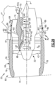
- FIG. 1 schematically illustrates a gas turbine engine 20.
- the gas turbine engine 20 is disclosed herein as a two-spool turbofan that generally incorporates a fan section 22, a compressor section 24, a combustor section 26 and a turbine section 28.
- Alternative engines might include an augmentor section (not shown) among other systems or features.
- the fan section 22 drives air along a bypass flow path B in a bypass duct defined within a nacelle 15, while the compressor section 24 drives air along a core flow path C for compression and communication into the combustor section 26 then expansion through the turbine section 28.
- the exemplary engine 20 generally includes a low speed spool 30 and a high speed spool 32 mounted for rotation about an engine central longitudinal axis A relative to an engine static structure 36 via several bearing systems 38. It should be understood that various bearing systems 38 at various locations may alternatively or additionally be provided, and the location of bearing systems 38 may be varied as appropriate to the application.
- the low speed spool 30 generally includes an inner shaft 40 that interconnects a fan 42, a first (or low) pressure compressor 44 and a first (or low) pressure turbine 46.
- the inner shaft 40 is connected to the fan 42 through a speed change mechanism, which in exemplary gas turbine engine 20 is illustrated as a geared architecture 48 to drive the fan 42 at a lower speed than the low speed spool 30.
- the high speed spool 32 includes an outer shaft 50 that interconnects a second (or high) pressure compressor 52 and a second (or high) pressure turbine 54.
- a combustor 56 is arranged in exemplary gas turbine 20 between the high pressure compressor 52 and the high pressure turbine 54.
- a mid-turbine frame 57 of the engine static structure 36 is arranged generally between the high pressure turbine 54 and the low pressure turbine 46.
- the mid-turbine frame 57 further supports bearing systems 38 in the turbine section 28.
- the inner shaft 40 and the outer shaft 50 are concentric and rotate via bearing systems 38 about the engine central longitudinal axis A which is collinear with their longitudinal axes.
- the core airflow is compressed by the low pressure compressor 44 then the high pressure compressor 52, mixed and burned with fuel in the combustor 56, then expanded over the high pressure turbine 54 and low pressure turbine 46.
- the mid-turbine frame 57 includes airfoils 59 which are in the core airflow path C.
- the turbines 46, 54 rotationally drive the respective low speed spool 30 and high speed spool 32 in response to the expansion.
- gear system 48 may be located aft of combustor section 26 or even aft of turbine section 28, and fan section 22 may be positioned forward or aft of the location of gear system 48.
- the engine 20 in one example is a high-bypass geared aircraft engine.
- the engine 20 bypass ratio is greater than about six, with an example embodiment being greater than about ten
- the geared architecture 48 is an epicyclic gear train, such as a planetary gear system or other gear system, with a gear reduction ratio of greater than about 2.3 and the low pressure turbine 46 has a pressure ratio that is greater than about five.
- the engine 20 bypass ratio is greater than about ten
- the fan diameter is significantly larger than that of the low pressure compressor 44
- the low pressure turbine 46 has a pressure ratio that is greater than about five.
- Low pressure turbine 46 pressure ratio is pressure measured prior to inlet of low pressure turbine 46 as related to the pressure at the outlet of the low pressure turbine 46 prior to an exhaust nozzle.
- the geared architecture 48 may be an epicycle gear train, such as a planetary gear system or other gear system, with a gear reduction ratio of greater than about 2.3:1. It should be understood, however, that the above parameters are only exemplary of one embodiment of a geared architecture engine and that the present invention is applicable to other gas turbine engines including direct drive turbofans.
- the fan section 22 of the engine 20 is designed for a particular flight condition -- typically cruise at about 0.8 Mach and about 35,000 feet (10,668 m).
- the flight condition of 0.8 Mach and 35,000 ft (10,668 m), with the engine at its best fuel consumption - also known as "bucket cruise Thrust Specific Fuel Consumption ('TSFC')" - is the industry standard parameter of lbm of fuel being burned divided by lbf of thrust the engine produces at that minimum point.
- "Low fan pressure ratio” is the pressure ratio across the fan blade alone, without a Fan Exit Guide Vane (“FEGV”) system.
- the low fan pressure ratio as disclosed herein according to one non-limiting embodiment is less than about 1.45.
- the "Low corrected fan tip speed” as disclosed herein according to one non-limiting embodiment is less than about 1150 ft / second (350.5 m/s).
- a nacelle assembly 60 is shown disposed about the engine axis A.
- like reference numerals designate like elements where appropriate and reference numerals with the addition of one-hundred or multiples thereof designate modified elements that are understood to incorporate the same features and benefits of the corresponding original elements.
- the nacelle assembly 60 can be fixedly attached to a pylon P.
- the pylon P is configured to support the nacelle assembly 60 and engine 20 on an aircraft.
- the nacelle assembly 60 includes a core cowling 62, a fan nacelle 64 and a bypass duct 66 defining the bypass flow path B.
- the core cowling 62 extends circumferentially around, and at least partially houses, the engine sections 24, 26, 28 and geared architecture 48.
- the core cowling 62 extends axially along the engine axis A between a core inlet 68 and a core nozzle 70 to define the core flow path C.
- the core nozzle 70 defines an exhaust flow path for combustion products communicated from the turbine section 28.
- the fan nacelle 64 extends circumferentially around and houses the fan 42 and at least a portion of the core cowling 62 to define the bypass flow path B.
- the fan nacelle 64 includes an annular body 64 A that extends axially along the engine axis A between a nacelle inlet 72 and a bypass nozzle 74 of the bypass flow path B.
- a leading edge region 64 B of fan nacelle 64 defines the nacelle inlet 72.
- the leading edge region 64 B extends axially between the nacelle inlet 72 and the fan 42.
- a trailing edge region 64 C of the fan nacelle 64 defines the bypass nozzle 74.
- the fan nacelle 64 can include one or more segments fixed or moveable relative to each other and/or the engine axis A.
- the bypass nozzle 74 can be substantially fixed relative to the nacelle inlet 72 such that an exit area of the bypass flow path B remains substantially constant.
- the nacelle assembly 60 includes a thrust reverser 82 and a variable area nozzle 84 for adjusting various characteristics of the bypass flow path B.
- Figure 2A illustrates the thrust reverser 82 and the variable area nozzle 84 in stowed positions.
- Figure 2B illustrates the thrust reverser 82 in a deployed position and the variable area nozzle 84 in a stowed position.
- Figure 2C illustrates the thrust reverser 82 in the stowed position and the variable area nozzle 84 in a deployed position.
- the nacelle assembly 60 includes only one of the thrust reverser 82 and variable area nozzle 84.
- the fan nacelle 64 includes a stationary first nacelle section 78 and a second nacelle section 80 aft of the first nacelle section 78.
- the second nacelle section 80 is moveable relative to the first nacelle section 78.
- the second nacelle section 80 can translate along a supporting structure such as a plurality of guides or tracks 81 ( Figure 2B ).
- the thrust reverser 82 can include one or more cascades 85 of turning vanes and blocker doors 83 (shown in dashed lines) arranged circumferentially around the engine axis A to direct flow F from the bypass flow path B for providing reverse engine thrust.
- the thrust reverser 82 is configured without blocker doors.
- the second nacelle section 80 is moveable relative to the first nacelle section 78 to deploy and stow the cascades 85.
- the variable area nozzle 84 is defined by a third nacelle section 86 of the fan nacelle 64.
- the third nacelle section 86 is moveable between the stowed position of Figures 2A-2B and the deployed position of Figure 2C utilizing one or more actuators.
- the first nacelle section 78 defines the leading edge region 64 B and the third nacelle section 86 defines the trailing edge region 64 C of the fan nacelle 64.
- the second nacelle section 80 defines the trailing edge region 64 C .
- a radial distance 75 of the bypass nozzle 74 between a trailing edge of the third nacelle section 86 and the core cowling 62 may change (e.g., increase) to radial distance 75' and thereby change (e.g., increase) a flow area of the bypass nozzle 74.
- the variable area nozzle 84 may adjust a pressure ratio across the bypass flow path B by changing the flow area of the bypass nozzle 74.
- the variable area nozzle 84 can define at least one auxiliary port 77 to affect the bypass flow.
- the auxiliary port 77 is defined between an upstream portion of the second nacelle section 80 and the third nacelle section 86 as the third nacelle section 86 translates axially aftwards relative to the upstream portion.
- Communication of flow F A ( Figure 2C ) through auxiliary port 77 increases an effective flow area of the variable area nozzle 84.
- the variable area nozzle 84 therefore may adjust a pressure ratio across the bypass flow path B.
- the variable area nozzle 84 includes one or more bodies (e.g., flaps similar to blocker doors 83) that may move radially and/or axially to change the flow area of the bypass nozzle 74.
- Figures 3A-3B illustrate a deflection measurement assembly 88, according to an example.
- the deflection measurement assembly 88 is operable to determine or sense a change in a cross-sectional area of the bypass or core flow paths B, C due to a change in loads caused by pressure loads exerted on surfaces of the nacelle assembly 60 during engine operation or test conditions.
- the deflection measurement assembly 88 may utilize the sensed change in the cross-sectional area to determine a deflection of the nacelle assembly 60 at a corresponding location of the cross-section.
- the deflection measurement assembly 88 includes a cable assembly 89 and at least one transducer 90 actuated by the cable assembly 89.
- the transducer 90 is a linear variable differential transducer (LVDT).
- the transducer 90 includes an actuator 90 A moveable relative to a body 90 B , and can be spring loaded to return the actuator 90 A to a neutral position or state.
- the transducer 90 is a rotary variable differential transducer (RVDT).
- Other example transducers can include a load cell responsive to force changes caused by movement of the cable assembly 89.
- body 90 B can be a tension load cell
- actuator 90 A can be a linkage rod 90 A coupled to the tension load cell.
- the cable assembly 89 includes at least one cable 92 or cable segments circumferentially arranged at least partially about the engine axis A.
- the cable 92 can be disposed at least partially about a peripheral region 61 of the nacelle assembly 60.
- the peripheral region 61 is defined as a perimeter of the first nacelle section 78 of the nacelle assembly 60.
- the cable 92 is adjacent to an outer diameter of the bypass nozzle 74 to form a partial loop which extends at least 180 degrees about the engine axis A.
- the cable assembly 89 can be situated at other locations of the nacelle assembly 60, such as an inner or outer diameter of core cowling 62 adjacent to the core nozzle 70.
- the cable 92 can be configured to extend less than 180 degrees about the engine axis A to determine deflection of a localized region of the nacelle assembly 60.
- the deflection measurement assembly includes an array of transducers and cable assemblies arranged about the engine axis A to determine deflection at different localized areas of the nacelle assembly 60.
- Figure 8 illustrates deflection measurement assembly 388 having a plurality of transducers 390 arranged about engine axis A, with each transducer 390 coupled to a corresponding cable assembly 289.
- a length of the cable 92 extends through one or more guides 94 positioned at spaced intervals along the nacelle assembly 60.
- Each guide 94 includes a body 94 A attachable to the nacelle assembly 60.
- the body 94 A defines a contoured opening 94 B for routing a portion of the cable 92, as illustrated by Figures 4A and 4B .
- a first end 92 A of the cable 92 is fixedly attached or otherwise coupled to actuator 90 A of the transducer 90, and a second end 92 B of the cable 92 is fixedly attached or otherwise coupled to the pylon P.
- the second end 92 B is fixedly attached to the nacelle assembly 60.
- the deflection measurement assembly 88 includes a mount 96 configured to attach the transducer 90 to the nacelle assembly 60.
- the mount 96 includes a first portion 96 A and a second portion 96 B .
- the first and second portions 96 A , 96 B can define a passage 96 C for receiving a portion of the transducer 90.
- the first portion 96 A can be fixedly attached to the transducer 90, and the second portion 96 B can be fixedly attached to the nacelle assembly 60 at a desired location.
- the first and second portions 96 A , 96 B are fixedly attached by one or more fasteners such that relative movement is minimized.
- the first portion 96 A is moveable relative to the second portion 96 B such that the transducer 90 is moveable relative to the nacelle assembly 60.
- the mount 96 includes a cable interface 97 and one or more springs 98, with the first end 92 A of the cable 92 coupled to the cable interface 97.
- Each spring 98 is coupled to the cable interface 97 and to a post 99 extending from the mount 96.
- the springs 98 bias the cable 92 towards the transducer 90 to provide a desired amount of tension on the cable 92.
- the first end 92 A of the cable 92 is attached to the actuator 90 A via a spring to provide a desired tension, or is directly attached to the actuator 90 A .
- the deflection measurement assembly 88 includes a controller 91 coupled to secondary coils of the transducer 90.
- the controller 91 is configured to measure a linear displacement of actuator 90 A based upon measured induced voltage changes caused by movement of a core of the actuator 90 A relative to primary and secondary coils of the transducer 90.
- the controller 91 is operable to determine a deflection of the nacelle assembly 60 at a desired location L 1 corresponding to the cable assembly 89 based upon the displacement.
- the controller 91 is operable to determine the deflection based on comparing the voltage changes of the transducer 90 to one or more predetermined values.
- the controller 91 typically includes a processor, a memory and an interface.
- the processor may, for example only, be any type of known microprocessor having desired performance characteristics.
- the memory may, for example only, includes UVPROM, EEPROM, FLASH, RAM, ROM, DVD, CD, a hard drive, or other computer readable medium which may store data and an algorithm for operation of the deflection measurement assembly as described herein.
- the interface facilitates communication with the other systems or components of the engine 20 or aircraft.
- the controller 91 can be a portion of a full authority digital engine control (FADEC) such as an electronic engine controller (EEC), another system, or a stand-alone system, for example.
- FADEC full authority digital engine control
- EEC electronic engine controller
- deflection can occur due to pressure loads which cause surfaces of the nacelle assembly 60 to move radially outward.
- the cable assembly 89 is moveable relative to the engine axis A in response to a change in a cross-sectional area of the flow path.
- the transducer 90 is actuated in response to movement of the cable assembly 89 caused by a change in the effective length of the cable assembly 89.
- the controller 91 is operable to determine a change in the cross-sectional area based on comparing the displacement of the actuator 90 A to a predetermined quantity at a corresponding operating condition.
- the corresponding operating condition may be full power of the engine 20 or another operating condition, such as a cruise condition.
- the controller 91 is operable to determine deflection of the nacelle assembly 60 based on the change in the cross-sectional area.
- the controller 91 can be operable to cause a performance characteristic of the engine 20 to change based upon the deflection, such as adjusting a power output of the engine 20 at a desired operating condition.
- the calculated deflection can be utilized for adjusting flow and thrust performance calculations during design, testing or calibration.
- Figure 6 illustrates a deflection measurement assembly 188 according to a second example.
- Cable assembly 189 is situated at least partially within a cavity 163 of the nacelle assembly 160.
- the cavity 163 can be defined by trailing edge region 64 C of the fan nacelle 64 or a trailing edge region 62 C of the core cowling 62 ( Figure 2A ), for example.
- Transducer 190 is coupled to first end 192 A and second end 192 B of cable 192 to form a substantially full loop.
- the mount 196 is configured to permit the transducer 190 to move relative to the nacelle assembly 160.
- FIG 7 illustrates a plan view of a deflection measurement assembly 288 according to a third embodiment.
- Transducer 290 can be a rotary variable differential transducer (RVDT).
- Actuator 290 A extends outward from body 290 B .
- the actuator 290 A can extend radially outwardly with respect to engine axis A ( Figure 2 ).
- the actuator 290 A can extend in the circumferential direction with respect to engine axis A ( Figure 2 ).
- the actuator 290 A is offset from, and pivotably coupled to, cable 292 of cable assembly 289 by one or more linkage arms 295. Movement of cable 292 causes the linkage arms 295 to rotate actuator 290 A .
- Controller 291 is operable to determine a change in the cross-sectional area or also deflection based on comparing a radial displacement of actuator 290 A .
Landscapes
- Engineering & Computer Science (AREA)
- Chemical & Material Sciences (AREA)
- Combustion & Propulsion (AREA)
- Mechanical Engineering (AREA)
- General Engineering & Computer Science (AREA)
- Physics & Mathematics (AREA)
- General Physics & Mathematics (AREA)
- Aviation & Aerospace Engineering (AREA)
- Ocean & Marine Engineering (AREA)
- Structures Of Non-Positive Displacement Pumps (AREA)
- Testing Of Engines (AREA)
Claims (11)
- Ensemble de mesure de déformation (88 ; 188 ; 288 ; 388) pour un moteur à turbine à gaz, comprenant :une nacelle (64) disposée autour d'un axe (A) pour définir un trajet d'écoulement (B), la nacelle (64) comportant une première section de nacelle stationnaire (78) et une seconde section de nacelle (80) à l'arrière de la première section de nacelle stationnaire (78), dans lequel la seconde section de nacelle (80) est mobile par rapport à la première section de nacelle stationnaire (78) ;un ensemble câble (89 ; 189 ; 289 ; 389) disposé circonférentiellement au moins partiellement autour de l'axe (A), l'ensemble câble (89 ; 189 ; 289 ; 389) étant mobile par rapport à l'axe (A) en réponse à un changement de superficie de la section transversale du trajet d'écoulement (B) ;un transducteur (90 ; 190 ; 290 ; 390) couplé à l'ensemble câble (89...389) et configuré pour être actionné par l'ensemble câble (89...389) ; etun dispositif de commande (91 ; 191 ; 291 ; 391) couplé au transducteur (90...390), le dispositif de commande (91...391) pouvant être utilisé pour déterminer une déformation de la nacelle (64) en réponse à l'actionnement du transducteur (90...390) ;caractérisé en ce que :l'ensemble câble (89...389) comporte au moins un câble (92 ; 192 ; 292 ; 392) disposé au moins partiellement autour d'un périmètre de la première section de nacelle stationnaire (78) ; etla déformation concerne le changement d'une zone de section transversale du trajet d'écoulement (B) à un emplacement correspondant à l'ensemble câble (89...389) le long de la première section de nacelle stationnaire (78).
- Ensemble selon la revendication 1, dans lequel le transducteur (90...390) est couplé à une première extrémité (92A ; 192A) de l'au moins un câble (92...392).
- Ensemble selon la revendication 2, dans lequel le transducteur (90...390) est couplé à une seconde extrémité (92B ; 192B) de l'au moins un câble (92...392).
- Ensemble selon une quelconque revendication précédente, comprenant un support (96 ; 196 ; 296 ; 396) comportant une première partie (96A) fixée solidement à la nacelle (64) et une seconde partie (96B) fixée solidement au transducteur (90...390).
- Système de propulsion, comprenant :l'ensemble de mesure de déformation (88...388) selon une quelconque revendication précédente ;un moteur à turbine à gaz (20) définissant l'axe (A), le moteur (20) comportant une section turbine (28) configurée pour entraîner une section soufflante (22) ; etun ensemble nacelle (60 ; 160 ; 360) comportant la nacelle (64) et un capot central (62) disposé autour de l'axe (A) pour définir un trajet d'écoulement de dérivation (B), et le capot central (62) définissant un trajet d'écoulement central (C), dans lequel l'ensemble câble (89...389) est couplé à l'ensemble nacelle (60 ; 160 ; 360), et le transducteur (90...390) est configuré pour être actionné par l'ensemble câble (89...389) en réponse au changement dans une zone de section transversale d'au moins l'un parmi le trajet d'écoulement de dérivation (B) et/ou le trajet d'écoulement central (C).
- Système de propulsion selon la revendication 5, dans lequel la nacelle de soufflante (64) est fixée solidement à un pylône (P), le transducteur (90...390) est couplé à une première extrémité (92A ; 192A) de l'au moins un câble (92...392), et une seconde extrémité (92B ; 192B) dudit au moins un câble (92...392) est couplée au pylône (P).
- Ensemble ou système de propulsion selon une quelconque revendication précédente, dans lequel le transducteur (90...390) est un transducteur différentiel variable linéaire.
- Procédé de mesure de déformation d'un ensemble nacelle (60 ; 160 ; 360) pour un moteur à turbine à gaz, comprenant :la fourniture d'une nacelle (64) définissant un trajet d'écoulement (B) qui s'étend le long d'un axe (A), la nacelle (64) comportant une première section de nacelle stationnaire (78) et une seconde section de nacelle (80) à l'arrière de la première section de nacelle stationnaire (78), dans lequel la seconde section de nacelle (80) est mobile par rapport à la première section de nacelle stationnaire (78) ;le positionnement d'un ensemble câble (89...389) circonférentiellement autour de l'axe (A), l'ensemble câble (89...389) étant mobile par rapport à l'axe (A) en réponse à un changement dans une zone de section transversale du trajet d'écoulement (B), dans lequel l'ensemble câble (89...389) comporte au moins un câble (92 ; 192 ; 292 ; 392) disposé au moins partiellement autour d'un périmètre de la première section de nacelle stationnaire (78) ;l'actionnement d'un transducteur (90...390) en réponse au mouvement de l'ensemble câble (89...389) ; etla détermination d'une déformation de la nacelle (64) à un emplacement le long de la première section de nacelle stationnaire (78) adjacente à l'ensemble câble (89...389) en fonction de l'étape d'actionnement du transducteur (90...390).
- Ensemble selon la revendication 8, dans lequel le transducteur (90...390) est couplé à une première extrémité (92A ; 192A) de l'au moins un câble (92...392).
- Procédé selon la revendication 8 ou 9, dans lequel l'étape de détermination de la déformation de la nacelle (64) comporte la comparaison du changement dans la zone de section transversale à une quantité prédéterminée.
- Ensemble (88...388) selon l'une quelconque des revendications 1 à 4, dans lequel la seconde section de nacelle (80) définit une région de bord de fuite (64C) de la nacelle (64) .
Applications Claiming Priority (1)
| Application Number | Priority Date | Filing Date | Title |
|---|---|---|---|
| US15/095,199 US10295420B2 (en) | 2016-04-11 | 2016-04-11 | Nacelle deflection measurement assembly |
Publications (2)
| Publication Number | Publication Date |
|---|---|
| EP3232017A1 EP3232017A1 (fr) | 2017-10-18 |
| EP3232017B1 true EP3232017B1 (fr) | 2023-12-20 |
Family
ID=58548563
Family Applications (1)
| Application Number | Title | Priority Date | Filing Date |
|---|---|---|---|
| EP17166095.4A Active EP3232017B1 (fr) | 2016-04-11 | 2017-04-11 | Ensemble de mesure de déformation de nacelle |
Country Status (2)
| Country | Link |
|---|---|
| US (1) | US10295420B2 (fr) |
| EP (1) | EP3232017B1 (fr) |
Families Citing this family (4)
| Publication number | Priority date | Publication date | Assignee | Title |
|---|---|---|---|---|
| CN112985812B (zh) * | 2019-12-18 | 2023-01-06 | 中国航发商用航空发动机有限责任公司 | 短舱试验装置和发动机试验系统 |
| US12618369B2 (en) | 2020-10-16 | 2026-05-05 | General Electric Company | Propulsion engine and cowl |
| US11421607B1 (en) | 2021-06-10 | 2022-08-23 | Raytheon Technologies Corporation | Fiber optic exit area sensing for gas turbine engine nozzles |
| FR3158499A1 (fr) * | 2024-01-22 | 2025-07-25 | Safran Aircraft Engines | Ensemble comportant une turbomachine d’aeronef et son pylone d’accrochage |
Family Cites Families (11)
| Publication number | Priority date | Publication date | Assignee | Title |
|---|---|---|---|---|
| US2634578A (en) * | 1949-02-19 | 1953-04-14 | Mcdonnell Aircraft Corp | Device for varying the effective area of discharge orifices of jet engines or afterburners therefor |
| DE1235673B (de) | 1964-07-02 | 1967-03-02 | Pacific Scientific Co | Mechanische Rueckfuehreinrichtung |
| US5385013A (en) | 1993-03-03 | 1995-01-31 | General Electric Company | Aircraft gas turbine engine backbone deflection thermal control |
| US5524847A (en) | 1993-09-07 | 1996-06-11 | United Technologies Corporation | Nacelle and mounting arrangement for an aircraft engine |
| US8235325B2 (en) | 2005-10-04 | 2012-08-07 | United Technologies Corporation | Fan variable area nozzle positional measurement system |
| US7254997B1 (en) | 2006-10-12 | 2007-08-14 | David Hui | Anti-steal tire pressure monitoring apparatus |
| GB0820174D0 (en) | 2008-11-05 | 2008-12-10 | Rolls Royce Plc | A gas turbine engine variable area exhaust nozzle |
| US20110120079A1 (en) | 2009-11-24 | 2011-05-26 | Schwark Jr Fred W | Variable area fan nozzle stiffeners and placement |
| US9316112B2 (en) | 2011-12-21 | 2016-04-19 | Rohr, Inc. | Variable area fan nozzle with drive system health monitoring |
| US9303590B2 (en) * | 2012-05-22 | 2016-04-05 | Spirit Aerosystems, Inc. | Variable area fan nozzle actuation system |
| US9890739B2 (en) * | 2015-03-23 | 2018-02-13 | The Boeing Company | Controlling nozzle areas of variable area fan nozzles |
-
2016
- 2016-04-11 US US15/095,199 patent/US10295420B2/en active Active
-
2017
- 2017-04-11 EP EP17166095.4A patent/EP3232017B1/fr active Active
Also Published As
| Publication number | Publication date |
|---|---|
| EP3232017A1 (fr) | 2017-10-18 |
| US20170292882A1 (en) | 2017-10-12 |
| US10295420B2 (en) | 2019-05-21 |
Similar Documents
| Publication | Publication Date | Title |
|---|---|---|
| US10822989B2 (en) | Adjustable blade outer air seal apparatus | |
| EP3199766B1 (fr) | Agencement de pale de soufflante à pas variable pour moteur à turbine à gaz | |
| EP2971598B1 (fr) | Système de commande d'aubes à incidence variable | |
| EP3232016B1 (fr) | Procédé et appareil de réglage d'aubes variables | |
| US8863491B2 (en) | Gas turbine engine shaft bearing configuration | |
| US10400621B2 (en) | Pivot door thrust reverser with variable area nozzle | |
| EP2957754B1 (fr) | Tuyère à section variable pour moteur à turbine à gaz | |
| US8961115B2 (en) | Clearance control for gas turbine engine seal | |
| EP2998522B1 (fr) | Aube de stator variable de moteur de turbine | |
| EP3232017A1 (fr) | Ensemble de mesure de déformation de nacelle | |
| EP3869024B1 (fr) | Buse de conduit de dérivation de moteur à haut rapport de dérivation comprenant une zone de buse contrôlée | |
| US20100089028A1 (en) | Corrugated core cowl for a gas turbine engine | |
| EP3564495B1 (fr) | Composant d'échappement de moteur à turbine à gaz | |
| EP3052769B1 (fr) | Rotors de compresseur et de turbine à mouvement de translation permettant la régulation du jeu | |
| US10006404B2 (en) | Gas turbine engine thrust reverser system | |
| EP2890878B1 (fr) | Joint d'étanchéité à l'air externe d'aube | |
| EP3611358B1 (fr) | Système d'actionnement de soupape de purge | |
| WO2015053848A2 (fr) | Plate-forme de soufflante pourvue d'une languette de bord d'attaque |
Legal Events
| Date | Code | Title | Description |
|---|---|---|---|
| PUAI | Public reference made under article 153(3) epc to a published international application that has entered the european phase |
Free format text: ORIGINAL CODE: 0009012 |
|
| STAA | Information on the status of an ep patent application or granted ep patent |
Free format text: STATUS: THE APPLICATION HAS BEEN PUBLISHED |
|
| AK | Designated contracting states |
Kind code of ref document: A1 Designated state(s): AL AT BE BG CH CY CZ DE DK EE ES FI FR GB GR HR HU IE IS IT LI LT LU LV MC MK MT NL NO PL PT RO RS SE SI SK SM TR |
|
| AX | Request for extension of the european patent |
Extension state: BA ME |
|
| STAA | Information on the status of an ep patent application or granted ep patent |
Free format text: STATUS: REQUEST FOR EXAMINATION WAS MADE |
|
| 17P | Request for examination filed |
Effective date: 20180417 |
|
| RBV | Designated contracting states (corrected) |
Designated state(s): AL AT BE BG CH CY CZ DE DK EE ES FI FR GB GR HR HU IE IS IT LI LT LU LV MC MK MT NL NO PL PT RO RS SE SI SK SM TR |
|
| RAP1 | Party data changed (applicant data changed or rights of an application transferred) |
Owner name: RAYTHEON TECHNOLOGIES CORPORATION |
|
| STAA | Information on the status of an ep patent application or granted ep patent |
Free format text: STATUS: EXAMINATION IS IN PROGRESS |
|
| 17Q | First examination report despatched |
Effective date: 20210507 |
|
| GRAP | Despatch of communication of intention to grant a patent |
Free format text: ORIGINAL CODE: EPIDOSNIGR1 |
|
| STAA | Information on the status of an ep patent application or granted ep patent |
Free format text: STATUS: GRANT OF PATENT IS INTENDED |
|
| INTG | Intention to grant announced |
Effective date: 20230718 |
|
| RAP3 | Party data changed (applicant data changed or rights of an application transferred) |
Owner name: RTX CORPORATION |
|
| GRAS | Grant fee paid |
Free format text: ORIGINAL CODE: EPIDOSNIGR3 |
|
| GRAA | (expected) grant |
Free format text: ORIGINAL CODE: 0009210 |
|
| STAA | Information on the status of an ep patent application or granted ep patent |
Free format text: STATUS: THE PATENT HAS BEEN GRANTED |
|
| AK | Designated contracting states |
Kind code of ref document: B1 Designated state(s): AL AT BE BG CH CY CZ DE DK EE ES FI FR GB GR HR HU IE IS IT LI LT LU LV MC MK MT NL NO PL PT RO RS SE SI SK SM TR |
|
| REG | Reference to a national code |
Ref country code: GB Ref legal event code: FG4D |
|
| REG | Reference to a national code |
Ref country code: CH Ref legal event code: EP |
|
| REG | Reference to a national code |
Ref country code: DE Ref legal event code: R096 Ref document number: 602017077638 Country of ref document: DE |
|
| REG | Reference to a national code |
Ref country code: IE Ref legal event code: FG4D |
|
| PG25 | Lapsed in a contracting state [announced via postgrant information from national office to epo] |
Ref country code: GR Free format text: LAPSE BECAUSE OF FAILURE TO SUBMIT A TRANSLATION OF THE DESCRIPTION OR TO PAY THE FEE WITHIN THE PRESCRIBED TIME-LIMIT Effective date: 20240321 |
|
| REG | Reference to a national code |
Ref country code: LT Ref legal event code: MG9D |
|
| PG25 | Lapsed in a contracting state [announced via postgrant information from national office to epo] |
Ref country code: LT Free format text: LAPSE BECAUSE OF FAILURE TO SUBMIT A TRANSLATION OF THE DESCRIPTION OR TO PAY THE FEE WITHIN THE PRESCRIBED TIME-LIMIT Effective date: 20231220 |
|
| REG | Reference to a national code |
Ref country code: NL Ref legal event code: MP Effective date: 20231220 |
|
| PG25 | Lapsed in a contracting state [announced via postgrant information from national office to epo] |
Ref country code: ES Free format text: LAPSE BECAUSE OF FAILURE TO SUBMIT A TRANSLATION OF THE DESCRIPTION OR TO PAY THE FEE WITHIN THE PRESCRIBED TIME-LIMIT Effective date: 20231220 |
|
| PG25 | Lapsed in a contracting state [announced via postgrant information from national office to epo] |
Ref country code: LT Free format text: LAPSE BECAUSE OF FAILURE TO SUBMIT A TRANSLATION OF THE DESCRIPTION OR TO PAY THE FEE WITHIN THE PRESCRIBED TIME-LIMIT Effective date: 20231220 Ref country code: GR Free format text: LAPSE BECAUSE OF FAILURE TO SUBMIT A TRANSLATION OF THE DESCRIPTION OR TO PAY THE FEE WITHIN THE PRESCRIBED TIME-LIMIT Effective date: 20240321 Ref country code: FI Free format text: LAPSE BECAUSE OF FAILURE TO SUBMIT A TRANSLATION OF THE DESCRIPTION OR TO PAY THE FEE WITHIN THE PRESCRIBED TIME-LIMIT Effective date: 20231220 Ref country code: ES Free format text: LAPSE BECAUSE OF FAILURE TO SUBMIT A TRANSLATION OF THE DESCRIPTION OR TO PAY THE FEE WITHIN THE PRESCRIBED TIME-LIMIT Effective date: 20231220 Ref country code: BG Free format text: LAPSE BECAUSE OF FAILURE TO SUBMIT A TRANSLATION OF THE DESCRIPTION OR TO PAY THE FEE WITHIN THE PRESCRIBED TIME-LIMIT Effective date: 20240320 |
|
| REG | Reference to a national code |
Ref country code: AT Ref legal event code: MK05 Ref document number: 1642620 Country of ref document: AT Kind code of ref document: T Effective date: 20231220 |
|
| PG25 | Lapsed in a contracting state [announced via postgrant information from national office to epo] |
Ref country code: NL Free format text: LAPSE BECAUSE OF FAILURE TO SUBMIT A TRANSLATION OF THE DESCRIPTION OR TO PAY THE FEE WITHIN THE PRESCRIBED TIME-LIMIT Effective date: 20231220 |
|
| PG25 | Lapsed in a contracting state [announced via postgrant information from national office to epo] |
Ref country code: SE Free format text: LAPSE BECAUSE OF FAILURE TO SUBMIT A TRANSLATION OF THE DESCRIPTION OR TO PAY THE FEE WITHIN THE PRESCRIBED TIME-LIMIT Effective date: 20231220 Ref country code: RS Free format text: LAPSE BECAUSE OF FAILURE TO SUBMIT A TRANSLATION OF THE DESCRIPTION OR TO PAY THE FEE WITHIN THE PRESCRIBED TIME-LIMIT Effective date: 20231220 Ref country code: NO Free format text: LAPSE BECAUSE OF FAILURE TO SUBMIT A TRANSLATION OF THE DESCRIPTION OR TO PAY THE FEE WITHIN THE PRESCRIBED TIME-LIMIT Effective date: 20240320 Ref country code: NL Free format text: LAPSE BECAUSE OF FAILURE TO SUBMIT A TRANSLATION OF THE DESCRIPTION OR TO PAY THE FEE WITHIN THE PRESCRIBED TIME-LIMIT Effective date: 20231220 Ref country code: LV Free format text: LAPSE BECAUSE OF FAILURE TO SUBMIT A TRANSLATION OF THE DESCRIPTION OR TO PAY THE FEE WITHIN THE PRESCRIBED TIME-LIMIT Effective date: 20231220 Ref country code: HR Free format text: LAPSE BECAUSE OF FAILURE TO SUBMIT A TRANSLATION OF THE DESCRIPTION OR TO PAY THE FEE WITHIN THE PRESCRIBED TIME-LIMIT Effective date: 20231220 |
|
| PG25 | Lapsed in a contracting state [announced via postgrant information from national office to epo] |
Ref country code: IS Free format text: LAPSE BECAUSE OF FAILURE TO SUBMIT A TRANSLATION OF THE DESCRIPTION OR TO PAY THE FEE WITHIN THE PRESCRIBED TIME-LIMIT Effective date: 20240420 |
|
| PG25 | Lapsed in a contracting state [announced via postgrant information from national office to epo] |
Ref country code: CZ Free format text: LAPSE BECAUSE OF FAILURE TO SUBMIT A TRANSLATION OF THE DESCRIPTION OR TO PAY THE FEE WITHIN THE PRESCRIBED TIME-LIMIT Effective date: 20231220 Ref country code: AT Free format text: LAPSE BECAUSE OF FAILURE TO SUBMIT A TRANSLATION OF THE DESCRIPTION OR TO PAY THE FEE WITHIN THE PRESCRIBED TIME-LIMIT Effective date: 20231220 |
|
| PG25 | Lapsed in a contracting state [announced via postgrant information from national office to epo] |
Ref country code: SK Free format text: LAPSE BECAUSE OF FAILURE TO SUBMIT A TRANSLATION OF THE DESCRIPTION OR TO PAY THE FEE WITHIN THE PRESCRIBED TIME-LIMIT Effective date: 20231220 |
|
| PG25 | Lapsed in a contracting state [announced via postgrant information from national office to epo] |
Ref country code: SM Free format text: LAPSE BECAUSE OF FAILURE TO SUBMIT A TRANSLATION OF THE DESCRIPTION OR TO PAY THE FEE WITHIN THE PRESCRIBED TIME-LIMIT Effective date: 20231220 Ref country code: SK Free format text: LAPSE BECAUSE OF FAILURE TO SUBMIT A TRANSLATION OF THE DESCRIPTION OR TO PAY THE FEE WITHIN THE PRESCRIBED TIME-LIMIT Effective date: 20231220 Ref country code: RO Free format text: LAPSE BECAUSE OF FAILURE TO SUBMIT A TRANSLATION OF THE DESCRIPTION OR TO PAY THE FEE WITHIN THE PRESCRIBED TIME-LIMIT Effective date: 20231220 Ref country code: IT Free format text: LAPSE BECAUSE OF FAILURE TO SUBMIT A TRANSLATION OF THE DESCRIPTION OR TO PAY THE FEE WITHIN THE PRESCRIBED TIME-LIMIT Effective date: 20231220 Ref country code: IS Free format text: LAPSE BECAUSE OF FAILURE TO SUBMIT A TRANSLATION OF THE DESCRIPTION OR TO PAY THE FEE WITHIN THE PRESCRIBED TIME-LIMIT Effective date: 20240420 Ref country code: EE Free format text: LAPSE BECAUSE OF FAILURE TO SUBMIT A TRANSLATION OF THE DESCRIPTION OR TO PAY THE FEE WITHIN THE PRESCRIBED TIME-LIMIT Effective date: 20231220 Ref country code: CZ Free format text: LAPSE BECAUSE OF FAILURE TO SUBMIT A TRANSLATION OF THE DESCRIPTION OR TO PAY THE FEE WITHIN THE PRESCRIBED TIME-LIMIT Effective date: 20231220 Ref country code: AT Free format text: LAPSE BECAUSE OF FAILURE TO SUBMIT A TRANSLATION OF THE DESCRIPTION OR TO PAY THE FEE WITHIN THE PRESCRIBED TIME-LIMIT Effective date: 20231220 |
|
| PG25 | Lapsed in a contracting state [announced via postgrant information from national office to epo] |
Ref country code: PT Free format text: LAPSE BECAUSE OF FAILURE TO SUBMIT A TRANSLATION OF THE DESCRIPTION OR TO PAY THE FEE WITHIN THE PRESCRIBED TIME-LIMIT Effective date: 20240422 Ref country code: PL Free format text: LAPSE BECAUSE OF FAILURE TO SUBMIT A TRANSLATION OF THE DESCRIPTION OR TO PAY THE FEE WITHIN THE PRESCRIBED TIME-LIMIT Effective date: 20231220 |
|
| PG25 | Lapsed in a contracting state [announced via postgrant information from national office to epo] |
Ref country code: PT Free format text: LAPSE BECAUSE OF FAILURE TO SUBMIT A TRANSLATION OF THE DESCRIPTION OR TO PAY THE FEE WITHIN THE PRESCRIBED TIME-LIMIT Effective date: 20240422 Ref country code: PL Free format text: LAPSE BECAUSE OF FAILURE TO SUBMIT A TRANSLATION OF THE DESCRIPTION OR TO PAY THE FEE WITHIN THE PRESCRIBED TIME-LIMIT Effective date: 20231220 |
|
| REG | Reference to a national code |
Ref country code: DE Ref legal event code: R097 Ref document number: 602017077638 Country of ref document: DE |
|
| PG25 | Lapsed in a contracting state [announced via postgrant information from national office to epo] |
Ref country code: DK Free format text: LAPSE BECAUSE OF FAILURE TO SUBMIT A TRANSLATION OF THE DESCRIPTION OR TO PAY THE FEE WITHIN THE PRESCRIBED TIME-LIMIT Effective date: 20231220 |
|
| PLBE | No opposition filed within time limit |
Free format text: ORIGINAL CODE: 0009261 |
|
| STAA | Information on the status of an ep patent application or granted ep patent |
Free format text: STATUS: NO OPPOSITION FILED WITHIN TIME LIMIT |
|
| PG25 | Lapsed in a contracting state [announced via postgrant information from national office to epo] |
Ref country code: SI Free format text: LAPSE BECAUSE OF FAILURE TO SUBMIT A TRANSLATION OF THE DESCRIPTION OR TO PAY THE FEE WITHIN THE PRESCRIBED TIME-LIMIT Effective date: 20231220 |
|
| PG25 | Lapsed in a contracting state [announced via postgrant information from national office to epo] |
Ref country code: SI Free format text: LAPSE BECAUSE OF FAILURE TO SUBMIT A TRANSLATION OF THE DESCRIPTION OR TO PAY THE FEE WITHIN THE PRESCRIBED TIME-LIMIT Effective date: 20231220 Ref country code: DK Free format text: LAPSE BECAUSE OF FAILURE TO SUBMIT A TRANSLATION OF THE DESCRIPTION OR TO PAY THE FEE WITHIN THE PRESCRIBED TIME-LIMIT Effective date: 20231220 |
|
| PG25 | Lapsed in a contracting state [announced via postgrant information from national office to epo] |
Ref country code: MC Free format text: LAPSE BECAUSE OF FAILURE TO SUBMIT A TRANSLATION OF THE DESCRIPTION OR TO PAY THE FEE WITHIN THE PRESCRIBED TIME-LIMIT Effective date: 20231220 |
|
| 26N | No opposition filed |
Effective date: 20240923 |
|
| PG25 | Lapsed in a contracting state [announced via postgrant information from national office to epo] |
Ref country code: MC Free format text: LAPSE BECAUSE OF FAILURE TO SUBMIT A TRANSLATION OF THE DESCRIPTION OR TO PAY THE FEE WITHIN THE PRESCRIBED TIME-LIMIT Effective date: 20231220 |
|
| REG | Reference to a national code |
Ref country code: CH Ref legal event code: PL |
|
| PG25 | Lapsed in a contracting state [announced via postgrant information from national office to epo] |
Ref country code: LU Free format text: LAPSE BECAUSE OF NON-PAYMENT OF DUE FEES Effective date: 20240411 |
|
| REG | Reference to a national code |
Ref country code: BE Ref legal event code: MM Effective date: 20240430 |
|
| PG25 | Lapsed in a contracting state [announced via postgrant information from national office to epo] |
Ref country code: LU Free format text: LAPSE BECAUSE OF NON-PAYMENT OF DUE FEES Effective date: 20240411 |
|
| PG25 | Lapsed in a contracting state [announced via postgrant information from national office to epo] |
Ref country code: BE Free format text: LAPSE BECAUSE OF NON-PAYMENT OF DUE FEES Effective date: 20240430 |
|
| PG25 | Lapsed in a contracting state [announced via postgrant information from national office to epo] |
Ref country code: BE Free format text: LAPSE BECAUSE OF NON-PAYMENT OF DUE FEES Effective date: 20240430 Ref country code: CH Free format text: LAPSE BECAUSE OF NON-PAYMENT OF DUE FEES Effective date: 20240430 |
|
| PG25 | Lapsed in a contracting state [announced via postgrant information from national office to epo] |
Ref country code: IE Free format text: LAPSE BECAUSE OF NON-PAYMENT OF DUE FEES Effective date: 20240411 |
|
| PGFP | Annual fee paid to national office [announced via postgrant information from national office to epo] |
Ref country code: DE Payment date: 20250319 Year of fee payment: 9 |
|
| PG25 | Lapsed in a contracting state [announced via postgrant information from national office to epo] |
Ref country code: CY Free format text: LAPSE BECAUSE OF FAILURE TO SUBMIT A TRANSLATION OF THE DESCRIPTION OR TO PAY THE FEE WITHIN THE PRESCRIBED TIME-LIMIT; INVALID AB INITIO Effective date: 20170411 |
|
| PG25 | Lapsed in a contracting state [announced via postgrant information from national office to epo] |
Ref country code: HU Free format text: LAPSE BECAUSE OF FAILURE TO SUBMIT A TRANSLATION OF THE DESCRIPTION OR TO PAY THE FEE WITHIN THE PRESCRIBED TIME-LIMIT; INVALID AB INITIO Effective date: 20170411 |
|
| P01 | Opt-out of the competence of the unified patent court (upc) registered |
Free format text: CASE NUMBER: UPC_APP_0017126_3232017/2025 Effective date: 20251211 |
|
| PGFP | Annual fee paid to national office [announced via postgrant information from national office to epo] |
Ref country code: GB Payment date: 20260319 Year of fee payment: 10 |
|
| PGFP | Annual fee paid to national office [announced via postgrant information from national office to epo] |
Ref country code: FR Payment date: 20260319 Year of fee payment: 10 |