EP3232028B1 - Optimierte anordnung eines auspuffsammelrohrs mit schwalbenschwanzbefestigung - Google Patents
Optimierte anordnung eines auspuffsammelrohrs mit schwalbenschwanzbefestigung Download PDFInfo
- Publication number
- EP3232028B1 EP3232028B1 EP17158614.2A EP17158614A EP3232028B1 EP 3232028 B1 EP3232028 B1 EP 3232028B1 EP 17158614 A EP17158614 A EP 17158614A EP 3232028 B1 EP3232028 B1 EP 3232028B1
- Authority
- EP
- European Patent Office
- Prior art keywords
- wall
- cylinder head
- attachment
- bearing
- arrangement according
- Prior art date
- Legal status (The legal status is an assumption and is not a legal conclusion. Google has not performed a legal analysis and makes no representation as to the accuracy of the status listed.)
- Active
Links
Images


Classifications
-
- F—MECHANICAL ENGINEERING; LIGHTING; HEATING; WEAPONS; BLASTING
- F01—MACHINES OR ENGINES IN GENERAL; ENGINE PLANTS IN GENERAL; STEAM ENGINES
- F01N—GAS-FLOW SILENCERS OR EXHAUST APPARATUS FOR MACHINES OR ENGINES IN GENERAL; GAS-FLOW SILENCERS OR EXHAUST APPARATUS FOR INTERNAL-COMBUSTION ENGINES
- F01N13/00—Exhaust or silencing apparatus characterised by constructional features
- F01N13/08—Other arrangements or adaptations of exhaust conduits
- F01N13/10—Other arrangements or adaptations of exhaust conduits of exhaust manifolds
-
- F—MECHANICAL ENGINEERING; LIGHTING; HEATING; WEAPONS; BLASTING
- F01—MACHINES OR ENGINES IN GENERAL; ENGINE PLANTS IN GENERAL; STEAM ENGINES
- F01N—GAS-FLOW SILENCERS OR EXHAUST APPARATUS FOR MACHINES OR ENGINES IN GENERAL; GAS-FLOW SILENCERS OR EXHAUST APPARATUS FOR INTERNAL-COMBUSTION ENGINES
- F01N13/00—Exhaust or silencing apparatus characterised by constructional features
- F01N13/18—Construction facilitating manufacture, assembly, or disassembly
- F01N13/1805—Fixing exhaust manifolds, exhaust pipes or pipe sections to each other, to engine or to vehicle body
-
- F—MECHANICAL ENGINEERING; LIGHTING; HEATING; WEAPONS; BLASTING
- F01—MACHINES OR ENGINES IN GENERAL; ENGINE PLANTS IN GENERAL; STEAM ENGINES
- F01N—GAS-FLOW SILENCERS OR EXHAUST APPARATUS FOR MACHINES OR ENGINES IN GENERAL; GAS-FLOW SILENCERS OR EXHAUST APPARATUS FOR INTERNAL-COMBUSTION ENGINES
- F01N13/00—Exhaust or silencing apparatus characterised by constructional features
- F01N13/18—Construction facilitating manufacture, assembly, or disassembly
- F01N13/1805—Fixing exhaust manifolds, exhaust pipes or pipe sections to each other, to engine or to vehicle body
- F01N13/1811—Fixing exhaust manifolds, exhaust pipes or pipe sections to each other, to engine or to vehicle body with means permitting relative movement, e.g. compensation of thermal expansion or vibration
-
- F—MECHANICAL ENGINEERING; LIGHTING; HEATING; WEAPONS; BLASTING
- F01—MACHINES OR ENGINES IN GENERAL; ENGINE PLANTS IN GENERAL; STEAM ENGINES
- F01N—GAS-FLOW SILENCERS OR EXHAUST APPARATUS FOR MACHINES OR ENGINES IN GENERAL; GAS-FLOW SILENCERS OR EXHAUST APPARATUS FOR INTERNAL-COMBUSTION ENGINES
- F01N13/00—Exhaust or silencing apparatus characterised by constructional features
- F01N13/18—Construction facilitating manufacture, assembly, or disassembly
- F01N13/1833—Construction facilitating manufacture, assembly, or disassembly specially adapted for small internal combustion engines, e.g. used in model applications
-
- F—MECHANICAL ENGINEERING; LIGHTING; HEATING; WEAPONS; BLASTING
- F01—MACHINES OR ENGINES IN GENERAL; ENGINE PLANTS IN GENERAL; STEAM ENGINES
- F01N—GAS-FLOW SILENCERS OR EXHAUST APPARATUS FOR MACHINES OR ENGINES IN GENERAL; GAS-FLOW SILENCERS OR EXHAUST APPARATUS FOR INTERNAL-COMBUSTION ENGINES
- F01N13/00—Exhaust or silencing apparatus characterised by constructional features
- F01N13/18—Construction facilitating manufacture, assembly, or disassembly
- F01N13/1838—Construction facilitating manufacture, assembly, or disassembly characterised by the type of connection between parts of exhaust or silencing apparatus, e.g. between housing and tubes, between tubes and baffles
- F01N13/1844—Mechanical joints
- F01N13/1855—Mechanical joints the connection being realised by using bolts, screws, rivets or the like
-
- F—MECHANICAL ENGINEERING; LIGHTING; HEATING; WEAPONS; BLASTING
- F01—MACHINES OR ENGINES IN GENERAL; ENGINE PLANTS IN GENERAL; STEAM ENGINES
- F01N—GAS-FLOW SILENCERS OR EXHAUST APPARATUS FOR MACHINES OR ENGINES IN GENERAL; GAS-FLOW SILENCERS OR EXHAUST APPARATUS FOR INTERNAL-COMBUSTION ENGINES
- F01N2260/00—Exhaust treating devices having provisions not otherwise provided for
- F01N2260/10—Exhaust treating devices having provisions not otherwise provided for for avoiding stress caused by expansions or contractions due to temperature variations
-
- F—MECHANICAL ENGINEERING; LIGHTING; HEATING; WEAPONS; BLASTING
- F01—MACHINES OR ENGINES IN GENERAL; ENGINE PLANTS IN GENERAL; STEAM ENGINES
- F01N—GAS-FLOW SILENCERS OR EXHAUST APPARATUS FOR MACHINES OR ENGINES IN GENERAL; GAS-FLOW SILENCERS OR EXHAUST APPARATUS FOR INTERNAL-COMBUSTION ENGINES
- F01N2260/00—Exhaust treating devices having provisions not otherwise provided for
- F01N2260/18—Exhaust treating devices having provisions not otherwise provided for for improving rigidity, e.g. by wings, ribs
-
- F—MECHANICAL ENGINEERING; LIGHTING; HEATING; WEAPONS; BLASTING
- F01—MACHINES OR ENGINES IN GENERAL; ENGINE PLANTS IN GENERAL; STEAM ENGINES
- F01N—GAS-FLOW SILENCERS OR EXHAUST APPARATUS FOR MACHINES OR ENGINES IN GENERAL; GAS-FLOW SILENCERS OR EXHAUST APPARATUS FOR INTERNAL-COMBUSTION ENGINES
- F01N2450/00—Methods or apparatus for fitting, inserting or repairing different elements
- F01N2450/24—Methods or apparatus for fitting, inserting or repairing different elements by bolts, screws, rivets or the like
Definitions
- the present invention relates to a motor vehicle engine exhaust gas collection system.
- the present invention relates more particularly to a system for fixing an exhaust manifold against a wall of a cylinder head and crankcase.
- the present invention relates to a motor vehicle engine.
- the motor engines of motor vehicles comprise an exhaust manifold connected in known manner to a cylinder head at the top of said engine.
- the purpose of the exhaust manifold is to recover exhaust gases resulting from the combustion of air and fuel mixture in cylinders upstream in the direction of circulation of the gases.
- the manifold is generally fixed by flanges and bolts against the wall of the cylinder head in a very rigid manner.
- the different parts of the cylinder head and collector undergo variable heating causing significant temperature differences. Sealing problems therefore appear between the various parts in contact due to distortions, consequences of this rigid attachment and the resulting expansion stresses.
- the engines have a smaller footprint due to a reduced engine compartment space and constraints of architecture and aesthetics of the vehicle, the exhaust manifold is arranged in locations smaller and smaller which does not facilitate the attachment of the collector against the wall of the cylinder head, especially during temperature rises of said collector.
- the publication US5918912 thus discloses a means for attaching an exhaust manifold against a wall of the engine cylinder head.
- Said cylinder wall has connecting surfaces and the manifold comprises at a connecting end upper flanges and lower flanges.
- Said lower flanges are clamped in the connecting surfaces and the upper flanges are held against the wall of said cylinder head by clamping straps.
- Such a combination of the cylinder head and the collector can cause problems at high temperatures, especially for an aluminum cylinder head and a steel or cast iron collector because of the very large differences in thermal expansion between the two materials. A game can be created and the seal between the collector and the cylinder head is no longer assured. In addition, the surfaces of bolt connection require additional machining, which generates an additional manufacturing step and cost.
- the publication FR-A1-2897101 discloses a system for attaching an exhaust manifold against a cylinder wall of a heat engine.
- the manifold includes at a connection end with the yoke a fastener having beveled connection surfaces.
- the fixing system consists of two bars resting on the bevel connection surfaces and fixed against the cylinder wall.
- a disadvantage is that the differential expansion of the cylinder head and the collector can cause an uplift of the upper bar then causing a leak of the system.
- the upper bar is that the bar does not have deformation zones to accompany the differential expansions between the collector and the cylinder head.
- the publication US-A1-2005 / 0268602 discloses a device for fixing an exhaust gas manifold against an engine cylinder head, said manifold having a fixed lower flange secured to the cylinder head and a diametrically opposed upper flange and clamped between the cylinder head and a fixing bar; the upper flange or the fixing bar having an elastic portion.
- a disadvantage is the existence of clearance between the fixing bar and the upper flange which can cause a sealing defect.
- the object of the invention is to remedy these problems and one of the objects of the invention is a device for fixing an exhaust gas manifold against an engine cylinder head wall and crankcase, allowing congestion reduced engine.
- the invention relates more particularly to an exhaust manifold arrangement of an internal combustion engine according to claim 1.
- the manifold arrangement comprises a cylinder head fixed above a crankcase, in addition said collector comprises an upstream end neck in the extension of a gas outlet of the cylinder head, and surrounded by a fixing device having a lower fixing end having a first wall fixed in abutment against a wall of the cylinder head and a second wall bearing against the crankcase.
- the exhaust manifold has a lower end fixed against a support wall of the cylinder head and in abutment against the crankcase, which reduces the bulk of the attachment of the manifold and therefore the engine.
- the fixing device is connected to several gas outlets of the cylinder head, which optimally arranges the exhaust manifolds and reduce the size of the engine.
- the term horizontal orientation refers to a horizontal plane of the joint plane of the cylinder head vis-à-vis the horizontal joint plane of the crankcase and the vertical term is along an axis orthogonal to said joint planes with a downward direction from the crankcase upwards to the cylinder head.
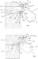
- an exhaust manifold 11 is attached to a wall 12 of a cylinder head 14 of a motor vehicle engine (not shown) for collecting exhaust gases from combustion in the engine cylinders.
- the collector is thus connected at least to an exhaust gas outlet 13.
- exhaust gas manifold is connected to a single gas outlet to facilitate understanding but it goes without saying that said manifold may comprise for example several branches each connected to an exhaust gas outlet of the cylinder head according to the embodiment described below.
- exhaust manifold means a processing element of the exhaust line of the engine.
- said manifold is a catalytic converter attached to a gas outlet of the cylinder head.
- the exhaust gas is then directed for example to a turbine of a turbocharger (not shown).
- the yoke 14 has a horizontal joint plane 16 facing a joint plane 17 of the crankcase 15. Between said two planes is arranged in a known manner a cylinder head gasket 41.
- the crankcase comprises at least one fastening bracket 18, which extends laterally from the side edge 19 of the crankcase.
- Said bracket thus comprises a receiving wall 20 in the extension of the joint plane 17 of the crankcase, carried by a retaining rib 21 extending against a vertical wall of the crankcase along an axis perpendicular to said wall of the crankcase. home 20.
- the crankcase has a sidewalk 40 thus having a receiving wall 20, extending laterally from the joint plane 17 of the crankcase.
- Said sidewalk may also be carried by at least one retaining rib extending against the wall of the cylinder block along an axis substantially orthogonal to the joint plane.
- the collector 11 is fixed to a wall 12 of yoke 14 on a substantially oblique flat surface 22 with respect to the vertical axis.
- Said wall 22 thus extends obliquely from the joint plane 16 of the cylinder head towards the outside of the engine as shown in FIG. figure 2 .
- Said wall 22 forms with the joint plane 16 of the cylinder head an angle of inclination ⁇ between 30 and 80 °, said angle of inclination being defined in the counterclockwise direction from the extension of the joint plane 16 of the cylinder head or from the housing wall 20 of the cylinder block, towards the oblique wall 22 of the cylinder head.
- said angle of inclination is 45 °.
- the manifold 11 comprises an upstream end neck 23 in the direction of flow of the exhaust gas surrounded by a fixing device 10.
- Said device is for example a fastening flange 24 having a passage opening in which is recessed the end collar of the collector.
- the fastening device 10 has a lower end 25 and an opposite upper end 26, each of said two ends has a bevel profile.
- the lower end 25 of said device thus comprises a first support wall 27 pressed against the oblique wall 22 of the cylinder head and a second wall 28 bearing on the cylinder block and more specifically on the housing wall 20 of the housing. cylinders.
- the angle of separation between the two walls 27, 28 of the lower end 25 is therefore acute substantially equal to the angle of inclination ⁇ of the oblique wall 22 of the cylinder head.
- the upper end 26 of the fastening device comprises the bearing wall 27 pressed against the oblique wall 22 of the yoke and a second wall 29 for receiving a head of a fastening element 30 in abutment.
- Said fastening element 30 may be a fastening stud which is pressed into a hole in the wall of the cylinder head through an orifice in the upper end 26 of the fastener 10. The head of the fastener thus presses on the second wall 29 of the upper end.
- the first and second walls 27, 29 of the upper end 26 form between them a spacing angle ⁇ substantially complementary to the spacing angle ⁇ between the two walls 27, 28 of the lower end 25.
- two identical fixing elements are arranged in the upper end and preferably symmetrically with respect to a median vertical plane BB of the device passing through the center of the opening 32 for the passage of the exhaust gases.
- a manifold gasket 33 also surrounding the passage opening 32 of the gas.
- said manifold gasket 33 is substantially plate-shaped and has at the bottom part at least one sheet 34 extending along the lateral side of the cylinder block, said sheet being adapted to preferentially cover the surface of the wall of the cylinder; home 20 of the crankcase. Said sheet 34 may also cover the second wall 28 of the lower end 25 of the fixing device.
- the cylinder head gasket 41 is extended laterally to cover the surface of the housing wall 20 of the crankcase 15.
- the collector gasket 33 stops in part. low at the lower end 42 of the yoke 14.
- the fixing device 10 is secured to the collector 11 by welding between the neck of the collector and the edges of the passage opening of the fastener.
- the fixing device 10 is part of the collector.
- the passage of gases at a very high temperature causes a very significant heating of the collar of the collector 11 and the fixing device.
- the heat is therefore spread substantially radially with respect to the axis X of gas flow.
- the lower end 25 of the fixing device is locked against the oblique wall 22 of the cylinder head and the accommodating wall 28 of the crankcase.
- the upper end 26 is then likely to deform in a substantially radial temperature gradient relative to the axis X of gas flow. Said upper end 26 is then likely to extend radially and the forces generated by said expansion are then transmitted mainly by the beveled support face.
- the upper end 26 is then likely to push substantially on the fastening elements 30 which are the studs which will deform elastically stretching.
- the radial deformation of the upper end can be controlled and directed between the two fastening elements 30.
- the spacing angle ⁇ remains constant and the fastening device 10 is held in abutment against the oblique wall 22 of the yoke.
- the fixing element 30 When the engine is stopped, cold, the fixing element 30 returns to its original shape and presses the bearing face 29 of the upper end 26 to press against the oblique wall 22 of the cylinder head.
- the collector fixing device When cold or hot during the passage of the exhaust gas, the fixing device keeps the exhaust manifold bearing against the wall of the cylinder head to avoid sealing defects.
- Said fixing device comprises a lower end pressed against the cylinder head and resting against the crankcase for offer a small footprint of the engine. The upper end of said fixing device is able to absorb the effects of the transverse expansion of the end flange of the collector.
- the invention is not limited to the embodiments of this plug, described above as examples, it encompasses all variants.
- the upper end can be gripped between a fixing bar and the wall of the cylinder head.
Landscapes
- Engineering & Computer Science (AREA)
- Chemical & Material Sciences (AREA)
- Combustion & Propulsion (AREA)
- Mechanical Engineering (AREA)
- General Engineering & Computer Science (AREA)
- Exhaust Silencers (AREA)
- Cylinder Crankcases Of Internal Combustion Engines (AREA)
Claims (11)
- Abgaskrümmeranordnung (11) eines Verbrennungsmotors, umfassend einen Zylinderkopf (14), der über einem Zylindergehäuse (15) befestigt ist, wobei der Krümmer (11) ein stromaufwärtiges Endrohr (23) umfasst, das mit einem Gasauslass (32) des Zylinderkopfes verbunden ist und von einer Befestigungsvorrichtung (10) umgeben ist, dadurch gekennzeichnet, dass die Befestigungsvorrichtung ein unteres Befestigungsende (25) umfasst, das ein abgeschrägtes Profil aufweist mit einer ersten Wand, die gegen eine Anlagewand (22) des Zylinderkopfes gedrückt ist, die sich schräg nach außerhalb des Zylinderkopfes von einer Fügeebene des Zylinderkopfes (16) aus gegenüber dem Zylindergehäuse erstreckt, und einer zweiten Wand (28), die an einer Aufnahmewand (20) in der Verlängerung einer Fügeebene (17) des Zylindergehäuses gegenüber dem Zylinderkopf anliegt, wobei die erste und zweite Wand (27, 28) des unteren Endes (25) der Befestigungsvorrichtung einen spitzen Öffnungswinkel (β) bilden.
- Anordnung nach Anspruch 1, dadurch gekennzeichnet, dass die Befestigungsvorrichtung (10) ein oberes Ende (26) zur oberen Befestigung umfasst, das an die Anlagewand (22) des Zylinderkopfes gedrückt ist.
- Anordnung nach Anspruch 2, dadurch gekennzeichnet, dass das obere Befestigungsende (26) ein abgeschrägtes Profil aufweist und die erste Wand (27) umfasst, die an der Anlagewand (22) des Zylinderkopfes anliegend befestigt ist, und eine zweite Wand (29), um einen Kopf eines anliegenden Befestigungselements (30) aufzunehmen.
- Anordnung nach Anspruch 3, dadurch gekennzeichnet, dass das obere Befestigungsende (26) mindestens eine Befestigungsöffnung umfasst, die von einem anliegenden Befestigungselement (30) durchquert wird.
- Anordnung nach Anspruch 3 oder 4, dadurch gekennzeichnet, dass das obere Ende (26) der Befestigungsvorrichtung (10) von zwei Befestigungselementen (30) durchquert wird, die symmetrisch zu einer Mittelebene angeordnet sind, die durch den Mittelpunkt des Endrohrs (23) des Krümmers verläuft.
- Anordnung nach einem der Ansprüche 3 bis 5, dadurch gekennzeichnet, dass die erste Wand und die zweite Wand des oberen Endes (27, 29) der Befestigungsvorrichtung einen Öffnungswinkel aufweisen, der im Wesentlichen komplementär zum Öffnungswinkel des unteren Befestigungsendes (25) ist.
- Anordnung nach einem der Ansprüche 1 bis 6, dadurch gekennzeichnet, dass die Aufnahmewand (20) des Zylindergehäuses mit der Anlagewand (22) des Zylinderkopfes einen Winkel zwischen 30 und 80° bildet.
- Anordnung nach einem der Ansprüche 1 bis 7, dadurch gekennzeichnet, dass eine Dichtung (33) zwischen der ersten Anlagewand (27) der Befestigungsvorrichtung und der Anlagewand (22) des Zylinderkopfes angeordnet ist, wobei die Dichtung durch eine Folie (34) verlängert wird, die zwischen der zweiten Wand (28) des unteren Endes der Befestigungsvorrichtung und der Aufnahmewand (20) des Zylindergehäuses angeordnet ist.
- Anordnung nach einem der Ansprüche 1 bis 8, dadurch gekennzeichnet, dass die Befestigungsvorrichtung (10) Teil des Abgaskrümmers (11) ist.
- Anordnung nach einem der Ansprüche 1 bis 9, dadurch gekennzeichnet, dass die Vorrichtung (10) mit mindestens zwei Gasauslässen des Zylinderkopfes verbunden ist.
- Verbrennungsmotor eines Kraftfahrzeugs, umfassend ein Zylindergehäuse (15), einen Zylinderkopf (14) und einen an dem Zylinderkopf und an dem Zylindergehäuse angeordneten Krümmer (11) nach einem der Ansprüche 1 bis 10.
Applications Claiming Priority (1)
| Application Number | Priority Date | Filing Date | Title |
|---|---|---|---|
| FR1653243A FR3050231A1 (fr) | 2016-04-13 | 2016-04-13 | Agencement optimise de collecteur d'echappement avec fixation en queue d'aronde |
Publications (2)
| Publication Number | Publication Date |
|---|---|
| EP3232028A1 EP3232028A1 (de) | 2017-10-18 |
| EP3232028B1 true EP3232028B1 (de) | 2019-07-17 |
Family
ID=57113421
Family Applications (1)
| Application Number | Title | Priority Date | Filing Date |
|---|---|---|---|
| EP17158614.2A Active EP3232028B1 (de) | 2016-04-13 | 2017-03-01 | Optimierte anordnung eines auspuffsammelrohrs mit schwalbenschwanzbefestigung |
Country Status (2)
| Country | Link |
|---|---|
| EP (1) | EP3232028B1 (de) |
| FR (1) | FR3050231A1 (de) |
Families Citing this family (1)
| Publication number | Priority date | Publication date | Assignee | Title |
|---|---|---|---|---|
| FR3096405B1 (fr) * | 2019-05-24 | 2025-11-14 | Renault Sas | entaille sur face d’admission de culasse pour la fixation en oblique sur culasse de moteur |
Family Cites Families (7)
| Publication number | Priority date | Publication date | Assignee | Title |
|---|---|---|---|---|
| DE3631312C1 (de) * | 1986-09-13 | 1987-07-02 | Mtu Friedrichshafen Gmbh | Einrichtung zur Halterung von Abgasleitungen |
| DE3823685C1 (de) * | 1988-07-13 | 1989-05-24 | Mtu Friedrichshafen Gmbh | |
| JPH0942045A (ja) * | 1995-07-28 | 1997-02-10 | Suzuki Motor Corp | シリンダブロックの締結構造 |
| DE19653908A1 (de) | 1996-12-21 | 1998-06-25 | Daimler Benz Ag | Einrichtung zum Anschluß eines Rohrkrümmers |
| DE10029241B4 (de) * | 2000-06-14 | 2012-10-31 | GM Global Technology Operations LLC (n. d. Ges. d. Staates Delaware) | Zylinderkopfbefestigung an einem Zylinderblock eines Verbrennungsmotors |
| DE102004010815A1 (de) | 2004-03-05 | 2005-09-29 | Benteler Automobiltechnik Gmbh | Anordnung zur Fixierung eines Abgaskrümmers auf dem Zylinderkopf einer Brennkraftmaschine |
| FR2897101A1 (fr) | 2006-02-08 | 2007-08-10 | Renault Sas | Dispositif de fixation d'un collecteur |
-
2016
- 2016-04-13 FR FR1653243A patent/FR3050231A1/fr not_active Withdrawn
-
2017
- 2017-03-01 EP EP17158614.2A patent/EP3232028B1/de active Active
Non-Patent Citations (1)
| Title |
|---|
| None * |
Also Published As
| Publication number | Publication date |
|---|---|
| EP3232028A1 (de) | 2017-10-18 |
| FR3050231A1 (fr) | 2017-10-20 |
Similar Documents
| Publication | Publication Date | Title |
|---|---|---|
| WO2008061850A1 (fr) | Dispositif d'echange de chaleur et dispositif d'admission de gaz comportant un tel dispositif | |
| EP2502016B1 (de) | Wärmetauscher für gase, im besonderen für motorabgase | |
| EP3232028A1 (de) | Optimierte anordnung eines auspuffsammelrohrs mit schwalbenschwanzbefestigung | |
| EP3265657B1 (de) | Verbindungsvorrichtung für einen abgassammler | |
| EP3513138B1 (de) | Gecrimpter artikel mit gecrimpten ecken | |
| WO2022096820A1 (fr) | Fixation d'un cône d'éjection dans une tuyère de turbomachine | |
| EP3001132B1 (de) | Herstellungsverfahren eines wärmetauschers | |
| FR2925588A1 (fr) | Dispositif de fixation d'un collecteur d'echappement | |
| FR2921696A1 (fr) | Dispositif de fixation d'un turbocompresseur sur un collecteur d'echappement. | |
| FR2886363A1 (fr) | Joint plat metallique a parties de liaison frangibles | |
| FR3050232A3 (fr) | Ecran de protection de bague de fixation | |
| EP3976947B1 (de) | Kerbe an einer zylinderkopfeinlassfläche zur schrägen befestigung an einem motorzylinderkopf | |
| FR3094783A1 (fr) | Dispositif de fixation en oblique sur culasse | |
| EP1780386B1 (de) | Eingangsflansch eines gebogenen Rohres eines Abgaskrümmers und Brennkraftmaschine mit einem solchen Flansch | |
| FR2906350A1 (fr) | Chambre de combustion annulaire d'une turbomachine | |
| EP3959479B1 (de) | Wärmetauscher mit sicherung der befestigung an der sammlerecke | |
| EP1930566A1 (de) | Fixiervorrichtung von zwei mechanischen Teilen | |
| FR3053756A1 (fr) | Dispositif de protection thermique pour turbocompresseur de moteur thermique | |
| FR2981410A1 (fr) | Module d'alimentation en gaz d'un moteur de vehicule automobile | |
| FR3095503A1 (fr) | Echangeur de chaleur avec fixation de coin améliorée. | |
| WO2016075320A1 (fr) | Dispositif de fixation pour échangeur de chaleur | |
| FR3016404A1 (fr) | Moteur borgne a combustion interne avec une etancheite aux gaz amelioree | |
| FR2993968A1 (fr) | Collecteur pour echangeur de chaleur et echangeur de chaleur comprenant un tel collecteur | |
| FR3096406A1 (fr) | bossage sur face d’admission de culasse pour la fixation en oblique sur culasse de carter | |
| FR2923868A3 (fr) | Systeme de fixation d'une bride sur un moteur |
Legal Events
| Date | Code | Title | Description |
|---|---|---|---|
| PUAI | Public reference made under article 153(3) epc to a published international application that has entered the european phase |
Free format text: ORIGINAL CODE: 0009012 |
|
| STAA | Information on the status of an ep patent application or granted ep patent |
Free format text: STATUS: THE APPLICATION HAS BEEN PUBLISHED |
|
| AK | Designated contracting states |
Kind code of ref document: A1 Designated state(s): AL AT BE BG CH CY CZ DE DK EE ES FI FR GB GR HR HU IE IS IT LI LT LU LV MC MK MT NL NO PL PT RO RS SE SI SK SM TR |
|
| AX | Request for extension of the european patent |
Extension state: BA ME |
|
| STAA | Information on the status of an ep patent application or granted ep patent |
Free format text: STATUS: REQUEST FOR EXAMINATION WAS MADE |
|
| 17P | Request for examination filed |
Effective date: 20180410 |
|
| RBV | Designated contracting states (corrected) |
Designated state(s): AL AT BE BG CH CY CZ DE DK EE ES FI FR GB GR HR HU IE IS IT LI LT LU LV MC MK MT NL NO PL PT RO RS SE SI SK SM TR |
|
| STAA | Information on the status of an ep patent application or granted ep patent |
Free format text: STATUS: EXAMINATION IS IN PROGRESS |
|
| 17Q | First examination report despatched |
Effective date: 20180802 |
|
| GRAP | Despatch of communication of intention to grant a patent |
Free format text: ORIGINAL CODE: EPIDOSNIGR1 |
|
| STAA | Information on the status of an ep patent application or granted ep patent |
Free format text: STATUS: GRANT OF PATENT IS INTENDED |
|
| INTG | Intention to grant announced |
Effective date: 20190206 |
|
| GRAS | Grant fee paid |
Free format text: ORIGINAL CODE: EPIDOSNIGR3 |
|
| GRAA | (expected) grant |
Free format text: ORIGINAL CODE: 0009210 |
|
| STAA | Information on the status of an ep patent application or granted ep patent |
Free format text: STATUS: THE PATENT HAS BEEN GRANTED |
|
| AK | Designated contracting states |
Kind code of ref document: B1 Designated state(s): AL AT BE BG CH CY CZ DE DK EE ES FI FR GB GR HR HU IE IS IT LI LT LU LV MC MK MT NL NO PL PT RO RS SE SI SK SM TR |
|
| REG | Reference to a national code |
Ref country code: GB Ref legal event code: FG4D Free format text: NOT ENGLISH |
|
| REG | Reference to a national code |
Ref country code: CH Ref legal event code: EP |
|
| REG | Reference to a national code |
Ref country code: DE Ref legal event code: R096 Ref document number: 602017005257 Country of ref document: DE |
|
| REG | Reference to a national code |
Ref country code: IE Ref legal event code: FG4D Free format text: LANGUAGE OF EP DOCUMENT: FRENCH |
|
| REG | Reference to a national code |
Ref country code: AT Ref legal event code: REF Ref document number: 1156032 Country of ref document: AT Kind code of ref document: T Effective date: 20190815 |
|
| REG | Reference to a national code |
Ref country code: NL Ref legal event code: MP Effective date: 20190717 |
|
| REG | Reference to a national code |
Ref country code: LT Ref legal event code: MG4D |
|
| REG | Reference to a national code |
Ref country code: AT Ref legal event code: MK05 Ref document number: 1156032 Country of ref document: AT Kind code of ref document: T Effective date: 20190717 |
|
| PG25 | Lapsed in a contracting state [announced via postgrant information from national office to epo] |
Ref country code: AT Free format text: LAPSE BECAUSE OF FAILURE TO SUBMIT A TRANSLATION OF THE DESCRIPTION OR TO PAY THE FEE WITHIN THE PRESCRIBED TIME-LIMIT Effective date: 20190717 Ref country code: HR Free format text: LAPSE BECAUSE OF FAILURE TO SUBMIT A TRANSLATION OF THE DESCRIPTION OR TO PAY THE FEE WITHIN THE PRESCRIBED TIME-LIMIT Effective date: 20190717 Ref country code: BG Free format text: LAPSE BECAUSE OF FAILURE TO SUBMIT A TRANSLATION OF THE DESCRIPTION OR TO PAY THE FEE WITHIN THE PRESCRIBED TIME-LIMIT Effective date: 20191017 Ref country code: NL Free format text: LAPSE BECAUSE OF FAILURE TO SUBMIT A TRANSLATION OF THE DESCRIPTION OR TO PAY THE FEE WITHIN THE PRESCRIBED TIME-LIMIT Effective date: 20190717 Ref country code: PT Free format text: LAPSE BECAUSE OF FAILURE TO SUBMIT A TRANSLATION OF THE DESCRIPTION OR TO PAY THE FEE WITHIN THE PRESCRIBED TIME-LIMIT Effective date: 20191118 Ref country code: LT Free format text: LAPSE BECAUSE OF FAILURE TO SUBMIT A TRANSLATION OF THE DESCRIPTION OR TO PAY THE FEE WITHIN THE PRESCRIBED TIME-LIMIT Effective date: 20190717 Ref country code: NO Free format text: LAPSE BECAUSE OF FAILURE TO SUBMIT A TRANSLATION OF THE DESCRIPTION OR TO PAY THE FEE WITHIN THE PRESCRIBED TIME-LIMIT Effective date: 20191017 Ref country code: SE Free format text: LAPSE BECAUSE OF FAILURE TO SUBMIT A TRANSLATION OF THE DESCRIPTION OR TO PAY THE FEE WITHIN THE PRESCRIBED TIME-LIMIT Effective date: 20190717 Ref country code: FI Free format text: LAPSE BECAUSE OF FAILURE TO SUBMIT A TRANSLATION OF THE DESCRIPTION OR TO PAY THE FEE WITHIN THE PRESCRIBED TIME-LIMIT Effective date: 20190717 |
|
| PG25 | Lapsed in a contracting state [announced via postgrant information from national office to epo] |
Ref country code: IS Free format text: LAPSE BECAUSE OF FAILURE TO SUBMIT A TRANSLATION OF THE DESCRIPTION OR TO PAY THE FEE WITHIN THE PRESCRIBED TIME-LIMIT Effective date: 20191117 Ref country code: RS Free format text: LAPSE BECAUSE OF FAILURE TO SUBMIT A TRANSLATION OF THE DESCRIPTION OR TO PAY THE FEE WITHIN THE PRESCRIBED TIME-LIMIT Effective date: 20190717 Ref country code: ES Free format text: LAPSE BECAUSE OF FAILURE TO SUBMIT A TRANSLATION OF THE DESCRIPTION OR TO PAY THE FEE WITHIN THE PRESCRIBED TIME-LIMIT Effective date: 20190717 Ref country code: GR Free format text: LAPSE BECAUSE OF FAILURE TO SUBMIT A TRANSLATION OF THE DESCRIPTION OR TO PAY THE FEE WITHIN THE PRESCRIBED TIME-LIMIT Effective date: 20191018 Ref country code: AL Free format text: LAPSE BECAUSE OF FAILURE TO SUBMIT A TRANSLATION OF THE DESCRIPTION OR TO PAY THE FEE WITHIN THE PRESCRIBED TIME-LIMIT Effective date: 20190717 Ref country code: LV Free format text: LAPSE BECAUSE OF FAILURE TO SUBMIT A TRANSLATION OF THE DESCRIPTION OR TO PAY THE FEE WITHIN THE PRESCRIBED TIME-LIMIT Effective date: 20190717 |
|
| PG25 | Lapsed in a contracting state [announced via postgrant information from national office to epo] |
Ref country code: TR Free format text: LAPSE BECAUSE OF FAILURE TO SUBMIT A TRANSLATION OF THE DESCRIPTION OR TO PAY THE FEE WITHIN THE PRESCRIBED TIME-LIMIT Effective date: 20190717 |
|
| PG25 | Lapsed in a contracting state [announced via postgrant information from national office to epo] |
Ref country code: DK Free format text: LAPSE BECAUSE OF FAILURE TO SUBMIT A TRANSLATION OF THE DESCRIPTION OR TO PAY THE FEE WITHIN THE PRESCRIBED TIME-LIMIT Effective date: 20190717 Ref country code: EE Free format text: LAPSE BECAUSE OF FAILURE TO SUBMIT A TRANSLATION OF THE DESCRIPTION OR TO PAY THE FEE WITHIN THE PRESCRIBED TIME-LIMIT Effective date: 20190717 Ref country code: IT Free format text: LAPSE BECAUSE OF FAILURE TO SUBMIT A TRANSLATION OF THE DESCRIPTION OR TO PAY THE FEE WITHIN THE PRESCRIBED TIME-LIMIT Effective date: 20190717 Ref country code: RO Free format text: LAPSE BECAUSE OF FAILURE TO SUBMIT A TRANSLATION OF THE DESCRIPTION OR TO PAY THE FEE WITHIN THE PRESCRIBED TIME-LIMIT Effective date: 20190717 Ref country code: PL Free format text: LAPSE BECAUSE OF FAILURE TO SUBMIT A TRANSLATION OF THE DESCRIPTION OR TO PAY THE FEE WITHIN THE PRESCRIBED TIME-LIMIT Effective date: 20190717 |
|
| PG25 | Lapsed in a contracting state [announced via postgrant information from national office to epo] |
Ref country code: SM Free format text: LAPSE BECAUSE OF FAILURE TO SUBMIT A TRANSLATION OF THE DESCRIPTION OR TO PAY THE FEE WITHIN THE PRESCRIBED TIME-LIMIT Effective date: 20190717 Ref country code: SK Free format text: LAPSE BECAUSE OF FAILURE TO SUBMIT A TRANSLATION OF THE DESCRIPTION OR TO PAY THE FEE WITHIN THE PRESCRIBED TIME-LIMIT Effective date: 20190717 Ref country code: CZ Free format text: LAPSE BECAUSE OF FAILURE TO SUBMIT A TRANSLATION OF THE DESCRIPTION OR TO PAY THE FEE WITHIN THE PRESCRIBED TIME-LIMIT Effective date: 20190717 Ref country code: IS Free format text: LAPSE BECAUSE OF FAILURE TO SUBMIT A TRANSLATION OF THE DESCRIPTION OR TO PAY THE FEE WITHIN THE PRESCRIBED TIME-LIMIT Effective date: 20200224 |
|
| REG | Reference to a national code |
Ref country code: DE Ref legal event code: R097 Ref document number: 602017005257 Country of ref document: DE |
|
| PLBE | No opposition filed within time limit |
Free format text: ORIGINAL CODE: 0009261 |
|
| STAA | Information on the status of an ep patent application or granted ep patent |
Free format text: STATUS: NO OPPOSITION FILED WITHIN TIME LIMIT |
|
| PG2D | Information on lapse in contracting state deleted |
Ref country code: IS |
|
| 26N | No opposition filed |
Effective date: 20200603 |
|
| PG25 | Lapsed in a contracting state [announced via postgrant information from national office to epo] |
Ref country code: SI Free format text: LAPSE BECAUSE OF FAILURE TO SUBMIT A TRANSLATION OF THE DESCRIPTION OR TO PAY THE FEE WITHIN THE PRESCRIBED TIME-LIMIT Effective date: 20190717 |
|
| PG25 | Lapsed in a contracting state [announced via postgrant information from national office to epo] |
Ref country code: MC Free format text: LAPSE BECAUSE OF FAILURE TO SUBMIT A TRANSLATION OF THE DESCRIPTION OR TO PAY THE FEE WITHIN THE PRESCRIBED TIME-LIMIT Effective date: 20190717 |
|
| REG | Reference to a national code |
Ref country code: CH Ref legal event code: PL |
|
| REG | Reference to a national code |
Ref country code: BE Ref legal event code: MM Effective date: 20200331 |
|
| PG25 | Lapsed in a contracting state [announced via postgrant information from national office to epo] |
Ref country code: LU Free format text: LAPSE BECAUSE OF NON-PAYMENT OF DUE FEES Effective date: 20200301 |
|
| PG25 | Lapsed in a contracting state [announced via postgrant information from national office to epo] |
Ref country code: IE Free format text: LAPSE BECAUSE OF NON-PAYMENT OF DUE FEES Effective date: 20200301 Ref country code: CH Free format text: LAPSE BECAUSE OF NON-PAYMENT OF DUE FEES Effective date: 20200331 Ref country code: LI Free format text: LAPSE BECAUSE OF NON-PAYMENT OF DUE FEES Effective date: 20200331 |
|
| PG25 | Lapsed in a contracting state [announced via postgrant information from national office to epo] |
Ref country code: BE Free format text: LAPSE BECAUSE OF NON-PAYMENT OF DUE FEES Effective date: 20200331 |
|
| GBPC | Gb: european patent ceased through non-payment of renewal fee |
Effective date: 20210301 |
|
| PG25 | Lapsed in a contracting state [announced via postgrant information from national office to epo] |
Ref country code: GB Free format text: LAPSE BECAUSE OF NON-PAYMENT OF DUE FEES Effective date: 20210301 |
|
| PG25 | Lapsed in a contracting state [announced via postgrant information from national office to epo] |
Ref country code: MT Free format text: LAPSE BECAUSE OF FAILURE TO SUBMIT A TRANSLATION OF THE DESCRIPTION OR TO PAY THE FEE WITHIN THE PRESCRIBED TIME-LIMIT Effective date: 20190717 Ref country code: CY Free format text: LAPSE BECAUSE OF FAILURE TO SUBMIT A TRANSLATION OF THE DESCRIPTION OR TO PAY THE FEE WITHIN THE PRESCRIBED TIME-LIMIT Effective date: 20190717 |
|
| PG25 | Lapsed in a contracting state [announced via postgrant information from national office to epo] |
Ref country code: MK Free format text: LAPSE BECAUSE OF FAILURE TO SUBMIT A TRANSLATION OF THE DESCRIPTION OR TO PAY THE FEE WITHIN THE PRESCRIBED TIME-LIMIT Effective date: 20190717 |
|
| P01 | Opt-out of the competence of the unified patent court (upc) registered |
Effective date: 20230608 |
|
| REG | Reference to a national code |
Ref country code: DE Ref legal event code: R081 Ref document number: 602017005257 Country of ref document: DE Owner name: NEW H POWERTRAIN HOLDING, S.L.U., ES Free format text: FORMER OWNER: RENAULT S.A.S., BOULOGNE BILLANCOURT, FR |
|
| PGFP | Annual fee paid to national office [announced via postgrant information from national office to epo] |
Ref country code: DE Payment date: 20260319 Year of fee payment: 10 |
|
| PGFP | Annual fee paid to national office [announced via postgrant information from national office to epo] |
Ref country code: FR Payment date: 20260320 Year of fee payment: 10 |