EP3232100A1 - Rückschlagventil zur verhinderung von absperrung und wasserschlag - Google Patents
Rückschlagventil zur verhinderung von absperrung und wasserschlag Download PDFInfo
- Publication number
- EP3232100A1 EP3232100A1 EP15866705.5A EP15866705A EP3232100A1 EP 3232100 A1 EP3232100 A1 EP 3232100A1 EP 15866705 A EP15866705 A EP 15866705A EP 3232100 A1 EP3232100 A1 EP 3232100A1
- Authority
- EP
- European Patent Office
- Prior art keywords
- shock
- disk
- auxiliary disk
- main
- shaft
- Prior art date
- Legal status (The legal status is an assumption and is not a legal conclusion. Google has not performed a legal analysis and makes no representation as to the accuracy of the status listed.)
- Withdrawn
Links
Images






Classifications
-
- F—MECHANICAL ENGINEERING; LIGHTING; HEATING; WEAPONS; BLASTING
- F16—ENGINEERING ELEMENTS AND UNITS; GENERAL MEASURES FOR PRODUCING AND MAINTAINING EFFECTIVE FUNCTIONING OF MACHINES OR INSTALLATIONS; THERMAL INSULATION IN GENERAL
- F16K—VALVES; TAPS; COCKS; ACTUATING-FLOATS; DEVICES FOR VENTING OR AERATING
- F16K15/00—Check valves
- F16K15/02—Check valves with guided rigid valve members
- F16K15/03—Check valves with guided rigid valve members with a hinged closure member or with a pivoted closure member
- F16K15/034—Check valves with guided rigid valve members with a hinged closure member or with a pivoted closure member weight-loaded
-
- F—MECHANICAL ENGINEERING; LIGHTING; HEATING; WEAPONS; BLASTING
- F16—ENGINEERING ELEMENTS AND UNITS; GENERAL MEASURES FOR PRODUCING AND MAINTAINING EFFECTIVE FUNCTIONING OF MACHINES OR INSTALLATIONS; THERMAL INSULATION IN GENERAL
- F16K—VALVES; TAPS; COCKS; ACTUATING-FLOATS; DEVICES FOR VENTING OR AERATING
- F16K15/00—Check valves
- F16K15/02—Check valves with guided rigid valve members
- F16K15/03—Check valves with guided rigid valve members with a hinged closure member or with a pivoted closure member
- F16K15/035—Check valves with guided rigid valve members with a hinged closure member or with a pivoted closure member with a plurality of valve members
-
- F—MECHANICAL ENGINEERING; LIGHTING; HEATING; WEAPONS; BLASTING
- F16—ENGINEERING ELEMENTS AND UNITS; GENERAL MEASURES FOR PRODUCING AND MAINTAINING EFFECTIVE FUNCTIONING OF MACHINES OR INSTALLATIONS; THERMAL INSULATION IN GENERAL
- F16K—VALVES; TAPS; COCKS; ACTUATING-FLOATS; DEVICES FOR VENTING OR AERATING
- F16K15/00—Check valves
- F16K15/02—Check valves with guided rigid valve members
- F16K15/03—Check valves with guided rigid valve members with a hinged closure member or with a pivoted closure member
-
- F—MECHANICAL ENGINEERING; LIGHTING; HEATING; WEAPONS; BLASTING
- F16—ENGINEERING ELEMENTS AND UNITS; GENERAL MEASURES FOR PRODUCING AND MAINTAINING EFFECTIVE FUNCTIONING OF MACHINES OR INSTALLATIONS; THERMAL INSULATION IN GENERAL
- F16K—VALVES; TAPS; COCKS; ACTUATING-FLOATS; DEVICES FOR VENTING OR AERATING
- F16K15/00—Check valves
- F16K15/02—Check valves with guided rigid valve members
- F16K15/03—Check valves with guided rigid valve members with a hinged closure member or with a pivoted closure member
- F16K15/035—Check valves with guided rigid valve members with a hinged closure member or with a pivoted closure member with a plurality of valve members
- F16K15/036—Dual valve members with hinges crossing the flow line substantially diametrical
- F16K15/038—Dual valve members with hinges crossing the flow line substantially diametrical having a common hinge
-
- F—MECHANICAL ENGINEERING; LIGHTING; HEATING; WEAPONS; BLASTING
- F16—ENGINEERING ELEMENTS AND UNITS; GENERAL MEASURES FOR PRODUCING AND MAINTAINING EFFECTIVE FUNCTIONING OF MACHINES OR INSTALLATIONS; THERMAL INSULATION IN GENERAL
- F16K—VALVES; TAPS; COCKS; ACTUATING-FLOATS; DEVICES FOR VENTING OR AERATING
- F16K17/00—Safety valves; Equalising valves, e.g. pressure relief valves
- F16K17/20—Excess-flow valves
- F16K17/34—Excess-flow valves in which the flow-energy of the flowing medium actuates the closing mechanism
-
- F—MECHANICAL ENGINEERING; LIGHTING; HEATING; WEAPONS; BLASTING
- F16—ENGINEERING ELEMENTS AND UNITS; GENERAL MEASURES FOR PRODUCING AND MAINTAINING EFFECTIVE FUNCTIONING OF MACHINES OR INSTALLATIONS; THERMAL INSULATION IN GENERAL
- F16K—VALVES; TAPS; COCKS; ACTUATING-FLOATS; DEVICES FOR VENTING OR AERATING
- F16K31/00—Actuating devices; Operating means; Releasing devices
- F16K31/12—Actuating devices; Operating means; Releasing devices actuated by fluid
-
- F—MECHANICAL ENGINEERING; LIGHTING; HEATING; WEAPONS; BLASTING
- F16—ENGINEERING ELEMENTS AND UNITS; GENERAL MEASURES FOR PRODUCING AND MAINTAINING EFFECTIVE FUNCTIONING OF MACHINES OR INSTALLATIONS; THERMAL INSULATION IN GENERAL
- F16K—VALVES; TAPS; COCKS; ACTUATING-FLOATS; DEVICES FOR VENTING OR AERATING
- F16K47/00—Means in valves for absorbing fluid energy
- F16K47/02—Means in valves for absorbing fluid energy for preventing water-hammer or noise
-
- F—MECHANICAL ENGINEERING; LIGHTING; HEATING; WEAPONS; BLASTING
- F16—ENGINEERING ELEMENTS AND UNITS; GENERAL MEASURES FOR PRODUCING AND MAINTAINING EFFECTIVE FUNCTIONING OF MACHINES OR INSTALLATIONS; THERMAL INSULATION IN GENERAL
- F16K—VALVES; TAPS; COCKS; ACTUATING-FLOATS; DEVICES FOR VENTING OR AERATING
- F16K47/00—Means in valves for absorbing fluid energy
- F16K47/02—Means in valves for absorbing fluid energy for preventing water-hammer or noise
- F16K47/023—Means in valves for absorbing fluid energy for preventing water-hammer or noise for preventing water-hammer, e.g. damping of the valve movement
-
- F—MECHANICAL ENGINEERING; LIGHTING; HEATING; WEAPONS; BLASTING
- F16—ENGINEERING ELEMENTS AND UNITS; GENERAL MEASURES FOR PRODUCING AND MAINTAINING EFFECTIVE FUNCTIONING OF MACHINES OR INSTALLATIONS; THERMAL INSULATION IN GENERAL
- F16K—VALVES; TAPS; COCKS; ACTUATING-FLOATS; DEVICES FOR VENTING OR AERATING
- F16K47/00—Means in valves for absorbing fluid energy
- F16K47/04—Means in valves for absorbing fluid energy for decreasing pressure or noise level, the throttle being incorporated in the closure member
- F16K47/045—Means in valves for absorbing fluid energy for decreasing pressure or noise level, the throttle being incorporated in the closure member and the closure member being rotatable
Definitions
- the present invention relates generally to a check valve. More particularly, the present invention relates to a check valve, which includes a main disk and a separate auxiliary disk, the main disk making a rapid closing operation, and the auxiliary disk, which has an area smaller than that of the main disk, making a slow closing operation, thereby reducing the velocity of backflow inside a conduit, right before the disks are finally closed, and preventing valve slam (a characteristic phenomenon wherein, when the disks are closed with a bang, an instantaneous increase in a pressure wave raises the possibility of piping fracture and causes noise and vibration) of the disks and water hammer.
- a check valve which includes a main disk and a separate auxiliary disk, the main disk making a rapid closing operation, and the auxiliary disk, which has an area smaller than that of the main disk, making a slow closing operation, thereby reducing the velocity of backflow inside a conduit, right before the disks are finally closed, and preventing valve slam (a characteristic phenomenon wherein, when
- a water pipeline system includes: a water supply pump 2 supplying water from an inlet 1 to one direction; a main pipe P with the water being transferred therethrough; and an outlet 3 for discharging the water transferred from the main pipe P.
- the main pipe P may be provided not only with a check valve 4 for preventing back flow, but also with a flexible joint for preventing vibration and a shut-off valve for controlling the water flowing through the outlet 3.
- a check valve is configured such that a shock-absorbing damper 50 is connected to a rotation shaft 20 of the disc 30, whereby in the case of quick closing of the valve, noise and vibration caused by a collision between a disc 30 and a valve body (for example, a valve seat surface), and water hammer caused by dramatic change in velocity of flow are prevented.
- a shock-absorbing damper 50 is connected to a rotation shaft 20 of the disc 30, whereby in the case of quick closing of the valve, noise and vibration caused by a collision between a disc 30 and a valve body (for example, a valve seat surface), and water hammer caused by dramatic change in velocity of flow are prevented.
- H head
- C shock wave transmission rate according to pipe material characteristics
- g gravitational acceleration
- V backflow velocity
- the air chamber 3 is expensive, and may accelerate the quick closing of the check valve by a hydraulic pressure caused when make-up water stored in the air chamber 3 is supplied to the main pipe P when the pump is suddenly stopped.
- an object of the present invention is to provide a check valve capable of reducing the amount of backflow when the check valve is closed, and preventing noise, vibration, and water hammer.
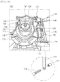
- the present invention provides a check valve including: a valve body 110 including an inlet 111 and an outlet 112 provided respectively on a first side and a second side thereof, with a passage 113 being provided between the inlet 111 and the outlet 112; a main disk 130 opening or closing the passage 113 by being rotated inside the valve body 110, with a flow hole 132 being formed through a portion of the main disk; an auxiliary disk 136 opening or closing the flow hole 132 of the main disk 130 by being rotated inside the valve body 110; an auxiliary disk shaft 138 functioning as a rotating shaft of the auxiliary disk 136, and being rotatably provided inside the valve body 110, with a longitudinal end thereof extending outside the valve body 110; and a shock-absorbing damper 150 being connected to the auxiliary disk shaft 138, and slowly closing the auxiliary disk 136 by exerting a force in a direction opposite to a closing direction of the auxiliary disk 136.
- the main disk 130 may be rotated about a main disc shaft 120 provided inside the valve body 110, or may be relative-rotatably coupled to the auxiliary disk shaft 138.
- the main disk 130 is connected to the auxiliary disk shaft 138 via a main disk connection arm 122, wherein the main disk connection arm 122 is configured such that an end thereof is formed in an annular ring shape, and the auxiliary disk shaft 138 is fitted into the annular ring-shaped end of the main disk connection arm 122, whereby the main disk 130 is independently rotatable about the auxiliary disk shaft 138.
- shock-absorbing damper 150 is connected to a rocker arm 153 protruding from an outer circumferential surface of the auxiliary disk shaft 138.
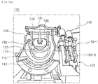
- the shock-absorbing damper 150 includes: a first shock-absorbing damper 150-1 that is provided on the valve body 110, and includes a first bumper 151-1 absorbing shock; a first shock-absorbing rod 152-1 connected to the first bumper 151-1 to transmit shock, and a first rocker arm 153-1 connected to the first shock-absorbing rod 152-1 at a first end thereof, and receiving torque from the auxiliary disk shaft 138 at a second end thereof; and a second shock-absorbing damper 150-2 that is provided on the valve body 110, and includes a second bumper 151-2 absorbing shock, a second shock-absorbing rod 152-2 connected to the second bumper 151-2 to transmit shock, and a second rocker arm 153-2 connected to the second shock-absorbing rod 152-2 at a first end thereof, and receiving torque from the auxiliary disk shaft 138 at a second end thereof, wherein a length of the second rocker arm 153-2 is relatively longer than a length of the first rocker arm 153-1 such that by a principle of a lever, a force transmitted to the
- the second rocker arm 153-2 is connected to the auxiliary disk shaft 138 at a location where the second rocker arm 153-2 is rotated higher than the first rocker arm 153-1.
- auxiliary disk shaft 138 is connected to a support rod 114 via a connection bar 116, wherein the connection bar 116 is formed in a bar shape with a through hole provided at each end thereof, and the auxiliary disk shaft 138 and the support rod 114 are inserted through associated through holes, respectively.
- a diameter of the through hole provided at an upper end of the connection bar 116 is larger than a diameter of the auxiliary disk shaft 138, and to prevent the connection bar 116 from being removed from the support rod 114, an end of the support rod 114 is provided with threads, and a nut 117 is engaged with the threaded end of the support rod 114 at a location outside the connection bar 116.
- the present invention configured as described above is advantageous in that it is provided with a main disk and a separate auxiliary disk, the main disk making a rapid closing operation, and the auxiliary disk, which has an area smaller than that of the main disk, making a slow closing operation, thereby not only reducing noise, vibration, and water hammer, but also reducing the amount of backflow.
- a check valve includes: a valve body 110; a main disc shaft 120; a main disc 130; an auxiliary disk 136; an auxiliary disk shaft 138; a balance weight 140; and a shock-absorbing damper 150, wherein the main disk 130 is configured to be closed quickly, and on the contrary, the auxiliary disk 136 is configured to be closed slowly.
- the valve body 110 is provided with an inlet 111 allowing a fluid to flow therein, and an outlet 112 allowing the fluid to be discharged therefrom, respectively at a front side and a back side thereof.
- the passage 113 is provided between the inlet 111 and the outlet 112.
- the inlet 111 and the outlet 112 are respectively connected to a water pipeline (see P in FIG. 1 ) so as to allow a fluid (that is, water) supplied through the water pipeline to flow through the inlet 111, the passage 113, and the outlet 112, wherein the check valve controls a flow of the fluid inside the water pipeline.
- the main disk 130 serves to open or close the passage 113 by being rotated inside the valve body 110, and is rotated about the main disc shaft 120.
- the main disc shaft 120 is mounted at opposite inner side walls of the valve body 110 through, for example, a bearing.
- the main disc shaft 120 is mounted to an upper portion of the main disk 130 to be in parallel with the main disc, and is connected to the main disk 120 via a main disk connection arm 122.
- the main disk connector 122 is configured to be in a bar shape, and opposite ends thereof are fixedly coupled to the main disk 130 and the main disc shaft 120, respectively, by a method such as welding or a key.
- the main disk 120 when the main disc shaft 120 is rotated, the main disk 120 is rotated, and the main disk 120 is opened by a fluid pressure increase in response to the operation of a pump and is closed by a fluid pressure decrease in response to the stopping of the pump, wherein the main disk 120 is closed quickly by the weight thereof and an outlet fluid pressure.
- a surface of the main disk 130 is provided with a flow hole 132 such that a predetermined amount of fluid flows in through the passage 113 for a predetermined time after the main disk 130 is completely closed, and the flow hole 132 is configured to be closed slowly by the auxiliary disk 136.
- the present invention is configured such that a flow hole 132 is formed through a portion of a surface of the main disk 130 to reduce noise and vibration when the main disk is closed by reducing the pressure applied to the main disk 130 through reducing the area of the main disk 130 that comes into contact with the fluid when it is closed.
- the outlet fluid presses the main disk 130 to be rotated and closed.
- the pressure applied to the main disk 130 is reduced, whereby even when the main disk 130 is quickly closed, it is possible to reduce shock exerted on the valve seat, and since the weight of the main disc 130 is reduced by the flow hole 132, the shock reduction effect becomes larger.
- the main disk 130 is quickly closed, it is possible to reduce the amount of backflow. Although some backflow occurs through the flow hole 132, the amount thereof is small, and the entire amount of the backflow is significantly reduced. As described above, the area of the flow hole 132 may be appropriately selected in order to reduce the shock when the main disk 130 is quickly closed while minimizing the amount of backflow through the flow hole 132.
- the check valve according to the present invention further includes the auxiliary disk 136 that closes the flow hole 132 of the main disk 130, and the auxiliary disk 136 is closed (slowly) later than the main disk 130.
- the auxiliary disk 136 is configured similar to the main disk 130, to open or close the flow hole 132 by a rotation thereof, and to achieve this, an upper portion of the auxiliary disk 136 is provided with the auxiliary disk shaft 138.
- the auxiliary disk shaft 138 is rotatably mounted inside the valve body 110 (more specifically, to an upper portion of the main disc shaft 120) via, for example, a bearing, and a longitudinal end thereof extends outside the valve body 110. Further, the auxiliary disk 136 and the auxiliary disk shaft 138 are coupled to each other via an auxiliary disk connection arm 137.
- the balance weight 140 rotates about the auxiliary disk shaft 138 by being connected to auxiliary disk shaft 138 outside the valve body 110, and thereby serves to rotate the auxiliary disk 136 so as to open and close the flow hole 132 of the main disk 130.
- the balance weight 140 includes: a rotation rod 141 for connection with the auxiliary disk shaft 138; and a weight member 142 having a predetermined weight, wherein a length of the rotation rod 141 and a weight of the weight member 142 may be determined according to the valve capacity, or the like.
- the shock-absorbing damper 150 is configured to exert a force in a direction opposite to a closing direction of the auxiliary disk 136, more specifically, in a direction opposite to a direction where the weight of the balance weight 140 is applied, when the auxiliary disk 136 is moved down, such that the balance weight 140 is moved down slowly to allow the auxiliary disk 136 to be closed slowly.
- the shock-absorbing damper is in the form of a hydraulic or a pneumatic cylinder.
- an end of a shock-absorbing rod 152 of the shock-absorbing damper 150 is connected to a rocker arm 153 protruding from an outer circumferential surface of the auxiliary disk shaft 138.
- a lower portion of the shock-absorbing damper 150 is rotatably hinged to a support rod 114 protruding from a lower outer side of the valve body 110.
- the lower portion of the shock-absorbing damper 150 is formed with a hinge block 115 with a hinge hole formed therethrough horizontally, wherein the support rod 114 is inserted through the hinge hole.
- auxiliary disk shaft 138 and the support rod 114 are connected to each other via a connection bar 116.
- the auxiliary disk shaft 138 may be deflected or twisted because it receives a large load while the auxiliary disk is rotated due to the pressure of fluid and a large load due to the load during rotation of the balance weight 140.
- the support rod 114 may also sag or bend due to the load of the shock-absorbing damper 150. Accordingly, when the auxiliary disk shaft 138 and the support rod 114 are connected to each other via the connection bar 116, it is possible to prevent bend of the auxiliary disk shaft 138 and the support rod 114.
- connection bar 116 is formed in a bar shape extending in a longitudinal direction thereof with a through hole provided at each end thereof, and the auxiliary disk shaft 138 and the support rod 114 are inserted through associated through holes, respectively.
- a diameter of the through hole provided at an upper end of the connection bar 116 is larger than a diameter of the auxiliary disk shaft 138, so as not to interfere with the rotation of the auxiliary disk shaft 138.
- an end of the support rod 114 is provided with threads, and a nut 117 is engaged with the threaded end of the support rod 114 at a location outside the connection bar 116, thereby preventing the connection bar 116 from being removed from the support rod 114.
- the main disk 130 is rotatably coupled to the separate main disc shaft 120, but according to another embodiment of the present invention, without the separate main disc shaft 120, the main disk can be relative-rotatably coupled to the auxiliary disk shaft 138.
- an end of the auxiliary disk connection arm 137 may be welded on an outer circumferential surface of the auxiliary disk shaft 138, or may be formed in an annular ring shape such that after the auxiliary disk shaft 138 is inserted thereinto, and is fixedly coupled by a key, whereby the auxiliary disk shaft 138 is rotated along with the auxiliary disk 136.
- the main disk connection arm 122 is configured such that an end thereof is formed in an annular ring shape, and the auxiliary disk shaft 138 is fitted into the annular ring-shaped end without using a key, whereby the main disk 130 is independently rotatable. Accordingly, the main disk 130 is rotated independently of the rotation of the auxiliary disk shaft 138 and can make a quick closing operating without being affected by the shock-absorbing damper 150.
- the shock-absorbing dampers 150 includes a first shock-absorbing damper 150-1 and a second shock-absorbing damper 150-2 which are disposed in parallel to each other.
- the shock-absorbing damper 150 may be in the form of a single cylinder, but as in the embodiment, the case where two cylinders are disposed in parallel to each other allows precise control of the speed of opening and closing the auxiliary disk 136.
- the parallel-type shock-absorbing damper 150 includes the first shock-absorbing damper 150-1 and the second shock-absorbing damper 150-2, wherein the first shock-absorbing damper 150-1 and the second shock-absorbing damper 150-2 are connected to the auxiliary disk shaft 138 extending outside the valve body 110.
- the first shock-absorbing damper 150-1 includes a first bumper 151-1, a first shock-absorbing rod 152-1, and a first rocker arm 153-1.
- the second shock-absorbing damper 150-2 includes a second bumper 151-2, a second shock-absorbing rod 152-2, and a second rocker arm 153-2.
- the first bumper 151-1 and the second bumper 151-2 serve to provide buffer power, and the first shock-absorbing rod 152-1 and the second shock-absorbing rod 152-2 are connected respectively to the first bumper 151-1 and the second bumper 151-2 so as to transmit torque of the auxiliary disk shaft 138 thereto.
- the first shock-absorbing damper 150-1 may be in the form of a hydraulic or a pneumatic cylinder device.
- the first bumper 151-1 is a cylinder; and the first shock-absorbing rod 152-1 is a cylinder rod connected to the cylinder.
- a first pressure regulating valve 154-1 is generally provided in the damper.
- the pressure regulating valve 154-1 is also referred as an 'oil (air) flow control valve', and serves to regulate internal pressure of the cylinder caused by oil (air) pressure inside the cylinder.
- the first bumper 151-1 is locked outside the valve body 110.
- the first bumper may be locked to the support rod 114 that is provided at a lower portion outside the valve body 110.
- the first bumper may be locked to a bottom.
- the first shock-absorbing rod 152-1 performs a linear reciprocating motion in which the first shock-absorbing rod moves to the inside of a body of the first bumper 151-1 or moves from the inside of the body of the second bumper 151-2 to the outside thereof.
- hydraulic pressure or pneumatic pressure is applied to the first shock-absorbing rod 152-1, it is possible to allow the balance weight 140 to move slowly by a buffering effect. Thereby, it is possible to allow slow closing of the auxiliary disk 136.
- the first rocker arm 153-1 is configured such that a first end thereof is connected to the first shock-absorbing rod 152-1, and a second end thereof is locked to the auxiliary disk shaft 138.
- the second bumper 151-2 of the second shock-absorbing damper 150-2 may be in the form of a hydraulic or a pneumatic cylinder, and is locked outside the valve body 110.
- second bumper 151-2 may be provided next to the first bumper 151-1 so as to be in parallel to each other.
- the second bumper 151-2 is provided with a pressure regulating valve 154-2.
- the second shock-absorbing rod 152-2 performs a linear reciprocating motion in which the second shock-absorbing rod moves to the inside of a body of the second bumper 151-2 or moves from the inside of the body of the second bumper 151-2 to the outside thereof, and allows the auxiliary disk 136 to be closed slowly in cooperation with the first shock-absorbing rod 152-1.
- the second rocker arm 153-2 is configured such that a first end thereof is connected to the second shock-absorbing rod 152-2, and a second end thereof is locked to the auxiliary disk shaft 138.
- the second rocker arm 153-2 is disposed next to the first rocker arm 153-1 so as to be parallel to each other.
- the second rocker arm 153-2 of the second shock-absorbing damper 150-2 is longer than the first rocker arm 153-1 of the first shock-absorbing damper 150-1. This is because by using two shock-absorbing dampers 150 and by using the principle of a lever, it is possible to produce an effect of using more than two shock-absorbing dampers 150.
- a force applied to the second shock-absorbing rod 152-2 by the second rocker arm 153-2 is 5, and a force applied to the first shock-absorbing rod 152-1 by the first rocker arm 153-1 is 10.
- the exerting force and the length are inversely related.
- the auxiliary disk shaft 138 corresponds to a fulcrum, and each of the first rocker arm 153-1 and the second rocker arm 153-2 locked to the auxiliary disk shaft 128 serves as a lever. Therefore, when the second rocker arm 153-2 is configured to be longer than the first rocker arm 153-1, a force applied by the first rocker arm 153-1 is larger than that applied by the second rocker arm 153-2 when the auxiliary disk shaft 138 rotates.
- the force applied to the second shock-absorbing rod 152-2 by the second rocker arm 153-2 is relatively smaller than the force applied to the first shock-absorbing rod 152-1 by the first rocker arm 153-1.
- the present invention provides effect of slow closing of the auxiliary disk 136, which is more than that produced by simply using two cylinders.
- the second rocker arm 153-2 having a length longer than the first rocker arm 153-1 is connected to the auxiliary disk shaft 138 at a location where the second rocker arm is rotated higher than the first rocker arm.
- FIG. 7 schematically shows operational views of the check valve configured as described above. As shown in FIG. 7a , when the pump is initially operated and the fluid flows in the forward direction, both the main disk 130 and the auxiliary disk 136 are opened.
- the main disk 130 When the fluid is not supplied due to the sudden stop of the pump, as shown in FIG. 7b , the main disk 130 is closed at a relatively raid speed to minimize the amount of backflow, and the auxiliary disk 136 is closed relatively slowly to reduce the increase in the backflow velocity and shock caused by quick closing of the main disk 130. In this case, a small amount of the fluid flows back through the flow hole 132, thereby reducing the pressure applied to the main disk 130, so it is possible to prevent a slam due to quick closing of the valve.
- FIG. 7c shows a state where the main disk 130 is completely closed and the auxiliary disk 136 is being closed slowly; and FIG. 7d shows a state where both the main disk 130 and the auxiliary disk 136 are completely closed.
- FIG. 8 shows a graph (a) of changes in degrees of opening over time in a conventional check valve, in which a main disk and an auxiliary disk are closed slowly (the case of providing a shock-absorbing damper, such as a cylinder, to each of the main disk and the auxiliary disk), and a graph (b) of changes in degrees of opening over time in the check valve provided with an auxiliary disk for slow closing according to the present invention.
- the check valve in which the main disk and the auxiliary disk are closed slowly, is closed slowly in a nearly constant speed over time, so the slope of the graph is moderate, and in the graph, the area A formed by crossing the time axis (X axis) and the opening axis (Y axis) is relatively large.
- the large area A means that the valve is open for a long period of time, which means that the amount of backflow is large and the backflow velocity is also greatly increased.
- the graph is derived as shown in FIG. 8b , and in the graph, the area B formed by crossing the time axis (X axis) and the opening axis (Y axis) is relatively considerably smaller than the area A.
- the amount of backflow is considerably reduced compared with the conventional check valve, in which the main disk and the auxiliary disk are closed slowly.
- the main disk 130 is closed quickly to minimize the amount of backflow, and the auxiliary disk 136 is closed slowly to prevent noise, vibration, and water hammer due to shock caused when the valve is closed, whereby it is possible to compensate for disadvantages of all of the conventional quick-closing check valve, the slow-closing check valve, and the check valve, in which a main disk and an auxiliary disk are closed slowly.
Landscapes
- Engineering & Computer Science (AREA)
- General Engineering & Computer Science (AREA)
- Mechanical Engineering (AREA)
- Check Valves (AREA)
- Details Of Valves (AREA)
Applications Claiming Priority (2)
| Application Number | Priority Date | Filing Date | Title |
|---|---|---|---|
| KR1020140175290A KR101538728B1 (ko) | 2014-12-08 | 2014-12-08 | 슬램 및 수충격 방지용 체크밸브 |
| PCT/KR2015/012621 WO2016093511A1 (ko) | 2014-12-08 | 2015-11-24 | 슬램 및 수충격 방지용 체크밸브 |
Publications (2)
| Publication Number | Publication Date |
|---|---|
| EP3232100A1 true EP3232100A1 (de) | 2017-10-18 |
| EP3232100A4 EP3232100A4 (de) | 2018-08-22 |
Family
ID=53876011
Family Applications (1)
| Application Number | Title | Priority Date | Filing Date |
|---|---|---|---|
| EP15866705.5A Withdrawn EP3232100A4 (de) | 2014-12-08 | 2015-11-24 | Rückschlagventil zur verhinderung von absperrung und wasserschlag |
Country Status (6)
| Country | Link |
|---|---|
| US (1) | US10253895B2 (de) |
| EP (1) | EP3232100A4 (de) |
| KR (1) | KR101538728B1 (de) |
| CN (1) | CN107002893B (de) |
| SA (1) | SA517381682B1 (de) |
| WO (1) | WO2016093511A1 (de) |
Families Citing this family (13)
| Publication number | Priority date | Publication date | Assignee | Title |
|---|---|---|---|---|
| KR101487748B1 (ko) * | 2014-05-19 | 2015-01-30 | 플로우테크 주식회사 | 병렬 실린더형 체크밸브 |
| EP3298311B1 (de) * | 2015-05-07 | 2020-02-19 | Emerson Process Management Regulator Technologies, Inc. | Absperrventil mit niedrigflussbegrenzung mit verschlussfunktionalität bei übermässigem fluss |
| KR101609591B1 (ko) * | 2015-08-24 | 2016-04-06 | 플로우테크 주식회사 | 이젝터 효과를 이용한 수충격 완화 기능을 구비하는 수배관 시스템 및 이를 위한 압력탱크 연결구 |
| KR101722078B1 (ko) | 2015-09-18 | 2017-03-31 | 플로우테크 주식회사 | 수배관 시스템 및 그 제어 방법 |
| KR101722073B1 (ko) | 2015-09-18 | 2017-03-31 | 플로우테크 주식회사 | 체크밸브의 슬램 완화 기능을 구비하는 수배관 시스템 |
| KR101673495B1 (ko) | 2016-03-30 | 2016-11-07 | 플로우테크 주식회사 | 체크밸브 슬램 및 수충격 방지용 제어디스크를 구비하는 수배관 시스템 및 이를 위한 압력탱크 연결구 |
| ES2677256B1 (es) * | 2017-01-31 | 2019-05-27 | Sener Ing & Sist | Válvula unidireccional para un dispositivo de captación de energía de las olas |
| KR20180099053A (ko) | 2017-02-28 | 2018-09-05 | 양재구 | 체크밸브 슬램 및 수충격 방지용 회동댐퍼를 구비하는 수배관 시스템 및 이를 위한 압력탱크 연결구 |
| KR101790750B1 (ko) | 2017-03-15 | 2017-10-26 | 플로우테크 주식회사 | 체크밸브의 슬램 완화 기능을 구비하는 수배관 시스템 |
| EP3499105B1 (de) * | 2017-12-15 | 2020-05-27 | Hamilton Sundstrand Corporation | Rückschlagventile |
| KR102532956B1 (ko) | 2020-11-26 | 2023-05-16 | 플로우테크 주식회사 | 압력탱크 이상 감지 및 슬램 방지 기능을 구비하는 듀얼 탱크 수배관 시스템 |
| KR20220073494A (ko) | 2020-11-26 | 2022-06-03 | 플로우테크 주식회사 | 듀얼 탱크와 제어디스크를 구비하는 수배관 시스템 |
| KR20220073492A (ko) | 2020-11-26 | 2022-06-03 | 플로우테크 주식회사 | 듀얼 탱크와 이젝터 효과를 이용한 수충격 완화 기능을 구비하는 수배관 시스템 |
Family Cites Families (17)
| Publication number | Priority date | Publication date | Assignee | Title |
|---|---|---|---|---|
| JPS60151473A (ja) | 1984-01-18 | 1985-08-09 | Kurimoto Iron Works Ltd | 親子式バタフライ形逆止弁 |
| JPS6194664A (ja) | 1984-10-15 | 1986-05-13 | テルモ株式会社 | 穿刺用栓体 |
| US4693269A (en) * | 1985-10-04 | 1987-09-15 | Yutaka Yamada | Check valve assembly for pipeline system |
| KR890001586Y1 (ko) * | 1985-12-26 | 1989-04-06 | 박명기 | 부관작용을 겸한 버터프라이밸브 |
| GB8630824D0 (en) | 1986-12-23 | 1987-02-04 | Ici Plc | Pyrimidine derivatives |
| JP3487372B2 (ja) | 1994-11-07 | 2004-01-19 | 株式会社熊谷鉄工所 | スイング式逆止め弁 |
| US5746246A (en) * | 1994-12-05 | 1998-05-05 | Kabushiki Kaisha Yokota Seisakusho | Water hammer preventing check valve |
| US5957428A (en) | 1995-11-13 | 1999-09-28 | Kabushiki Kaisha Yokota Seisakusho | Composite-action butterfly valve |
| KR200170011Y1 (ko) | 1997-04-21 | 2000-03-02 | 김승문 | 회전식2속감쇄체크밸브 |
| US6543474B2 (en) * | 2001-05-01 | 2003-04-08 | Roy A. Fetterman, Jr. | Pressure equalizing check valve |
| KR100567927B1 (ko) * | 2005-09-14 | 2006-04-05 | 주식회사 삼진정밀 | 공기흡배기부를 갖는 체크밸브 |
| KR101302581B1 (ko) | 2011-01-12 | 2013-09-02 | 한국수력원자력 주식회사 | 유압완충식 틸팅 디스크 역지밸브 |
| CN202109038U (zh) | 2011-06-27 | 2012-01-11 | 精工阀门有限公司 | 新型缓闭止回阀 |
| CN202252157U (zh) | 2011-06-30 | 2012-05-30 | 上海欧特莱阀门机械有限公司 | 一种新型静音缓闭蝶式止回阀 |
| KR101375280B1 (ko) | 2012-04-06 | 2014-03-17 | 프리시스 주식회사 | 게이트 밸브 |
| CN203067862U (zh) * | 2013-01-22 | 2013-07-17 | 铁岭方众阀门有限公司 | 子母阀板式旋启止回阀 |
| KR101487748B1 (ko) | 2014-05-19 | 2015-01-30 | 플로우테크 주식회사 | 병렬 실린더형 체크밸브 |
-
2014
- 2014-12-08 KR KR1020140175290A patent/KR101538728B1/ko not_active Expired - Fee Related
-
2015
- 2015-11-24 WO PCT/KR2015/012621 patent/WO2016093511A1/ko not_active Ceased
- 2015-11-24 EP EP15866705.5A patent/EP3232100A4/de not_active Withdrawn
- 2015-11-24 US US15/528,107 patent/US10253895B2/en active Active
- 2015-11-24 CN CN201580066483.8A patent/CN107002893B/zh not_active Expired - Fee Related
-
2017
- 2017-06-07 SA SA517381682A patent/SA517381682B1/ar unknown
Also Published As
| Publication number | Publication date |
|---|---|
| KR101538728B1 (ko) | 2015-07-24 |
| CN107002893B (zh) | 2019-01-22 |
| CN107002893A (zh) | 2017-08-01 |
| SA517381682B1 (ar) | 2021-06-15 |
| US10253895B2 (en) | 2019-04-09 |
| WO2016093511A1 (ko) | 2016-06-16 |
| US20170328485A1 (en) | 2017-11-16 |
| EP3232100A4 (de) | 2018-08-22 |
Similar Documents
| Publication | Publication Date | Title |
|---|---|---|
| US10253895B2 (en) | Check valve for preventing slam and water hammer | |
| CN111720593B (zh) | 一种多功能止回阀 | |
| CA2947551C (en) | Parallel cylinder-type check valve | |
| JPWO1997038249A1 (ja) | 可変バイパス緩閉式逆止弁装置 | |
| CN106949255B (zh) | 一种筒塞平衡式流量控制阀 | |
| WO1997038249A1 (fr) | Dispositif a valve de non-retour variable et a fermeture lente, montee en derivation | |
| EP2414716B1 (de) | Verfahren zur betätigung eines ventils | |
| KR101117540B1 (ko) | 체크밸브 | |
| RU2388955C2 (ru) | Запорно-дросселирующий клапан | |
| US10746308B2 (en) | Valve apparatus and controlling method therefor | |
| CN208503504U (zh) | 蝶阀 | |
| KR101605965B1 (ko) | 내부 완충식 역지밸브 | |
| CN109578636A (zh) | 一种可调式止回阀 | |
| KR101523955B1 (ko) | 가변 교축에 의해 급폐 및 완폐의 조절이 가능한 체크밸브 | |
| JPS5848763B2 (ja) | アクチュエ−タのブレ−キ回路 | |
| CN217898817U (zh) | 内置湍流多锥孔临界自阻尼结构的蝶阀 | |
| KR102081640B1 (ko) | 수충격 제어 및 에너지 절감형 유압식 볼밸브 | |
| KR20120008357U (ko) | 버터플라이 밸브 | |
| US12392424B2 (en) | Flow regulator | |
| CN207145686U (zh) | 一种斜盘止回阀的缓闭装置 | |
| HK40127925A (zh) | 车门摆动驱动器 | |
| CN222836377U (zh) | 一种大口径快速开关球阀阻尼油缸结构 | |
| OA18022A (en) | Parallel cylinder type check valve. | |
| CN217898818U (zh) | 内置多孔消声自阻尼结构的蝶阀 | |
| CN102305263B (zh) | 减振器的阻尼调节机构 |
Legal Events
| Date | Code | Title | Description |
|---|---|---|---|
| STAA | Information on the status of an ep patent application or granted ep patent |
Free format text: STATUS: THE INTERNATIONAL PUBLICATION HAS BEEN MADE |
|
| PUAI | Public reference made under article 153(3) epc to a published international application that has entered the european phase |
Free format text: ORIGINAL CODE: 0009012 |
|
| STAA | Information on the status of an ep patent application or granted ep patent |
Free format text: STATUS: REQUEST FOR EXAMINATION WAS MADE |
|
| 17P | Request for examination filed |
Effective date: 20170608 |
|
| AK | Designated contracting states |
Kind code of ref document: A1 Designated state(s): AL AT BE BG CH CY CZ DE DK EE ES FI FR GB GR HR HU IE IS IT LI LT LU LV MC MK MT NL NO PL PT RO RS SE SI SK SM TR |
|
| AX | Request for extension of the european patent |
Extension state: BA ME |
|
| DAV | Request for validation of the european patent (deleted) | ||
| DAX | Request for extension of the european patent (deleted) | ||
| A4 | Supplementary search report drawn up and despatched |
Effective date: 20180723 |
|
| RIC1 | Information provided on ipc code assigned before grant |
Ipc: F16K 17/34 20060101ALI20180717BHEP Ipc: F16K 47/04 20060101ALI20180717BHEP Ipc: F16K 15/03 20060101AFI20180717BHEP Ipc: F16K 47/02 20060101ALI20180717BHEP |
|
| STAA | Information on the status of an ep patent application or granted ep patent |
Free format text: STATUS: THE APPLICATION IS DEEMED TO BE WITHDRAWN |
|
| 18D | Application deemed to be withdrawn |
Effective date: 20190220 |