EP3232180A1 - Dispositif d'analyse optique in situ d'un gaz - Google Patents
Dispositif d'analyse optique in situ d'un gaz Download PDFInfo
- Publication number
- EP3232180A1 EP3232180A1 EP16165648.3A EP16165648A EP3232180A1 EP 3232180 A1 EP3232180 A1 EP 3232180A1 EP 16165648 A EP16165648 A EP 16165648A EP 3232180 A1 EP3232180 A1 EP 3232180A1
- Authority
- EP
- European Patent Office
- Prior art keywords
- gas
- measuring
- openings
- light
- housing
- Prior art date
- Legal status (The legal status is an assumption and is not a legal conclusion. Google has not performed a legal analysis and makes no representation as to the accuracy of the status listed.)
- Granted
Links
- 238000004868 gas analysis Methods 0.000 title abstract 2
- 238000011065 in-situ storage Methods 0.000 title abstract 2
- 238000011156 evaluation Methods 0.000 abstract 2
- 230000003287 optical effect Effects 0.000 abstract 2
Images


Classifications
-
- F—MECHANICAL ENGINEERING; LIGHTING; HEATING; WEAPONS; BLASTING
- F16—ENGINEERING ELEMENTS AND UNITS; GENERAL MEASURES FOR PRODUCING AND MAINTAINING EFFECTIVE FUNCTIONING OF MACHINES OR INSTALLATIONS; THERMAL INSULATION IN GENERAL
- F16K—VALVES; TAPS; COCKS; ACTUATING-FLOATS; DEVICES FOR VENTING OR AERATING
- F16K7/00—Diaphragm valves or cut-off apparatus, e.g. with a member deformed, but not moved bodily, to close the passage ; Pinch valves
- F16K7/02—Diaphragm valves or cut-off apparatus, e.g. with a member deformed, but not moved bodily, to close the passage ; Pinch valves with tubular diaphragm
- F16K7/04—Diaphragm valves or cut-off apparatus, e.g. with a member deformed, but not moved bodily, to close the passage ; Pinch valves with tubular diaphragm constrictable by external radial force
- F16K7/07—Diaphragm valves or cut-off apparatus, e.g. with a member deformed, but not moved bodily, to close the passage ; Pinch valves with tubular diaphragm constrictable by external radial force by means of fluid pressure
-
- G—PHYSICS
- G01—MEASURING; TESTING
- G01N—INVESTIGATING OR ANALYSING MATERIALS BY DETERMINING THEIR CHEMICAL OR PHYSICAL PROPERTIES
- G01N1/00—Sampling; Preparing specimens for investigation
- G01N1/28—Preparing specimens for investigation including physical details of (bio-)chemical methods covered elsewhere, e.g. G01N33/50, C12Q
- G01N1/40—Concentrating samples
- G01N1/4077—Concentrating samples by other techniques involving separation of suspended solids
-
- G—PHYSICS
- G01—MEASURING; TESTING
- G01N—INVESTIGATING OR ANALYSING MATERIALS BY DETERMINING THEIR CHEMICAL OR PHYSICAL PROPERTIES
- G01N1/00—Sampling; Preparing specimens for investigation
- G01N1/02—Devices for withdrawing samples
- G01N1/22—Devices for withdrawing samples in the gaseous state
- G01N1/2202—Devices for withdrawing samples in the gaseous state involving separation of sample components during sampling
- G01N1/2205—Devices for withdrawing samples in the gaseous state involving separation of sample components during sampling with filters
-
- G—PHYSICS
- G01—MEASURING; TESTING
- G01N—INVESTIGATING OR ANALYSING MATERIALS BY DETERMINING THEIR CHEMICAL OR PHYSICAL PROPERTIES
- G01N1/00—Sampling; Preparing specimens for investigation
- G01N1/02—Devices for withdrawing samples
- G01N1/22—Devices for withdrawing samples in the gaseous state
- G01N1/2247—Sampling from a flowing stream of gas
-
- G—PHYSICS
- G01—MEASURING; TESTING
- G01N—INVESTIGATING OR ANALYSING MATERIALS BY DETERMINING THEIR CHEMICAL OR PHYSICAL PROPERTIES
- G01N21/00—Investigating or analysing materials by the use of optical means, i.e. using sub-millimetre waves, infrared, visible or ultraviolet light
- G01N21/17—Systems in which incident light is modified in accordance with the properties of the material investigated
- G01N21/25—Colour; Spectral properties, i.e. comparison of effect of material on the light at two or more different wavelengths or wavelength bands
- G01N21/27—Colour; Spectral properties, i.e. comparison of effect of material on the light at two or more different wavelengths or wavelength bands using photo-electric detection ; circuits for computing concentration
- G01N21/274—Calibration, base line adjustment, drift correction
- G01N21/276—Calibration, base line adjustment, drift correction with alternation of sample and standard in optical path
-
- G—PHYSICS
- G01—MEASURING; TESTING
- G01N—INVESTIGATING OR ANALYSING MATERIALS BY DETERMINING THEIR CHEMICAL OR PHYSICAL PROPERTIES
- G01N21/00—Investigating or analysing materials by the use of optical means, i.e. using sub-millimetre waves, infrared, visible or ultraviolet light
- G01N21/17—Systems in which incident light is modified in accordance with the properties of the material investigated
- G01N21/25—Colour; Spectral properties, i.e. comparison of effect of material on the light at two or more different wavelengths or wavelength bands
- G01N21/31—Investigating relative effect of material at wavelengths characteristic of specific elements or molecules, e.g. atomic absorption spectrometry
- G01N21/35—Investigating relative effect of material at wavelengths characteristic of specific elements or molecules, e.g. atomic absorption spectrometry using infrared light
- G01N21/3504—Investigating relative effect of material at wavelengths characteristic of specific elements or molecules, e.g. atomic absorption spectrometry using infrared light for analysing gases, e.g. multi-gas analysis
-
- G—PHYSICS
- G01—MEASURING; TESTING
- G01N—INVESTIGATING OR ANALYSING MATERIALS BY DETERMINING THEIR CHEMICAL OR PHYSICAL PROPERTIES
- G01N21/00—Investigating or analysing materials by the use of optical means, i.e. using sub-millimetre waves, infrared, visible or ultraviolet light
- G01N21/17—Systems in which incident light is modified in accordance with the properties of the material investigated
- G01N21/47—Scattering, i.e. diffuse reflection
- G01N21/49—Scattering, i.e. diffuse reflection within a body or fluid
- G01N21/53—Scattering, i.e. diffuse reflection within a body or fluid within a flowing fluid, e.g. smoke
- G01N21/534—Scattering, i.e. diffuse reflection within a body or fluid within a flowing fluid, e.g. smoke by measuring transmission alone, i.e. determining opacity
-
- G—PHYSICS
- G01—MEASURING; TESTING
- G01N—INVESTIGATING OR ANALYSING MATERIALS BY DETERMINING THEIR CHEMICAL OR PHYSICAL PROPERTIES
- G01N33/00—Investigating or analysing materials by specific methods not covered by groups G01N1/00 - G01N31/00
- G01N33/0004—Gaseous mixtures, e.g. polluted air
- G01N33/0006—Calibrating gas analysers
-
- G—PHYSICS
- G01—MEASURING; TESTING
- G01N—INVESTIGATING OR ANALYSING MATERIALS BY DETERMINING THEIR CHEMICAL OR PHYSICAL PROPERTIES
- G01N33/00—Investigating or analysing materials by specific methods not covered by groups G01N1/00 - G01N31/00
- G01N33/0004—Gaseous mixtures, e.g. polluted air
- G01N33/0009—General constructional details of gas analysers, e.g. portable test equipment
- G01N33/0027—General constructional details of gas analysers, e.g. portable test equipment concerning the detector
- G01N33/0036—General constructional details of gas analysers, e.g. portable test equipment concerning the detector specially adapted to detect a particular component
- G01N33/0044—Sulphides, e.g. H2S
-
- G—PHYSICS
- G01—MEASURING; TESTING
- G01N—INVESTIGATING OR ANALYSING MATERIALS BY DETERMINING THEIR CHEMICAL OR PHYSICAL PROPERTIES
- G01N1/00—Sampling; Preparing specimens for investigation
- G01N1/28—Preparing specimens for investigation including physical details of (bio-)chemical methods covered elsewhere, e.g. G01N33/50, C12Q
- G01N1/40—Concentrating samples
- G01N1/4077—Concentrating samples by other techniques involving separation of suspended solids
- G01N2001/4088—Concentrating samples by other techniques involving separation of suspended solids filtration
-
- G—PHYSICS
- G01—MEASURING; TESTING
- G01N—INVESTIGATING OR ANALYSING MATERIALS BY DETERMINING THEIR CHEMICAL OR PHYSICAL PROPERTIES
- G01N21/00—Investigating or analysing materials by the use of optical means, i.e. using sub-millimetre waves, infrared, visible or ultraviolet light
- G01N21/17—Systems in which incident light is modified in accordance with the properties of the material investigated
- G01N21/47—Scattering, i.e. diffuse reflection
- G01N21/49—Scattering, i.e. diffuse reflection within a body or fluid
- G01N21/53—Scattering, i.e. diffuse reflection within a body or fluid within a flowing fluid, e.g. smoke
- G01N21/534—Scattering, i.e. diffuse reflection within a body or fluid within a flowing fluid, e.g. smoke by measuring transmission alone, i.e. determining opacity
- G01N2021/536—Measurement device mounted at stack
Definitions
- the invention relates to a device for optical in-situ gas analysis according to the preamble of claim 1.
- Areas of application include, for example, emission measurements of industrial plants, where the exhaust gases in an exhaust duct must be monitored for their content of certain molecular compounds.
- the gas streams to which the optoelectronic device is exposed to measure the desired gas fractions are characterized by high particulate loads, such as smoke, dusts or other aerosols. These high particle loads cause a high light absorption and / or a high light scattering, which makes the actual measurement much hindered or impossible.
- hydrogen sulfide has a very broad absorption as well as ultrafine dust. It can then no longer be distinguished whether the absorption is due to the hydrogen sulfide or the dust.
- test gas must be introduced into the measuring section.
- the test gas is blown into the measuring section.
- the test section is not hermetically sealed, but the test gas escapes through the pores of the filter in the exhaust duct.
- a sufficient amount of test gas must be injected into the measuring section permanently with sufficient pressure.
- the amount of test gas required for a calibration is correspondingly high, which causes correspondingly high costs. This disadvantage is particularly noticeable in long measurement distances with a correspondingly long, porous filter.
- the measuring lance has an outer tube, wherein the outer tube has openings for the gas to be measured.
- the openings are for the test phase Closable with at least one seal, the seal sealingly closes the openings by increasing their volume.
- the openings to the measuring section are closed in a simple manner, so that no measuring gas can get into the measuring section. Then the measuring section can be flooded with test gas.
- a defined leak through a drain valve or a defined leak, but which may be small, makes sense to displace the measurement gas still present after closing the openings by the test gas from the measuring section.
- the test gas can escape only through the small defined leak and not through the filter.
- a test gas filling of the measuring section is achieved.
- the test gas consumption is calculable and can be significantly minimized and is also largely independent of the length of the active measuring section.
- the measuring section is also filled evenly with test gas. The test gas consumption is constant and predictable.
- the seals of the device according to the invention require no classical moving parts, resulting in little wear and a long life. There are only a few components necessary.
- the seal is structurally very simple and large opening areas are possible, which allow a better gas exchange. Due to the expansible seal a large tolerance compensation is possible.
- test mode could be performed automatically in defined time intervals or by manual operation. This would be reflected in price graduated variants of the device according to the invention.
- volume change takes place with pneumatic or hydraulic means, for example by means of an associated pump.
- a gas-permeable filter is provided, through which the measuring gas passes into the measuring section.
- the filter consists for example of a piece of pipe made of porous material and is held with a suitable support structure. Inside the filter is the measuring section. Due to the porous structure, the gas to be measured can enter the measuring section, but depending on the pore size, particles can be prevented.
- test gas connection is provided on the measuring lance or the housing in order to be able to fill the measuring section with a test gas via it.
- the test gas could be used in one embodiment of the invention at the same time as a propellant gas for the seals.
- a heating coil on the outside of the outer tube can prevent the ingress of water when used in a wet sample gas.
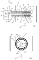
- An optoelectronic device 10 for the optical in-situ gas analysis of a gas stream 28, which is guided in an exhaust gas channel 26, has an in Fig. 1 illustrated first embodiment, a light emitter 12, which emits a transmitted light beam 14.
- the transmitted light beam 14 defines a measuring path 16 and is received by a light receiver 22 after reflection at a retroreflector 18 and a divider mirror 20.
- the light receiver 22 generates, as a function of the incident light, received signals which are evaluated in an evaluation device 24, for example in order to determine the concentration of a component of the measurement gas.
- Such an optoelectronic device 10 is formed in this embodiment as a transmissiometer, so that with the light receiver 22, the intensity of the light passing through the measuring section 16 is measured.
- the light emitter 12 is tuned to a specific wavelength, which is absorbed by a gas component to be examined, for example hydrogen sulfide.
- a statement can then be made as to how high the concentration of the gas fraction of interest in the gas stream 28 is that is guided in the exhaust gas channel 26.
- the optoelectronic device 10 comprises a housing 29, with a measuring lance 30, whose first end 32 is connected to the housing 29 and which projects with its other second end 34 into the exhaust gas channel 26 and thus into the gas 28 to be measured.
- Housing 29 and measuring lance 30 are fixed via a mounting flange 36 on a wall of the exhaust passage.
- the optoelectronic units such as light emitter 12, light receiver 22 and evaluation 24 are arranged, and in the measuring lance 30, the light is guided through the measuring section 16.
- the retroreflector 18 is held in a reflector housing.
- the measuring lance 30 has an outer tube 40 that extends over the entire length of the measuring lance 30 and is fixed at one end to the housing 29 and holds at its other end the retroreflector 18. In the region of the outer tube 40, which projects into the exhaust gas channel 26, the outer tube 40 openings 42, so that portions of the gas stream 28 can get into the measuring section 16.
- the guided in the exhaust duct 26 gas stream 28, which is indicated only by an arrow 28 may be loaded with particles, such as dust, smoke or other aerosols, the particles interfere with the actual optical measurement on the measuring section 16.
- a gas-permeable filter 44 preferably of porous material, is provided at least in the region of the openings 42. In the embodiment according to Fig. 1 and 2 is the filter 44 on the outside of the outer tube 40th
- the inner tube 46 has the same length as the outer tube 40.
- the interior of the inner tube 46 is divided by a sealing window 50 into two parts. In the first part, which faces the housing 29, no measurement gas and thus no contamination from the second, the reflector 18 facing part can pass. In the second part, which is located at the reflector-side end of the inner tube 46, the inner tube 46 has openings 54, through which the measurement gas 28 can reach the measuring section 16.
- the openings 42 in the outer tube 40 are in this embodiment as two larger slot openings 42-1 and 42-2 (FIGS. Fig. 2 ), through which the measurement gas 28 can enter and exit via the filter 44. Through the openings 54 in the inner tube 46, the measurement gas 28 can then reach into the measuring section 16.
- the two openings 42-1 and 42-2 of the outer tube 40 can be sealed according to the invention, each with a seal 60-1 and 60-2 (hereinafter also referred to simply as "seal 60").
- the seal 60 is made a strip of elastic material adapted in the form of the oblong opening 42, the strip being variable in its volume. This volume change may be pneumatically or hydraulically or in a comparable manner and driven by a corresponding actuator 62, for example a pump.
- the seals 60 are in the unexpanded state and supply the openings 42 or 42-1 and 42- 2 free. This is in Fig. 1 and 2 shown.
- the seals 60 are in the expanded state and close the openings 42 and 42-1, 42 -2. This is in the 3 and 4 shown.
- a test gas connection 59 is provided, via which test gas can be passed into the outer and inner tubes, so that the remaining measuring gas can be displaced out of the measuring section 16.
- test gas can be passed into the outer and inner tubes, so that the remaining measuring gas can be displaced out of the measuring section 16.
- test gas it is necessary that so much test gas is filled that the pressure in the measuring section 16 is slightly higher than in the exhaust passage 26.
- a defined leak is provided so that sample gas from the inner and outer tube and thus from the measuring section 16 "rinsed" is.
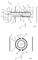
- Fig. 5 shows a very similar embodiment as that of the Fig. 1 to 4
- the modification is merely that the filter 44 is still disposed within the inner tube 46.
- the tube cross-section can be arbitrary in principle, for example, round, polygonal, oval or the like.
- the measuring section 16 is located inside the filter 44, which is suitably held in the outer tube 40. This is done here by the filter 44 is the end face on the one hand by a wall 51, in which the window 50 is arranged, and on the other hand held by the reflector housing. In this way it is also ensured that the measurement gas can only pass through the filter 44 into the measurement path.
- the seals 60 are now, as in the cross section of Fig. 7 can be seen on the outer tube 40 arranged alongside the openings 42-1 and 42-2.
- two seals 60-3 and 60-4 or 60-5 and 60-6 are provided for each opening, which increase in volume in the direction of the arrow in order to close the opening 42-1 or 42-2 respectively.
- the seals 60-3 and 60-4 or 60-5 and 60-6 are again controlled via the actuator 62.
- test gas can be introduced into the measuring volume via the test gas connection 59, which is extended into the interior of the filter 44 in this exemplary embodiment, and displace the measurement gas from the measuring section 16.
- Filter and measuring section are not necessarily coaxial with the outer tube. They could also be eccentric. As mentioned, the outer tube in cross section also does not have to be round. It serves primarily as a support structure for the reflector housing, filter and measuring section and as separation medium to the gas flow 28 in the exhaust duct 26.
Landscapes
- Physics & Mathematics (AREA)
- Chemical & Material Sciences (AREA)
- Health & Medical Sciences (AREA)
- Life Sciences & Earth Sciences (AREA)
- Engineering & Computer Science (AREA)
- Analytical Chemistry (AREA)
- Biochemistry (AREA)
- General Health & Medical Sciences (AREA)
- General Physics & Mathematics (AREA)
- Immunology (AREA)
- Pathology (AREA)
- Spectroscopy & Molecular Physics (AREA)
- Combustion & Propulsion (AREA)
- Food Science & Technology (AREA)
- Medicinal Chemistry (AREA)
- General Engineering & Computer Science (AREA)
- Biomedical Technology (AREA)
- Molecular Biology (AREA)
- Fluid Mechanics (AREA)
- Mechanical Engineering (AREA)
- Mathematical Physics (AREA)
- Theoretical Computer Science (AREA)
- Investigating Or Analysing Materials By Optical Means (AREA)
- Optical Measuring Cells (AREA)
Priority Applications (2)
| Application Number | Priority Date | Filing Date | Title |
|---|---|---|---|
| EP16165648.3A EP3232180B1 (fr) | 2016-04-15 | 2016-04-15 | Dispositif d'analyse optique in situ d'un gaz |
| US15/484,164 US10156504B2 (en) | 2016-04-15 | 2017-04-11 | Apparatus for optical in-situ gas analysis |
Applications Claiming Priority (1)
| Application Number | Priority Date | Filing Date | Title |
|---|---|---|---|
| EP16165648.3A EP3232180B1 (fr) | 2016-04-15 | 2016-04-15 | Dispositif d'analyse optique in situ d'un gaz |
Publications (2)
| Publication Number | Publication Date |
|---|---|
| EP3232180A1 true EP3232180A1 (fr) | 2017-10-18 |
| EP3232180B1 EP3232180B1 (fr) | 2018-01-31 |
Family
ID=55759512
Family Applications (1)
| Application Number | Title | Priority Date | Filing Date |
|---|---|---|---|
| EP16165648.3A Not-in-force EP3232180B1 (fr) | 2016-04-15 | 2016-04-15 | Dispositif d'analyse optique in situ d'un gaz |
Country Status (2)
| Country | Link |
|---|---|
| US (1) | US10156504B2 (fr) |
| EP (1) | EP3232180B1 (fr) |
Cited By (2)
| Publication number | Priority date | Publication date | Assignee | Title |
|---|---|---|---|---|
| CN108663239A (zh) * | 2018-06-14 | 2018-10-16 | 张立升 | 天然气管道取样装置 |
| EP3680647A1 (fr) * | 2019-01-11 | 2020-07-15 | Yokogawa Electric Corporation | Dispositif d'analyse de gaz |
Families Citing this family (3)
| Publication number | Priority date | Publication date | Assignee | Title |
|---|---|---|---|---|
| EP4306952B1 (fr) | 2018-10-12 | 2025-07-30 | Amphenol Thermometrics, Inc. | Système pour l'analyse respiratoire |
| CN114778472A (zh) * | 2022-06-27 | 2022-07-22 | 安徽中智新能科技有限责任公司 | 一种光谱吸收技术的温室气体监测仪器及其检测方法 |
| CN115629049B (zh) * | 2022-12-19 | 2023-04-07 | 安徽中智新能科技有限责任公司 | 一种光谱吸收技术的温室气体监测仪器及其检测方法 |
Citations (4)
| Publication number | Priority date | Publication date | Assignee | Title |
|---|---|---|---|---|
| US4549080A (en) | 1983-06-17 | 1985-10-22 | Infrared Industries, Inc. | Double-pass flue gas analyzer |
| DE19704960A1 (de) * | 1997-02-10 | 1998-08-13 | Man Nutzfahrzeuge Ag | Verschluß einer Rohrleitung |
| DE102008044171A1 (de) * | 2008-11-28 | 2010-06-02 | Robert Bosch Gmbh | Optischer Sensor |
| DE102014002087A1 (de) * | 2014-02-14 | 2015-08-20 | Abb Technology Ag | Spektroskopische Gasanalysevorrichtung und Verfahren dazu |
Family Cites Families (1)
| Publication number | Priority date | Publication date | Assignee | Title |
|---|---|---|---|---|
| JP2006525869A (ja) * | 2003-04-11 | 2006-11-16 | グレート スタッフ インコーポレイテッド | 空気/液体のための流体制御システム |
-
2016
- 2016-04-15 EP EP16165648.3A patent/EP3232180B1/fr not_active Not-in-force
-
2017
- 2017-04-11 US US15/484,164 patent/US10156504B2/en active Active
Patent Citations (4)
| Publication number | Priority date | Publication date | Assignee | Title |
|---|---|---|---|---|
| US4549080A (en) | 1983-06-17 | 1985-10-22 | Infrared Industries, Inc. | Double-pass flue gas analyzer |
| DE19704960A1 (de) * | 1997-02-10 | 1998-08-13 | Man Nutzfahrzeuge Ag | Verschluß einer Rohrleitung |
| DE102008044171A1 (de) * | 2008-11-28 | 2010-06-02 | Robert Bosch Gmbh | Optischer Sensor |
| DE102014002087A1 (de) * | 2014-02-14 | 2015-08-20 | Abb Technology Ag | Spektroskopische Gasanalysevorrichtung und Verfahren dazu |
Non-Patent Citations (1)
| Title |
|---|
| ANONYMOUS: "Dichtung (Technik) - Wikipedia", 20 September 2015 (2015-09-20), XP055297124, Retrieved from the Internet <URL:http://web.archive.org/web/20150920015156/https://de.wikipedia.org/wiki/Dichtung_(Technik)> [retrieved on 20160823] * |
Cited By (2)
| Publication number | Priority date | Publication date | Assignee | Title |
|---|---|---|---|---|
| CN108663239A (zh) * | 2018-06-14 | 2018-10-16 | 张立升 | 天然气管道取样装置 |
| EP3680647A1 (fr) * | 2019-01-11 | 2020-07-15 | Yokogawa Electric Corporation | Dispositif d'analyse de gaz |
Also Published As
| Publication number | Publication date |
|---|---|
| US10156504B2 (en) | 2018-12-18 |
| US20170299484A1 (en) | 2017-10-19 |
| EP3232180B1 (fr) | 2018-01-31 |
Similar Documents
| Publication | Publication Date | Title |
|---|---|---|
| EP3232180B1 (fr) | Dispositif d'analyse optique in situ d'un gaz | |
| DE4443016A1 (de) | Gasanalytisches Meßgerät | |
| DE19911260A1 (de) | Infrarot-Gasanalysator und Verfahren zum Betrieb dieses Analysators | |
| EP3475686B1 (fr) | Méthode et appareil pour surveillance des fluids gazeux | |
| DE2543726A1 (de) | Geraet zur feststellung einer gasfoermigen verunreinigung | |
| EP2522990A1 (fr) | Photomètre pour mesure in situ dans des fluides | |
| DE102007056682A1 (de) | Vorrichtung und Messanordnung zur Ermittlung der Partikelkonzentration, der Partikelgröße, der mittleren Partikelgröße und der Partikelgrößenverteilung der Partikeln einer dispersen Phase innerhalb eines dispersen Systems sowie dessen Trübung | |
| DE10351160B3 (de) | Durchfluß-Meßküvette und Transmissionsspektrometer zur Untersuchung biologischer Flüssigkeiten | |
| DE102007034158A1 (de) | Verfahren und Vorrichtung zur indirekten Messung der Erschöpfung des Filtermittels eines Filters | |
| DE2521453C2 (fr) | ||
| EP1738157B1 (fr) | Dispositif d'analyse d'elements | |
| CH679076A5 (fr) | ||
| DE202016102016U1 (de) | Vorrichtung zur optischen in-situ Gasanalyse | |
| DE102016101720A1 (de) | Vorrichtung zur optischen in-situ Gasanalyse | |
| EP1881319B1 (fr) | Procédé et dispositif destinés à mesurer la diffusion de la lumière | |
| EP3460452B1 (fr) | Analyseur de gaz destiné à l'analyse optique de gaz | |
| DE202016102007U1 (de) | Vorrichtung zur optischen in-situ Gasanalyse | |
| EP3112845A1 (fr) | Procédé d'analyse optique in situ d'un gaz de mesure | |
| DE2313910C2 (de) | Verfahren zum Bestimmen des Ölgehalts von kleine Ölmengen enthaltendem Wasser und Vorrichtung zur Durchführung desselben | |
| DE102010023453B3 (de) | Gasanalysatoreinrichtung mit optisch verbesserter Messküvette | |
| DE102022119186B3 (de) | Gasanalysator zur optischen Gasanalyse | |
| AT510630B1 (de) | Spektrometer | |
| EP3022545A1 (fr) | Dispositif à flux continu pour système de spectrométrie et procédé pour le faire fonctionner | |
| DE202016101286U1 (de) | Vorrichtung zur optischen In-Situ Analyse eines Messgases | |
| DE202016100486U1 (de) | Vorrichtung zur optischen in-situ Gasanalyse |
Legal Events
| Date | Code | Title | Description |
|---|---|---|---|
| PUAI | Public reference made under article 153(3) epc to a published international application that has entered the european phase |
Free format text: ORIGINAL CODE: 0009012 |
|
| 17P | Request for examination filed |
Effective date: 20170328 |
|
| AK | Designated contracting states |
Kind code of ref document: A1 Designated state(s): AL AT BE BG CH CY CZ DE DK EE ES FI FR GB GR HR HU IE IS IT LI LT LU LV MC MK MT NL NO PL PT RO RS SE SI SK SM TR |
|
| AX | Request for extension of the european patent |
Extension state: BA ME |
|
| GRAP | Despatch of communication of intention to grant a patent |
Free format text: ORIGINAL CODE: EPIDOSNIGR1 |
|
| RIC1 | Information provided on ipc code assigned before grant |
Ipc: F16K 7/00 20060101ALN20171019BHEP Ipc: G01N 21/27 20060101AFI20171019BHEP Ipc: G01N 21/53 20060101ALI20171019BHEP Ipc: G01N 1/22 20060101ALN20171019BHEP Ipc: G01N 21/3504 20140101ALI20171019BHEP Ipc: G01N 33/00 20060101ALI20171019BHEP |
|
| INTG | Intention to grant announced |
Effective date: 20171109 |
|
| GRAS | Grant fee paid |
Free format text: ORIGINAL CODE: EPIDOSNIGR3 |
|
| GRAA | (expected) grant |
Free format text: ORIGINAL CODE: 0009210 |
|
| AK | Designated contracting states |
Kind code of ref document: B1 Designated state(s): AL AT BE BG CH CY CZ DE DK EE ES FI FR GB GR HR HU IE IS IT LI LT LU LV MC MK MT NL NO PL PT RO RS SE SI SK SM TR |
|
| REG | Reference to a national code |
Ref country code: GB Ref legal event code: FG4D Free format text: NOT ENGLISH Ref country code: CH Ref legal event code: EP |
|
| REG | Reference to a national code |
Ref country code: AT Ref legal event code: REF Ref document number: 967830 Country of ref document: AT Kind code of ref document: T Effective date: 20180215 |
|
| REG | Reference to a national code |
Ref country code: IE Ref legal event code: FG4D Free format text: LANGUAGE OF EP DOCUMENT: GERMAN |
|
| REG | Reference to a national code |
Ref country code: DE Ref legal event code: R096 Ref document number: 502016000531 Country of ref document: DE |
|
| REG | Reference to a national code |
Ref country code: NL Ref legal event code: MP Effective date: 20180131 |
|
| REG | Reference to a national code |
Ref country code: LT Ref legal event code: MG4D |
|
| PG25 | Lapsed in a contracting state [announced via postgrant information from national office to epo] |
Ref country code: NL Free format text: LAPSE BECAUSE OF FAILURE TO SUBMIT A TRANSLATION OF THE DESCRIPTION OR TO PAY THE FEE WITHIN THE PRESCRIBED TIME-LIMIT Effective date: 20180131 Ref country code: HR Free format text: LAPSE BECAUSE OF FAILURE TO SUBMIT A TRANSLATION OF THE DESCRIPTION OR TO PAY THE FEE WITHIN THE PRESCRIBED TIME-LIMIT Effective date: 20180131 Ref country code: LT Free format text: LAPSE BECAUSE OF FAILURE TO SUBMIT A TRANSLATION OF THE DESCRIPTION OR TO PAY THE FEE WITHIN THE PRESCRIBED TIME-LIMIT Effective date: 20180131 Ref country code: ES Free format text: LAPSE BECAUSE OF FAILURE TO SUBMIT A TRANSLATION OF THE DESCRIPTION OR TO PAY THE FEE WITHIN THE PRESCRIBED TIME-LIMIT Effective date: 20180131 Ref country code: NO Free format text: LAPSE BECAUSE OF FAILURE TO SUBMIT A TRANSLATION OF THE DESCRIPTION OR TO PAY THE FEE WITHIN THE PRESCRIBED TIME-LIMIT Effective date: 20180430 Ref country code: FI Free format text: LAPSE BECAUSE OF FAILURE TO SUBMIT A TRANSLATION OF THE DESCRIPTION OR TO PAY THE FEE WITHIN THE PRESCRIBED TIME-LIMIT Effective date: 20180131 |
|
| PG25 | Lapsed in a contracting state [announced via postgrant information from national office to epo] |
Ref country code: SE Free format text: LAPSE BECAUSE OF FAILURE TO SUBMIT A TRANSLATION OF THE DESCRIPTION OR TO PAY THE FEE WITHIN THE PRESCRIBED TIME-LIMIT Effective date: 20180131 Ref country code: LV Free format text: LAPSE BECAUSE OF FAILURE TO SUBMIT A TRANSLATION OF THE DESCRIPTION OR TO PAY THE FEE WITHIN THE PRESCRIBED TIME-LIMIT Effective date: 20180131 Ref country code: BG Free format text: LAPSE BECAUSE OF FAILURE TO SUBMIT A TRANSLATION OF THE DESCRIPTION OR TO PAY THE FEE WITHIN THE PRESCRIBED TIME-LIMIT Effective date: 20180430 Ref country code: PL Free format text: LAPSE BECAUSE OF FAILURE TO SUBMIT A TRANSLATION OF THE DESCRIPTION OR TO PAY THE FEE WITHIN THE PRESCRIBED TIME-LIMIT Effective date: 20180131 Ref country code: IS Free format text: LAPSE BECAUSE OF FAILURE TO SUBMIT A TRANSLATION OF THE DESCRIPTION OR TO PAY THE FEE WITHIN THE PRESCRIBED TIME-LIMIT Effective date: 20180531 Ref country code: GR Free format text: LAPSE BECAUSE OF FAILURE TO SUBMIT A TRANSLATION OF THE DESCRIPTION OR TO PAY THE FEE WITHIN THE PRESCRIBED TIME-LIMIT Effective date: 20180501 Ref country code: RS Free format text: LAPSE BECAUSE OF FAILURE TO SUBMIT A TRANSLATION OF THE DESCRIPTION OR TO PAY THE FEE WITHIN THE PRESCRIBED TIME-LIMIT Effective date: 20180131 |
|
| PG25 | Lapsed in a contracting state [announced via postgrant information from national office to epo] |
Ref country code: MT Free format text: LAPSE BECAUSE OF FAILURE TO SUBMIT A TRANSLATION OF THE DESCRIPTION OR TO PAY THE FEE WITHIN THE PRESCRIBED TIME-LIMIT Effective date: 20180131 |
|
| PG25 | Lapsed in a contracting state [announced via postgrant information from national office to epo] |
Ref country code: IT Free format text: LAPSE BECAUSE OF FAILURE TO SUBMIT A TRANSLATION OF THE DESCRIPTION OR TO PAY THE FEE WITHIN THE PRESCRIBED TIME-LIMIT Effective date: 20180131 Ref country code: AL Free format text: LAPSE BECAUSE OF FAILURE TO SUBMIT A TRANSLATION OF THE DESCRIPTION OR TO PAY THE FEE WITHIN THE PRESCRIBED TIME-LIMIT Effective date: 20180131 Ref country code: EE Free format text: LAPSE BECAUSE OF FAILURE TO SUBMIT A TRANSLATION OF THE DESCRIPTION OR TO PAY THE FEE WITHIN THE PRESCRIBED TIME-LIMIT Effective date: 20180131 Ref country code: RO Free format text: LAPSE BECAUSE OF FAILURE TO SUBMIT A TRANSLATION OF THE DESCRIPTION OR TO PAY THE FEE WITHIN THE PRESCRIBED TIME-LIMIT Effective date: 20180131 |
|
| REG | Reference to a national code |
Ref country code: DE Ref legal event code: R097 Ref document number: 502016000531 Country of ref document: DE |
|
| PG25 | Lapsed in a contracting state [announced via postgrant information from national office to epo] |
Ref country code: SM Free format text: LAPSE BECAUSE OF FAILURE TO SUBMIT A TRANSLATION OF THE DESCRIPTION OR TO PAY THE FEE WITHIN THE PRESCRIBED TIME-LIMIT Effective date: 20180131 Ref country code: CZ Free format text: LAPSE BECAUSE OF FAILURE TO SUBMIT A TRANSLATION OF THE DESCRIPTION OR TO PAY THE FEE WITHIN THE PRESCRIBED TIME-LIMIT Effective date: 20180131 Ref country code: MC Free format text: LAPSE BECAUSE OF FAILURE TO SUBMIT A TRANSLATION OF THE DESCRIPTION OR TO PAY THE FEE WITHIN THE PRESCRIBED TIME-LIMIT Effective date: 20180131 Ref country code: DK Free format text: LAPSE BECAUSE OF FAILURE TO SUBMIT A TRANSLATION OF THE DESCRIPTION OR TO PAY THE FEE WITHIN THE PRESCRIBED TIME-LIMIT Effective date: 20180131 Ref country code: SK Free format text: LAPSE BECAUSE OF FAILURE TO SUBMIT A TRANSLATION OF THE DESCRIPTION OR TO PAY THE FEE WITHIN THE PRESCRIBED TIME-LIMIT Effective date: 20180131 |
|
| PLBE | No opposition filed within time limit |
Free format text: ORIGINAL CODE: 0009261 |
|
| STAA | Information on the status of an ep patent application or granted ep patent |
Free format text: STATUS: NO OPPOSITION FILED WITHIN TIME LIMIT |
|
| REG | Reference to a national code |
Ref country code: BE Ref legal event code: MM Effective date: 20180430 |
|
| 26N | No opposition filed |
Effective date: 20181102 |
|
| REG | Reference to a national code |
Ref country code: IE Ref legal event code: MM4A |
|
| PG25 | Lapsed in a contracting state [announced via postgrant information from national office to epo] |
Ref country code: LU Free format text: LAPSE BECAUSE OF NON-PAYMENT OF DUE FEES Effective date: 20180415 |
|
| PG25 | Lapsed in a contracting state [announced via postgrant information from national office to epo] |
Ref country code: BE Free format text: LAPSE BECAUSE OF NON-PAYMENT OF DUE FEES Effective date: 20180430 |
|
| PG25 | Lapsed in a contracting state [announced via postgrant information from national office to epo] |
Ref country code: IE Free format text: LAPSE BECAUSE OF NON-PAYMENT OF DUE FEES Effective date: 20180415 Ref country code: FR Free format text: LAPSE BECAUSE OF NON-PAYMENT OF DUE FEES Effective date: 20180430 |
|
| REG | Reference to a national code |
Ref country code: CH Ref legal event code: PL |
|
| PG25 | Lapsed in a contracting state [announced via postgrant information from national office to epo] |
Ref country code: CH Free format text: LAPSE BECAUSE OF NON-PAYMENT OF DUE FEES Effective date: 20190430 Ref country code: LI Free format text: LAPSE BECAUSE OF NON-PAYMENT OF DUE FEES Effective date: 20190430 |
|
| PG25 | Lapsed in a contracting state [announced via postgrant information from national office to epo] |
Ref country code: TR Free format text: LAPSE BECAUSE OF FAILURE TO SUBMIT A TRANSLATION OF THE DESCRIPTION OR TO PAY THE FEE WITHIN THE PRESCRIBED TIME-LIMIT Effective date: 20180131 |
|
| PG25 | Lapsed in a contracting state [announced via postgrant information from national office to epo] |
Ref country code: PT Free format text: LAPSE BECAUSE OF FAILURE TO SUBMIT A TRANSLATION OF THE DESCRIPTION OR TO PAY THE FEE WITHIN THE PRESCRIBED TIME-LIMIT Effective date: 20180131 |
|
| PG25 | Lapsed in a contracting state [announced via postgrant information from national office to epo] |
Ref country code: CY Free format text: LAPSE BECAUSE OF FAILURE TO SUBMIT A TRANSLATION OF THE DESCRIPTION OR TO PAY THE FEE WITHIN THE PRESCRIBED TIME-LIMIT Effective date: 20180131 Ref country code: MK Free format text: LAPSE BECAUSE OF NON-PAYMENT OF DUE FEES Effective date: 20180131 Ref country code: HU Free format text: LAPSE BECAUSE OF FAILURE TO SUBMIT A TRANSLATION OF THE DESCRIPTION OR TO PAY THE FEE WITHIN THE PRESCRIBED TIME-LIMIT; INVALID AB INITIO Effective date: 20160415 |
|
| PG25 | Lapsed in a contracting state [announced via postgrant information from national office to epo] |
Ref country code: SI Free format text: LAPSE BECAUSE OF NON-PAYMENT OF DUE FEES Effective date: 20180415 |
|
| GBPC | Gb: european patent ceased through non-payment of renewal fee |
Effective date: 20200415 |
|
| PG25 | Lapsed in a contracting state [announced via postgrant information from national office to epo] |
Ref country code: GB Free format text: LAPSE BECAUSE OF NON-PAYMENT OF DUE FEES Effective date: 20200415 |
|
| REG | Reference to a national code |
Ref country code: AT Ref legal event code: MM01 Ref document number: 967830 Country of ref document: AT Kind code of ref document: T Effective date: 20210415 |
|
| PGFP | Annual fee paid to national office [announced via postgrant information from national office to epo] |
Ref country code: DE Payment date: 20220419 Year of fee payment: 7 |
|
| PG25 | Lapsed in a contracting state [announced via postgrant information from national office to epo] |
Ref country code: AT Free format text: LAPSE BECAUSE OF NON-PAYMENT OF DUE FEES Effective date: 20210415 |
|
| REG | Reference to a national code |
Ref country code: DE Ref legal event code: R119 Ref document number: 502016000531 Country of ref document: DE |
|
| PG25 | Lapsed in a contracting state [announced via postgrant information from national office to epo] |
Ref country code: DE Free format text: LAPSE BECAUSE OF NON-PAYMENT OF DUE FEES Effective date: 20231103 |