EP3232878B1 - Vorrichtung zum erwärmen und aufschäumen von milch und stab für solch eine vorrichtung - Google Patents
Vorrichtung zum erwärmen und aufschäumen von milch und stab für solch eine vorrichtung Download PDFInfo
- Publication number
- EP3232878B1 EP3232878B1 EP15818054.7A EP15818054A EP3232878B1 EP 3232878 B1 EP3232878 B1 EP 3232878B1 EP 15818054 A EP15818054 A EP 15818054A EP 3232878 B1 EP3232878 B1 EP 3232878B1
- Authority
- EP
- European Patent Office
- Prior art keywords
- flow
- generating means
- steam
- compressed
- wand
- Prior art date
- Legal status (The legal status is an assumption and is not a legal conclusion. Google has not performed a legal analysis and makes no representation as to the accuracy of the status listed.)
- Active
Links
Images



Classifications
-
- A—HUMAN NECESSITIES
- A47—FURNITURE; DOMESTIC ARTICLES OR APPLIANCES; COFFEE MILLS; SPICE MILLS; SUCTION CLEANERS IN GENERAL
- A47J—KITCHEN EQUIPMENT; COFFEE MILLS; SPICE MILLS; APPARATUS FOR MAKING BEVERAGES
- A47J31/00—Apparatus for making beverages
- A47J31/44—Parts or details or accessories of beverage-making apparatus
- A47J31/4489—Steam nozzles, e.g. for introducing into a milk container to heat and foam milk
-
- A—HUMAN NECESSITIES
- A23—FOODS OR FOODSTUFFS; TREATMENT THEREOF, NOT COVERED BY OTHER CLASSES
- A23F—COFFEE; TEA; THEIR SUBSTITUTES; MANUFACTURE, PREPARATION, OR INFUSION THEREOF
- A23F5/00—Coffee; Coffee substitutes; Preparations thereof
- A23F5/24—Extraction of coffee; Coffee extracts; Making instant coffee
- A23F5/26—Extraction of water soluble constituents
Definitions
- the present invention relates to a device for heating and frothing milk, for use in preparing a hot beverage such as cappuccino and the like.
- the present invention relates to a device of the type comprising
- a device according to the preamble of independent claim 1 is known from European patent application EP 2 263 502 A1 .
- This known device comprises a steam source and a compressor motor which generates during operation a compressed-air flow.
- the outlets of the steam source and of the compressor motor are connected to respective parallel separate conduits, which are immersed in use in the milk to be frothed.
- the steam generating means comprises an electric vibration pump which is controlled by a control unit and has an intake inlet connected to a water tank and the outlet or delivery connected to an instantaneous heating device, which is likewise controlled by said unit.
- This unit is conveniently designed to modulate the flowrate of the electric vibration pump depending on the signals provided by a temperature sensor with which the dispensing wand may be advantageously provided for detecting the temperature of the milk in the aforementioned receptacle.
- the invention also relates to a dispensing wand, the main characteristic features of which are defined in the attached Claim 11, and to a machine for preparing hot beverages according to Claim 13.
- the reference number 1 denotes overall a device according to the present invention for heating and frothing a quantity of milk M contained in a receptacle R, such as a glass or a cup, of any form and/or size.
- the device 1 comprises an electric vibration pump 2, of the type known per se, having an intake inlet 2a connected to a water tank 3 and the outlet or delivery connected to the inlet of a heating device 4.
- This device 4 is of the so-called instantaneous type, otherwise known as a flow heater or transition heater.
- a flow meter 5 for example of the turbine type, may be advantageously inserted in series with the electric pump 2, preferably between its intake inlet 2a and the tank 3, said flow meter being designed to provide electric signals indicating the flowrate of the water flowing through said electric pump.
- An electric temperature sensor 6 may be conveniently associated with the heating device 4.
- the outlet of the heating device 4 can be connected to an inlet 10a of a dispensing wand 10 via a first electric valve 7 which, in the embodiment shown, is of the 3-way, dual position, normally closed type.
- the electric valve 7 is able to assume normally a condition, shown in Figure 1 , where it connects the inlet 10a of the dispensing wand 10 to a discharge container 103, such as a drip tray, and a second condition where it connects the inlet 10a of said wand 10 to the outlet of the instantaneous heating device 4.
- the outlet of the heater 4 can also be connected to a second inlet 10b of the dispensing wand 10, via a second electric valve 8, which is also of the 3-way, dual position, normally closed type.
- the electric valve 8 is able to assume normally the condition shown in Figure 1 , where it disconnects the inlet 10b of the wand 10 from the heating device 4 and connects said inlet 10b to the outlet of an air compressor 9 which can be rotationally operated by means of an electric motor 11.
- the compressor 9 is intended to draw ambient air through a filter 12, so as to supply a pressurized-air flow to the wand 10, via the electric valve 8.
- the electric valve 8 is able to assume a second condition where it disconnects the inlet 10b of the wand 10 from the compressor 9 and connects this inlet 10b to the outlet of the heating device 4, so as to transmit a flow of steam to said inlet 10b of the wand 10.
- the reference number 13 denotes the "node” or junction for connection between the outlet of the heating device 4 and the inlets of the electric valves 7 and 8.
- a conduit 14 extends from this "node” 13 and passes through a one-way valve 16 with a pressure threshold and leads to a steam condenser 17 and to an associated storage container such as the aforementioned drip tray 103.
- the device 1 is of the stand-alone type, i.e. is not incorporated in a machine for the preparation of beverages by means of brewing, such as espresso coffee and the like.
- the electric valve 7 may be omitted if necessary and the inlet 10a of the dispensing wand 10 could be directly connected to the outlet of the heating device 4.
- the electric isolating valve 7 may instead be required for example when the electric pump 2 and the heating device 4 are used in combination with a brewing unit, as shown in the diagram of Figure 2 , which will be described further below, in order to prevent in such a case the hot water and/or steam at the outlet of the heating device 4 from unduly reaching the dispensing wand 10 when the electric pump 2 and the heating device 4 are used to send to the brewing unit a flow of hot water and/or steam for preparation of a beverage, such as espresso coffee.
- a beverage such as espresso coffee
- the electric valve 7 is not used to control the flowrate of the steam which in the device 1 serves to heat and froth the milk M contained in the receptacle R, this flowrate instead being controlled by means of suitable controlled operation of the electric vibration pump 2.
- Figure 2 of the attached drawings shows in schematic form a device 1 according to the present invention, in an embodiment where it is incorporated in a machine for preparing hot beverages, in particular espresso coffee, where the electric pump 2 and the heater 4 are used also for the preparation of this beverage.
- the device 1 has substantially the same configuration as in Figure 1 , but the junction 13, or the outlet of the heating device 4 has, extending therefrom, a line 14 intended to supply a flow of hot water and/or steam to a brewing unit 15 of the type known per se, for the preparation of a hot beverage, in particular espresso coffee.
- the device 1 according to Figure 2 corresponds entirely and in all respects to that described with reference to Figure 1 .
- the presence of the electric isolating valve 7 is no longer simply optional, but is indeed necessary in order to disconnect the dispensing wand 10 from the outlet of the heating device 4 when the latter and the electric pump 2 are used together with the brewing unit 15 for the preparation of espresso coffee or some other hot beverage.
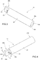
- the dispensing wand 10 in the example shown comprises a body 20 of elongate shape, for example made of food-grade plastic, having a cylindrical general form.
- the body 20 has an end 20a, the end surface or side of which has, formed therein, the inlet openings 10a and 10b connected to the outlets of the valves 7 and 8 in accordance with the diagrams shown in Figures 1 and 2 .
- the opposite end 20b of the body 20 in the example of embodiment shown forms a stepped recess defined by two surfaces or sides 20a and 20d which are essentially orthogonal to each other.
- the surface 20a is essentially parallel to the longitudinal direction of the body 20, while the surface 20c is essentially transverse to this direction.
- the end 20b also has a further end surface or side 20e, which is essentially transverse and relative to which the surface 20c is axially set back, towards the end 20a of the body 20.
- the conduit 21 extends between the inlet opening 10a and an outlet opening 10c, which is formed in the surface 20c of the body 20 and has an associated ejection nozzle 23 intended during use to emit a flow or jet of steam in a direction essentially parallel to the longitudinal axis of the body 20.
- the conduit 22 extends from the inlet opening 10b ( Figure 6 ) to a certain distance from the end surface or side 20e of the body 20 and is connected to a transverse outlet passage 10d which emerges in the surface or side 20d and inside which an ejector nozzle 24 is mounted.
- the arrangement is such that, during use, when the distal end of the dispensing wand 10 is immersed in the milk R, the flows of vapour and compressed air exiting from the nozzles 23 and 24 intersect each other. Owing to this characteristic feature, the steam bubbles formed in the milk M are effectively broken up into smaller-size bubbles owing to the effect of the compressed air emitted through the nozzle 24.
- receptacles R For use in relatively larger size receptacles R, such as large cups or jugs, it is also possible to use a configuration in which the functions of the nozzles 23 and 24 are exchanged, namely where the steam is emitted through the transverse nozzle 24, while the compressed air is emitted through the longitudinal nozzle 23.
- the wand 10 is preferably provided with an electric temperature sensor, such as that indicated by 25 in the drawings.
- this temperature sensor is mounted on the end surface or side 20e of the wand, so as to be operationally immersed within the milk M to be frothed and so as to heat the inside of the receptacle R.
- the device 1 comprises an electronic unit, denoted by ECU in Figures 1 and 2 .
- the unit ECU has a plurality of inlets which are connected to the flow meter 5 and the temperature sensors 6 and 25.
- This unit ECU also comprises a plurality of outlets connected to the electric vibration pump 2, the heating device 4 and the electric valves 7 and 9 and the motor 11 associated with the air compressor 9.
- a setting and command device 30 is also connected to the unit ECU and may be used by the user to perform operation of the device 1 selectively in a plurality of different modes as regards both the temperature and degree of frothing of the milk which are required.
- the user immerses the dispensing wand 10 in the milk, so that the nozzles 23 and 24 and the temperature sensor 25 are submerged and located near the bottom of the receptacle R.
- the user by means of the setting device 30 performs activation of the heating and frothing device 1 in the desired mode.
- the control unit ECU correspondingly activates the electric pump 2, the heating device 4 and the motor 11 of the compressor 9 and also switches the electric valve 7 to the condition where it connects the outlet of the heating device 4 to the inlet 10a of the dispensing wand 10.
- the wand 10 therefore receives both a flow of steam at the inlet 10a and (via the electric valve 8) a flow of compressed air at the inlet 10b.
- the nozzles 23 and 24 of the wand 10 therefore emit, into the milk M contained in the receptacle R, respective intersecting flows of steam and compressed air which are therefore mixed outside the device 1 as a whole, within the milk to be frothed.
- the unit ECU receives the signals provided by the flow meter 5 and by the temperature sensors 6 and 25. Depending on the signals provided by these sensors and depending on the operating mode set by the user via the command device 30, the unit ECU may modulate the flowrate of the electric pump 2, the level of heating performed in the heating device 4 and the flowrate of compressed air supplied by the compressor/motor 9, 11.
- the temperature sensor 25 it is possible to check when the desired temperature for the milk M is reached.
- the control unit ECU deactivates the electric pump 2, the heating device 4 and the motor 11 of the compressor and may conveniently activate an operating cycle for cleaning and sanitization of the conduits and the nozzles of the dispensing wand 10.
- the unit ECU activates the electric pump 2 and the heating device 4 in order to generate a flow of steam and sets the electric valves 7 and 8 to the condition where they connect the outlet of the heater 4 to the inlets 10a and 10b, respectively, of the dispensing wand 10.
- the conduits 21 and 22 and the associated nozzles 23 and 24 of the dispensing wand 10 are crossed, simultaneously, or alternately, by flows of high-temperature steam which clean them, preventing possible blockages, and sanitize them.
- the wand 10 is introduced into a small empty container, the high-temperature steam emerging from the nozzles 23 and 24 is able to perform also at least partial cleaning of the external surface of the wand.
- the unit ECU may be set so as to recognize the occurrence of such a situation and activate in this case the compressor/motor 9, 11 for a predetermined period of time, for example a few seconds, in order to prevent the milk from rising back up towards the electric valve 8.
- the unit ECU may recognize the condition where the wand is immersed in the hot milk by analyzing the signal provided by the temperature sensor 25: if, after preparation of hot/frothed milk, the temperature detected by the sensor 25 slowly decreases, the unit ECU assumes that the wand 10 is still immersed and activates the compressor/motor 9, 11.
- the unit ECU assumes that the wand is no longer immersed in the hot beverage and avoids activating the compressor/motor 9, 11.
Landscapes
- Engineering & Computer Science (AREA)
- Food Science & Technology (AREA)
- Life Sciences & Earth Sciences (AREA)
- Chemical & Material Sciences (AREA)
- Polymers & Plastics (AREA)
- Apparatus For Making Beverages (AREA)
Claims (13)
- Vorrichtung (1) zum Erhitzen und Aufschäumen von Milch (M) zur Verwendung bei der Zubereitung eines Heißgetränks wie Cappuccino und dergleichen, umfassend
ein Dampferzeugungsmittel (2, 4),
ein Drucklufterzeugungsmittel (9, 11) und
eine Abgabedüse (10), die mit der Dampferzeugungseinrichtung (2, 4) und der Drucklufterzeugungseinrichtung (9, 11) verbunden ist oder damit verbunden werden kann, und die dazu ausgerichtet ist, in einen Behälter (R), der die zu erhitzende und aufzuschäumende Milch (M) enthält, eingetaucht zu werden;
wobei die Abgabedüse (10) erste und zweite Leitungen (21, 22) definiert, die voneinander getrennt sind und jeweils separate Einlässe (10a, 10b) zur Verbindung mit der Dampferzeugungseinrichtung (2, 4) und der Drucklufterzeugungseinrichtung (9, 11) sowie entsprechende separate Auslässe (10c, 23; 10d, 24) zum Abgeben eines Dampfstromes bzw. eines Druckluftstromes innerhalb der in dem Behälter (R) enthaltenen Milch (M) während des Gebrauchs aufweisen;
wobei die Vorrichtung (1) dadurch gekennzeichnet ist, dass die Auslässe (23, 24) derart angeordnet sind, dass der daraus austretende Dampfstrom und Druckluftstrom einander schneiden. - Vorrichtung nach Anspruch 1, die weiterhin umfasst:einen mit der Abgabedüse (10) verknüpften Temperatursensor (25) zur Bereitstellung elektrischer Signale, welche die Temperatur der Milch (M) in dem Behälter (R) anzeigen, undeine Steuereinheit (ECU), die dazu ausgelegt ist, das Dampferzeugungsmittel (2, 4) und das Drucklufterzeugungsmittel (9, 11) in vorbestimmten Betriebsarten abhängig von den durch den Temperatursensor (25) bereitgestellten Signalen zu steuern und zu koordinieren;wobei das Dampferzeugungsmittel (2, 4) eine elektrische Vibrationspumpe (2) umfasst, deren Einlass mit einem Wassertank (3) verbunden ist und deren Auslass oder Abgabe mit einer Sofortheizvorrichtung (4) verbunden ist;wobei die Steuereinheit (ECU) dazu ausgelegt ist, die Strömungsrate der elektrischen Pumpe (21) in Abhängigkeit von den durch den Temperatursensor (25) bereitgestellten Signalen zu modulieren.
- Vorrichtung nach Anspruch 1 oder 2, die ein erstes elektrisches Ventil (7) umfasst, das zwischen dem Dampferzeugungsmittel (2, 4) und dem Abgabedüse (10) angeordnet ist, um einen Dampfstrom zu der Abgabedüse (10) wahlweise zuzulassen oder zu verhindern.
- Vorrichtung nach einem der vorangegangenen Ansprüche, die ein (weiteres) elektrisches Ventil (8) umfasst, das zwischen dem Drucklufterzeugungsmittel (9, 11) und der Abgabedüse (10) ausgerichtet ist.
- Vorrichtung nach Anspruch 3 und Anspruch 4, wobei das weitere elektrische Ventil (8) ebenfalls mit dem Auslass der Heizvorrichtung (4) verbunden ist und dazu ausgerichtet ist, wahlweise jeweils eine erste bzw. eine zweite Bedingung anzunehmen, in der es jeweils das Drucklufterzeugungsmittel (9, 11) bzw. die Heizeinrichtung (4) mit der Abgabedüse (410) verbindet, um die vorgenannte zweite Leitung (22) der Abgabedüse (10) jeweils mit Druckluft bzw. Dampf zu versorgen.
- Vorrichtung nach einem der vorangegangenen Ansprüche, die weiterhin einen Durchflussmesser (5) umfasst, der dazu ausgerichtet ist, der Steuereinheit (ECU) Signale bereitzustellen, die die Durchflussmenge des durch die elektrische Pumpe (2) strömenden Wassers anzeigen.
- Vorrichtung nach einem der vorangegangenen Ansprüche, wobei die Abgabedüse (10) eine längliche Form hat und die Leitungen (21, 22) sich entlang der Längsrichtung davon erstrecken; wobei die Auslässe (23, 24) der Leitungen (21, 22) derart angeordnet sind, dass ein Auslass (23) einen ersten Strom entlang der Längsrichtung abgibt und der andere Auslass (24) einen zweiten Strom entlang einer den ersten Fluss kreuzenden Richtung abgibt.
- Vorrichtung nach Anspruch 7, wobei der andere Auslass (24) der Abgabedüse (10) derart angeordnet ist, dass er einen Strom ausgeben kann, der im Wesentlichen orthogonal zu dem ersten Strom ist.
- Vorrichtung nach Anspruch 7 oder Anspruch 8, wobei die Abgabedüse (10) derart mit dem Dampferzeugungsmittel (2, 4) und dem Drucklufterzeugungsmittel (9, 11) verbunden ist, dass ihre Auslässe (23, 24) dazu ausgerichtet sind, einen Dampfstrom entlang der Längsrichtung und einen Druckluftstrom entlang einer den Dampfstrom kreuzenden Richtung abzugeben.
- Vorrichtung nach Anspruch 7 oder Anspruch 8, wobei die Abgabedüse (10) derart mit dem Dampferzeugungsmittel (2, 4) und dem Drucklufterzeugungsmittel (9, 11) verbunden ist, dass ihre Auslässe (23, 24) dazu ausgerichtet sind, einen Druckluftstrom entlang der Längsrichtung und einen Dampfstrom entlang einer den Druckluftstrom kreuzenden Richtung abzugeben.
- Abgabedüse (10) zur Verwendung bei einer Vorrichtung (1) nach wenigstens einem der vorangegangenen Ansprüche, umfassend einen Körper (20) mit einer länglichen Form, in dem erste und zweite Leitungen (21, 22) definiert sind, die voneinander getrennt sind und jeweils separate Einlässe (10a, 10b) zur Verbindung mit der Dampferzeugungseinrichtung (2, 4) und der Drucklufterzeugungseinrichtung (9, 11) aufweisen, sowie entsprechende separate Auslässe (23, 24) zum Abgeben eines Dampfstromes bzw. eines Druckluftstromes innerhalb der in dem Behälter (R) enthaltenen Milch (M) während des Gebrauchs; wobei die Auslässe (23, 24) derart angeordnet sind, dass der daraus austretende Dampfstrom und Druckluftstrom einander schneiden, wobei ein Auslass (24) der Abgabedüse (10) derart angeordnet ist, dass er einen Strom abgeben kann, der im Wesentlichen orthogonal zu dem Strom ist, der von dem anderen Auslass (23) abgegeben wird.
- Abgabedüse nach Anspruch 11, wobei sich die Leitungen (21, 22) entlang der Längsrichtung der Düse (10) erstrecken; und wobei die Auslässe (23, 24) der Leitungen (21, 22) derart angeordnet sind, dass ein Auslass (23) einen ersten Strom entlang der Längsrichtung abgibt und der andere Auslass (24) einen zweiten Strom entlang einer den ersten Fluss kreuzenden Richtung abgibt.
- Maschine zum Zubereiten von Heißgetränken, insbesondere Espressokaffee, mit einer Vorrichtung (1) zum Erhitzen und Aufschäumen von Milch (M) nach wenigstens einem der Ansprüche 1 bis 10.
Applications Claiming Priority (2)
| Application Number | Priority Date | Filing Date | Title |
|---|---|---|---|
| ITTO20141063 | 2014-12-18 | ||
| PCT/IB2015/059402 WO2016097923A1 (en) | 2014-12-18 | 2015-12-07 | Device for heating and frothing milk and wand for such a device |
Publications (2)
| Publication Number | Publication Date |
|---|---|
| EP3232878A1 EP3232878A1 (de) | 2017-10-25 |
| EP3232878B1 true EP3232878B1 (de) | 2019-03-06 |
Family
ID=52472444
Family Applications (1)
| Application Number | Title | Priority Date | Filing Date |
|---|---|---|---|
| EP15818054.7A Active EP3232878B1 (de) | 2014-12-18 | 2015-12-07 | Vorrichtung zum erwärmen und aufschäumen von milch und stab für solch eine vorrichtung |
Country Status (5)
| Country | Link |
|---|---|
| US (1) | US11122928B2 (de) |
| EP (1) | EP3232878B1 (de) |
| CN (1) | CN106998951B (de) |
| AU (1) | AU2015365471B2 (de) |
| WO (1) | WO2016097923A1 (de) |
Families Citing this family (18)
| Publication number | Priority date | Publication date | Assignee | Title |
|---|---|---|---|---|
| CH710913B1 (de) * | 2015-03-26 | 2020-03-31 | Steiner Ag Weggis | Verfahren und Dampflanze zum Erzeugen von Milchschaum. |
| IT201600080088A1 (it) * | 2016-07-29 | 2018-01-29 | Lavazza Luigi Spa | Macchina per la preparazione di bevande, in particolare caffe' espresso, valvola e gruppo valvolare utilizzabile in tale macchina |
| MX2019009740A (es) * | 2017-02-15 | 2020-01-27 | 2266170 Ontario Inc | Sistema de infusion y preparacion de bebidas. |
| WO2018226623A1 (en) * | 2017-06-05 | 2018-12-13 | Keurig Green Mountain, Inc. | Vent orifice and filter for beverage machine |
| US11083328B2 (en) | 2017-06-22 | 2021-08-10 | Starbucks Corporation | Apparatus and method for foaming a beverage |
| IT201800001717A1 (it) * | 2018-01-24 | 2019-07-24 | De Longhi Appliances Srl | Dispositivo per il riscaldamento e l’emulsione di bevande |
| IT201800003932A1 (it) * | 2018-03-26 | 2019-09-26 | Rancilio Group Spa | Metodo per il controllo della temperatura del latte in un dispositivo per scaldare e/o schiumare il latte |
| US11058250B2 (en) | 2018-09-06 | 2021-07-13 | Starbucks Corporation | Apparatus for foaming a beverage |
| IT201900009240A1 (it) * | 2019-06-17 | 2020-12-17 | Gruppo Cimbali Spa | Lancia di erogazione per un apparato di montatura del latte ed apparato per la montatura del latte con tale lancia |
| IT201900009249A1 (it) * | 2019-06-17 | 2020-12-17 | Gruppo Cimbali Spa | Apparato per la montatura del latte e metodo per la montatura del latte mediante tale apparato |
| IT201900012693A1 (it) * | 2019-07-23 | 2021-01-23 | Cma Macch Per Caffe Srl | Dispositivo e procedimento per la preparazione di latte schiumato |
| WO2021055556A1 (en) * | 2019-09-20 | 2021-03-25 | Keurig Green Mountain, Inc. | Method and apparatus for beverage frothing |
| DE102022103537B4 (de) * | 2022-02-15 | 2025-11-06 | Next Level Coffee GmbH | Dampflanze für eine Kaffeemaschine |
| WO2025021630A1 (de) | 2023-07-27 | 2025-01-30 | Melitta Professional Coffee Solutions GmbH & Co. KG | Vorrichtung und verfahren zum erzeugen von milch-luft-emulsionen |
| DE102024105055A1 (de) | 2023-07-27 | 2025-01-30 | Melitta Professional Coffee Solutions GmbH & Co. KG | Vorrichtung und Verfahren zum Erzeugen von Milch-Luft-Emulsionen |
| WO2025155326A1 (en) | 2024-01-18 | 2025-07-24 | Sharkninja Operating Llc | Preparation of beverage machines for cold beverage brewing |
| US12369741B1 (en) | 2024-01-18 | 2025-07-29 | Sharkninja Operating Llc | Preventing coffee bean grinder jamming |
| US12575692B2 (en) | 2024-01-18 | 2026-03-17 | Sharkninja Operating Llc | Suggesting coffee bean grind size for beverage machines |
Family Cites Families (14)
| Publication number | Priority date | Publication date | Assignee | Title |
|---|---|---|---|---|
| CH673212A5 (de) * | 1986-09-24 | 1990-02-28 | Krups Stiftung | |
| DE3842206C2 (de) * | 1988-12-15 | 1994-05-26 | Krups Fa Robert | Vorrichtung zum Zubereiten von Cappuccino |
| DE8816009U1 (de) * | 1988-12-23 | 1990-04-19 | Bosch-Siemens Hausgeräte GmbH, 8000 München | Gerät zum Aufheizen oder Aufschäumen von Getränken, insbesondere im Haushalt |
| DE4220986A1 (de) | 1992-06-26 | 1994-01-05 | Gotthard Dipl Ing Mahlich | Vorrichtung zum Zubereiten von Milchschaum für Cappuccino |
| US6203837B1 (en) * | 1998-10-06 | 2001-03-20 | Xcafe' Llc | Coffee system |
| WO2003092458A1 (en) | 2002-05-06 | 2003-11-13 | Cimbali, S.P.A. | Device for heating and working up milk |
| ITTO20030271A1 (it) * | 2003-04-09 | 2004-10-10 | Rancilio Macchine Caffe | Dispositivo erogatore automatico di vapore per la preparazione di bevande calde e/o schiumate. |
| ATE404094T1 (de) * | 2004-12-21 | 2008-08-15 | Inventum Holding B V | Vorrichtung zur zubereitung eines getränks |
| ES2324844T3 (es) * | 2007-01-23 | 2009-08-17 | Rancilio Macchine Per Caffe' S.P.A. | Dispositivo para calentar y/o espumar una bebida. |
| DE102009025986A1 (de) * | 2009-06-17 | 2011-03-31 | Cafina Ag | Einrichtung zum Erwärmen und Aufschäumen von Milch |
| JP5661759B2 (ja) * | 2010-06-03 | 2015-01-28 | パナソニックIpマネジメント株式会社 | コーヒーメーカー |
| BR112013000212A8 (pt) * | 2010-07-08 | 2016-09-06 | Koninklijke Philips Eletronics N V | "sistema de formação de espuma de leite e máquina de café" |
| ITMI20131726A1 (it) * | 2013-10-17 | 2015-04-18 | Swiss Caffe Asia Ltd | Macchina automatica per la preparazione di bevande, quali caffe' espresso, cappuccino e simili. |
| DE102014108415B3 (de) * | 2014-06-16 | 2015-11-19 | Eugster/Frismag Ag | Getränkezubereitungsvorrichtung sowie Betriebsverfahren |
-
2015
- 2015-12-07 EP EP15818054.7A patent/EP3232878B1/de active Active
- 2015-12-07 WO PCT/IB2015/059402 patent/WO2016097923A1/en not_active Ceased
- 2015-12-07 US US15/534,272 patent/US11122928B2/en active Active
- 2015-12-07 AU AU2015365471A patent/AU2015365471B2/en active Active
- 2015-12-07 CN CN201580068611.2A patent/CN106998951B/zh active Active
Non-Patent Citations (1)
| Title |
|---|
| None * |
Also Published As
| Publication number | Publication date |
|---|---|
| EP3232878A1 (de) | 2017-10-25 |
| US11122928B2 (en) | 2021-09-21 |
| CN106998951B (zh) | 2021-01-26 |
| AU2015365471B2 (en) | 2020-02-27 |
| AU2015365471A1 (en) | 2017-07-27 |
| WO2016097923A1 (en) | 2016-06-23 |
| CN106998951A (zh) | 2017-08-01 |
| US20180353001A1 (en) | 2018-12-13 |
Similar Documents
| Publication | Publication Date | Title |
|---|---|---|
| EP3232878B1 (de) | Vorrichtung zum erwärmen und aufschäumen von milch und stab für solch eine vorrichtung | |
| US9038529B2 (en) | Coffee machine comprising a frothing device and means for cleaning the frothing device and a milk suction line and process for rinsing the milk suction line | |
| US9788686B2 (en) | Electrically operated drink maker, in particular electrically operated coffee machine, with steam lance for frothing up milk | |
| JP6095695B2 (ja) | 膨張チャンバを有する液体供給タンク | |
| EP3313245B1 (de) | Verfahren zur herstellung von aufgeschäumter milch | |
| JP5503715B2 (ja) | 飲料生成機のドレン | |
| US8337635B2 (en) | Beverage preparation device with in-line scale removal system and descaling method using such system | |
| US9060646B2 (en) | Milk frothing with pressurized gas | |
| EP2299881B1 (de) | Vorrichtung zum quirlen von milch und verfahren zum reinigen einer solchen vorrichtung | |
| US20130040028A1 (en) | Circulatory milk frothing device | |
| CN102740749A (zh) | 带有安全清洁装置的饮料分配器 | |
| CN106998953A (zh) | 用于制备饮料,尤其是浓缩咖啡的机器 | |
| WO2018226633A1 (en) | Pressure relief valve configuration for beverage machine | |
| US20220313004A1 (en) | Method and apparatus for beverage frothing | |
| EP3697270B1 (de) | Getränkeverkaufsautomat | |
| CA3065342A1 (en) | Vent orifice and filter for beverage machine | |
| EP3771371B1 (de) | Kaffeemaschinenablaufrinne | |
| HK1261442A1 (en) | Milk frothing system and method of operation | |
| HK1261442B (en) | Milk frothing system and method of operation | |
| HK1208605A1 (en) | Coffee machine and method for cleaning water tank of coffee machine | |
| HK1208605B (en) | Coffee machine and method for cleaning water tank of coffee machine |
Legal Events
| Date | Code | Title | Description |
|---|---|---|---|
| STAA | Information on the status of an ep patent application or granted ep patent |
Free format text: STATUS: THE INTERNATIONAL PUBLICATION HAS BEEN MADE |
|
| PUAI | Public reference made under article 153(3) epc to a published international application that has entered the european phase |
Free format text: ORIGINAL CODE: 0009012 |
|
| STAA | Information on the status of an ep patent application or granted ep patent |
Free format text: STATUS: REQUEST FOR EXAMINATION WAS MADE |
|
| 17P | Request for examination filed |
Effective date: 20170523 |
|
| AK | Designated contracting states |
Kind code of ref document: A1 Designated state(s): AL AT BE BG CH CY CZ DE DK EE ES FI FR GB GR HR HU IE IS IT LI LT LU LV MC MK MT NL NO PL PT RO RS SE SI SK SM TR |
|
| AX | Request for extension of the european patent |
Extension state: BA ME |
|
| DAV | Request for validation of the european patent (deleted) | ||
| DAX | Request for extension of the european patent (deleted) | ||
| GRAP | Despatch of communication of intention to grant a patent |
Free format text: ORIGINAL CODE: EPIDOSNIGR1 |
|
| STAA | Information on the status of an ep patent application or granted ep patent |
Free format text: STATUS: GRANT OF PATENT IS INTENDED |
|
| INTG | Intention to grant announced |
Effective date: 20180920 |
|
| GRAS | Grant fee paid |
Free format text: ORIGINAL CODE: EPIDOSNIGR3 |
|
| GRAA | (expected) grant |
Free format text: ORIGINAL CODE: 0009210 |
|
| STAA | Information on the status of an ep patent application or granted ep patent |
Free format text: STATUS: THE PATENT HAS BEEN GRANTED |
|
| AK | Designated contracting states |
Kind code of ref document: B1 Designated state(s): AL AT BE BG CH CY CZ DE DK EE ES FI FR GB GR HR HU IE IS IT LI LT LU LV MC MK MT NL NO PL PT RO RS SE SI SK SM TR |
|
| REG | Reference to a national code |
Ref country code: GB Ref legal event code: FG4D |
|
| REG | Reference to a national code |
Ref country code: CH Ref legal event code: EP Ref country code: AT Ref legal event code: REF Ref document number: 1103429 Country of ref document: AT Kind code of ref document: T Effective date: 20190315 |
|
| REG | Reference to a national code |
Ref country code: DE Ref legal event code: R096 Ref document number: 602015026041 Country of ref document: DE |
|
| REG | Reference to a national code |
Ref country code: IE Ref legal event code: FG4D |
|
| REG | Reference to a national code |
Ref country code: NL Ref legal event code: MP Effective date: 20190306 |
|
| REG | Reference to a national code |
Ref country code: LT Ref legal event code: MG4D |
|
| PG25 | Lapsed in a contracting state [announced via postgrant information from national office to epo] |
Ref country code: SE Free format text: LAPSE BECAUSE OF FAILURE TO SUBMIT A TRANSLATION OF THE DESCRIPTION OR TO PAY THE FEE WITHIN THE PRESCRIBED TIME-LIMIT Effective date: 20190306 Ref country code: NO Free format text: LAPSE BECAUSE OF FAILURE TO SUBMIT A TRANSLATION OF THE DESCRIPTION OR TO PAY THE FEE WITHIN THE PRESCRIBED TIME-LIMIT Effective date: 20190606 Ref country code: FI Free format text: LAPSE BECAUSE OF FAILURE TO SUBMIT A TRANSLATION OF THE DESCRIPTION OR TO PAY THE FEE WITHIN THE PRESCRIBED TIME-LIMIT Effective date: 20190306 Ref country code: LT Free format text: LAPSE BECAUSE OF FAILURE TO SUBMIT A TRANSLATION OF THE DESCRIPTION OR TO PAY THE FEE WITHIN THE PRESCRIBED TIME-LIMIT Effective date: 20190306 |
|
| PG25 | Lapsed in a contracting state [announced via postgrant information from national office to epo] |
Ref country code: NL Free format text: LAPSE BECAUSE OF FAILURE TO SUBMIT A TRANSLATION OF THE DESCRIPTION OR TO PAY THE FEE WITHIN THE PRESCRIBED TIME-LIMIT Effective date: 20190306 Ref country code: HR Free format text: LAPSE BECAUSE OF FAILURE TO SUBMIT A TRANSLATION OF THE DESCRIPTION OR TO PAY THE FEE WITHIN THE PRESCRIBED TIME-LIMIT Effective date: 20190306 Ref country code: RS Free format text: LAPSE BECAUSE OF FAILURE TO SUBMIT A TRANSLATION OF THE DESCRIPTION OR TO PAY THE FEE WITHIN THE PRESCRIBED TIME-LIMIT Effective date: 20190306 Ref country code: GR Free format text: LAPSE BECAUSE OF FAILURE TO SUBMIT A TRANSLATION OF THE DESCRIPTION OR TO PAY THE FEE WITHIN THE PRESCRIBED TIME-LIMIT Effective date: 20190607 Ref country code: BG Free format text: LAPSE BECAUSE OF FAILURE TO SUBMIT A TRANSLATION OF THE DESCRIPTION OR TO PAY THE FEE WITHIN THE PRESCRIBED TIME-LIMIT Effective date: 20190606 Ref country code: LV Free format text: LAPSE BECAUSE OF FAILURE TO SUBMIT A TRANSLATION OF THE DESCRIPTION OR TO PAY THE FEE WITHIN THE PRESCRIBED TIME-LIMIT Effective date: 20190306 |
|
| REG | Reference to a national code |
Ref country code: AT Ref legal event code: MK05 Ref document number: 1103429 Country of ref document: AT Kind code of ref document: T Effective date: 20190306 |
|
| PG25 | Lapsed in a contracting state [announced via postgrant information from national office to epo] |
Ref country code: ES Free format text: LAPSE BECAUSE OF FAILURE TO SUBMIT A TRANSLATION OF THE DESCRIPTION OR TO PAY THE FEE WITHIN THE PRESCRIBED TIME-LIMIT Effective date: 20190306 Ref country code: PT Free format text: LAPSE BECAUSE OF FAILURE TO SUBMIT A TRANSLATION OF THE DESCRIPTION OR TO PAY THE FEE WITHIN THE PRESCRIBED TIME-LIMIT Effective date: 20190706 Ref country code: AL Free format text: LAPSE BECAUSE OF FAILURE TO SUBMIT A TRANSLATION OF THE DESCRIPTION OR TO PAY THE FEE WITHIN THE PRESCRIBED TIME-LIMIT Effective date: 20190306 Ref country code: CZ Free format text: LAPSE BECAUSE OF FAILURE TO SUBMIT A TRANSLATION OF THE DESCRIPTION OR TO PAY THE FEE WITHIN THE PRESCRIBED TIME-LIMIT Effective date: 20190306 Ref country code: RO Free format text: LAPSE BECAUSE OF FAILURE TO SUBMIT A TRANSLATION OF THE DESCRIPTION OR TO PAY THE FEE WITHIN THE PRESCRIBED TIME-LIMIT Effective date: 20190306 Ref country code: EE Free format text: LAPSE BECAUSE OF FAILURE TO SUBMIT A TRANSLATION OF THE DESCRIPTION OR TO PAY THE FEE WITHIN THE PRESCRIBED TIME-LIMIT Effective date: 20190306 Ref country code: SK Free format text: LAPSE BECAUSE OF FAILURE TO SUBMIT A TRANSLATION OF THE DESCRIPTION OR TO PAY THE FEE WITHIN THE PRESCRIBED TIME-LIMIT Effective date: 20190306 |
|
| PG25 | Lapsed in a contracting state [announced via postgrant information from national office to epo] |
Ref country code: PL Free format text: LAPSE BECAUSE OF FAILURE TO SUBMIT A TRANSLATION OF THE DESCRIPTION OR TO PAY THE FEE WITHIN THE PRESCRIBED TIME-LIMIT Effective date: 20190306 Ref country code: SM Free format text: LAPSE BECAUSE OF FAILURE TO SUBMIT A TRANSLATION OF THE DESCRIPTION OR TO PAY THE FEE WITHIN THE PRESCRIBED TIME-LIMIT Effective date: 20190306 |
|
| REG | Reference to a national code |
Ref country code: DE Ref legal event code: R097 Ref document number: 602015026041 Country of ref document: DE |
|
| PG25 | Lapsed in a contracting state [announced via postgrant information from national office to epo] |
Ref country code: IS Free format text: LAPSE BECAUSE OF FAILURE TO SUBMIT A TRANSLATION OF THE DESCRIPTION OR TO PAY THE FEE WITHIN THE PRESCRIBED TIME-LIMIT Effective date: 20190706 Ref country code: AT Free format text: LAPSE BECAUSE OF FAILURE TO SUBMIT A TRANSLATION OF THE DESCRIPTION OR TO PAY THE FEE WITHIN THE PRESCRIBED TIME-LIMIT Effective date: 20190306 |
|
| PLBE | No opposition filed within time limit |
Free format text: ORIGINAL CODE: 0009261 |
|
| STAA | Information on the status of an ep patent application or granted ep patent |
Free format text: STATUS: NO OPPOSITION FILED WITHIN TIME LIMIT |
|
| PG25 | Lapsed in a contracting state [announced via postgrant information from national office to epo] |
Ref country code: DK Free format text: LAPSE BECAUSE OF FAILURE TO SUBMIT A TRANSLATION OF THE DESCRIPTION OR TO PAY THE FEE WITHIN THE PRESCRIBED TIME-LIMIT Effective date: 20190306 |
|
| 26N | No opposition filed |
Effective date: 20191209 |
|
| PG25 | Lapsed in a contracting state [announced via postgrant information from national office to epo] |
Ref country code: SI Free format text: LAPSE BECAUSE OF FAILURE TO SUBMIT A TRANSLATION OF THE DESCRIPTION OR TO PAY THE FEE WITHIN THE PRESCRIBED TIME-LIMIT Effective date: 20190306 |
|
| PG25 | Lapsed in a contracting state [announced via postgrant information from national office to epo] |
Ref country code: TR Free format text: LAPSE BECAUSE OF FAILURE TO SUBMIT A TRANSLATION OF THE DESCRIPTION OR TO PAY THE FEE WITHIN THE PRESCRIBED TIME-LIMIT Effective date: 20190306 |
|
| REG | Reference to a national code |
Ref country code: CH Ref legal event code: PL |
|
| REG | Reference to a national code |
Ref country code: BE Ref legal event code: MM Effective date: 20191231 |
|
| PG25 | Lapsed in a contracting state [announced via postgrant information from national office to epo] |
Ref country code: MC Free format text: LAPSE BECAUSE OF FAILURE TO SUBMIT A TRANSLATION OF THE DESCRIPTION OR TO PAY THE FEE WITHIN THE PRESCRIBED TIME-LIMIT Effective date: 20190306 |
|
| PG25 | Lapsed in a contracting state [announced via postgrant information from national office to epo] |
Ref country code: LU Free format text: LAPSE BECAUSE OF NON-PAYMENT OF DUE FEES Effective date: 20191207 Ref country code: IE Free format text: LAPSE BECAUSE OF NON-PAYMENT OF DUE FEES Effective date: 20191207 |
|
| PG25 | Lapsed in a contracting state [announced via postgrant information from national office to epo] |
Ref country code: CH Free format text: LAPSE BECAUSE OF NON-PAYMENT OF DUE FEES Effective date: 20191231 Ref country code: LI Free format text: LAPSE BECAUSE OF NON-PAYMENT OF DUE FEES Effective date: 20191231 Ref country code: BE Free format text: LAPSE BECAUSE OF NON-PAYMENT OF DUE FEES Effective date: 20191231 |
|
| PG25 | Lapsed in a contracting state [announced via postgrant information from national office to epo] |
Ref country code: CY Free format text: LAPSE BECAUSE OF FAILURE TO SUBMIT A TRANSLATION OF THE DESCRIPTION OR TO PAY THE FEE WITHIN THE PRESCRIBED TIME-LIMIT Effective date: 20190306 |
|
| PG25 | Lapsed in a contracting state [announced via postgrant information from national office to epo] |
Ref country code: HU Free format text: LAPSE BECAUSE OF FAILURE TO SUBMIT A TRANSLATION OF THE DESCRIPTION OR TO PAY THE FEE WITHIN THE PRESCRIBED TIME-LIMIT; INVALID AB INITIO Effective date: 20151207 Ref country code: MT Free format text: LAPSE BECAUSE OF FAILURE TO SUBMIT A TRANSLATION OF THE DESCRIPTION OR TO PAY THE FEE WITHIN THE PRESCRIBED TIME-LIMIT Effective date: 20190306 |
|
| PG25 | Lapsed in a contracting state [announced via postgrant information from national office to epo] |
Ref country code: MK Free format text: LAPSE BECAUSE OF FAILURE TO SUBMIT A TRANSLATION OF THE DESCRIPTION OR TO PAY THE FEE WITHIN THE PRESCRIBED TIME-LIMIT Effective date: 20190306 |
|
| P01 | Opt-out of the competence of the unified patent court (upc) registered |
Effective date: 20230601 |
|
| PGFP | Annual fee paid to national office [announced via postgrant information from national office to epo] |
Ref country code: GB Payment date: 20251218 Year of fee payment: 11 |
|
| PGFP | Annual fee paid to national office [announced via postgrant information from national office to epo] |
Ref country code: FR Payment date: 20251217 Year of fee payment: 11 |
|
| PGFP | Annual fee paid to national office [announced via postgrant information from national office to epo] |
Ref country code: DE Payment date: 20251222 Year of fee payment: 11 |
|
| PGFP | Annual fee paid to national office [announced via postgrant information from national office to epo] |
Ref country code: IT Payment date: 20251231 Year of fee payment: 11 |