EP3233869B1 - Vorrichtung und durchflussverfahren zur herstellung von borsäurederivaten - Google Patents
Vorrichtung und durchflussverfahren zur herstellung von borsäurederivaten Download PDFInfo
- Publication number
- EP3233869B1 EP3233869B1 EP15870720.8A EP15870720A EP3233869B1 EP 3233869 B1 EP3233869 B1 EP 3233869B1 EP 15870720 A EP15870720 A EP 15870720A EP 3233869 B1 EP3233869 B1 EP 3233869B1
- Authority
- EP
- European Patent Office
- Prior art keywords
- continuous flow
- optionally substituted
- alkyl
- compound
- formula
- Prior art date
- Legal status (The legal status is an assumption and is not a legal conclusion. Google has not performed a legal analysis and makes no representation as to the accuracy of the status listed.)
- Active
Links
- 0 C[C@@](B1O[C@@](C)([C@@](C2)C(C)(C)[C@@]2C2)[C@]2O1)*N[C@@](*)CC(O*)=O Chemical compound C[C@@](B1O[C@@](C)([C@@](C2)C(C)(C)[C@@]2C2)[C@]2O1)*N[C@@](*)CC(O*)=O 0.000 description 4
Images



Classifications
-
- C—CHEMISTRY; METALLURGY
- C07—ORGANIC CHEMISTRY
- C07F—ACYCLIC, CARBOCYCLIC OR HETEROCYCLIC COMPOUNDS CONTAINING ELEMENTS OTHER THAN CARBON, HYDROGEN, HALOGEN, OXYGEN, NITROGEN, SULFUR, SELENIUM OR TELLURIUM
- C07F5/00—Compounds containing elements of Groups 3 or 13 of the Periodic Table
- C07F5/02—Boron compounds
- C07F5/025—Boronic and borinic acid compounds
-
- C—CHEMISTRY; METALLURGY
- C07—ORGANIC CHEMISTRY
- C07C—ACYCLIC OR CARBOCYCLIC COMPOUNDS
- C07C19/00—Acyclic saturated compounds containing halogen atoms
- C07C19/01—Acyclic saturated compounds containing halogen atoms containing chlorine
- C07C19/03—Chloromethanes
-
- C—CHEMISTRY; METALLURGY
- C07—ORGANIC CHEMISTRY
- C07D—HETEROCYCLIC COMPOUNDS
- C07D307/00—Heterocyclic compounds containing five-membered rings having one oxygen atom as the only ring hetero atom
- C07D307/02—Heterocyclic compounds containing five-membered rings having one oxygen atom as the only ring hetero atom not condensed with other rings
- C07D307/04—Heterocyclic compounds containing five-membered rings having one oxygen atom as the only ring hetero atom not condensed with other rings having no double bonds between ring members or between ring members and non-ring members
- C07D307/06—Heterocyclic compounds containing five-membered rings having one oxygen atom as the only ring hetero atom not condensed with other rings having no double bonds between ring members or between ring members and non-ring members with only hydrogen atoms or radicals containing only hydrogen and carbon atoms, directly attached to ring carbon atoms
-
- C—CHEMISTRY; METALLURGY
- C07—ORGANIC CHEMISTRY
- C07F—ACYCLIC, CARBOCYCLIC OR HETEROCYCLIC COMPOUNDS CONTAINING ELEMENTS OTHER THAN CARBON, HYDROGEN, HALOGEN, OXYGEN, NITROGEN, SULFUR, SELENIUM OR TELLURIUM
- C07F1/00—Compounds containing elements of Groups 1 or 11 of the Periodic Table
- C07F1/02—Lithium compounds
Definitions
- the present disclosure relates to a continuous flow process for production of boronic acid derivatives and apparatus of performing the same. More particularly, it relates to a continuous flow process for a large scale production of boronic acid derivatives.
- Boronic acid derivatives are useful as potentiators of antimicrobial compounds.
- Some methods for boronic ester synthesis include the homologation of boronic esters by addition of a dichloroalkyllithium reagent, forming an intermediate boronate complex in the presence of a Lewis acid catalyst.
- the Lewis acid promotes the rearrangement reaction and minimizes epimerization at the alpha-carbon atom.
- maintenance of very low temperature ( ⁇ -90 °C), exclusion of water and careful control of Lewis acid stoichiometry are required for good results.
- WO2013033461 (A1 ) describes heterocyclic boronic acid ester derivatives and therapeutic uses thereof.
- US2014194384 (A1 ) describes boronic acid derivatives and therapeutic uses thereof.
- Some embodiments disclosed herein include a process for production of a compound of Formula (Ia) or (Ib), wherein:
- Some embodiments disclosed herein include an apparatus for production of a compound of Formula Ia or Ib, wherein:
- the disclosed technology relates to a continuous flow process for the production of boronic acid derivatives.
- the process allows the production of boronic acid derivatives such as the compound described herein with a high yield and high selectivity.
- the process operates under cryogenic conditions; however, reaction temperatures below -90 °C used for batch production can be avoided. In some embodiments, temperatures of -80 °C to -65 °C can be used to provide a more readily scalable process with better reproducibility and higher yield.
- This continuous flow process can be used in large scale production.
- the chiral boronic ester compound A is an intermediate in the synthesis of Compound B, a ⁇ -lactamase inhibitor.
- a continuous process In a continuous process, separate continuous flow conduits are used for each step of the reaction, and the reaction mixture flows from one operation to the next within the production line.
- the operations are performed continuously and some of the reaction parameters such as flow rate, molar ratio, and reaction temperatures can be easily and quickly adjusted based on a concurrent monitoring of the reaction product. Consequently, a continuous production process requires much smaller equipment volumes for achieving the same production capacity.
- a continuous operation helps to ensure the quality of the product.
- a continuous flow process may be preferable over a traditional batch process as it would mitigate the risks that are associated with potentially hazardous decomposition reactions of the lithium salt of dichloromethane.
- the shorter residence times in continuous flow set-up can allow operation at higher temperatures.
- a continuous flow process and the apparatus for performing the continuous flow process are often complicated to design and highly specific to the types of reaction product and production rate.
- the continuous flow process described herein by utilizing a continuous flow process to produce a reaction intermediate and performing the last quenching step in a non-continuous-flow vessel, has shown great reproducibility and high yield as compared to the other types continuous flow processes that involve performing the last quenching step inside a continuous flow conduit. Additionally, the continuous flow process described herein has allowed successful production of compound of formula I, particularly compound A, in a scale of over 880 kg with an average yield of over 90%.
- substantially free of water means a product has been dried using standard techniques known in the art and the product contains less than 0.5 % of water. In some embodiments, “substantially free of water” means the product contains less than 0.1% of water or no water.
- continuous flow conduit refers to any pipe, tube, channel, channeled plate, or any other vessel of suitable shape for conveying fluids in a continuous flow process.
- reaction time refers to the time required for the reaction mixture or stock solution to flow from the input to the output of a continuous flow conduit.
- thermally coupled refers to a direct or indirect coupling between two objects in way that facilitates heat transfer between the two objects.
- the vessel or continuous flow conduit can be immersed in the cooling bath to achieve a desired temperature.
- fluidly coupled means that a first component are in fluid communication with another component. Such fluid communication may be achieved by either direct or indirect connection via valves, pipes, conveyors, pumps, conduits and any other suitable connectors known by those skilled in the art.
- C a to C b “ or “C a-b “ in which "a” and “b” are integers refer to the number of carbon atoms in the specified group. That is, the group can contain from “a” to “b", inclusive, carbon atoms.
- a “C 1 to C 4 alkyl” or “C 1-4 alkyl” group refers to all alkyl groups having from 1 to 4 carbons, that is, CH 3 -, CH 3 CH 2 -, CH 3 CH 2 CH 2 -, (CH 3 ) 2 CH-, CH 3 CH 2 CH 2 CH 2 -, CH 3 CH 2 CH(CH 3 )- and (CH 3 ) 3 C-.
- halogen or "halo,” as used herein, means any one of the radio-stable atoms of column 7 of the Periodic Table of the Elements, e.g ., fluorine, chlorine, bromine, or iodine, with fluorine and chlorine being preferred.
- alkyl refers to a straight or branched hydrocarbon chain that is fully saturated (i.e., contains no double or triple bonds).
- the alkyl group may have 1 to 20 carbon atoms (whenever it appears herein, a numerical range such as “1 to 20" refers to each integer in the given range; e.g ., "1 to 20 carbon atoms” means that the alkyl group may consist of 1 carbon atom, 2 carbon atoms, 3 carbon atoms, etc. , up to and including 20 carbon atoms, although the present definition also covers the occurrence of the term "alkyl” where no numerical range is designated).
- the alkyl group may also be a medium size alkyl having 1 to 9 carbon atoms.
- the alkyl group could also be a lower alkyl having 1 to 4 carbon atoms.
- the alkyl group of the compounds may be designated as "C 1-4 alkyl” or similar designations.
- C 1-4 alkyl indicates that there are one to four carbon atoms in the alkyl chain, i.e., the alkyl chain is selected from the group consisting of methyl, ethyl, propyl, iso-propyl, n-butyl, iso-butyl, sec-butyl, and t-butyl.
- Typical alkyl groups include, but are in no way limited to, methyl, ethyl, propyl, isopropyl, butyl, isobutyl, tertiary butyl, pentyl, hexyl, and the like.
- alkoxy refers to the formula -OR wherein R is an alkyl as is defined above, such as “C 1-9 alkoxy”, including but not limited to methoxy, ethoxy, n-propoxy, 1-methylethoxy (isopropoxy), n-butoxy, iso-butoxy, sec-butoxy, and tert-butoxy, and the like.
- alkylthio refers to the formula -SR wherein R is an alkyl as is defined above, such as “C 1-9 alkylthio” and the like, including but not limited to methylmercapto, ethylmercapto, n-propylmercapto, 1-methylethylmercapto (isopropylmercapto), n-butylmercapto, iso-butylmercapto, sec-butylmercapto, tert-butylmercapto, and the like.
- alkenyl refers to a straight or branched hydrocarbon chain containing one or more double bonds.
- the alkenyl group may have 2 to 20 carbon atoms, although the present definition also covers the occurrence of the term "alkenyl” where no numerical range is designated.
- the alkenyl group may also be a medium size alkenyl having 2 to 9 carbon atoms.
- the alkenyl group could also be a lower alkenyl having 2 to 4 carbon atoms.
- the alkenyl group of the compounds may be designated as "C 2-4 alkenyl" or similar designations.
- C 2-4 alkenyl indicates that there are two to four carbon atoms in the alkenyl chain, i.e., the alkenyl chain is selected from the group consisting of ethenyl, propen-1-yl, propen-2-yl, propen-3-yl, buten-1-yl, buten-2-yl, buten-3-yl, buten-4-yl, 1-methyl-propen-1-yl, 2-methyl-propen-1-yl, 1-ethyl-ethen-1-yl, 2-methyl-propen-3-yl, buta-1,3-dienyl, buta-1,2,-dienyl, and buta-1,2-dien-4-yl.
- Typical alkenyl groups include, but are in no way limited to, ethenyl, propenyl, butenyl, pentenyl, and hexenyl, and the like.
- alkynyl refers to a straight or branched hydrocarbon chain containing one or more triple bonds.
- the alkynyl group may have 2 to 20 carbon atoms, although the present definition also covers the occurrence of the term "alkynyl” where no numerical range is designated.
- the alkynyl group may also be a medium size alkynyl having 2 to 9 carbon atoms.
- the alkynyl group could also be a lower alkynyl having 2 to 4 carbon atoms.
- the alkynyl group of the compounds may be designated as "C 2-4 alkynyl" or similar designations.
- C 2-4 alkynyl indicates that there are two to four carbon atoms in the alkynyl chain, i.e., the alkynyl chain is selected from the group consisting of ethynyl, propyn-1-yl, propyn-2-yl, butyn-1-yl, butyn-3-yl, butyn-4-yl, and 2-butynyl.
- Typical alkynyl groups include, but are in no way limited to, ethynyl, propynyl, butynyl, pentynyl, and hexynyl, and the like.
- heteroalkyl refers to a straight or branched hydrocarbon chain containing one or more heteroatoms, that is, an element other than carbon, including but not limited to, nitrogen, oxygen and sulfur, in the chain backbone.
- the heteroalkyl group may have 1 to 20 carbon atoms although the present definition also covers the occurrence of the term "heteroalkyl” where no numerical range is designated.
- the heteroalkyl group may also be a medium size heteroalkyl having 1 to 9 carbon atoms.
- the heteroalkyl group could also be a lower heteroalkyl having 1 to 4 carbon atoms.
- the heteroalkyl group of the compounds may be designated as "C 1-4 heteroalkyl" or similar designations.
- the heteroalkyl group may contain one or more heteroatoms.
- C 1-4 heteroalkyl indicates that there are one to four carbon atoms in the heteroalkyl chain and additionally one or more heteroatoms in the backbone of the chain.
- aromatic refers to a ring or ring system having a conjugated pi electron system and includes both carbocyclic aromatic (e.g., phenyl) and heterocyclic aromatic groups (e.g., pyridine).
- carbocyclic aromatic e.g., phenyl
- heterocyclic aromatic groups e.g., pyridine
- the term includes monocyclic or fused-ring polycyclic (i.e., rings which share adjacent pairs of atoms) groups provided that the entire ring system is aromatic.
- aryl refers to an aromatic ring or ring system (i.e., two or more fused rings that share two adjacent carbon atoms) containing only carbon in the ring backbone. When the aryl is a ring system, every ring in the system is aromatic.
- the aryl group may have 6 to 18 carbon atoms, although the present definition also covers the occurrence of the term "aryl” where no numerical range is designated. In some embodiments, the aryl group has 6 to 10 carbon atoms.
- the aryl group may be designated as "C 6-10 aryl,” “C 6 or C 10 aryl,” or similar designations. Examples of aryl groups include, but are not limited to, phenyl, naphthyl, azulenyl, and anthracenyl.
- aryloxy and arylthio refers to RO- and RS-, in which R is an aryl as is defined above, such as “C 6-10 aryloxy” or “C 6-10 arylthio” and the like, includingbut not limited to phenyloxy.
- an “aralkyl” or “arylalkyl” is an aryl group connected, as a substituent, via an alkylene group, such "C 7-14 aralkyl” and the like, including but not limited to benzyl, 2-phenylethyl, 3-phenylpropyl, and naphthylalkyl.
- the alkylene group is a lower alkylene group (i.e., a C 1-4 alkylene group).
- heteroaryl refers to an aromatic ring or ring system (i.e., two or more fused rings that share two adjacent atoms) that contain(s) one or more heteroatoms, that is, an element other than carbon, including but not limited to, nitrogen, oxygen and sulfur, in the ring backbone.
- heteroaryl is a ring system, every ring in the system is aromatic.
- the heteroaryl group may have 5-18 ring members (i.e., the number of atoms making up the ring backbone, including carbon atoms and heteroatoms), although the present definition also covers the occurrence of the term "heteroaryl" where no numerical range is designated.
- the heteroaryl group has 5 to 10 ring members or 5 to 7 ring members.
- the heteroaryl group may be designated as "5-7 membered heteroaryl,” "5-10 membered heteroaryl,” or similar designations.
- heteroaryl rings include, but are not limited to, furyl, thienyl, phthalazinyl, pyrrolyl, oxazolyl, thiazolyl, imidazolyl, pyrazolyl, isoxazolyl, isothiazolyl, triazolyl, thiadiazolyl, pyridinyl, pyridazinyl, pyrimidinyl, pyrazinyl, triazinyl, quinolinyl, isoquinlinyl, benzimidazolyl, benzoxazolyl, benzothiazolyl, indolyl, isoindolyl, and benzothienyl.
- heteroarylkyl or “heteroarylalkyl” is heteroaryl group connected, as a substituent, via an alkylene group. Examples include but are not limited to 2-thienylmethyl, 3-thienylmethyl, furylmethyl, thienylethyl, pyrrolylalkyl, pyridylalkyl, isoxazollylalkyl, and imidazolylalkyl.
- the alkylene group is a lower alkylene group (i.e., a C 1-4 alkylene group).
- carbocyclyl means a non-aromatic cyclic ring or ring system containing only carbon atoms in the ring system backbone. When the carbocyclyl is a ring system, two or more rings may be joined together in a fused, bridged or spiro-connected fashion. Carbocyclyls may have any degree of saturation provided that at least one ring in a ring system is not aromatic. Thus, carbocyclyls include cycloalkyls, cycloalkenyls, and cycloalkynyls.
- the carbocyclyl group may have 3 to 20 carbon atoms, although the present definition also covers the occurrence of the term "carbocyclyl” where no numerical range is designated.
- the carbocyclyl group may also be a medium size carbocyclyl having 3 to 10 carbon atoms.
- the carbocyclyl group could also be a carbocyclyl having 3 to 6 carbon atoms.
- the carbocyclyl group may be designated as "C 3-6 carbocyclyl" or similar designations.
- carbocyclyl rings include, but are not limited to, cyclopropyl, cyclobutyl, cyclopentyl, cyclohexyl, cyclohexenyl, 2,3-dihydro-indene, bicycle[2.2.2]octanyl, adamantyl, and spiro[4.4]nonanyl.
- a “(carbocyclyl)alkyl” is a carbocyclyl group connected, as a substituent, via an alkylene group, such as "C 4-10 (carbocyclyl)alkyl” and the like, including but not limited to, cyclopropylmethyl, cyclobutylmethyl, cyclopropylethyl, cyclopropylbutyl, cyclobutylethyl, cyclopropylisopropyl, cyclopentylmethyl, cyclopentylethyl, cyclohexylmethyl, cyclohexylethyl, cycloheptylmethyl, and the like.
- the alkylene group is a lower alkylene group.
- cycloalkyl means a fully saturated carbocyclyl ring or ring system. Examples include cyclopropyl, cyclobutyl, cyclopentyl, and cyclohexyl.
- cycloalkenyl means a carbocyclyl ring or ring system having at least one double bond, wherein no ring in the ring system is aromatic.
- An example is cyclohexenyl.
- heterocyclyl means a non-aromatic cyclic ring or ring system containing at least one heteroatom in the ring backbone. Heterocyclyls may be joined together in a fused, bridged or spiro-connected fashion. Heterocyclyls may have any degree of saturation provided that at least one ring in the ring system is not aromatic. The heteroatom(s) may be present in either a non-aromatic or aromatic ring in the ring system.
- the heterocyclyl group may have 3 to 20 ring members (i.e., the number of atoms making up the ring backbone, including carbon atoms and heteroatoms), although the present definition also covers the occurrence of the term "heterocyclyl” where no numerical range is designated.
- the heterocyclyl group may also be a medium size heterocyclyl having 3 to 10 ring members.
- the heterocyclyl group could also be a heterocyclyl having 3 to 6 ring members.
- the heterocyclyl group may be designated as "3-6 membered heterocyclyl" or similar designations.
- the heteroatom(s) are selected from one up to three of O, N or S, and in preferred five membered monocyclic heterocyclyls, the heteroatom(s) are selected from one or two heteroatoms selected from O, N, or S.
- heterocyclyl rings include, but are not limited to, azepinyl, acridinyl, carbazolyl, cinnolinyl, dioxolanyl, imidazolinyl, imidazolidinyl, morpholinyl, oxiranyl, oxepanyl, thiepanyl, piperidinyl, piperazinyl, dioxopiperazinyl, pyrrolidinyl, pyrrolidonyl, pyrrolidionyl, 4-piperidonyl, pyrazolinyl, pyrazolidinyl, 1,3-dioxinyl, 1,3-dioxanyl, 1,4-dioxinyl, 1,4-dioxanyl, 1,3-oxathianyl, 1,4-oxathiinyl, 1,4-oxathianyl, 2 H -1,2-oxazinyl, trioxanyl, hexa
- a “(heterocyclyl)alkyl” is a heterocyclyl group connected, as a substituent, via an alkylene group. Examples include, but are not limited to, imidazolinylmethyl and indolinylethyl.
- R is hydrogen, C 1-6 alkyl, C 2-6 alkenyl, C 2-6 alkynyl, C 3-7 carbocyclyl, aryl, 5-10 membered heteroaryl, and 5-10 membered heterocyclyl, as defined herein.
- Non-limiting examples include formyl, acetyl, propanoyl, benzoyl, and acryl.
- R is selected from hydrogen, C 1-6 alkyl, C 2-6 alkenyl, C 2-6 alkynyl, C 3-7 carbocyclyl, aryl, 5-10 membered heteroaryl, and 5-10 membered heterocyclyl, as defined herein.
- a “cyano” group refers to a "-CN” group.
- a “cyanato” group refers to an "-OCN” group.
- An “isocyanato” group refers to a "-NCO” group.
- a “thiocyanato” group refers to a "-SCN” group.
- An “isothiocyanato” group refers to an " -NCS” group.
- a “sulfonyl” group refers to an "-SO 2 R” group in which R is selected from hydrogen, C 1-6 alkyl, C 2-6 alkenyl, C 2-6 alkynyl, C 3-7 carbocyclyl, C 6-10 aryl, 5-10 membered heteroaryl, and 5-10 membered heterocyclyl, as defined herein.
- S-sulfonamido refers to a "-SO2NR A R B " group in which R A and R B are each independently selected from hydrogen, C 1-6 alkyl, C 2-6 alkenyl, C 2-6 alkynyl, C 3-7 carbocyclyl, C 6-10 aryl, 5-10 membered heteroaryl, and 5-10 membered heterocyclyl, as defined herein.
- N-sulfonamido refers to a "-N(R A )SO 2 R B " group in which R A and R b are each independently selected from hydrogen, C 1-6 alkyl, C 2-6 alkenyl, C 2-6 alkynyl, C 3-7 carbocyclyl, C 6-10 aryl, 5-10 membered heteroaryl, and 5-10 membered heterocyclyl, as defined herein.
- amino group refers to a "-NR A R B " group in which R A and R B are each independently selected from hydrogen, C 1-6 alkyl, C 2-6 alkenyl, C 2-6 alkynyl, C 3-7 carbocyclyl, C 6-10 aryl, 5-10 membered heteroaryl, and 5-10 membered heterocyclyl, as defined herein.
- aminoalkyl refers to an amino group connected via an alkylene group.
- alkoxyalkyl refers to an alkoxy group connected via an alkylene group, such as a “C 2-8 alkoxyalkyl” and the like.
- a substituted group is derived from the unsubstituted parent group in which there has been an exchange of one or more hydrogen atoms for another atom or group.
- substituted it is meant that the group is substituted with one or more subsitutents independently selected from C 1 -C 6 alkyl, C 1- C 6 alkenyl, C 1 -C 6 alkynyl, C 1 -C 6 heteroalkyl, C 3 -C 7 carbocyclyl (optionally substituted with halo, C 1 -C 6 alkyl, C 1 -C 6 alkoxy, C 1 -C 6 haloalkyl, and C 1 -C 6 haloalkoxy), C 3 -C 7 carbocyclyl-C 1 -C 6 -alkyl (optionally substituted with halo, C 1- C 6 alkyl, C 1 -C 6 alkoxy, C 1 -C 6
- substituted group(s) is (are) substituted with one or more substituent(s) individually and independently selected from C 1 -C 4 alkyl, amino, hydroxy, and halogen.
- radical naming conventions can include either a mono-radical or a di-radical, depending on the context.
- a substituent requires two points of attachment to the rest of the molecule, it is understood that the substituent is a di-radical.
- a substituent identified as alkyl that requires two points of attachment includes di-radicals such as -CH 2 -, -CH 2 CH 2 -, -CH 2 CH(CH 3 )CH 2 -, and the like.
- Other radical naming conventions clearly indicate that the radical is a di-radical such as "alkylene” or "alkenylene.”
- alkylene means a branched, or straight chain fully saturated di-radical chemical group containing only carbon and hydrogenthat is attached to the rest of the molecule via two points of attachment (i.e., an alkanediyl).
- the alkylene group may have 1 to 20 carbon atoms, although the present definition also covers the occurrence of the term alkylene where no numerical range is designated.
- the alkylene group may also be a medium size alkylene having 1 to 9 carbon atoms.
- the alkylene group could also be a lower alkylene having 1 to 4 carbon atoms.
- the alkylene group may be designated as "C 1-4 alkylene" or similar designations.
- C 1-4 alkylene indicates that there are one to four carbon atoms in the alkylene chain, i.e., the alkylene chain is selected from the group consisting of methylene, ethylene, ethan-1,1-diyl, propylene, propan-1,1-diyl, propan-2,2-diyl, 1-methyl-ethylene, butylene, butan-1,1-diyl, butan-2,2-diyl, 2-methyl-propan-1,1-diyl, 1-methyl-propylene, 2-methyl-propylene, 1,1-dimethyl-ethylene, 1,2-dimethyl-ethylene, and 1-ethyl-ethylene.
- alkenylene means a straight or branched chain di-radical chemical group containing only carbon and hydrogen and containing at least one carbon-carbon double bond that is attached to the rest of the molecule via two points of attachment.
- the alkenylene group may have 2 to 20 carbon atoms, although the present definition also covers the occurrence of the term alkenylene where no numerical range is designated.
- the alkenylene group may also be a medium size alkenylene having 2 to 9 carbon atoms.
- the alkenylene group could also be a lower alkenylene having 2 to 4 carbon atoms.
- the alkenylene group may be designated as "C 2-4 alkenylene" or similar designations.
- C 2-4 alkenylene indicates that there are two to four carbon atoms in the alkenylene chain, i.e., the alkenylene chain is selected from the group consisting of ethenylene, ethen-1,1-diyl, propenylene, propen-1,1-diyl, prop-2-en-1,1-diyl, 1-methyl-ethenylene, but-1-enylene, but-2-enylene, but-1,3-dienylene, buten-1,1-diyl, but-1,3-dien-1,1-diyl, but-2-en-1,1-diyl, but-3-en-1,1-diyl, 1-methyl-prop-2-en-1,1-diyl, 2-methyl-prop-2-en-1,1-diyl, 1-ethyl-ethenylene, 1,2-dimethyl-ethenylene, 1-methyl-propenylene, 2-methyl
- One aspect of the present technology relates to a process for production of a compound of Formula (Ia) or (Ib), the process comprising:
- the second reaction intermediate is collected in a vessel wherein the vessel does not have a continuous outflow. In some embodiments, the second reaction intermediate is collected in a vessel wherein the vessel is a continuous outflow or includes at least one continuous flow.
- the first continuous flow of alkyl lithium can be a continuous flow of alkyl lithium in one or more suitable organic solvents.
- the first continuous flow of alkyl lithium is a continuous flow of alkyl lithium in heptane, hexane, cyclohexane, toluene, or any combinations thereof.
- the first continuous flow of alkyl lithium is a continuous flow of alkyl lithium in tetrahydrofuran and at least one additional solvent selected from heptane, cyclohexane, toluene, or combinations thereof.
- the first continuous flow of alkyl lithium is a continuous flow of alkyl lithium in hexane and tetrahydrofuran.
- the first continuous flow of alkyl lithium is a continuous flow of alkyl lithium in hexane. In some embodiments, the first continuous flow of alkyl lithium is a continuous flow of alkyl lithium in tetrahydrofuran.
- the providing a first continuous flow of alkyl lithium further comprises providing a continuous flow of tetrahydrofuran; providing a second continuous flow of alkyl lithium; and combining the continuous flow of tetrahydrofuran and the second continuous flow of alkyl lithium at an input of a third continuous flow conduit to form the first continuous flow of alkyl lithium.
- the second continuous flow of alkyl lithium can be in one or more suitable solvents.
- the second continuous flow of alkyl lithium is in heptane.
- the continuous flow of dichloromethane can be a continuous flow of dichloromethane in one or more organic solvents.
- the continuous flow of dichloromethane is a continuous flow of dichloromethane in tetrahydrofuran.
- the continuous flow of the compound of Formula (IIa) or (IIb) can be a continuous flow of the compound of Formula (IIa) or (IIb) in one or more suitable organic solvents.
- the continuous flow of the compound of Formula (IIa) or (IIb) is a continuous flow of the compound of Formula (IIa) or (IIb) in heptane.
- the continuous flow of the compound of Formula (IIa) or (IIb) is a continuous flow of the compound of Formula (IIa) or (IIb) in tetrahydrofuran.
- the continuous flow of the compound of Formula (IIa) or (IIb) is a continuous flow of the compound of Formula (IIa) or (IIb) in heptane and tetrahydrofuran.
- the providing a continuous flow of a compound of formula (IIa) or (IIb) further comprises combining the compound of formula (IIa) or (IIb) in heptane with tetrahydrofuran.
- the process described herein can further include preparing the reagents or solvents used in the process under an inert atmosphere.
- the process described herein can further include preparing the alkyl lithium, the dichloromethane, the compound of formula (IIa) or (IIb), the Lewis acid, and the tetrahydrofuran under a nitrogen or argon atmosphere.
- the reagents and solvents used in this process can be substantially free of water.
- the alkyl lithium, the dichloromethane, the compound of formula (IIa) or (IIb), the Lewis acid, the Lewis acid, and the tetrahydrofuran used in the process are substantially free of water.
- the process can further include pre-cooling the alkyl lithium to a temperature suitable for the Matteson reaction.
- the pre-cooling process can include one or more stages of gradually lowering the temperature.
- the pre-cooling described herein can include a first stage of lowering the temperature and a second stage of further lowering the temperature.
- the process described herein can further include pre-cooling the alkyl lithium to a temperature in the range of about -100°C to about 0 °C prior to the combining of the first continuous flow of alkyl lithium and the continuous flow of dichloromethane.
- the process described herein can further include pre-cooling the alkyl lithium to a temperature of about -90 °C, -80 °C, -75 °C, -70 °C, - 65 °C, -60 °C, -50 °C, -40 °C, -30 °C, -25 °C, -10 °C, or -5 °C prior to the combining of the first continuous flow of alkyl lithium and the continuous flow of dichloromethane.
- the process described herein can further include a first stage of pre-cooling the alkyl lithium to a temperature of about -20 °C prior to the combining of the first continuous flow of alkyl lithium and the continuous flow of dichloromethane. In some embodiments, the process described herein can further include a first stage of pre-cooling the alkyl lithium to a temperature of about -40 °C prior to the combining of the first continuous flow of alkyl lithium and the continuous flow of dichloromethane. In some embodiments, the process described herein can further include a first stage of pre-cooling the alkyl lithium to a temperature of about -60 °C prior to the combining of the first continuous flow of alkyl lithium and the continuous flow of dichloromethane.
- the process described herein can further include pre-cooling the alkyl lithium to a temperature of about - 65 °C prior to the combining of the first continuous flow of alkyl lithium and the continuous flow of dichloromethane. In some embodiments, the process described herein can further include pre-cooling the alkyl lithium to a temperature of about -70 °C prior to the combining of the first continuous flow of alkyl lithium and the continuous flow of dichloromethane. In some embodiments, the process described herein can further include pre-cooling the alkyl lithium to a temperature of about -75 °C prior to the combining of the first continuous flow of alkyl lithium and the continuous flow of dichloromethane.
- the process described herein can further include pre-cooling the alkyl lithium to a temperature in the range of about -75 °C to -60 °C prior to the combining of the first continuous flow of alkyl lithium and the continuous flow of dichloromethane. In some embodiments, the process described herein can further include pre-cooling the alkyl lithium to a temperature in the range of about -80 °C to -65 °C prior to the combining of the first continuous flow of alkyl lithium and the continuous flow of dichloromethane.
- the process described herein can further include pre-cooling the alkyl lithium to a temperature in the range of about -85 °C to -60 °C prior to the combining of the first continuous flow of alkyl lithium and the continuous flow of dichloromethane.
- the process described herein can further comprise pre-cooling the tetrahydrofuran.
- the tetrahydrofuran can be pre-cooled to a temperature in the range of about -85 °C to -60 °C prior to being combined with the separate continuous flow of alkyl lithium.
- the tetrahydrofuran can be pre-cooled to a temperature in the range of about -80 °C to -65 °C prior to being combined with the separate continuous flow of alkyl lithium.
- the tetrahydrofuran can be pre-cooled to a temperature of about -80 °C, -75 °C, -70 °C, -65 °C, or - 60 °C prior to the being combined with the continuous flow of tetrahydrofuran and the second continuous flow of alkyl lithium.
- the process described herein can further comprise pre-cooling the separate continuous flow of alkyl lithium.
- the separate continuous flow of alkyl lithium can be pre-cooled to a temperature in the range of about -85 °C to -60 °C prior to being combined with the continuous flow of tetrahydrofuran.
- the separate continuous flow of alkyl lithium can be pre-cooled to a temperature in the range of about -80 °C to -65 °C prior to being combined with the continuous flow of tetrahydrofuran.
- the separate continuous flow of alkyl lithium can be pre-cooled to a temperature of about -80 °C, -75 °C, -70 °C, -65 °C, or -60 °C prior to being combined with the continuous flow of tetrahydrofuran.
- the process can further include pre-cooling the dichloromethane to a temperature suitable for the Matteson reaction.
- the process described herein can further include pre-cooling the dichloromethane to a temperature in the range of about -100°C to about 0°C prior to the combining of the first continuous flow of alkyl lithium and the continuous flow of dichloromethane.
- the process described herein can further include pre-cooling the dichloromethane to a temperature of about -90 °C, - 80 °C, -75 °C, -70 °C, -65 °C, -60 °C, -55 °C, -50 °C, -40 °C, -30 °C, -20 °C, -10°C, or -5°C prior to the combining of the first continuous flow of alkyl lithium and the continuous flow of dichloromethane.
- the process described herein can further include pre-cooling the dichloromethane to a temperature of about -60 °C prior to the combining of the first continuous flow of alkyl lithium and the continuous flow of dichloromethane. In some embodiments, the process described herein can further include pre-cooling the dichloromethane to a temperature in the range of about -75 °C to -60 °C prior to the combining of the first continuous flow of alkyl lithium and the continuous flow of dichloromethane.
- the process described herein can further include pre-cooling the dichloromethane to a temperature in the range of about -80 °C to -65 °C prior to the combining of the first continuous flow of alkyl lithium and the continuous flow of dichloromethane. In some embodiments, the process described herein can further include pre-cooling the dichloromethane to a temperature in the range of about -85 °C to -60 °C prior to the combining of the first continuous flow of alkyl lithium and the continuous flow of dichloromethane.
- the process can further include pre-cooling the compound of Formula (IIa) or (IIb) to a temperature suitable for the Matteson reaction.
- the process described herein can further include pre-cooling the compound of Formula (IIa) or (IIb) to a temperature in the range of about -100°C to about 0°C prior to the combining of the continuous flow of the first reaction intermediate and the continuous flow of the compound of Formula (IIa) or (IIb) .
- the process described herein can further include pre-cooling the compound of Formula (IIa) or (IIb) to a temperature of about -90 °C,-80 °C, -75 °C, -70 °C, -65 °C, -60 °C, -55 °C, -50 °C, -40 °C, -30 °C, -20 °C, -10 °C, or -5 °C prior to the combining of the continuous flow of the first reaction intermediate and the continuous flow of the compound of Formula (IIa) or (IIb) .
- the process described herein can further include pre-cooling the compound of Formula (IIa) or (IIb) to a temperature of about -60 °C prior to the combining of the continuous flow of the first reaction intermediate and the continuous flow of the compound of Formula (IIa) or (IIb) . In some embodiments, the process described herein can further include pre-cooling the compound of Formula (IIa) or (IIb) to a temperature in the range of about -75 °C to -60 °C prior to the combining of the continuous flow of the first reaction intermediate and the continuous flow of the compound of Formula (IIa) or (IIb).
- the process described herein can further include pre-cooling the compound of Formula (IIa) or (IIb) to a temperature in the range of about -80 °C to -65 °C prior to the combining of the continuous flow of the first reaction intermediate and the continuous flow of the compound of Formula (IIa) or (IIb). In some embodiments, the process described herein can further include pre-cooling the compound of Formula (IIa) or (IIb) to a temperature in the range of about -85 °C to -60 °C prior to the combining of the continuous flow of the first reaction intermediate and the continuous flow of the compound of Formula (IIa) or (IIb).
- the process can further include pre-cooling the Lewis acid to a temperature suitable for the Matteson reaction.
- the process described herein can further include pre-cooling the Lewis acid to a temperature of about -70 °C, -60 °C, -50 °C, -40 °C, -30 °C, -25 °C, -15 °C, -10 °C, -5 °C, 0 °C, or 10 °C prior to the treating.
- the process described herein can further include pre-cooling the Lewis acid to a temperature of about -20 °C prior to the treating.
- the process described herein can further include pre-cooling the Lewis acid to a temperature of about - 25 °C prior to the treating. In some embodiments, the process described herein can further include pre-cooling the Lewis acid to a temperature of about -30 °C prior to the treating.. In some embodiments, the process described herein can further include pre-cooling the Lewis acid to a temperature in the range of about -35 °C to about -25 °C prior to the treating. In some embodiments, the process described herein can further include pre-cooling the Lewis acid to a temperature in the range of about -25 °C to -20 °C prior to the treating. In some embodiments, the process described herein can further include maintaining the Lewis acid at a room temperature.
- the process described herein can further include maintaining the first continuous flow conduit at a temperature in the range of about -100 °C to about 0 °C during the process. In some embodiments, the process described herein can further include maintaining the first continuous flow conduit at a temperature of about -85 °C, -80 °C, -75 °C, -70 °C, -65 °C, -55 °C, -50 °C, or - 45 °C. In some embodiments, the process described herein can further include maintaining the first continuous flow conduit at a temperature of about - 65 °C, - 64 °C, - 63 °C, - 62 °C, or - 61 °C.
- the process described herein can further include maintaining the first continuous flow conduit at a temperature of about - 60 °C. In some embodiments, the process described herein can further include maintaining the first continuous flow conduit at a temperature of about - 75 °C. In some embodiments, the process described herein can further include maintaining the first continuous flow conduit at a temperature in the range of about -75 °C to -60 °C. In some embodiments, the process described herein can further include maintaining the first continuous flow conduit at a temperature in the range of about - 80 °C to -65 °C. In some embodiments, the process described herein can further include maintaining the first continuous flow conduit at a temperature in the range of about - 85 °C to -60 °C.
- the process described herein can further include maintaining the second continuous flow conduit at a temperature in the range of about -100°C to about 0 °C. In some embodiments, the process described herein can further include maintaining the second continuous flow conduit at a temperature of about -80 °C, -75 °C, -70 °C, -65 °C, -55 °C, -50 °C, or -45 °C. In some embodiments, the process described herein can further include maintaining the second continuous flow conduit at a temperature of about - 65 °C, - 64 °C, - 63 °C, - 62 °C, or -61 °C.
- the process described herein can further include maintaining the second continuous flow conduit at a temperature of about - 60 °C. In some embodiments, the process described herein can further include maintaining the second continuous flow conduit at a temperature of about - 75 °C. In some embodiments, the process described herein can further include maintaining the second continuous flow conduit at a temperature in the range of about -75 °C to -60 °C. In some embodiments, the process described herein can further include maintaining the second continuous flow conduit at a temperature in the range of about -80 °C to -65 °C. In some embodiments, the process described herein can further include maintaining the second continuous flow conduit at a temperature in the range of about -85 °C to -60 °C.
- the flow time in the continuous flow conduit can vary depending on the flow rate and the length of the continuous flow conduit. In some embodiments, a flow time from the input to the output of the first continuous flow conduit is about 5 second to about 50 seconds. In some embodiments, a flow time from the input to the output of the first continuous flow conduit is about 20, 21, 22, 23, 24, 25, 26, 27, 28, 29, or 30 seconds. In some embodiments, a flow time from the input to the output of the first continuous flow conduit is about 21 seconds. In some embodiments, a flow time from the input to the output of the second continuous flow conduit is about 5 seconds to about 50 seconds. In some embodiments, a flow time from the input to the output of the second continuous flow conduit is about 20, 21, 22, 23, 24, 25, 26, 27, 28, 29, or 30 seconds. In some embodiments, a flow time from the input to the output of the second continuous flow conduit is about 23 seconds.
- the concentration of the dichloromethane prior to flowing into the first continuous flow conduit in some embodiments is about 39%. In some embodiments, the concentration of the dichloromethane prior to flowing into the first continuous flow conduit is in the range of about 35% to about 45%. In some embodiments, the concentration of the dichloromethane prior to flowing into the first continuous flow conduit is in the range of about 30% to about 50%.
- the molar ratio of alkyl lithium to dichloromethane can vary depending on the reaction temperature, the reaction solvent, and other reaction conditions in the continuous flow conduit. In some embodiments, the molar ratio of alkyl lithium to dichloromethane is in the range of about 1:1 to about 1:10. In some embodiments, the molar ratio of alkyl lithium to dichloromethane is about 1:3 to 1:4. In some embodiments, the molar ratio of alkyl lithium to dichloromethane is about 1.4:4.3. In some embodiments, the molar ratio of alkyl lithium to dichloromethane is about 1.2:4.3. In some embodiments, the molar ratio of alkyl lithium to dichloromethane is about 1.4:4.3 to about 1.2:4.3. In some embodiments, the molar ratio of alkyl lithium to dichloromethane is about 1:3. In some embodiments, the molar ratio of alkyl lithium to dichloromethane is in the range of about 1:5 to about 1:1.
- the concentration of the alkyl lithium in the continuous flow prior to being combined with the tetrahydrofuran can vary depending on the reaction conditions. In some embodiments, the concentration of the alkyl lithium in the continuous flow prior to being combined with the tetrahydrofuran is about 25%. In some embodiments, the concentration of the alkyl lithium in the continuous flow prior to combination with the tetrahydrofuran is in the range of about 24% to about 26%. In some embodiments, the concentration of the alkyl lithium in the continuous flow prior to being combined with the tetrahydrofuran is in the range of about 15% to about 35%.
- the concentration of the alkyl lithium in the continuous flow after being combined with the tetrahydrofuran but prior to flowing into the first continuous flow conduit can vary depending on the reaction conditions. In some embodiments, the concentration of the alkyl lithium in the continuous flow after being combined with the tetrahydrofuran but prior to flowing into the first continuous flow conduit is about 5.5%, 5.8%, 6.1%, 6.4%, or 6.7%. In some embodiments, the concentration of the alkyl lithium in the continuous flow after being combined with the tetrahydrofuran but prior to flowing into the first continuous flow conduit is in the range of about 5.5% to about 6.1%.
- the concentration of the alkyl lithium in the continuous flow after being combined with the tetrahydrofuran but prior to flowing into the first continuous flow conduit is in the range of about 5.5% to about 6.4%. In some embodiments, the concentration of the alkyl lithium in the continuous flow after combination with the tetrahydrofuran but prior to flowing into the first continuous flow conduit is in the range of about 10% to about 2%.
- the concentration of the compound of Formula (IIa) or (IIb) prior to flowing into the input of the second continuous flow conduit can vary depending on the reaction conditions. In some embodiments, the concentration of the compound of Formula (IIa) or (IIb) in a solvent prior to flowing into the input of the second continuous flow conduit is about 29%. In some embodiments, the concentration of the compound of Formula (IIa) or (IIb) prior to flowing into the input of the second continuous flow conduit is in the range of about 24% to about 33%. In some embodiments, the concentration of the compound of Formula (IIa) or (IIb) prior to flowing into the input of the second continuous flow conduit is in the range of about 15% to about 45%.
- the concentration of the compound of Formula (IIa) or (IIb) prior to flowing into the input of the second continuous flow conduit is in the range of about 33% to about 43%. In some embodiments, the concentration of the compound of Formula (IIa) or (IIb) prior to flowing into the input of the second continuous flow conduit is in the range of about 25% to about 50%.
- the concentration of the compound of Formula (IIa) or (IIb) in the heptane solution prior to combination with tetrahydrofuran is about 38%. In some embodiments, the concentration of the compound of Formula (IIa) or (IIb) in the heptane solution prior to combination with tetrahydrofuran is in the range of about 33% to about 43%. In some embodiments, the concentration of the compound of Formula (IIa) or (IIb) in the heptane solution prior to combination with tetrahydrofuran is in the range of about 25% to about 50%.
- the molar ratio of alkyl lithium to the compound of Formula (IIa) or (IIb) can vary depending on the reaction temperature and other reaction conditions in the continuous flow conduit. In some embodiments, the molar ratio of alkyl lithium to the compound of Formula (IIa) or (IIb) is in the range of about 0.5:1 to about 5:1. In some embodiments, the molar ratio of alkyl lithium to the compound of Formula (IIa) or (IIb) is about 1:1 to 1.2:1. In some embodiments, the molar ratio of alkyl lithium to the compound of Formula (IIa) or (IIb) is about 1 to 1.16.
- the molar ratio of alkyl lithium to the compound of Formula (IIa) or (IIb) is about 1.3. In some embodiments, the molar ratio of alkyl lithium to the compound of Formula (IIa) or (IIb) is in the range of about 1.5 to about 1.1. In some embodiments, the molar ratio of alkyl lithium to the compound of Formula (IIa) or (IIb) is bout 1.5, 1.4, 1.3, 1.2, 1.1, or 1. In some embodiments, the molar ratio of alkyl lithium to the compound of Formula (IIa) or (IIb) is in the range of about 0.5 to about 2.
- the molar ratio of Lewis acid to the compound of Formula (IIa) or (IIb) can vary depending on the reaction temperature and other reaction conditions in the continuous flow conduit. In some embodiments, the molar ratio of Lewis acid to the compound of Formula (IIa) or (IIb) is higher than about 3, 4, 5, 6, 7, 8, or 10. In some embodiments, the molar ratio of Lewis acid to the compound of Formula (IIa) or (IIb) is higher than about 2. In some embodiments, the molar ratio of Lewis acid to the compound of Formula (IIa) or (IIb) is in the range of about 0.5:1 to about 5:1.
- the molar ratio of Lewis acid to the compound of Formula (IIa) or (IIb) is about 1:1 to 1.5:1. In some embodiments, the molar ratio of Lewis acid to the compound of Formula (IIa) or (IIb) is about 3.0, 2.9. 2.8, 2.7, 2.6, 2.5, 2.4, 2.3, 2.2, 2.1, or 2.0. In some embodiments, the molar ratio of Lewis acid to the compound of Formula (IIa) or (IIb) is in the range of about 2.0 to 2.5. In some embodiments, the molar ratio of Lewis acid to the compound of Formula (IIa) or (IIb) is in the range of about1.0 to 5.0.
- the concentration of Lewis acid in the vessel prior to reacting with the second reaction intermediate that flows out the output of the third continuous flow conduit may vary depending on the reaction condition. In some embodiments, the concentration of Lewis acid in the vessel prior to reacting with the second reaction intermediate that flows out the output of the third continuous flow conduit is about 11.8%. In some embodiments, the concentration of Lewis acid in the vessel prior to reacting with the second reaction intermediate that flows out the output of the third continuous flow conduit is in the range of about 8% to about 15%. In some embodiments, the concentration of Lewis acid in the vessel prior to reacting with the second reaction intermediate that flows out the output of the third continuous flow conduit is in the range of about 5% to about 20%.
- the amount of zinc chloride in the vessel before reaction with the second reaction intermediate can be calculated based on the amount of the compound of formula (IIa) or (IIb) added in the process. For example, 0.70 kg of Zinc chloride can be added for every kilogram of the compound of the formula (IIa) or (IIb). In some embodiments, the amount of Zinc chloride added for every kilogram of the compound of the formula (IIa) or (IIb) is in the range of about 0.5 kg to about 1 kg. In some embodiments, the amount of Zinc chloride added for every kilogram of the compound of the formula (IIa) or (IIb) is in the range of about 0.2 kg to about 1.5 kg.
- the flow rate of alkyl lithium in the first continuous flow conduit may vary depending on the reaction conditions.
- the process described herein can include flowing the alkyl lithium into the first continuous flow conduit at a flow rate of about 2.0 mmol/min, 4.0 mmol/min, 6.0 mmol/min, 8.0 mmol/min, 10.0 mmol/min, 12.0 mmol/min, or 15.0 mmol/min.
- the process described herein can further include flowing the alkyl lithium into the first continuous flow conduit at a flow rate of about 0.1 mmol/min to about 5.0 mmol/min.
- the alkyl lithium flow rate is about 0.8 mmol/min to about 1.2 mmol/min, or about 0.8 mmol/min to about 2.7 mmol/min. In some embodiments, the alkyl lithium flow rate is about 0.9 mmol/min. In some embodiments, the alkyl lithium flow rate is 8.4 mol/h. In some embodiments, the alkyl lithium flow rate is in the range of about 8.0 mol/h to about 8.7 mol/h. In some embodiments, the alkyl lithium flow rate is in the range of about 5.0 mol/h to about 10.0 mol/h.
- the flow rate of dichloromethane in the first continuous flow conduit may vary depending on the reaction conditions.
- the process described herein can include flowing dichloromethane into the first continuous flow conduit at a flow rate of about 2.0 mmol/min, 4.0 mmol/min, 6.0 mmol/min, 8.0 mmol/min, 10.0 mmol/min, 12.0 mmol/min, or 15.0 mmol/min.
- the process described herein can further include flowing the dichloromethane into the first continuous flow conduit at a flow rate of about 1 mmol/min to about 5 mmol/min. In some embodiments, the dichloromethane flow rate is about 2.5 mmol/min to about 3.0 mmol/min.
- the dichloromethane flow rate is about 2.8 mmol/min.
- the process described herein can further include flowing the dichloromethane into the first continuous flow conduit at a flow rate of about 200 mmol/min to about 700 mmol/min.
- the process described herein can further include flowing the dichloromethane into the first continuous flow conduit at a flow rate of about 300 mmol/min to about 600 mmol/min.
- the process described herein can further include flowing the dichloromethane into the first continuous flow conduit at a flow rate of about 400 mmol/min to about 500 mmol/min.
- the process described herein can further include flowing the dichloromethane into the first continuous flow conduit at a flow rate of about 420 mmol/min to about 450 mmol/min.
- the process described herein can further include flowing the dichloromethane into the first continuous flow conduit at a flow rate of about 433 mmol/min.
- the flow rate of the compound of Formula (IIa) or (IIb) in the second continuous flow conduit may vary depending on the reaction conditions.
- the process described herein can include flowing the compound of Formula (IIa) or (IIb) into the second continuous flow conduit at a flow rate of about 0.1 mmol/min to about 5 mmol/min.
- the flow rate of the compound of Formula (IIa) or (IIb) is about 0.5 mmol/min to about 1.0 mmol/min.
- the flow rate of the compound of Formula (IIa) or (IIb) is about 0.668 mmol/min.
- the flow rate of the compound of Formula (IIa) or (IIb) is about 6.4 mol/h. In some embodiments, the flow rate of the compound of Formula (IIa) or (IIb) is in the range of about 5.6 mol/h to about 7.2 mol/h. In some embodiments, the flow rate of the compound of Formula (IIa) or (IIb) is in the range of about 2.0 mol/h to about 10.0 mol/h.
- the treating of the second reaction intermediate with the Lewis acid is not performed in a continuous flow conduit. In some embodiments, the treating of the second reaction intermediate with the Lewis acid is performed in a flask or other reaction vessel that does not involve continuous flowing of Lewis acid solution.
- the treating of the second reaction intermediate with the Lewis acid is performed in a continuous flow conduit. In some embodiments, the treating of the second reaction intermediate with the Lewis acid is performed in a vessel containing at least one continuous flow conduit.
- the process described herein can also include one or more steps known by those skilled in the art to be suitable for separating and purifying the compound of formula (Ia) or (Ib).
- the separation and/or purification can include extraction, distillation, chromatography and other suitable purifying methods known by those skilled in the art.
- the separation and/or purification can include multiple extraction steps using the same or different solvents in each extraction step, and one or more distillation steps can be used following the extraction to further purify the final product.
- the process described herein can further include one or more steps of preparing stock solution of the various reagents.
- the process described herein can further include combining alkyl lithium in heptane and tetrahydrofuran to prepare an alkyl lithium stock solution for the first continuous flow of alkyl lithium.
- the process described herein can further include combining alkyl lithium and heptane to prepare an alkyl lithium in heptane stock solution for the separate continuous flow of alkyl lithium.
- the process described herein can further include combining dichloromethane and tetrahydrofuran to provide a dichloromethane stock solution for the continuous flow of dichloromethane. In some embodiments, the process described herein can further include combining the compound of Formula (IIa) or (IIb) and heptane to provide a compound of Formula (IIa) or (IIb) stock solution for the continuous flow of the compound of Formula (IIa) or (IIb).
- the process described herein can further include combining the compound of Formula (IIa) or (IIb) and tetrahydrofuran to provide a compound of Formula (IIa) or (IIb) stock solution for the continuous flow of the compound of Formula (IIa) or (IIb).
- the process described herein can further include combining the compound of Formula (IIa) or (IIb), tetrahydrofuran, and heptane to provide a compound of Formula (IIa) or (IIb) stock solution for the continuous flow of the compound of Formula (IIa) or (IIb).
- the process described herein can further include combining a Lewis acid and tetrahydrofuran to provide a Lewis acid stock solution for the Lewis acid.
- the stock solution can be prepared in a continuous flow conduit.
- the process described herein can also include pressurizing the vessel containing the stock solutions.
- the process described herein includes pressurizing the fifth vessel comprising the alkyl lithium stock solution.
- the process described herein includes pressurizing the sixth vessel comprising the dichloromethane stock solution.
- the process described herein includes pressurizing the seventh vessel comprising the compound of Formula (IIa) or (IIb).
- the process described herein includes pressurizing a vessel comprising the Lewis acid stock solution.
- the process described herein can further include preparing a stock solution of alkyl lithium in heptane and pressurizing a vessel comprising the alkyl lithium in heptane stock solution. In such an embodiments, the process described herein can further include preparing a stock solution of tetrahydrofuran and pressurizing a vessel comprising the tetrahydrofuran stock solution.
- the alkyl lithium is n-butyl lithium.
- the Lewis acid is zinc chloride. In some embodiments, the Lewis acid is boron trifluoride. In some embodiments, the Lewis acid is aluminum chloride. In some embodiments, the Lewis acid is magnesium chloride.
- the process includes producing the compound of Formula Ia.
- M is -CH 2 - and Q is -CH 2 - or -CH 2 -CH 2 -.
- the process includes producing the compound of Formula Ib.
- the compound of Formula Ib has a structure of formula III
- R 1 is tert-butyldimethylsilyl (TBDMS).
- R 2 is tert-butyl (t-Bu).
- the compound of Formula Ia is N-(2-aminoethyl)-2-aminoethyl-N-(2-aminoethyl)-2-aminoethyl-N-(2-aminoethyl)-2-aminoethyl-N-(2-aminoethyl)-2-aminoethyl-N-(2-aminoethyl)-2-aminoethyl
- the compound of Formula (IIa) is N-(2-aminoethyl)-2-aminoethyl-N-(2-aminoethyl)-2-aminoethyl-N-(2-aminoethyl)-2-aminoethyl-N-(2-aminoethyl)-2-aminoethyl-N-(2-aminoethyl)-2-N-phenyl
- the process described herein can further include performing the collecting and treating under a nitrogen or argon atmosphere.
- the process described herein can be used for production of the compound of formula (Ia) or (Ib) on a plant scale or pilot plant scale.
- the process described herein can be used to produce over about 10 kg, 20kg, 50kg, 80kg, 100kg, 150 kg, 180kg, or 200kg of the compound of formula (Ia) or (Ib) per day.
- FIG. 1 is a non-limiting schematic of an apparatus for a continuous production process as described herein.
- FIG. 1 shows an apparatus 050 for production of a compound of Formula Ia or Ib, wherein the apparatus 050 includes:
- the apparatus described herein can include one or more vessels containing the stock solutions of one or more reagents.
- the apparatus described herein can further include a fifth vessel fluidly coupled to the first vessel, wherein the fifth vessel comprises a stock solution of alkyl lithium in hexane and tetrahydrofuran.
- the apparatus described herein can further include a sixth vessel fluidly coupled to the second vessel, wherein the sixth vessel comprises a stock solution of dichloromethane in tetrahydrofuran.
- the apparatus described herein can further include a seventh vessel fluidly coupled to the third vessel, wherein the seventh vessel comprises a stock solution of the compound of Formula (IIa) or (IIb) in heptane.
- One or more flow control members can be used in the apparatus to control the flow rate.
- the apparatus described herein can further include one or more flow control members fluidly coupled to the vessels comprising stock solutions of alkyl lithium, tetrahydrofuran, dichloromethane, or the compound of formula (IIa) or (IIb).
- the flow control members can be a pneumatic flow control including but not limited to a pressurized vessel; a valve; any pump known to be suitable for flow control, including but not limited to a syringe pump; any other flow control equipment known in the art; and combinations thereof.
- the vessel containing a stock solution can be pressurized depending on the flow control member used in the apparatus. In an embodiment wherein a valve is used to control the flow rate, a pressurized vessel containing a stock solution instead of a pump can be used in the apparatus described herein.
- the fifth vessel which comprises a stock solution of alkyl lithium can be pressurized.
- the six vessel which comprises a stock solution of dichloromethane can be pressurized.
- the seventh vessel which comprises a stock solution of the compound of Formula (IIa) or (IIb) can be pressurized.
- the output of the alkyl lithium stock solution vessel 004 is fluidly coupled to the input of the third continuous flow conduit 001 through a valve 004a.
- the output of the dichloromethane stock solution vessel 005 is fluidly coupled to the input of the continuous flow conduit 006 through a valve 005a.
- the output of the compound (IIa) or (IIb) stock solution vessel 007 is fluidly coupled to the input of the continuous flow conduit 008 through a valve 007a.
- One or more vessels in the apparatus can be a continuous flow conduit.
- the first vessel includes a third continuous flow conduit 001 having an input and an output, wherein the output of the third continuous flow conduit 001 is fluidly coupled with the input of the first continuous flow conduit 002.
- the second vessel includes a continuous flow conduit 006.
- the third vessel includes a continuous flow conduit 008.
- the fourth vessel includes a continuous flow conduit. In some embodiments, the fourth vessel does not have a continuous flow conduit.
- the fifth vessel includes a continuous flow conduit. In some embodiments, the fifth vessel is fluidly coupled to the first vessel and the fifth vessel comprises a stock solution of alkyl lithium. In some embodiments, the sixth vessel includes a continuous flow conduit. In some embodiments, the sixth vessel is fluidly coupled to the second vessel and the sixth vessel comprises a stock solution of dichloromethane. In some embodiments, the seventh vessel includes a continuous flow conduit. In some embodiments, the seventh vessel is fluidly coupled to the third vessel and the seventh vessel comprises a stock solution of the compound of Formula (IIa) or Formula (IIb).
- the first vessel comprises:
- the apparatus described herein can further comprise:
- the alkyl lithium vessel and the tetrahydrofuran vessel are pressurized.
- the apparatus described herein can further include one or more cooling elements thermally coupled to at least one of the first continuous flow conduit 002 and the second continuous flow conduit 003.
- the apparatus described herein can further include one or more cooling elements thermally coupled to at least one of the third, the fourth, and the fifth continuous flow conduit.
- the apparatus described herein can further include one or more cooling elements thermally coupled to at least one of the first, the second, and the third vessels.
- the apparatus described herein can further include a cooling element thermally coupled to the fourth vessel.
- the apparatus described herein can further include a cooling element thermally coupled to the fifth, sixth, and seventh vessel.
- the apparatus described herein can further include a cooling element thermally coupled to the alkyl lithium in heptane stock solution vessel and the tetrahydrofuran stock solution vessel.
- the cooling element can be any suitable cooling equipment known in the art.
- the cooling element comprises a cooling bath 009.
- the cooling element comprises a mixture of dry ice and acetone.
- the cooling element can be any suitable cooling methods known by those skilled in the art.
- the apparatus described herein can further include a gas purging member configured to purge the apparatus with nitrogen or argon atmosphere.
- the continuous flow conduit can be made of any suitable materials known in the art for conducting chemical reactions performed under low temperatures.
- the continuous flow conduit can be made of stainless steel.
- the first and second continuous flow conduits are made of stainless steel.
- the first, the second, and the third vessels are made of stainless steel.
- the fourth vessel 010 is not a continuous flow conduit. In some embodiments, the fourth vessel 010 can be a flask or a reaction vessel that does not involve the reaction mixture flowing out of the flask or reaction vessel.
- the dimension of the first continuous flow conduit can vary depending on the reaction conditions and the production scale.
- the first continuous flow conduit is made of a tubing having a length in the range of about 0.1 m to about 10 m.
- the first continuous flow conduit is made of a tubing having a length of about 1.42 m.
- the first continuous flow conduit is made of a spiral tubing having a volume in the range of about 0.1 ml to about 100 ml.
- the first continuous flow conduit is made of a spiral tubing having a volume of about 1.12 ml.
- the second continuous flow conduit is made of a tubing having a length in the range of about 0.1 m to about 10 m. In some embodiments, the second continuous flow conduit is made of a tubing having a length of about 3.15 m. In some embodiments, the second continuous flow conduit is made of a tubing having a volume in the range of about 0.1 ml to about 100 ml. In some embodiments, the second continuous flow conduit is made of a tubing having a volume of about 2.5 ml. The tubing can be of straight or spiral.
- the fourth continuous flow conduit for delivering the alkyl lithium to the input of the third continuous flow conduit is made of a tubing having a length of about 0.1 m to about 10 m. In some embodiments, the fourth continuous flow conduit for delivering the alkyl lithium to the input of the third continuous flow conduit is made of a tubing having a length in the range of about 0.1 m to about 10 m. In some embodiments, the fifth continuous flow conduit for delivering the tetrahydrofuran to the input of the third continuous flow conduit is made of a tubing having a length of about 0.1 m to about 10 m. In some embodiments, the fifth continuous flow conduit for delivering the tetrahydrofuran to the input of the third continuous flow conduit is made of a tubing having a length in the range of about 0.1 m to about 10 m.
- the continuous flow conduit for delivering dichloromethane to the input of the first continuous flow conduit is made of a tubing having a length of about 0.1 m to 10 m. In some embodiments, the continuous flow conduit for delivering dichloromethane to the input of the first continuous flow conduit is made of a tubing having a length in the range of about 0.2 m to about 10 m. In some embodiments, the continuous flow conduit for delivering the compound of Formula (IIa) or (IIb) to the input of the second continuous flow conduit is made of a tubing having a length of about 0.5 m to about 10 m. In some embodiments, the continuous flow conduit for delivering the compound of Formula (IIa) or (IIb) to the input of the second continuous flow conduit is made of a tubing having a length in the range of about 0.5 m to about 10 m.
- the apparatus described herein can further include one or more flow control members fluidly coupled to the first, the second, the third, the fourth, the fifth, the sixth, or the seventh vessel.
- the flow control member is fluidly coupled to the input of the first, the second, or the third vessel.
- the flow control member is fluidly coupled to the output of the first, the second, or the third vessel.
- the flow control member is fluidly coupled to at least one of the first, the second, and the third vessels.
- the flow control member is fluidly coupled to the output of the fifth, sixth, or seventh vessel.
- the flow control member is fluidly coupled to the input of the fourth vessel.
- the apparatus here is used for the production of the compound of Formula (Ia). In some embodiments, the apparatus here is used for the production of the compound of Formula (Ib). In some embodiments, the third vessel includes the compound of Formula (IIa). In some embodiments, the third vessel includes the compound of Formula (IIb).
- the apparatus described herein can be used for production of the compound of formula (Ia) or (Ib) on a plant scale.
- the apparatus described herein can be used to produce more than about 10 kg, 100kg, 250 kg, 500kg, 800kg of the compound of formula (Ia) or (Ib) per day.
- the Matteson reaction described in scheme 1 was performed in a batch experiment. To a solution of dichloromethane in THF at -100 °C was added 2.5 M n-butyl lithium in hexane slowly under nitrogen and down the inside wall of the flask whilst maintaining the temperature below -90°C. The resulting white precipitate was stirred for 30 minutes before the addition of compound 1 in THF at -90°C. Zinc chloride was then added to the reaction mixture at -90°C and then the reaction was allowed to warm to room temperature where it was stirred for 16 h. The reaction was quenched with a saturated solution of ammonium chloride and the phases were separated.
- the aqueous phase was then extracted with diethyl ether and the combined organic extracts were dried over Na 2 SO 4 , filtered and concentrated under reduced pressure.
- the concentrated material was then chromatographed purified to obtain the compound A.
- the batch reaction resulted in 75% yield.
- the obtained product was used as reference material in setting up the analytical method needed for monitoring the reaction in the other examples.
- the experimental set-up 100 as schematically outlined in FIG. 2 was used.
- a continuous flow conduit 101 is used for delivering the n-butyl lithium solution (in hexane)
- a continuous flow conduit 102 is used for mixing the n-butyl lithium and dichloromethane reagents and for delivering the reaction mixture to the next step
- a continuous flow conduit 103 is used for combining the compound of Formula (IIa) or (IIb) and the reaction mixture that flows out of the continuous flow conduit 102
- a continuous flow conduit 104 is used for combining zinc chloride and the reaction mixture that flows out of the continuous flow conduit 103.
- the n-butyl lithium stock solution in hexane was continuously added into the reaction process from the n-butyl lithium stock solution vessel 105 through a valve 105a and the n-butyl lithium was cooled in the continuous flow conduit 101 by using a cooling bath 110; a dichloromethane stock solution in THF was continuously added into the reaction process from the dichloromethane stock solution vessel 106 through a valve 106a; the mixture of n-butyl lithium and dichloromethane continuously flowed through the continuous flow conduit 102, which was cooled in the cooling bath 110; the stock solution of compound 1 was continuously added into the reaction process from the compound 1 stock solution vessel 107 through a valve 107a and was later combined with the reaction mixture that flowed out of the continuous flow conduit 102 in the continuous flow conduit 103, which was cooled in the cooling bath 110; the zinc chloride stock solution in THF was continuously added into the reaction process from the zinc chloride stock solution vessel 108 through a valve 108a and was
- the continuous flow conduit 104 in which the zinc chloride was introduced and combined with the reaction mixture from the continuous flow conduit 103, was kept outside of the cooling bath 110 and maintained at an ambient temperature.
- a valve such as 105a, 106a, 107a, or 108a can be used to fluidly couple an output of a vessel to input of a continuous flow conduit.
- the continuous flow set-up used here was made of stainless steel and was built using 1/16" spiraled tubing (internal diameter: 1 mm).
- the system was controlled using four Gilson 307 HPLC pumps, temperature control was achieved using a cooling bath with different media to maintain the desired reaction temperature.
- the n-butyl lithium solution was sufficiently cooled down through the continuous flow conduit 101 prior to reacting with dichloromethane.
- the cooled BuLi reacted with dichloromethane in the continuous flow conduit 102.
- the obtained lithium species subsequently reacted with the substrate compound 1 in the continuous flow conduit 103 to form a second intermediate which was than rearranged upon contact with ZnCl 2 in the continuous flow conduit 104.
- the product leaving the reaction mixture produced in the continuous flow conduit 104 was collected under nitrogen atmosphere, quenched with a 1N HCl solution and analyzed for the amount of Compound A.
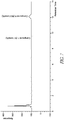
- FIGs. 3A and 3B show the HPLC traces of the reaction mixture collected in experiments 2.2 and 3.2 respectively.
- the continuous flow conduits 101 to 103 were cooled to -78 °C, while the continuous flow conduit 104 was maintained at 20 °C.
- Experiment 2.2 showed the highest conversion rate of 90% based on the calculation of the areas for compound 1 and compound A in the HPLC chart.
- the continuous flow conduits 101 to 103 were cooled to -40 ° C, while the continuous flow conduit 104 was maintained at 20° C.
- Experiment 3.2 showed a conversion rate of 10% based on the calculation of the areas for compound 1 and compound A in the HPLC chart.
- the HPLC chart of experiment 3.2 shows more impurities than that of experiment 2.2.
- the experimental set-up as schematically outlined in FIG. 2 was used except that a second portion (dual injection) of the BuLi/dichloromethane mixture was added to the reaction mixture that flowed out of the continuous flow conduit 103.
- a second portion dual injection
- the HPLC trace of the reaction mixture collected after addition of the second portion of BuLi/dichloromethane mixture shows that the ratio of compound 1 to compound A was 84:16.
- FIG. 5 shows the HPLC analysis of the reaction mixture collected from this reaction process, and the ratio of compound 1 to compound A was about 66:34 and the level of impurities was high.
- n-butyl lithium stock solution in hexane was diluted with THF to prevent precipitation at low temperatures. This stock solution was prepared and kept at -78 ° C.
- the dichloromethane/THF solution and Compound 1 in heptane solution were pre-cooled to -15 ° C. In order to avoid precipitation the ZnCl 2 solution was not pre-cooled. All other stock solutions were cooled prior to entering the pump, and then cooled again using a cooling spiral residing in the cooling bath.
- the experimental set-up 500 used here is shown in FIG. 6 .
- a continuous flow conduit 501 is used for delivering the n-butyl lithium solution
- a continuous flow conduit 502 is used for mixing the n-butyl lithium and dichloromethane reagents and for delivering the reaction mixture to the next step
- a continuous flow conduit 503 is used for combining the compound of Formula (IIa) or (IIb) and the reaction mixture that flows out of the continuous flow conduit 502
- a continuous flow conduit 504 is used for combining zinc chloride and the reaction mixture that flows out of the continuous flow conduit 503.
- the n-butyl lithium stock solution was continuously added into the reaction process from the n-butyl lithium stock solution vessel 505 through a valve 505a and the n-butyl lithium was cooled in the continuous flow conduit 501 by using a cooling bath 512; a dichloromethane stock solution in THF was continuously added into the reaction process from the dichloromethane stock solution vessel 506 through a valve 506a and was pre-cooled to -15 ° C in a continuous flow conduit 507; the mixture of n-butyl lithium and dichloromethane continuously flowed through the continuous flow conduit 502, which was cooled in the cooling bath 512; the stock solution of compound 1 was continuously added into the reaction process from the compound 1 stock solution vessel 508 through a valve 508a and was pre-cooled to -15 ° C before being combined with the reaction mixture that flowed out of the continuous flow conduit 502 in the continuous flow conduit 503, which was cooled in the cooling bath 512; the zinc chloride stock solution in THF was
- a valve such as 505a, 506a, 508a, or 510a can be used to fluidly couple an output of a vessel to an input of a continuous flow conduit.
- the starting materials were kept under nitrogen atmosphere and dry solvents (KF ⁇ 0.01%) were used to prepare the stock solutions.
- the continuous flow set-up used here was made of stainless steel and was built using 1/16" spiraled tubing (internal diameter: 1 mm).
- the system was controlled using four Gilson 307 HPLC pumps, temperature control was achieved using a cooling bath with different compositions to maintain the desired reaction temperature.
- a continuous flow conduit 001 is used for cooling and delivering the n-butyl lithium solution
- a continuous flow conduit 002 is used for combining the n-butyl lithium and dichloromethane reagents and for continuously delivering the reaction mixture to the next step
- a continuous flow conduit 003 is for used combining the compound of formula (IIa) or (IIb) and the reaction mixture that flows out of the continuous flow conduit 002.
- the zinc chloride solution is not introduced into a continuous flow conduit. Instead, the reaction stream flowing out of the continuous conduit 003 is quenched in a vessel 010 containing a pre-cooled (-20°C) zinc chloride solution (> 2 equivalents).
- the n-butyl lithium stock solution was pre-cooled to -20 ° C prior to being continuously added into the reaction process from a n-butyl lithium stock solution vessel 004 through a valve 004a and the n-butyl lithium was cooled in the continuous flow conduit 001 by using a cooling bath 009; a dichloromethane stock solution in THF was continuously added into the reaction process from a dichloromethane stock solution vessel 005 through a valve 005a and was cooled to -60 ° C in a continuous flow conduit 006, which was placed in the cooling bath 009; the mixture of n-butyl lithium and dichloromethane continuously flowed through the continuous flow conduit 002, which was cooled in the cooling bath 009; the stock solution of compound 1 was continuously added into the reaction process from a compound 1 stock solution vessel 007 and was cooled to -60 ° C before being combined with the reaction mixture that flowed out of the continuous flow conduit 002 in the
- the quenched mixture was warmed to ambient temperature and washed twice with 1M HCl followed by two washes with water.
- the product solution was concentrated by distillation under vacuum to a defined volume, diluted with THF and again concentrated by distillation under vacuum to a defined volume to remove present water.
- the compound A was obtained in THF as the final product.
- the n-butyl lithium stock solution vessel 004 was fluidly coupled to the input of the continuous flow conduit 001 through a valve 004a.
- the dichloromethane stock solution vessel 005 was fluidly coupled to the continuous flow conduit 006 through a valve 005a.
- the compound 1 stock solution vessel 007 was fluidly coupled to the continuous flow conduit 008 through a valve 007a.
- nBuLi (7.4 wt%) was prepared by diluting a 2.8M nBuLi solution in heptane with THF. For example, a flask was added with 40 mL (35.5 g) THF under inter gas protection and then cooled to ⁇ -60°C, then 14.4 g (20.3 mL) of a 2.8 M (25.6wt%) nBuLi solution in heptane was added into the flask while keeping the temperature below -60°C.
- the stock solution of dichloromethane (39.0%) in THF was prepared by mixing 90.0 ml (119.3 g) dichloromethane in 210 ml (186.3 g) THF.
- the stock solution of compound 1 was prepared by first preparing a compound 1 (77.9 g) solution in heptane (38.0 wt% of compound 1) and then adding 24.1 g of THF (density 0.813 g/ml).
- the stock solution of Zinc chloride (9.7 wt%, 0.7 M) in THF was prepared by dissolving 22.2 g of zinc chloride in 233 ml (206.7 g) of THF. Table 4.
- the flow rates shown in Table 4 correspond to 21 seconds of residence time in the continuous flow conduit 002 and 23 seconds of residence time in the continuous flow conduit 003.
- the dichloromethane flow was started first, followed by starting the flow of the compound 1 solution, and then followed by starting of the n-BuLi solution.
- a pre-run of 7 min to 10 min was performed and the reaction mixture from the pre-run and flowed through the continuous flow conduit 003 was collected, and then the reaction mixture flowing from the continuous flow conduit 003 was allowed to flow into 90 ml of zinc chloride solution (at about -20 ° C) for 15 min.
- the amount of Zinc chloride corresponded to more than 2.1 mol equivalent of compound 1.
- Regular IPC samples were taken to check conversion and side product information, and the compound 1 flow can be changed based on the IPC results. IPC was determined based on the area% of compound 1, compound A, and side product in the HPLC chromatogram.
- the reaction mixture in the zinc chloride vessel can be later washed twice with 1M HCL (46 ml for each wash), and then washed with water twice (46 ml for each wash).
- the obtained solution was concentrated by distillation under vacuum at a temperature (less than 50 ° C) to be less than about 17 ml.
- 20 mL of THF was added to the distilled product, and the solution was distilled again under vacuum to about 30 ml.
- the water content was examined by KF titration, and if the water content was not less than 0.1%, additional distillation cycle was performed to reduce the water content.
- the weight of the final product solution was measured by taking an aliquot of the product solution and concentrating the product solution to an oil, followed by degasing the oil for 30 min at 10 mbar and 50 ° C and calculating the percentage of compound A in the product solution based on the ratio of the product oil weight to the weight of the aliquot.
- the continuous flow apparatus 050 was made of stainless steel and built using 1/16" spiraled tubing (internal diameter: 1 mm).
- the additions of dichloromethane and the compound 1 solutions were controlled using four Gilson 307 HPLC pumps with internal damper, the addition of n-butyl lithium solution was controlled using Harvard App Syringe Pump 11 Plus, and the temperature control was achieved using a cooling bath Haake KT900W Cryostat to achieve the desired reaction temperature.
- Some of the parameters for the continuous flow set-up 800 is listed in Table 5.
- the continuous flow conduit 002 was 142 cm, twice-longer than the continuous flow conduit 102 in FIG. 2 and the continuous flow conduit 502 in FIG. 6
- the continuous flow conduit 003 was 315 cm, twice longer than the continuous flow conduit 103 in FIG. 2 and the continuous flow conduit 503 in FIG. 6
- the flow rate in the continuous flow conduit 002 and the continuous flow conduit 003 were also twice faster than the flow rate in the continuous flow conduits 102 and 103 in FIG. 2 and the continuous flow conduits 502 and 503 in FIG. 6 .
- the double flow and double spiral length provided better reproducibility and higher conversion.
- reaction solutions included: a solution of compound 1 (29 wt%) in heptane/THF was prepared by mixing 21.0 kg of compound 1 solution and diluting with 2.15 kg heptane and 20.2 kg of THF; a solution of DCM (39wt%) in THF was prepared by mixing 17.8 kg DCM with 27.9 kg of THF; 0.7 M zinc chloride solution was prepared by dissolving 17.51 kg ZnCl 2 in 163 kg THF; and n-BuLi stock solution in heptane/THF was prepared by cooling 44 kg of THF to -60°C and subsequently mixing with 17.5 kg n-Buli solution in heptane in 40 min at about -60°C
- the continuous flow process was conducted using the following steps: the continuous flow conduits were cooled to -60 to -70°C and the n-BuLi/THF flow was started at 7 kg/h for about 20 min until the temperature of the flow reached -25°C. Then the flow was adjusted to 2.55 kg/h. The compound 1/Heptane/THF flow was started at 3.97 kg/h. After about 15 min the DCM/THF flow was started at 1.4 kg/h. After 30 min, the reaction mixture formed following quenching in the ZnCl 2 solution (precooled to -20°C) was collected. After the reaction mixture was collected for 4 hrs, the compound 1/Heptane/THF flow was adjusted to 3.91 kg/h based on IPC results.
- the experimental set-up 900 as schematically outlined in FIG. 9 was used.
- a continuous flow conduit 901 is used for delivering butyl lithium in heptane stock solution
- a continuous flow conduit 902 is used for delivering tetrahydrofuran stock solution.
- the continuous stream of butyl lithium in heptane and the continuous stream of tetrahydrofuran were combined at an input of a continuous flow conduit 903.
- the stock solution of butyl lithium in heptane was stored in a vessel 901a, and the stock solution of tetrahydrofuran was stored in a vessel 902a.
- the stock solution of dichloromethane was stored in a vessel 906a, and a continuous flow conduit 906 was used to deliver dichloromethane to the input of the continuous flow conduit 904.
- the combined mixture of the butyl lithium in tetrahydrofuran and heptane flowing out of the continuous flow conduit 903 was combined with the continuous flow of dichloromethane at the input of a continuous flow conduit 904.
- the reaction intermediate flowing out of the output of the continuous flow conduit 904 was combined with the compound of Formula (IIa) or (IIb) at the input of a continuous flow conduit 905.
- the compound of Formula (IIa) or (IIb) in heptane was stored in a vessel 907a and delivered to the input of the continuous flow conduit 905 through a continuous flow conduit 907.
- the reaction intermediate flowing out of the output of the continuous flow conduit 905 was then collected in a vessel 910 which contained zinc chloride.
- the continuous flow conduits 901-907 were placed in a cooling bath 909, and the vessel 910 was also placed in a cooling bath.
- the vessel 901a was fluidly coupled to the continuous flow conduit 901 through a valve 901b; the vessel 902a was fluidly coupled to the continuous flow conduit 902 through a valve 902b; the vessel 906a was fluidly coupled to the continuous flow conduit 906 through a valve 906b; and the vessel 907a was fluidly coupled to the continuous flow conduit 907 through a valve 907b.
- the vessels 901a, 902a, 906a, and 907a were pressurized vessels. The flow rates of the various reagents flowing out of the vessels were adjusted through the corresponding valves 901b, 902b, 906b, and 907b.
- the continuous flow set-up used in Example 7 can be made of stainless steel spiraled tubing.
- the continuous flow conduits 901 and 902 was about 0.5 m long, the continuous flow conduit 903 was 6 m long, the continuous flow conduit 904 was in the range of about 1.5 m to 3 m long, the continuous flow conduit 905 was about 6 m long, the continuous flow conduit 906 was about 0.5 m long, and the continuous flow conduit 907 was about 0.5 m long.
- Table 7 shows the reaction parameters used in the continuous flow process.
- the tubing length and diameters can be adjusted based on the experiments scale and reaction conditions.
- the relative molar ratio of n-butyl lithium to Compound 1 as listed in the table can have a maximum deviation of 0.2. Table 7.
- IPC was used to determine the reaction conversion, and the reaction solution was evaluated based on the presence of the compound of formula (IIa) or (IIb) or the presence of a chlorine side product.
- the n-BuLi flow was increased.
- the amount of the chlorine side product exceeded the limit, the n-BuLi flow was decreased.
- the reaction intermediate that was treated with ZnCl 2 were then purified through extraction and distillation.
- the first extraction was performed using 1M HCL without delay due to the stability of the extracted product.
- the compound (Ia) or (Ib) assay was decreasing significantly within 24h.
- the impurity profile was almost unchanged.
- the second extraction was performed using 1M HCl at room temperature.
- the third extraction was performed using 5% NaHCO 3 to neutralize the HCl as all the protection groups are acid labile.
- the fourth extraction was performed with water at room temperature.
- the product from the fourth extraction was fairly stable at room temperature. After the fourth extraction, the product underwent distillation at a reduced pressure at 50 °C.
- the continuous flow process for the production of compound A described in Example 7 has achieved good reproducibility and provided high yield and high selectivity.
- Example 7 Several large scale productions were performed using the process described in Example 7. The reaction parameters have been scaled proportionally based on the amount of starting materials. The production results for compound B are summarized in Table 8 below. The continuous flow process described in Example 7 was used to produce more than 880 kg of Compound A under full cGMP, thus demonstrating the successful application of the process described herein in a large scale pharmaceutical production. Table 8. Large scale production using the continuous process in Example 7. No.
Landscapes
- Chemical & Material Sciences (AREA)
- Organic Chemistry (AREA)
- Organic Low-Molecular-Weight Compounds And Preparation Thereof (AREA)
- Pharmaceuticals Containing Other Organic And Inorganic Compounds (AREA)
Claims (15)
- Verfahren zur Herstellung einer Verbindung der Formel (Ia) oder (Ib),
 Q - (CH2)n- ist;M -CH2- oder -CH=CH- ist;n 1 oder 2 beträgt;R1 eine Carboxylschutzgruppe ist;R2 eine Hydroxylschutzgruppe ist; oderR1 und R2 zusammen mit den Atomen, an die sie angelagert sind, einen fünfgliedrigen heterocyclischen Ring bilden, der wahlweise mit C1-4-Alkyl substituiert ist;jedes R3 unabhängig unter Wasserstoff, -OH, Halogen, -CF3, C1-C6-Alkenyl, C1-C6-Alkynyl, C1-C6-Heteroalkyl, C3-C7-Carbocyclyl, 5-10-gliedrigem Heterocyclyl, C6-C10-Aryl, 5-10-gliedrigem Heteroaryl, Cyano, C1-C6-Alkoxy(C1-C6)-alkyl,C6-10-Aryloxy, Sulfhydryl (Mercapto) und -(CH2)m-Y'-(CH2)p-M' ausgewählt ist;m und p unabhängig 0 bis 3 betragen;Y' aus der Gruppe ausgewählt ist bestehend aus -S-, -S(O)-, -S(O)2-, -O-, -CR4aR5a- und -NR1a-;M' aus der Gruppe ausgewählt ist bestehend -C(O)NR1aR2a; -C(O)NR1aOR3a; -NR1aC(O)R4a; - NR1C(O)NR2aR1b; -NR1C(O)OR3a; -NR1S(O)2R3a; - NR1aS(O)2NR2aR1b; -C(=NR1a)R4a; -C(=NR1a)NR2aR1b; - NR1aCR4a(=NR2a) ; -NR1aC(=NR2a) NR1bR2b; C1-4-Alkyl, das wahlweise mit 0-2 Substituenten substituiert ist ausgewählt aus der Gruppe bestehend aus -OR3a,-NR1aR2a, Halogen, -C(O)NR1aR2a und -NR1aC(O)R4a; C3-10-Cycloalkyl, das wahlweise mit 0-2 Substituenten substituiert ist ausgewählt aus der Gruppe bestehend aus C1-C4-Alkyl, -OR3a, -NR1aR2a, Halogen, -C(O)NR1aR2a und -NR1aC(O)R4a; C6-10-Aryl, das wahlweise mit 0-2 Substituenten substituiert ist ausgewählt aus der Gruppe bestehend aus C1-4-Alkyl, -OR3a, -NR1aR2a, Halogen, -C(O)NR1aR2a und - NR1aC(O)R4a; 5- bis 10-gliedrigem Heteroaryl, das wahlweise mit 0-2 Substituenten substituiert ist ausgewählt aus der Gruppe bestehend aus C1-4-Alkyl, -OR3a, -NR1aR2a, Halogen, -C(O)NR1aR2a und - NR1aC(O)R4a; und 4- bis 10-gliedrigem Heterocyclyl, das wahlweise mit 0-2 Substituenten substituiert ist ausgewählt aus der Gruppe bestehend aus C1-4-Alkyl, -OR3a, -NR1aR2a, Halogen, C(O)NR1aR2a und - NR1aC(O)R4a;jedes R1a, R2a, R1b und R2b unabhängig aus der Gruppe ausgewählt ist bestehend aus -H, wahlweise substituiertem C1-10-Alkyl, wahlweise substituiertem C2-10-Alkenyl, wahlweise substituiertem C2-10-Alkynyl, wahlweise substituiertem C3-7-Cycloalkyl, wahlweise substituiertem 3-8-gliedrigem Heterocyclyl, wahlweise substituiertem C6-10-Aryl und wahlweise substituiertem 5-10-gliedrigem Heteroaryl;R3a Wasserstoff, wahlweise substituiertes C1-10-Alkyl, wahlweise substituiertes C1-10-Alkyl-COOH, wahlweise substituiertes C2-10-Alkenyl, wahlweise substituiertes C2-10-Alkynyl, wahlweise substituiertes C3-7-Cycloalkyl, wahlweise substituiertes 3-8-gliedrigesm Heterocyclyl, wahlweise substituiertes C6-10-Aryl und wahlweise substituiertes 5-10-gliedriges Heteroaryl ist; undjedes R4a und R5a aus der Gruppe ausgewählt ist bestehend aus -H, -OH, wahlweise substituiertem Alkoxyl, wahlweise substituiertem C1-10-Alkyl, wahlweise substituiertem C2-10-Alkenyl, wahlweise substituiertem C2-10-Alkynyl, wahlweise substituiertem C3-7-Cycloalkyl, wahlweise substituiertem 3-8-gliedrigem Heterocyclyl, wahlweise substituiertem C6-10-Aryl und wahlweise substituiertem 5-10-gliedrigem Heteroaryl;wobei das Verfahren Folgendes umfasst:Bereitstellen eines ersten kontinuierlichen Stroms von Alkyllithium;Bereitstellen eines kontinuierlichen Stroms von Dichlormethan;Kombinieren des ersten kontinuierlichen Stroms von Alkyllithium und des kontinuierlichen Stroms von Dichlormethan an einer Eingabe einer Leitung eines ersten kontinuierlichen Stroms, um einen kontinuierlichen Strom aus einem ersten Reaktion Zwischenprodukt an einem Auslass der Leitung des ersten kontinuierlichen Stroms zu ergeben;Bereitstellen eines kontinuierlichen Stroms einer Verbindung der Formel (IIa) oder (IIb);
 Kombinieren des kontinuierlichen Stroms des ersten Reaktionszwischenprodukts und des kontinuierlichen Stroms der Verbindung der Formel (IIa) oder (IIb) an einer Eingabe einer Leitung des zweiten kontinuierlichen Stroms, um ein zweites Reaktionszwischenprodukt an einem Auslass der Leitung des zweiten kontinuierlichen Stroms zu ergeben; undAuffangen des zweiten Reaktionszwischenprodukts am Auslass der Leitung des zweiten kontinuierlichen Stroms und Behandeln mit einer Lewis-Säure, um die Verbindung der Formel (Ia) oder (Ib) zu ergeben.
 - Verfahren nach Anspruch 1, wobei das zweite Reaktionszwischenprodukt in einem Gefäß gesammelt wird und das Gefäß keinen kontinuierlichen Ausfluss aufweist.
- Verfahren nach Anspruch 1 oder 2, wobei das Bereitstellen des ersten kontinuierlichen Stroms von Alkyllithium ferner Folgendes umfasst
Bereitstellen eines kontinuierlichen Stroms von Tetrahydrofuran;
Bereitstellen eines zweiten kontinuierlichen Stroms von Alkyllithium; und
Kombinieren des kontinuierlichen Stroms von Tetrahydrofuran und des zweiten kontinuierlichen Stroms von Alkyllithium an der Eingabe einer Leitung eines dritten kontinuierlichen Stroms, um den ersten kontinuierlichen Strom von Alkyllithium zu bilden; und
wobei der erste kontinuierliche Strom von Alkyllithium ein kontinuierlicher Strom von Alkyllithium in Hexan Tetrahydrofuran ist. - Verfahren nach irgendeinem der Ansprüche 1 - 3, wobei der zweite kontinuierliche Strom von Alkyllithium in Heptan erfolgt; wobei der kontinuierliche Strom von Dichlormethan ein kontinuierlicher Strom von Dichlormethan in Tetrahydrofuran ist und wobei der kontinuierliche Strom der Verbindung der Formel (IIa) oder (IIb) ein kontinuierlicher Strom der Verbindung der Formel (IIa) oder (IIb) in Heptan ist.
- Verfahren nach irgendeinem der Ansprüche 1 bis 4, wobei das Alkyllithium, das Dichlormethan, die Verbindung der Formel (IIa) oder (IIb) und die Lewis-Säure weniger als 0,5 % Wasser enthalten, wobei das Alkyllithium n-Butyllithium ist und die Lewis-Säure Zinkchlorid ist.
- Verfahren nach irgendeinem der Ansprüche 1 bis 5, umfassend mindestens einen Schritt ausgewählt unter: 1) Vorkühlen mindestens eines Mittels ausgewählt unter dem Alkyllithium, dem Dichlormethan und der Verbindung der Formel (IIa) oder (IIb) auf eine Temperatur im Bereich von -80 °C bis -65 °C, bevorzugt -70 °C vor Kombinieren des ersten kontinuierlichen Stroms von Alkyllithium und des kontinuierlichen Stroms von Dichlormethan; 2) Vorkühlen der Lewis-Säure auf eine Temperatur von -20 °C vor dem Behandeln, 3) Halten der Leitung des ersten kontinuierlichen Stroms bei einer Temperatur im Bereich von -80 °C bis -65 °C, bevorzugt bei -70 °C; und 4) Halten der Leitung des zweiten kontinuierlichen Stroms bei einer Temperatur im Bereich von -80 °C bis -65 °C, bevorzugt bei -70 °C.
- Verfahren nach irgendeinem der Ansprüche 1 bis 6, wobei das Molverhältnis von Alkyllithium zu Chlormethan im Bereich von 1:1 bis 1:10, bevorzugt 1:3 bis 1:4 liegt; wobei das Molverhältnis von Alkyllithium zu Chlormethan 1:3 bis 1:4, bevorzugt 0,5:1 bis 5:1 beträgt; wobei das Molverhältnis von Alkyllithium zu der Verbindung der Formel (IIa) oder (IIb) im Bereich von 0,5:1 bis 5:1, bevorzugt 1:1 bis 1, 2:1 liegt; und wobei das Molverhältnis von Lewis-Säure zu der Verbindung der Formel (IIa) oder (IIb) im Bereich von 0,5:1 bis 5:1, bevorzugt 1:1 bis 1,5:1 liegt.
- Verfahren nach irgendeinem der Ansprüche 1 bis 7, umfassend mindestens einen der Schritte ausgewählt von: 1) Strömenlassen des Alkyllithiums in die erste Leitung des ersten kontinuierlichen Stroms mit einer Strömungsrate von 0,1 mMol/min bis 5,0 mMol/min, bevorzugt 0,8 mMol/min bis 2,7 mMol/min; 2) Strömenlassen des Dichlormethans in die Leitung des ersten kontinuierlichen Stroms mit einer Strömungsrate von 1 mMol/min bis 5 mMol/min, bevorzugt 2,5 mMol/min bis 3,0 mMol/min; und 3) Strömenlassen der Verbindung der Formel (IIa) oder (IIb) in die Leitung des zweiten kontinuierlichen Stroms mit einer Strömungsrate von 0,1 mMol/min bis 5 mMol/min, bevorzugt 2,0 mMol/min.
- Verfahren nach irgendeinem der Ansprüche 1 bis 8, wobei das Behandeln des zweiten Reaktionszwischenprodukts mit dem Zinkchlorid nicht in einer Leitung für kontinuierlichen Strom ausgeführt wird.
- Verfahren nach irgendeinem der Ansprüche 1 bis 9, ferner mindestens einen Schritt umfassend ausgewählt unter:1) Kombinieren von Alkyllithium in Heptan und Tetrahydrofuran, um eine Alkyllithiumstammlösung für den ersten kontinuierlichen Strom von Alkyllithium herzustellen und Unterdrucksetzen eines Gefäßes, das die Alkyllithiumstammlösung umfasst;2) Herstellen einer Stammlösung von Alkyllithium in Heptan und Unterdrucksetzen eines Gefäßes, das die Stammlösung von Alkyllithium in Heptan umfasst;3) Herstellen einer Stammlösung von Tetrahydrofuran und Unterdrucksetzen eines Gefäßes, das die Stammlösung von Tetrahydrofuran umfasst;4) Kombinieren von Dichlormethan und Tetrahydrofuran, um eine Dichlormethanstammlösungen für den kontinuierlichen Strom von Dichlormethan bereitzustellen und Unterdrucksetzen eines Gefäßes, das die Dichlormethanstammlösung umfasst;5) Kombinieren der Verbindung der Formel (IIa) oder (IIb) und von Heptan, um eine Stammlösung der Verbindung der Formel (IIa) oder (IIb) bereitzustellen und Unterdrucksetzen eines Gefäßes, das die Stammlösung der Verbindung der Formel (IIa) oder (IIb) umfasst; und6) Kombinieren der Lewis-Säure und von Tetrahydrofuran, um eine Lewis-Säure-Stammlösung bereitzustellen und Unterdrucksetzen eines Gefäßes, das die Lewis-Säure-Stammlösung umfasst.
- Verfahren nach irgendeinem der Ansprüche 1 bis 10, umfassend das Herstellen einer Verbindung der Formel (Ia), wobei M -CH=CH- ist und n 1 beträgt oder M -CH2- ist und Q -CH2- oder -CH2-CH2- ist; oder Herstellen einer Verbindung der Formel Ib, wobei R1 tert-Butyldimethylsilyl ist und R2 tert-Butyl ist.
- Verfahren nach irgendeinem der Ansprüche 1 bis 10, umfassend das Herstellen einer Verbindung der Formel Ib, wobei die Verbindung der Formel Ib die Struktur der Formel III aufweist:

- Verfahren nach irgendeinem der Ansprüche 1 bis 10, wobei die Verbindung der Formel Ia Folgendes ist:

- Verfahren nach irgendeinem der Ansprüche 1 bis 10, wobei die Verbindung der Formel Ia die Struktur von


- Vorrichtung für die Herstellung einer Verbindung der Formel Ia oder Ib,
 Q - (CH2)n- ist;M -CH2- oder -CH=CH- ist;n 1 oder 2 beträgt;R1 eine Carboxylschutzgruppe ist;R2 eine Hydroxylschutzgruppe ist; oderR1 und R2 zusammen mit den Atomen, an die sie angelagert sind, einen fünfgliedrigen heterocyclischen Ring bilden, der wahlweise mit C1-4-Alkyl substituiert ist;jedes R3 unabhängig unter Wasserstoff, -OH, Halogen, -CF3, C1-C6-Alkenyl, C1-C6-Alkynyl, C1-C6-Heteroalkyl, C3-C7-Carbocyclyl, 5-10-gliedrigem Heterocyclyl, C6-10-Aryl, 5-10-gliedrigem Heteroaryl, Cyano, C1-C6-Alkoxy(C1-C6) -alkyl, C6-10-Aryloxy, Sulfhydryl (Mercapto) und -(CH2)m-Y'-(CH2)p-M' ausgewählt ist;m und p unabhängig 0 bis 3 betragen;Y' aus der Gruppe ausgewählt ist bestehend aus -S-, -S(O)-, -S(O)2-, -O-, -CR4aR5a- und -NR1a- ;M' aus der Gruppe ausgewählt ist bestehend -C(O)NR1aR2a; -C(O)NR1aOR3a; -NR1aC(O)R4a; -NR1C(O)NR2aR1b; -NR1C(O)OR3a; -NR1S(O)2R3a; -NR1aS(O)2NR2aR1b; -C(=NR1a)R4a; -C(=NR1a)NR2aR1b; -NR1aCR4a (=NR2a); -NR1aC(=NR2a)NR1bR2b; C1-4-Alkyl, das wahlweise mit 0-2 Substituenten substituiert ist ausgewählt aus der Gruppe bestehend aus -OR3a, -NR1aR2a, Halogen, -C(O)NR1aR2a und -NR1aC(O)R4a; C3-10-Cycloalkyl, das wahlweise mit 0-2 Substituenten substituiert ist ausgewählt aus der Gruppe bestehend aus C1-4-Alkyl, -OR3a,-NR1aR2a, Halogen, -C(O)NR1aR2a und -NR1aC(O)R4a; C6-10-Aryl, das wahlweise mit 0-2 Substituenten substituiert ist ausgewählt aus der Gruppe bestehend aus C1-4-Alkyl, -OR3a, -NR1aR2a, Halogen, -C(O)NR1aR2a und -NR1aC(O)R4a; 5- bis 10-gliedrigem Heteroaryl, das wahlweise mit 0-2 Substituenten substituiert ist ausgewählt aus der Gruppe bestehend aus C1-4-Alkyl, -OR3a, -NR1aR2a, Halogen, -C(O)NR1aR2a und -NR1aC(O)R4a; und 4- bis 10-gliedrigem Heterocyclyl, das wahlweise mit 0-2 Substituenten substituiert ist ausgewählt aus der Gruppe bestehend aus C1-4-Alkyl, -OR3a, -NR1aR2a, Halogen, C(O)NRaR2a und -NR1aC(O)R4a;jedes R1a, R2a, R1b und R2b unabhängig aus der Gruppe ausgewählt ist bestehend aus -H, wahlweise substituiertem C1-10-Alkyl, wahlweise substituiertem C2-10-Alkenyl, wahlweise substituiertem C2-10-Alkynyl, wahlweise substituiertem C3-7-Cycloalkyl, wahlweise substituiertem 3-8-gliedrigem Heterocyclyl, wahlweise substituiertem C6-10-Aryl und wahlweise substituiertem 5-10-gliedrigem Heteroaryl;R3a Wasserstoff, wahlweise substituiertes C1-10-Alkyl, wahlweise substituiertes C1-10-Alkyl-COOH, wahlweise substituiertes C2-10-Alkenyl, wahlweise substituiertes C2-10-Alkynyl, wahlweise substituiertes C3-7-Cycloalkyl, wahlweise substituiertes 3-8-gliedrigesm Heterocyclyl, wahlweise substituiertes C6-10-Aryl und wahlweise substituiertes 5-10-gliedriges Heteroaryl ist; undjedes R4a und R5a aus der Gruppe ausgewählt ist bestehend aus -H, -OH, wahlweise substituiertem Alkoxyl, wahlweise substituiertem C1-10-Alkyl, wahlweise substituiertem C2-10-Alkenyl, wahlweise substituiertem C2-10-Alkynyl, wahlweise substituiertem C3-7-Cycloalkyl, wahlweise substituiertem 3-8-gliedrigem Heterocyclyl, wahlweise substituiertem C6-10-Aryl und wahlweise substituiertem 5-10-gliedrigem Heteroaryl;Vorrichtung umfassend:ein erstes Gefäß, da eine Ausgabe aufweist und Alkyllithium umfasst;ein zweites Gefäß, das eine Ausgabe aufweist und Dichlormethan umfasst;eine Leitung des ersten kontinuierlichen Stroms umfassend eine Eingabe und eine Ausgabe, wobei die Eingabe der Leitung des ersten kontinuierlichen Stroms fluid an die Ausgabe des ersten Gefäßes und die Ausgabe des zweiten Gefäßes angeschlossen;ein drittes Gefäß, das eine Ausgabe aufweist und eine Verbindung der Formel (IIa) oder (IIb) umfasst
 eine zweite kontinuierliche Leitung, die eine Eingabe und eine Ausgabe umfasst, wobei die Eingabe der zweiten kontinuierlichen Leitung fluid an die Ausgabe der Leitung des ersten kontinuierlichen Stroms und die Ausgabe des dritten Gefäßes angeschlossen ist;ein viertes Gefäß, das eine Eingabe aufweist, die fluid an die Ausgabe der Leitung des zweiten kontinuierlichen Stroms angeschlossen ist und eine Lewis-Säure umfasst.
Applications Claiming Priority (2)
| Application Number | Priority Date | Filing Date | Title |
|---|---|---|---|
| US201462094886P | 2014-12-19 | 2014-12-19 | |
| PCT/US2015/064770 WO2016100043A1 (en) | 2014-12-19 | 2015-12-09 | Apparatus and continuous flow process for production of boronic acid derivatives |
Publications (3)
| Publication Number | Publication Date |
|---|---|
| EP3233869A1 EP3233869A1 (de) | 2017-10-25 |
| EP3233869A4 EP3233869A4 (de) | 2018-06-27 |
| EP3233869B1 true EP3233869B1 (de) | 2019-09-25 |
Family
ID=56127374
Family Applications (1)
| Application Number | Title | Priority Date | Filing Date |
|---|---|---|---|
| EP15870720.8A Active EP3233869B1 (de) | 2014-12-19 | 2015-12-09 | Vorrichtung und durchflussverfahren zur herstellung von borsäurederivaten |
Country Status (6)
| Country | Link |
|---|---|
| US (1) | US10364257B2 (de) |
| EP (1) | EP3233869B1 (de) |
| CN (1) | CN107207537B (de) |
| ES (1) | ES2761778T3 (de) |
| IL (1) | IL252682A0 (de) |
| WO (1) | WO2016100043A1 (de) |
Families Citing this family (11)
| Publication number | Priority date | Publication date | Assignee | Title |
|---|---|---|---|---|
| AU2013355110B2 (en) | 2012-12-07 | 2017-11-09 | VenatoRx Pharmaceuticals, Inc. | Beta-lactamase inhibitors |
| EP2943204B1 (de) | 2013-01-10 | 2019-03-13 | Venatorx Pharmaceuticals Inc | Beta-lactamase-hemmer |
| WO2015191907A1 (en) | 2014-06-11 | 2015-12-17 | VenatoRx Pharmaceuticals, Inc. | Beta-lactamase inhibitors |
| WO2018027062A1 (en) | 2016-08-04 | 2018-02-08 | VenatoRx Pharmaceuticals, Inc. | Boron-containing compounds |
| JOP20190188A1 (ar) | 2017-02-01 | 2019-08-01 | Rempex Pharmaceuticals Inc | جهاز وعملية تدفق مستمرة لإنتاج مشتق حمض بورونيك |
| KR102603489B1 (ko) | 2017-03-06 | 2023-11-16 | 에버레스트 메디신즈 (싱가포르) 피티이. 리미티드 | 베타-락타마제 억제제를 포함하는 고체 형태 및 조합 조성물과 이의 용도 |
| US11332485B2 (en) | 2017-05-26 | 2022-05-17 | VenatoRx Pharmaceuticals, Inc. | Penicillin-binding protein inhibitors |
| US11267826B2 (en) | 2017-05-26 | 2022-03-08 | VenatoRx Pharmaceuticals, Inc. | Penicillin-binding protein inhibitors |
| WO2019226931A1 (en) | 2018-05-25 | 2019-11-28 | VenatoRx Pharmaceuticals, Inc. | Penicillin-binding protein inhibitors |
| BR112021010095A2 (pt) | 2018-11-29 | 2021-09-28 | VenatoRx Pharmaceuticals, Inc. | Composições de combinação que compreendem um inibidor de beta-lactamase e usos das mesmas |
| CN112604618A (zh) * | 2020-12-18 | 2021-04-06 | 成都睿和德医药科技有限公司 | 连续流反应器在硼酸合成中的应用 |
Family Cites Families (27)
| Publication number | Priority date | Publication date | Assignee | Title |
|---|---|---|---|---|
| US4194047A (en) | 1975-11-21 | 1980-03-18 | Merck & Co., Inc. | Substituted N-methylene derivatives of thienamycin |
| US4260543A (en) | 1978-07-03 | 1981-04-07 | Merck & Co., Inc. | Crystalline N-formimidoyl thienamycin |
| US4409214A (en) | 1979-11-19 | 1983-10-11 | Fujisawa Pharmaceutical, Co., Ltd. | 7-Acylamino-3-vinylcephalosporanic acid derivatives and processes for the preparation thereof |
| US4783443A (en) | 1986-03-03 | 1988-11-08 | The University Of Chicago | Amino acyl cephalosporin derivatives |
| CA1283404C (en) | 1986-07-01 | 1991-04-23 | Shigeru Sanai | Cephalosporin compounds, processes for their preparation and antibacterial agents |
| ZA893284B (en) | 1988-05-04 | 1990-03-28 | Igen Inc | Peptide analogs and their use as haptens to elicit catalytic antibodies |
| US5442100A (en) | 1992-08-14 | 1995-08-15 | The Procter & Gamble Company | β-aminoalkyl and β-N-peptidylaminoalkyl boronic acids |
| US5888998A (en) | 1997-04-24 | 1999-03-30 | Synphar Laboratories, Inc. | 2-oxo-1-azetidine sulfonic acid derivatives as potent β-lactamase inhibitors |
| US6916803B2 (en) | 2000-09-14 | 2005-07-12 | Pantherix, Ltd. | 3-(Heteroaryl acetamido)-2-oxo-azetidine-1-sulfonic acids derivatives as antibacterial agents |
| US7271186B1 (en) | 2002-12-09 | 2007-09-18 | Northwestern University | Nanomolar β-lactamase inhibitors |
| GB0719366D0 (en) | 2007-10-03 | 2007-11-14 | Smithkline Beecham Corp | Compounds |
| CA2705393A1 (en) | 2007-11-13 | 2009-05-22 | Protez Pharmaceuticals, Inc. | Beta-lactamase inhibitors |
| US20100292185A1 (en) | 2009-05-12 | 2010-11-18 | Burns Christopher J | Beta-lactamase inhibitors |
| US9278135B2 (en) | 2010-04-26 | 2016-03-08 | Chimerix Inc. | Methods of treating retroviral infections and related dosage regimes |
| CA2807546C (en) | 2010-08-10 | 2022-08-23 | Rempex Pharmaceuticals, Inc. | Cyclic boronic acid ester derivatives and therapeutic uses thereof |
| WO2013033461A1 (en) * | 2011-08-31 | 2013-03-07 | Rempex Pharmaceuticals, Inc. | Heterocyclic boronic acid ester derivatives and therapeutic uses thereof |
| WO2013053372A1 (en) | 2011-10-13 | 2013-04-18 | Therabor Pharmaceuticals | Boronic acid inhibitors of beta-lactamases |
| EP2814483A2 (de) | 2012-02-15 | 2014-12-24 | Rempex Pharmaceuticals, Inc. | Verfahren zur behandlung von bakterieninfektionen |
| AU2013355110B2 (en) * | 2012-12-07 | 2017-11-09 | VenatoRx Pharmaceuticals, Inc. | Beta-lactamase inhibitors |
| US9101638B2 (en) * | 2013-01-04 | 2015-08-11 | Rempex Pharmaceuticals, Inc. | Boronic acid derivatives and therapeutic uses thereof |
| MX2015008627A (es) * | 2013-01-04 | 2015-09-23 | Rempex Pharmaceuticals Inc | Derivados de acido boronico y usos terapeuticos de los mismos. |
| US9241947B2 (en) | 2013-01-04 | 2016-01-26 | Rempex Pharmaceuticals, Inc. | Boronic acid derivatives and therapeutic uses thereof |
| US8999885B2 (en) | 2013-01-09 | 2015-04-07 | General Electric Company | Methods of activating charcoal resulting from biomass gasification |
| EP2943204B1 (de) | 2013-01-10 | 2019-03-13 | Venatorx Pharmaceuticals Inc | Beta-lactamase-hemmer |
| ES2750805T3 (es) | 2014-05-05 | 2020-03-27 | Rempex Pharmaceuticals Inc | Síntesis de sales de boronato y usos de las mismas |
| US9511142B2 (en) | 2014-06-11 | 2016-12-06 | VenatoRx Pharmaceuticals, Inc. | Beta-lactamase inhibitors |
| WO2015191907A1 (en) | 2014-06-11 | 2015-12-17 | VenatoRx Pharmaceuticals, Inc. | Beta-lactamase inhibitors |
-
2015
- 2015-12-09 EP EP15870720.8A patent/EP3233869B1/de active Active
- 2015-12-09 US US15/537,378 patent/US10364257B2/en active Active
- 2015-12-09 CN CN201580072622.8A patent/CN107207537B/zh active Active
- 2015-12-09 WO PCT/US2015/064770 patent/WO2016100043A1/en not_active Ceased
- 2015-12-09 ES ES15870720T patent/ES2761778T3/es active Active
-
2017
- 2017-06-05 IL IL252682A patent/IL252682A0/en unknown
Non-Patent Citations (1)
| Title |
|---|
| None * |
Also Published As
| Publication number | Publication date |
|---|---|
| CN107207537B (zh) | 2019-05-31 |
| WO2016100043A1 (en) | 2016-06-23 |
| EP3233869A1 (de) | 2017-10-25 |
| IL252682A0 (en) | 2017-08-31 |
| US20170369512A1 (en) | 2017-12-28 |
| EP3233869A4 (de) | 2018-06-27 |
| US10364257B2 (en) | 2019-07-30 |
| ES2761778T3 (es) | 2020-05-21 |
| CN107207537A (zh) | 2017-09-26 |
Similar Documents
| Publication | Publication Date | Title |
|---|---|---|
| EP3233869B1 (de) | Vorrichtung und durchflussverfahren zur herstellung von borsäurederivaten | |
| AU2016311426B2 (en) | Compounds and compositions useful for treating disorders related to NTRK | |
| CN102046645B (zh) | 螺酮缩醇衍生物的结晶及其制备方法 | |
| CN113248508A (zh) | N-保护的杂环类化合物、其制备方法及其用于制备c-核苷衍生物的方法 | |
| CN110446710B (zh) | 制备btk抑制剂的方法 | |
| JP6735000B1 (ja) | マイタンシノールをアシル化する改善された方法 | |
| RS56343B1 (sr) | Kristalni (1r,4r)-6'-fluoro-n,n-dimetil-4-fenil-4',9'-dihidro-3'h-spiro[cikloheksan-1,1'-pirano[3,4,b]indol]-4-amin | |
| US20220204534A1 (en) | Apparatus and continuous flow process for production of boronic acid derivative | |
| KR102312803B1 (ko) | 불소화 탄화수소의 제조 방법 | |
| Klein et al. | Synthesis of ring B-rearranged taxane analogs | |
| JP2022542143A (ja) | 合成カンナビノールおよびその相同体を調製する方法 | |
| Rey et al. | Total synthesis and establishment of the absolute stereochemistry of (+)-mostueine. Addition of chiral nucleophiles to 3, 4-dihydro-2-methyl-9-(p-toluenesulfonyl)-β-carbolinium iodide | |
| KR20150048762A (ko) | 술포닐아미딘 화합물의 제조법 | |
| HK40096472A (zh) | 用於生产硼酸衍生物的装置 | |
| EP3442956B1 (de) | Prozess zur herstellung von pyrvinium pamoat und kristalline formen davon | |
| WO2025161144A1 (zh) | 芳基杂环类Kv1.3抑制剂及其制备方法和用途 | |
| Tanaka et al. | Regio-and stereoselective synthesis of tetrasubstituted (E)-(2-chloro-2-fluoro-1-iodovinyl) dimethylphenylsilane and its desilylative sonogashira coupling | |
| CN120441565A (zh) | 一种阿齐沙坦酯钾盐的制备方法 | |
| Suarez-Castillo et al. | Synthesis of indolylindolines mediated by t-BuNH2 | |
| CN119948022A (zh) | 用于生产大环内酯类化合物的方法 | |
| KR20240013791A (ko) | 벤족사제핀 옥사졸리디논 화합물을 제조하기 위한 공정 | |
| HK1154589B (en) | Crystal of spiroketal derivative, and process for production thereof | |
| PL430584A1 (pl) | 1,2-difenylobenzo[1,2-j]koronen oraz sposób jego otrzymywania | |
| CN110963956A (zh) | 一种苯丙胺类新生物碱的制备方法 | |
| WO2019166019A1 (zh) | 吡喃稠环类化合物、其制备方法和用途 |
Legal Events
| Date | Code | Title | Description |
|---|---|---|---|
| STAA | Information on the status of an ep patent application or granted ep patent |
Free format text: STATUS: THE INTERNATIONAL PUBLICATION HAS BEEN MADE |
|
| PUAI | Public reference made under article 153(3) epc to a published international application that has entered the european phase |
Free format text: ORIGINAL CODE: 0009012 |
|
| STAA | Information on the status of an ep patent application or granted ep patent |
Free format text: STATUS: REQUEST FOR EXAMINATION WAS MADE |
|
| 17P | Request for examination filed |
Effective date: 20170718 |
|
| AK | Designated contracting states |
Kind code of ref document: A1 Designated state(s): AL AT BE BG CH CY CZ DE DK EE ES FI FR GB GR HR HU IE IS IT LI LT LU LV MC MK MT NL NO PL PT RO RS SE SI SK SM TR |
|
| AX | Request for extension of the european patent |
Extension state: BA ME |
|
| DAV | Request for validation of the european patent (deleted) | ||
| DAX | Request for extension of the european patent (deleted) | ||
| A4 | Supplementary search report drawn up and despatched |
Effective date: 20180525 |
|
| RIC1 | Information provided on ipc code assigned before grant |
Ipc: C07F 5/02 20060101AFI20180518BHEP |
|
| GRAP | Despatch of communication of intention to grant a patent |
Free format text: ORIGINAL CODE: EPIDOSNIGR1 |
|
| STAA | Information on the status of an ep patent application or granted ep patent |
Free format text: STATUS: GRANT OF PATENT IS INTENDED |
|
| RAP1 | Party data changed (applicant data changed or rights of an application transferred) |
Owner name: REMPEX PHARMACEUTICALS, INC. |
|
| INTG | Intention to grant announced |
Effective date: 20190401 |
|
| GRAS | Grant fee paid |
Free format text: ORIGINAL CODE: EPIDOSNIGR3 |
|
| GRAA | (expected) grant |
Free format text: ORIGINAL CODE: 0009210 |
|
| STAA | Information on the status of an ep patent application or granted ep patent |
Free format text: STATUS: THE PATENT HAS BEEN GRANTED |
|
| AK | Designated contracting states |
Kind code of ref document: B1 Designated state(s): AL AT BE BG CH CY CZ DE DK EE ES FI FR GB GR HR HU IE IS IT LI LT LU LV MC MK MT NL NO PL PT RO RS SE SI SK SM TR |
|
| REG | Reference to a national code |
Ref country code: GB Ref legal event code: FG4D |
|
| REG | Reference to a national code |
Ref country code: CH Ref legal event code: EP |
|
| REG | Reference to a national code |
Ref country code: DE Ref legal event code: R096 Ref document number: 602015038851 Country of ref document: DE |
|
| REG | Reference to a national code |
Ref country code: AT Ref legal event code: REF Ref document number: 1183724 Country of ref document: AT Kind code of ref document: T Effective date: 20191015 |
|
| REG | Reference to a national code |
Ref country code: IE Ref legal event code: FG4D |
|
| REG | Reference to a national code |
Ref country code: NL Ref legal event code: MP Effective date: 20190925 |
|
| PG25 | Lapsed in a contracting state [announced via postgrant information from national office to epo] |
Ref country code: LT Free format text: LAPSE BECAUSE OF FAILURE TO SUBMIT A TRANSLATION OF THE DESCRIPTION OR TO PAY THE FEE WITHIN THE PRESCRIBED TIME-LIMIT Effective date: 20190925 Ref country code: HR Free format text: LAPSE BECAUSE OF FAILURE TO SUBMIT A TRANSLATION OF THE DESCRIPTION OR TO PAY THE FEE WITHIN THE PRESCRIBED TIME-LIMIT Effective date: 20190925 Ref country code: BG Free format text: LAPSE BECAUSE OF FAILURE TO SUBMIT A TRANSLATION OF THE DESCRIPTION OR TO PAY THE FEE WITHIN THE PRESCRIBED TIME-LIMIT Effective date: 20191225 Ref country code: SE Free format text: LAPSE BECAUSE OF FAILURE TO SUBMIT A TRANSLATION OF THE DESCRIPTION OR TO PAY THE FEE WITHIN THE PRESCRIBED TIME-LIMIT Effective date: 20190925 Ref country code: FI Free format text: LAPSE BECAUSE OF FAILURE TO SUBMIT A TRANSLATION OF THE DESCRIPTION OR TO PAY THE FEE WITHIN THE PRESCRIBED TIME-LIMIT Effective date: 20190925 Ref country code: NO Free format text: LAPSE BECAUSE OF FAILURE TO SUBMIT A TRANSLATION OF THE DESCRIPTION OR TO PAY THE FEE WITHIN THE PRESCRIBED TIME-LIMIT Effective date: 20191225 |
|
| REG | Reference to a national code |
Ref country code: LT Ref legal event code: MG4D |
|
| PG25 | Lapsed in a contracting state [announced via postgrant information from national office to epo] |
Ref country code: RS Free format text: LAPSE BECAUSE OF FAILURE TO SUBMIT A TRANSLATION OF THE DESCRIPTION OR TO PAY THE FEE WITHIN THE PRESCRIBED TIME-LIMIT Effective date: 20190925 Ref country code: GR Free format text: LAPSE BECAUSE OF FAILURE TO SUBMIT A TRANSLATION OF THE DESCRIPTION OR TO PAY THE FEE WITHIN THE PRESCRIBED TIME-LIMIT Effective date: 20191226 Ref country code: LV Free format text: LAPSE BECAUSE OF FAILURE TO SUBMIT A TRANSLATION OF THE DESCRIPTION OR TO PAY THE FEE WITHIN THE PRESCRIBED TIME-LIMIT Effective date: 20190925 |
|
| REG | Reference to a national code |
Ref country code: AT Ref legal event code: MK05 Ref document number: 1183724 Country of ref document: AT Kind code of ref document: T Effective date: 20190925 |
|
| PG25 | Lapsed in a contracting state [announced via postgrant information from national office to epo] |
Ref country code: NL Free format text: LAPSE BECAUSE OF FAILURE TO SUBMIT A TRANSLATION OF THE DESCRIPTION OR TO PAY THE FEE WITHIN THE PRESCRIBED TIME-LIMIT Effective date: 20190925 Ref country code: PT Free format text: LAPSE BECAUSE OF FAILURE TO SUBMIT A TRANSLATION OF THE DESCRIPTION OR TO PAY THE FEE WITHIN THE PRESCRIBED TIME-LIMIT Effective date: 20200127 Ref country code: PL Free format text: LAPSE BECAUSE OF FAILURE TO SUBMIT A TRANSLATION OF THE DESCRIPTION OR TO PAY THE FEE WITHIN THE PRESCRIBED TIME-LIMIT Effective date: 20190925 Ref country code: AL Free format text: LAPSE BECAUSE OF FAILURE TO SUBMIT A TRANSLATION OF THE DESCRIPTION OR TO PAY THE FEE WITHIN THE PRESCRIBED TIME-LIMIT Effective date: 20190925 Ref country code: RO Free format text: LAPSE BECAUSE OF FAILURE TO SUBMIT A TRANSLATION OF THE DESCRIPTION OR TO PAY THE FEE WITHIN THE PRESCRIBED TIME-LIMIT Effective date: 20190925 Ref country code: EE Free format text: LAPSE BECAUSE OF FAILURE TO SUBMIT A TRANSLATION OF THE DESCRIPTION OR TO PAY THE FEE WITHIN THE PRESCRIBED TIME-LIMIT Effective date: 20190925 Ref country code: AT Free format text: LAPSE BECAUSE OF FAILURE TO SUBMIT A TRANSLATION OF THE DESCRIPTION OR TO PAY THE FEE WITHIN THE PRESCRIBED TIME-LIMIT Effective date: 20190925 |
|
| REG | Reference to a national code |
Ref country code: ES Ref legal event code: FG2A Ref document number: 2761778 Country of ref document: ES Kind code of ref document: T3 Effective date: 20200521 |
|
| PG25 | Lapsed in a contracting state [announced via postgrant information from national office to epo] |
Ref country code: SM Free format text: LAPSE BECAUSE OF FAILURE TO SUBMIT A TRANSLATION OF THE DESCRIPTION OR TO PAY THE FEE WITHIN THE PRESCRIBED TIME-LIMIT Effective date: 20190925 Ref country code: CZ Free format text: LAPSE BECAUSE OF FAILURE TO SUBMIT A TRANSLATION OF THE DESCRIPTION OR TO PAY THE FEE WITHIN THE PRESCRIBED TIME-LIMIT Effective date: 20190925 Ref country code: IS Free format text: LAPSE BECAUSE OF FAILURE TO SUBMIT A TRANSLATION OF THE DESCRIPTION OR TO PAY THE FEE WITHIN THE PRESCRIBED TIME-LIMIT Effective date: 20200224 Ref country code: SK Free format text: LAPSE BECAUSE OF FAILURE TO SUBMIT A TRANSLATION OF THE DESCRIPTION OR TO PAY THE FEE WITHIN THE PRESCRIBED TIME-LIMIT Effective date: 20190925 |
|
| REG | Reference to a national code |
Ref country code: DE Ref legal event code: R097 Ref document number: 602015038851 Country of ref document: DE |
|
| PG2D | Information on lapse in contracting state deleted |
Ref country code: IS |
|
| PG25 | Lapsed in a contracting state [announced via postgrant information from national office to epo] |
Ref country code: DK Free format text: LAPSE BECAUSE OF FAILURE TO SUBMIT A TRANSLATION OF THE DESCRIPTION OR TO PAY THE FEE WITHIN THE PRESCRIBED TIME-LIMIT Effective date: 20190925 Ref country code: IS Free format text: LAPSE BECAUSE OF FAILURE TO SUBMIT A TRANSLATION OF THE DESCRIPTION OR TO PAY THE FEE WITHIN THE PRESCRIBED TIME-LIMIT Effective date: 20200126 |
|
| PLBE | No opposition filed within time limit |
Free format text: ORIGINAL CODE: 0009261 |
|
| REG | Reference to a national code |
Ref country code: CH Ref legal event code: PL |
|
| STAA | Information on the status of an ep patent application or granted ep patent |
Free format text: STATUS: NO OPPOSITION FILED WITHIN TIME LIMIT |
|
| REG | Reference to a national code |
Ref country code: BE Ref legal event code: MM Effective date: 20191231 |
|
| PG25 | Lapsed in a contracting state [announced via postgrant information from national office to epo] |
Ref country code: MC Free format text: LAPSE BECAUSE OF FAILURE TO SUBMIT A TRANSLATION OF THE DESCRIPTION OR TO PAY THE FEE WITHIN THE PRESCRIBED TIME-LIMIT Effective date: 20190925 |
|
| 26N | No opposition filed |
Effective date: 20200626 |
|
| REG | Reference to a national code |
Ref country code: GB Ref legal event code: 732E Free format text: REGISTERED BETWEEN 20200911 AND 20200916 |
|
| PG25 | Lapsed in a contracting state [announced via postgrant information from national office to epo] |
Ref country code: IE Free format text: LAPSE BECAUSE OF NON-PAYMENT OF DUE FEES Effective date: 20191209 Ref country code: LU Free format text: LAPSE BECAUSE OF NON-PAYMENT OF DUE FEES Effective date: 20191209 |
|
| REG | Reference to a national code |
Ref country code: DE Ref legal event code: R081 Ref document number: 602015038851 Country of ref document: DE Owner name: MELINTA THERAPEUTICS, INC. (N.D.GES. DES STAAT, US Free format text: FORMER OWNER: REMPEX PHARMACEUTICALS, INC., LINCOLNSHIRE, IL, US |
|
| PG25 | Lapsed in a contracting state [announced via postgrant information from national office to epo] |
Ref country code: LI Free format text: LAPSE BECAUSE OF NON-PAYMENT OF DUE FEES Effective date: 20191231 Ref country code: BE Free format text: LAPSE BECAUSE OF NON-PAYMENT OF DUE FEES Effective date: 20191231 Ref country code: SI Free format text: LAPSE BECAUSE OF FAILURE TO SUBMIT A TRANSLATION OF THE DESCRIPTION OR TO PAY THE FEE WITHIN THE PRESCRIBED TIME-LIMIT Effective date: 20190925 Ref country code: CH Free format text: LAPSE BECAUSE OF NON-PAYMENT OF DUE FEES Effective date: 20191231 |
|
| PG25 | Lapsed in a contracting state [announced via postgrant information from national office to epo] |
Ref country code: CY Free format text: LAPSE BECAUSE OF FAILURE TO SUBMIT A TRANSLATION OF THE DESCRIPTION OR TO PAY THE FEE WITHIN THE PRESCRIBED TIME-LIMIT Effective date: 20190925 |
|
| PG25 | Lapsed in a contracting state [announced via postgrant information from national office to epo] |
Ref country code: HU Free format text: LAPSE BECAUSE OF FAILURE TO SUBMIT A TRANSLATION OF THE DESCRIPTION OR TO PAY THE FEE WITHIN THE PRESCRIBED TIME-LIMIT; INVALID AB INITIO Effective date: 20151209 Ref country code: MT Free format text: LAPSE BECAUSE OF FAILURE TO SUBMIT A TRANSLATION OF THE DESCRIPTION OR TO PAY THE FEE WITHIN THE PRESCRIBED TIME-LIMIT Effective date: 20190925 |
|
| PG25 | Lapsed in a contracting state [announced via postgrant information from national office to epo] |
Ref country code: TR Free format text: LAPSE BECAUSE OF FAILURE TO SUBMIT A TRANSLATION OF THE DESCRIPTION OR TO PAY THE FEE WITHIN THE PRESCRIBED TIME-LIMIT Effective date: 20190925 |
|
| PG25 | Lapsed in a contracting state [announced via postgrant information from national office to epo] |
Ref country code: MK Free format text: LAPSE BECAUSE OF FAILURE TO SUBMIT A TRANSLATION OF THE DESCRIPTION OR TO PAY THE FEE WITHIN THE PRESCRIBED TIME-LIMIT Effective date: 20190925 |
|
| P01 | Opt-out of the competence of the unified patent court (upc) registered |
Effective date: 20230528 |
|
| PGFP | Annual fee paid to national office [announced via postgrant information from national office to epo] |
Ref country code: GB Payment date: 20251229 Year of fee payment: 11 |
|
| PGFP | Annual fee paid to national office [announced via postgrant information from national office to epo] |
Ref country code: IT Payment date: 20251219 Year of fee payment: 11 |
|
| PGFP | Annual fee paid to national office [announced via postgrant information from national office to epo] |
Ref country code: FR Payment date: 20251226 Year of fee payment: 11 |
|
| PGFP | Annual fee paid to national office [announced via postgrant information from national office to epo] |
Ref country code: ES Payment date: 20260102 Year of fee payment: 11 |
|
| PGFP | Annual fee paid to national office [announced via postgrant information from national office to epo] |
Ref country code: DE Payment date: 20251229 Year of fee payment: 11 |