EP3234967B1 - Dispositif et procédé de magnétisation d'aimants permanents - Google Patents
Dispositif et procédé de magnétisation d'aimants permanents Download PDFInfo
- Publication number
- EP3234967B1 EP3234967B1 EP15781646.3A EP15781646A EP3234967B1 EP 3234967 B1 EP3234967 B1 EP 3234967B1 EP 15781646 A EP15781646 A EP 15781646A EP 3234967 B1 EP3234967 B1 EP 3234967B1
- Authority
- EP
- European Patent Office
- Prior art keywords
- magnet
- guide element
- field guide
- field
- exciter
- Prior art date
- Legal status (The legal status is an assumption and is not a legal conclusion. Google has not performed a legal analysis and makes no representation as to the accuracy of the status listed.)
- Active
Links
Images

Classifications
-
- H—ELECTRICITY
- H01—ELECTRIC ELEMENTS
- H01F—MAGNETS; INDUCTANCES; TRANSFORMERS; SELECTION OF MATERIALS FOR THEIR MAGNETIC PROPERTIES
- H01F13/00—Apparatus or processes for magnetising or demagnetising
- H01F13/003—Methods and devices for magnetising permanent magnets
-
- H—ELECTRICITY
- H01—ELECTRIC ELEMENTS
- H01F—MAGNETS; INDUCTANCES; TRANSFORMERS; SELECTION OF MATERIALS FOR THEIR MAGNETIC PROPERTIES
- H01F7/00—Magnets
- H01F7/02—Permanent magnets [PM]
Definitions
- the invention is based on a device and a method for magnetizing permanent magnets according to the species of the independent claims.
- Devices for magnetizing permanent magnets which use electromagnetic coils to generate a magnetic field for magnetizing permanent magnets.
- the permanent magnet is positioned in the area of the magnetic field that can be switched on by means of a linear movement.
- the electromagnetic coil's magnetic field is turned on by energizing the electrical coil.
- Such a device consumes a lot of electrical energy and requires a controller for the electromagnetic coils and measurement technology for electronically monitoring the magnetizing currents.
- the device according to the invention and the associated method with the features of the independent claims have the advantage over the prior art that no electrical energy is required to build up a magnetic field that magnetizes the permanent magnets, since instead of the electromagnetic coils, at least one exciter magnet is used to generate the magnetizing field is used.
- the permanent magnets are not magnetic before they are magnetized
- the permanent magnets before magnetization are magnet blanks that do not have a magnetic field. Only when they are magnetized do they become permanently magnetic and have a magnetic field.
- the device has it a first field conducting element and a second field conducting element.
- the field magnet is arranged between the first field conducting element and the second field conducting element.
- the second field conducting element includes a receptacle for the permanent magnet.
- the permanent magnet can thus be arranged in the receptacle.
- the recording can be slot-shaped or circular. It is also conceivable that the socket is shaped after the shape of the permanent magnet, so that the permanent magnet can be arranged in the socket, and the walls of the permanent magnet are approximately parallel with the walls that delimit the socket and face the permanent magnet. In this way, an optimal hold for the permanent magnet in the device is guaranteed.
- the permanent magnet In order to magnetize the permanent magnets, it is necessary to permeate the permanent magnets with a magnetic field.
- the magnetic field must be so strong that the permanent magnet is magnetized.
- the permanent magnet is completely magnetized and preferably magnetically saturated, which is characterized by the fact that the permanent magnet is maximally magnetized.
- the magnetization takes place by introducing magnetic energy into the permanent magnet.
- the field magnet and the permanent magnet In order to conduct the magnetic field of the field magnet through the permanent magnet, the field magnet and the permanent magnet must be brought into a magnetization position in which the magnetic field flows through the permanent magnet.
- the exciter magnet performs a relative movement.
- the relative movement of the excitation magnet describes a circular path that extends around the permanent magnet and thus extends along the circumferential direction.
- the exciter magnet thus moves relative to the inner field conducting element and the permanent magnet or the receptacle.
- the exciter magnet performs a relative circular movement.
- the exciter magnet is therefore movable relative to the field conducting elements and the permanent magnet or the receptacle.
- a permanent magnet is placed in the receptacle.
- the permanent magnet is then brought into a magnetization position relative to the exciter magnet, in which position the magnetic field flows through the permanent magnet. Thereafter, the permanent magnet is removed from the recording.
- Such a device carries out an advantageous method which allows mass production of magnetized permanent magnets. This series production of the permanent magnets is particularly cost-effective because, on the one hand, no current has to be used for magnetization and, on the other hand, a high number of cycles is achieved.
- the first field conducting element is expediently in the form of a hollow cylinder, while the second field conducting element is in the form of a segment of a circular ring.
- the hollow-cylindrical shape of the first field conducting element and the annular segment shape of the second field conducting element are aligned with respect to the circumferential direction of the device.
- the second field conducting element is arranged in the first field conducting element.
- the second field conducting element is inserted in the hollow-cylindrical first field conducting element, so that the two field conducting elements are arranged concentrically to one another.
- the second field conducting element has a smaller radius than the first field conducting element.
- the radially outer walls of the two field conducting elements are arranged opposite one another, at least in sections.
- the second field conducting element is surrounded by the first field conducting element. It is conceivable that the axial length of the first field conducting element is greater or smaller than the axial length of the second field conducting element. It is also conceivable that the field conducting elements have the same axial length.
- the wall of the first field conducting element does not touch the wall of the second field conducting element.
- a space is formed between the wall of the first and the second field conducting element, which space extends in the circumferential direction. In the radial direction, this space has the magnitude of the difference in the radii of the opposing walls of the two field conducting elements as a measure. The space also extends in the axial direction.
- the opposing walls of the two field conducting elements can be almost parallel.
- the field magnet is arranged in the space between the outer and the inner field conducting element.
- the excitation magnet is in the form of a segment of a circular ring.
- the exciter magnet has a half-shell shape.
- the excitation magnet extends in the axial direction.
- the walls of the excitation magnet and the field conducting elements are approximately parallel to one another.
- the excitation magnet is located in a movable assembly together with the first field conducting element.
- the permanent magnet is movably arranged between the two field conducting elements.
- the field magnet preferably has a small air gap to the walls of the field conducting elements.
- the excitation magnet is preferably movable in the circumferential direction.
- the first field conducting element is also in Circumferentially movable, and preferably performs a synchronous movement with the excitation magnet.
- the field magnet and the first field conducting element are firmly connected to one another.
- the exciter magnet executes a movement in which it runs around the second field conducting element.
- the second field conducting element is stationary.
- the excitation magnet also revolves around the stationary permanent magnet.
- the excitation magnet runs around the permanent magnet and the second field conducting element on a circular path.
- the first field conducting element and/or the exciter magnet is mounted by a ball bearing. In this way, an inexpensive and at the same time fast clocking device can be constructed.
- the exciter magnet includes rare earth materials.
- the exciter magnet contains neodymium-iron-boron.
- Such an excitation magnet is arranged concentrically to the other two field conducting elements.
- the cylindrical symmetry of the two field conducting elements and the excitation magnet proves to be advantageous for a relative movement on a circular path.
- the relative movement on a circular path is possible with little effort.
- the magnetization position can be reached with little energy expenditure.
- the excitation magnet is made up of a large number of separate permanent-magnetic magnet elements which are arranged next to one another and touch one another.
- the separate magnetic elements are prismatic and have a triangular or trapezoidal base.
- the separate magnet elements After assembling the separate magnet elements, they form a half-shell-like exciter magnet in the form of a circular ring segment from a large number of separate magnet elements. These adjacent magnetic elements are all magnetized in the same radial direction. The excitation magnet is magnetized in the radial direction.
- a third field conducting element is provided.
- the third field conducting element is arranged in the second field conducting element.
- the third field conducting element is arranged concentrically to the second field conducting element.
- the third field conducting element is cylindrical.
- the third field conducting element is arranged in the second field conducting element in such a way that their outer walls face each other. Since the third field conducting element is arranged concentrically to the first and the second field conducting element, and the third field conducting element is arranged inside the first and the second field conducting element, the first and the second field conducting element enclose the third field conducting element.
- the outer wall of the third field conducting element is approximately parallel to the walls of the first and second field conducting elements.
- the third field conducting element preferably consists of a cylinder, which is made of solid material.
- the wall of the third field conducting element is spaced apart from the wall of the second field conducting element.
- a gap is thus formed between the second and the third field conducting element.
- the gap runs around the third field conducting element over the entire circumference.
- the gap serves as a receptacle for a permanent magnet.
- a permanent magnet is fitted into the receptacle.
- the receptacle in which the permanent magnet is inserted has the shape of a segment of a circular ring and is shaped approximately like the shape of the permanent magnet.
- the recording extends in the circumferential direction as well as in the axial direction. It is therefore particularly advantageous if the permanent magnet has a half-shell shape.
- the permanent magnet is in the form of a segment of a circular ring.
- the mount must also be ring-shaped.
- permanent magnets that are cuboid. Such permanent magnets have a flat shape. Accordingly, the receptacle is shaped like a slit and has no curvature.
- rod-shaped magnets between the third and the second field conducting element in the receptacle. The rods can consist of magnetizable round material or flat material.
- the third field conducting element ensures that the permanent magnet is positioned securely. At the same time, efficient magnetization of the permanent magnet is ensured, since the third field conducting element ensures that the magnetic field lines are conducted with low stray losses.
- the device expediently has more than one excitation magnet.
- the excitation magnets do not touch each other.
- the field magnets are preferably in the form of segments of a circular ring, with the field magnets being arranged adjacent to one another with respect to the circumferential direction.
- the individual exciter magnets can be composed of the magnetic elements—which, in contrast to the exciter magnets, touch one another. The exciter magnets do not touch. It is possible to arrange two or four or six excitation magnets between the first and the second field conducting element. Two excitation magnets are advantageously used if two magnet blanks are to be magnetized. Four exciter magnets are used when four permanent magnets are to be magnetized and six exciter magnets are used when six permanent magnets are to be magnetized.
- a ring magnet has at least two poles.
- Such a ring magnet comprises two areas which have different—in particular radial—directions of magnetization.
- the number of poles reflects the number of areas with different directions of magnetization.
- the second field conducting element consists of parts in the form of segments of a circular ring, which preferably extend in the circumferential direction and are therefore in the form of half shells.
- the parts are arranged in the circumferential direction.
- the parts do not touch each other and are arranged adjacent to each other with respect to the circumferential direction.
- a cavity is formed between the parts, with the cavity being arranged between two adjacent parts with respect to the circumferential direction.
- the parts of the second field conducting element are arranged next to one another in the circumferential direction, so that they are arranged next to one another on a circular line.
- the same number of parts of the second field conducting element are preferably arranged in the device as there are exciter magnets. This means that if two permanent magnets are installed in the device, then there are two parts of the second field conducting element. However, it is also conceivable to arrange more parts of the field conducting element as permanent magnets in the device. It is also possible to arrange fewer parts of the second field conducting element in the device, as is the case with permanent magnets.
- the parts of the second field conducting element can extend in the circumferential direction over the same angle as the excitation magnets, so that the parts and the permanent magnets have the same size.
- the parts all have the same extent in the circumferential direction.
- a pole is thus created in a magnet blank by the magnetic field penetrating a coherent area in one direction.
- the magnetic field is introduced into the area of the permanent magnet by at least one exciter magnet and preferably a part of the second field conducting element.
- one part consists of at least two touching separate part units.
- the sub-units are also not permanently magnetic and conduct magnetic fields well. When the sub-units are put together, they form part of the second field conducting element.
- An auxiliary magnet can advantageously be arranged in the cavity between two adjacent parts of the second field conducting element.
- the auxiliary magnet is arranged between two adjacent parts with respect to the circumferential direction.
- the auxiliary magnet is also radially co-located with the parts so that the auxiliary magnet extends the same radius as the parts.
- the auxiliary magnet is magnetized in the tangential direction with respect to the circumferential direction. The use of auxiliary magnets increases the efficiency of the device since stray magnetic fields are suppressed.
- the third field conducting element preferably serves as a receiving mandrel.
- the arbor is inserted into a pole housing of an electrical machine. At least one permanent magnet is arranged within the pole housing. After the arbor is placed in the pole housing, the permanent magnet is located between the pole housing and the arbor.
- the pole housing is a pot-shaped and preferably metallic housing part of an electrical machine, on the radial inner wall of which magnets are arranged. These magnets can be attached to the inside wall of the pole shell before being magnetized. The magnetization of the permanent magnets can thus take place while they are arranged in the pole housing.
- the permanent magnets can be attached to the inner wall of the pole housing by gluing and/or retaining springs, with the retaining springs exerting a force on the permanent magnets so that they are pressed against the inner wall.
- the force of the retaining springs is a spring force. Since the permanent magnets in the pole housing are not magnetized for the time being, it is possible to use them in the device and in this cost-effective manner to realize assembled and finished pole housings with magnetized magnets for series production. It is conceivable that the pole housing in the previously arranged in the device receiving mandrel is put on. Thus, only the pole housing needs to be inserted into the device and removed again after magnetization.
- the third field conducting element is fixed in the device.
- the third field conducting element can be removed so that the receiving mandrel can be easily replaced.
- This has the advantage that a specific arbor for different pole housings and permanent magnets can be inserted into the device.
- a further advantage is the possibility of equipping the mandrel with the pole housing outside of the device. It is advantageous if the receiving mandrel is removed from the device in the axial direction and the pole housing with the permanent magnets is placed on the mandrel outside the device. After putting on the pole housing, the mandrel with the pole housing and the permanent magnet is put back into the machine to be magnetized there. After magnetizing, the mandrel with the pole housing and the permanent magnets are removed from the machine. Then the pole housing with the permanent magnets is stripped off the mandrel and a pole housing with unmagnetized blanks is put back on.
- the exciter magnet performs a movement until the exciter magnet arrives in a magnetization position.
- the exciter magnet performs a circular movement.
- the circular movement extends in the circumferential direction of the device.
- the movement is carried out by the excitation magnet around the second field conducting element.
- the second field conducting element is stationary with respect to the entire device.
- the third field conducting element and the permanent magnets are stationary.
- the exciter magnet moves to a short-circuit position from the magnetization position.
- the magnetic field does not flow through the permanent magnet.
- the magnetic field flows through the first field conducting element and the second field conducting element.
- the magnetic field does not flow through the third field conducting element and the permanent magnets when the excitation magnet is in the short-circuit position the magnetic field of the exciter magnet can be short-circuited via the second field conducting element.
- the permanent magnet is inserted into the device or removed from the device when the device is in the short-circuit position. This has the advantage that no forces act on the permanent magnet while it is being inserted or removed from the device.
- the mandrel is also inserted into the device when the excitation magnets are in the short-circuit position.
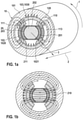
- a cross-section of a device 10 according to the invention is shown.
- the device 10 has a first field conducting element 101 in the form of a hollow cylinder.
- the first field conducting element 101 is preferably closed in the circumferential direction 1 .
- the first field conducting element 101 extends in the axial direction 2.
- the hollow-cylindrical field conducting element 101 is ring-shaped and extends in a closed manner in the circumferential direction 1.
- the first field conducting element 101 has a recess in the center that extends in the axial direction 2.
- the recess in the first field conducting element 101 is preferably cylindrical, so that the hollow-cylindrical first field conducting element 101 is hollow.
- the first field conducting element 101 has a wall thickness of 3 in the radial direction.
- the first field conducting element 101 is used to manage one Magnetic field 120.
- the magnetic field 120 is conducted essentially in the circumferential direction 1 in the wall of the first field conducting element 101. Essentially, this means that magnetic field 120 also has field components that do not point in circumferential direction 1, but rather in radial direction 3 and axial direction 2. However, magnetic field 120 is essentially directed in circumferential direction 1 within first field conducting element 101.
- the exciter magnets 110 are arranged within the first field conducting element 101 .
- the exciter magnets 110 are half-shell shaped and therefore have a trough shape.
- the excitation magnets 110 are in the form of segments of a circular ring and extend in the circumferential direction 1 and in the axial direction 2.
- the radially outer wall of the excitation magnet 110 is approximately parallel to the radially inward-facing wall of the first field conducting element 101.
- the excitation magnet 110 extends in the axial direction 2 along the first field conducting element 101.
- the field magnet 110 can be the same length or longer or shorter than the first field conducting element 1 with respect to the axial direction 2.
- the excitation magnets 110 are magnetized in the radial direction 3 .
- the excitation magnets 110 introduce their magnetic field 120 into the first field conducting element 101 .
- the excitation magnets 110 are arranged in the first field conducting element 101 in such a way that they can be moved in the circumferential direction 2 . This makes it possible for the exciter magnet 110 to move in the circumferential direction 1 on a circular path 111 .
- the exciter magnets 110 revolve around the axis of rotational symmetry of the first field conducting element 101.
- the exciter magnets 110 move on a circular path 111. It is particularly advantageous if the exciter magnets 110 and the first field conducting element 101 move together on the path 111.
- the exciter magnets 110 are in a fixed arrangement with the first field guide element 101 and preferably touch it with their radially outward-facing side, so that the wall on the outside of the exciter magnet 110 and the wall on the inside of the first flux guide element 101 touch in relation to the radial direction 2 . It is also conceivable that only the exciter magnets 110 move along the radially inner wall of the first field conducting element 101 .
- the excitation magnets 110 preferably comprise rare earth materials such as neodymium-iron-boron.
- the two excitation magnets 110 in the Figures 1a and 1b don't touch.
- the two field magnets 110 are spaced apart from one another in the circumferential direction 1 . This forms a gap 113 between the field magnets 110.
- the gap 113 is at the same location in the radial direction 3 as the field magnets 110.
- the gap 113 has the same location in the radial direction 3 Extension to that of the excitation magnets 110.
- the gap also extends in the axial direction 2 over the entire length of the excitation magnets 110.
- Two parts 1020 of a second field conducting element 102 are arranged in the first field conducting element 101 .
- the parts 1020 of the second field conducting element 102 are in the form of segments of a circular ring.
- the parts 1020 extend in the circumferential direction 1 and in the axial direction 2 as well as in the radial direction 3.
- the parts 1020 can be the same length or shorter or longer than the excitation magnets 110 or the first field conducting element 101.
- the parts 1020 of the second field conducting element 102 are arranged concentrically to the exciter magnet 110 and the first field conducting element 101 .
- the radially outer walls of the parts 1020 are arranged opposite the radially inner walls of the excitation magnets 110 and the first field conducting element 101 . The walls are almost parallel to each other.
- the field conducting elements 101, 102 are metallic and conduct magnetic fields 120.
- the magnetic field 120 which emanates from the exciter magnet 110, is conducted through the first field conducting element 101—as a type of magnetic return ring—and through the second field conducting element 102.
- the second field conducting element 102 is stationary.
- the first field conducting element 101 performs a circular movement together with the exciter magnet 110.
- the movable exciter magnets 110 are in Fig.1a positioned in a short-circuit position 211 . In the short-circuit position 211, the magnetic field flows through the first field conducting element 101 and the second field conducting element 102.
- the magnetic field 120 flows through the second field conducting element 102 and the first field conducting element 101 essentially in the circumferential direction 1.
- a third field conducting element 103 is arranged concentrically to the first field conducting element 101, the excitation magnet 110 and the second field conducting element 102, the third field conducting element 103 being cylindrical.
- the radially outer wall of the third field conducting element 103 is opposite the walls of the first and second field conducting elements 101 , 102 .
- the walls of the field conducting elements 101, 102, 103 are almost parallel to one another.
- the third field conducting element 103 serves as a receiving mandrel 1030 for a pole housing 202 of an electrical machine, with permanent magnets 201 being arranged inside the pole housing 202 .
- the permanent magnets 201 are attached to the inner wall of the pole housing 1030 .
- the permanent magnets 201 are fastened within the pole housing 202 by gluing or by mechanical fasteners, such as clasps or clips, which exert a spring force on the permanent magnets 201 so that they are pressed against the inner wall of the Pole housing 202 are pressed. These clasps, clips and the adhesive are not shown.
- the device 10 is suitable for magnetizing two-pole pole housings 202 . Therefore, two field magnets 110 and two parts 1020 of the second field conducting element 102 are arranged in the device 10 .
- a gap 203 is formed between the third field conducting element 103 and the second field conducting element 102 .
- the permanent magnets 201 together with the pole housing 202 are arranged in the gap 203 .
- the third field conducting element 103 is also stationary.
- the magnetic field 120 does not flow through the third field conducting element 103.
- the magnetic field 120 thus does not flow through the permanent magnets 201.
- the third field conducting element 103 can be removed from the device 10.
- the third field conducting element 103 can be fitted with the pole housing 202 containing permanent magnets 201 when it has been removed from the device 10 .
- the pole housing 202 with the permanent magnets 201 is pushed onto the third field conducting element 103, which serves as a holding mandrel 1030, so that the holding mandrel 1030 is arranged inside the pole housing 202.
- the permanent magnet 201 is arranged between the wall of the pole housing 202 and the wall of the receiving mandrel 1030 .
- the wall of the permanent magnet 201 and the wall of the receiving mandrel 1030 are almost parallel.
- the holding mandrel 1030 and the permanent magnets 201 preferably touch one another.
- the holding mandrel 1030 with the pole housing 202 with permanent magnets 201 placed on it is reinserted into the device 10 .
- the radially outer wall of the pole housing 202, which faces the parts 1020 of the second field conducting element 102, is approximately parallel to the wall of the parts 1020.
- the pole housing 202 and the parts 1020 of the second field conducting element 102 preferably touch the gap 203 as a receptacle 20 for the permanent magnets 201.
- the third field conducting element 103 cannot be removed from the device 10, so that the pole housing 202 with the permanent magnets 201 is inserted into the device 10 and thereby rests on the already previously arranged in the device 10 third field conducting element 103 is placed.
- Fig.1b the bipolar device 10 is off Fig. 1a shown.
- the exciter magnets 110 in Fig.1b are in magnetization position 210.
- an exciter magnet 110 is only directly opposite one of the parts 1020 of the second field conducting element 102, while in the short-circuit position 211 an exciter magnet 110 is directly opposite two parts 1020, so that the two exciter magnets 110 are connected by the two parts 120 are magnetically connected.
- the exciter magnets 110 shorted by parts 1020.
- the magnetic field lines 120 can flow from an exciter magnet 110 via part 1020 of the second field conducting element 102 to the opposite exciter magnet 110 without flowing through the permanent magnets 201 or the third field conducting element 103 .
- the magnetic field lines 120 extend on the one hand through the first field conducting element 101 and on the other hand through the second field conducting element 102, the permanent magnets 201 and the third field conducting element 103. A magnetic path is thus formed which leads through the permanent magnets 201.
- a cavity 1021 is arranged between the parts 1020 of the second field conducting element 102 .
- the cavity 1021 extends in the circumferential direction between two adjacent parts 1020.
- the cavity 1021 is at the same height as the parts 1020 in the radial direction 3.
- the cavity 1021 is bridged by an excitation magnet 110.
- the gap 113 between two excitation magnets 110 and the cavity 1021 are radially adjacent. Thus, the cavity 1021 is not bridged.
- Fig.2 a cross section of a further device 10 according to the invention is shown.
- the device 10 is shown as having a four-pole configuration. instead of as in Fig.1a,b to have two excitation magnets 110, the device in Fig.2 four excitation magnets 110 on.
- the excitation magnets 110 are magnetized in the radial direction 3 .
- Opposite exciter magnets 110 are each polarized in opposite directions, so that their magnetic field lines 120 repel each other while they extend in the radial direction 2 towards the center of the device 10 . With a polarity in the same direction, the field lines 120 flow from one exciter magnet 110 to the other and penetrate into it. However, it is also conceivable that the excitation magnets 110 are polarized in the same direction.
- the second field conducting element 102 has four parts 1020 .
- An auxiliary magnet 112 is arranged in the cavity 1021 .
- the auxiliary magnet 112 is stationary.
- the auxiliary magnet 112 comprises rare earth materials and is polarized in the circumferential direction 1 .
- the auxiliary magnet 112 can also be used with the two-pole device 10 Fig.1 come into use.
- the four-pole device 10 off Fig.2 is equipped with a pole housing 202, which has four permanent magnets 201.
- the permanent magnets 201 are as in Fig.1 arranged within the pole housing 202.
- Fig.3 shows a six-pole device 10.
- the device 10 has six exciter magnets 110, six parts 1020 of the second field conducting element 102 and six permanent magnets 201.
- Permanent magnets 201 for electrical machines can be magnetized with the devices 10 of the different exemplary embodiments. However, it is also conceivable to produce permanent magnets for other applications—except for electrical machines.
- the permanent magnets 201 consist of ferrite material. But it is also possible to use permanent magnets 201 made of rare earth materials.
- the field conducting elements 101, 102, 103 are preferably made of solid material. The material is not permanent magnetic, but magnetically conductive. It is conceivable that the field conducting elements 101, 102, 103 consist of electrical steel sheets.
- Such a field conducting element 101, 102, 103 constructed from electrical sheets has a laminated structure.
- the advantage of a laminated structure is given by the low magnetic loss scattering.
- the field conducting elements 101, 102, 103 are not permanently magnetic, but they conduct a magnetic flux well.
Landscapes
- Engineering & Computer Science (AREA)
- Power Engineering (AREA)
- Physics & Mathematics (AREA)
- Electromagnetism (AREA)
- Permanent Field Magnets Of Synchronous Machinery (AREA)
- External Artificial Organs (AREA)
- Magnetic Resonance Imaging Apparatus (AREA)
Claims (16)
- Dispositif (10) permettant de magnétiser au moins un aimant permanent (201), le dispositif (10) comprenant un premier élément conducteur de champ (101) et un deuxième élément conducteur de champ (102), plus d'un aimant d'excitation (110) étant disposé entre le premier et le deuxième élément conducteur de champ (101, 102), ledit plus d'un aimant d'excitation (110) étant magnétisé dans la direction radiale (3), le deuxième élément conducteur de champ (102) étant composé de pièces en forme de segments d'anneau de cercle (1020) qui ne se touchent pas et sont disposées de manière adjacente les unes aux autres par rapport à la direction circonférentielle (1), et le deuxième élément conducteur de champ (102) comprenant un logement (20) pour un aimant brut à magnétiser, ledit plus d'un aimant d'excitation (110) étant mobile par rapport aux éléments conducteurs de champ (101, 102) et à l'aimant brut (201) sur une trajectoire circulaire (111) autour de l'aimant brut de sorte que dans une position de magnétisation (210), un champ magnétique (120) de l'aimant d'excitation (110) magnétise l'aimant brut en aimant permanent.
- Dispositif (10) selon la revendication 1, caractérisé en ce que le premier élément conducteur de champ (101) est en forme de cylindre creux, et le deuxième élément conducteur de champ (102) est en forme de segment d'anneau de cercle dans la direction circonférentielle (1), le deuxième élément conducteur de champ étant disposé dans le premier élément conducteur de champ (101, 102) de sorte que les éléments conducteurs de champ (101, 102) sont disposés de manière concentrique l'un par rapport à l'autre, leurs parois radialement extérieures étant opposées au moins par endroits.
- Dispositif (10) selon la revendication 1 ou 2, caractérisé en ce que l'aimant d'excitation (110) est en forme de segment d'anneau de cercle et s'étend dans la direction axiale (2), les parois de l'aimant d'excitation (110) et du premier et deuxième élément conducteur de champ (101, 102) étant approximativement parallèles les unes aux autres.
- Dispositif (10) selon l'une quelconque des revendications précédentes, caractérisé en ce qu'un troisième élément conducteur de champ (103) est disposé à l'intérieur du deuxième élément conducteur de champ (102), le troisième élément conducteur de champ (103) étant cylindrique de sorte que le troisième élément conducteur de champ est disposé de manière concentrique par rapport au premier et au deuxième élément conducteur de champ (101, 102) de telle sorte que leurs parois sont opposées, entre le deuxième et le troisième élément conducteur de champ (102, 103) un entrefer (203) étant réalisé qui est un logement (20) pour l'aimant brut.
- Dispositif (10) selon l'une quelconque des revendications précédentes, caractérisé en ce que l'aimant d'excitation (110) est mobile dans la direction circonférentielle (1) de sorte que lors de son mouvement, l'aimant d'excitation (110) contourne le deuxième élément conducteur de champ (102) et est de préférence monté sur roulement à billes.
- Dispositif (10) selon l'une quelconque des revendications précédentes, caractérisé en ce que deux ou quatre ou six aimants d'excitation (110) sont disposés entre le premier et le deuxième élément conducteur de champ (101, 102), les aimants d'excitation (110) étant magnétisés dans la direction radiale (3).
- Dispositif (10) selon l'une quelconque des revendications précédentes, caractérisé en ce que le deuxième élément conducteur de champ (102) est composé de deux ou de quatre ou de six pièces (1020) en forme de segments d'anneau de cercle.
- Dispositif (10) selon l'une quelconque des revendications précédentes, caractérisé en ce qu'à la fois dans la direction circonférentielle (1) et dans la direction radiale (3), un aimant auxiliaire (112) est disposé entre deux pièces adjacentes (1020) du deuxième élément conducteur de champ (102), l'aimant auxiliaire (112) étant magnétisé tangentiellement par rapport à la direction circonférentielle (1).
- Dispositif (10) selon l'une quelconque des revendications précédentes, caractérisé en ce que le troisième élément conducteur de champ (103) sert de mandrin porte-pièce (1030) pour l'aimant brut à l'intérieur d'une carcasse polaire (202) d'une machine électrique de sorte que la carcasse polaire (202) repose sur le mandrin porte-pièce (1031), l'aimant brut étant disposé entre le mandrin porte-pièce (1031) et la carcasse polaire (202).
- Dispositif (10) selon l'une quelconque des revendications précédentes, caractérisé en ce que le troisième élément conducteur de champ (103) peut être retiré du deuxième élément conducteur de champ (102) dans la direction axiale (2).
- Procédé permettant de magnétiser des aimants permanents (201) au moyen d'un dispositif (10) selon la revendication 1, comprenant les étapes consistant à :- disposer l'aimant brut dans le logement (20),- déplacer relativement l'aimant d'excitation (110) dans la direction circonférentielle (1) sur une trajectoire circulaire (111) autour de l'aimant brut,- magnétiser l'aimant brut en aimant permanent (201),- retirer l'aimant permanent (201).
- Procédé selon la revendication 11, caractérisé en ce que le troisième élément conducteur de champ (103) est introduit avec l'aimant brut dans une carcasse polaire (202), et ensuite, le troisième élément conducteur de champ (103) avec la carcasse polaire (202) est disposé de manière concentrique dans le deuxième élément conducteur de champ (102).
- Procédé selon la revendication 11, caractérisé en ce que d'abord le troisième élément conducteur de champ (103) est disposé dans le deuxième élément conducteur de champ (102), et la carcasse polaire (202) est ensuite emmanchée axialement avec l'aimant brut à l'intérieur du deuxième élément conducteur de champ (102) sur le troisième élément conducteur de champ (103) .
- Procédé selon l'une quelconque des revendications précédentes, caractérisé en ce que l'aimant d'excitation (110) effectue un mouvement dans la direction circonférentielle (1) autour du deuxième élément conducteur de champ (102) jusqu'à ce que l'aimant d'excitation (110) soit positionné dans la position de magnétisation (210), le champ magnétique (120) dans la position de magnétisation (210) traversant les éléments conducteurs de champ (101, 102, 103) et l'aimant brut et magnétisant ainsi l'aimant brut en aimant permanent (201).
- Procédé selon l'une quelconque des revendications précédentes, caractérisé en ce que l'aimant d'excitation (110) effectue un mouvement jusqu'à ce qu'il se trouve dans une position de court-circuit (211) dans laquelle le champ magnétique (120) traverse le premier et le deuxième élément conducteur de champ (101, 103) mais pas le troisième élément conducteur de champ (103) et l'aimant permanent (201).
- Procédé selon l'une quelconque des revendications précédentes, caractérisé en ce que l'aimant permanent (201) est retiré du et/ou inséré dans le dispositif (10) lorsque l'aimant d'excitation (110) se trouve dans la position de court-circuit (211).
Priority Applications (1)
| Application Number | Priority Date | Filing Date | Title |
|---|---|---|---|
| RS20220333A RS63092B1 (sr) | 2014-12-15 | 2015-10-19 | Uređaj i postupak za magnetisanje stalnih magneta |
Applications Claiming Priority (2)
| Application Number | Priority Date | Filing Date | Title |
|---|---|---|---|
| DE102014225900.2A DE102014225900A1 (de) | 2014-12-15 | 2014-12-15 | Vorrichtung und Verfahren zum Magnetisieren von Permanentmagneten |
| PCT/EP2015/074076 WO2016096190A1 (fr) | 2014-12-15 | 2015-10-19 | Dispositif et procédé de magnétisation d'aimants permanents |
Publications (2)
| Publication Number | Publication Date |
|---|---|
| EP3234967A1 EP3234967A1 (fr) | 2017-10-25 |
| EP3234967B1 true EP3234967B1 (fr) | 2022-02-16 |
Family
ID=54330763
Family Applications (1)
| Application Number | Title | Priority Date | Filing Date |
|---|---|---|---|
| EP15781646.3A Active EP3234967B1 (fr) | 2014-12-15 | 2015-10-19 | Dispositif et procédé de magnétisation d'aimants permanents |
Country Status (6)
| Country | Link |
|---|---|
| EP (1) | EP3234967B1 (fr) |
| KR (1) | KR20170094219A (fr) |
| CN (1) | CN107004490B (fr) |
| DE (1) | DE102014225900A1 (fr) |
| RS (1) | RS63092B1 (fr) |
| WO (1) | WO2016096190A1 (fr) |
Families Citing this family (8)
| Publication number | Priority date | Publication date | Assignee | Title |
|---|---|---|---|---|
| EP3270389B1 (fr) * | 2016-07-12 | 2019-04-10 | Ncte Ag | Magnetisation d'arbre creux |
| ES2848830T3 (es) | 2017-04-27 | 2021-08-12 | Bard Access Systems Inc | Sistema de guiado para guiar la inserción de una aguja en el cuerpo de un paciente que comprende un sistema de magnetización para conjuntos de agujas |
| CN110277214B (zh) * | 2019-07-26 | 2024-12-10 | 宁波尼兰德磁业股份有限公司 | 超高用磁场磁回路 |
| EP3799086B1 (fr) | 2019-09-25 | 2024-03-27 | Grundfos Holding A/S | Dispositif de magnétisation basé sur un aimant permanent |
| CN216417315U (zh) | 2020-11-09 | 2022-05-03 | 巴德阿克塞斯系统股份有限公司 | 磁化器及相关系统 |
| US12059243B2 (en) | 2020-11-10 | 2024-08-13 | Bard Access Systems, Inc. | Sterile cover for medical devices and methods thereof |
| CN217982371U (zh) | 2021-06-22 | 2022-12-06 | 巴德阿克塞斯系统股份有限公司 | 与包括含铁元件的医疗设备一起使用的磁化器系统 |
| US12230427B2 (en) | 2021-07-26 | 2025-02-18 | Bard Access Systems, Inc. | Medical-device magnetizer systems and methods |
Family Cites Families (6)
| Publication number | Priority date | Publication date | Assignee | Title |
|---|---|---|---|---|
| JPH02155450A (ja) * | 1988-12-05 | 1990-06-14 | Tdk Corp | 小型モーター組立用着磁装置 |
| JP3474152B2 (ja) * | 2000-08-10 | 2003-12-08 | 三菱電機株式会社 | 永久磁石回転子の着磁装置 |
| JP2002199669A (ja) * | 2000-12-22 | 2002-07-12 | Hitachi Ltd | 永久磁石の着磁方法 |
| CN2598108Y (zh) * | 2002-11-26 | 2004-01-07 | 刘吉科 | 电动旋转磁化器 |
| KR101407837B1 (ko) * | 2010-04-05 | 2014-06-16 | 아이치 세이코우 가부시키가이샤 | 이방성 본드 자석의 제조 방법 및 그 제조 장치 |
| DE102011105324A1 (de) * | 2011-06-03 | 2012-12-06 | Minebea Co., Ltd. | Spritzgusswerkzeug |
-
2014
- 2014-12-15 DE DE102014225900.2A patent/DE102014225900A1/de active Pending
-
2015
- 2015-10-19 WO PCT/EP2015/074076 patent/WO2016096190A1/fr not_active Ceased
- 2015-10-19 CN CN201580068194.1A patent/CN107004490B/zh active Active
- 2015-10-19 RS RS20220333A patent/RS63092B1/sr unknown
- 2015-10-19 KR KR1020177016237A patent/KR20170094219A/ko not_active Withdrawn
- 2015-10-19 EP EP15781646.3A patent/EP3234967B1/fr active Active
Also Published As
| Publication number | Publication date |
|---|---|
| CN107004490A (zh) | 2017-08-01 |
| RS63092B1 (sr) | 2022-04-29 |
| WO2016096190A1 (fr) | 2016-06-23 |
| EP3234967A1 (fr) | 2017-10-25 |
| CN107004490B (zh) | 2019-12-20 |
| KR20170094219A (ko) | 2017-08-17 |
| DE102014225900A1 (de) | 2016-06-16 |
Similar Documents
| Publication | Publication Date | Title |
|---|---|---|
| EP3234967B1 (fr) | Dispositif et procédé de magnétisation d'aimants permanents | |
| EP1843454B1 (fr) | Unité d'engrenage et support d'outil doté d'une telle unité d'engrenage | |
| DE102011105867B4 (de) | Rotor für eine elektrische Maschine | |
| DE102015121102B4 (de) | Rotorvorrichtung für einen Elektromotor und/oder Generator, Rotor und Motor mit einer solchen Rotorvorrichtung sowie Herstellungsverfahren | |
| DE102015111480A1 (de) | Rotor und elektrische Maschine | |
| DE102011075548A1 (de) | Lager mit einer Energieerfassungseinheit, insbesondere Pendelrollen-Lager zur Lagerung einer Walze | |
| DE102009031609A1 (de) | Lager mit Energieerzeugungseinheit | |
| EP2374199B1 (fr) | Machine électrique avec rotor | |
| DE102014115563A1 (de) | Rotor und Motor | |
| DE1538992C3 (de) | Gleichstrommotor mit einem zylindrischen Rotor und einem einzigen Permanentmagneten im Stator | |
| DE2906795A1 (de) | Impulsgeber | |
| DE2650510B2 (de) | Gleichstrommotor | |
| DE102016214838A1 (de) | Ermitteln einer Drehrichtung eines Läufers einer rotierenden elektrischen Maschine | |
| DE202020104661U1 (de) | Motor zur Verwendung in einem externen Magnetfeld | |
| EP3560084A1 (fr) | Procédé de fabrication et procédé de démontage d'une machine électrique tournante à excitation permanente | |
| DE10247228B4 (de) | Verfahren und Vorrichtung zum Magnetisieren eines dauermagnetischen Ringmagneten mit gerader Polzahl | |
| DE4417903C2 (de) | Aufmagnetisierungsvorrichtung für elektrische Maschinen mit Dauermagnetläufer | |
| WO2021037301A1 (fr) | Élément actif d'une machine électrique, machine électrique et procédé de fabrication d'un module préassemblé pour l'élément actif | |
| DE102016212328A1 (de) | Rotoranordnung einer elektrischen Maschine | |
| DE202019103225U1 (de) | Drehmomentoptimierter mehrpoliger Rotor für einen Elektromotor | |
| DE102018121062A1 (de) | Verfahren und Vorrichtung zum Herstellen eines Speichenrotors für eine elektrische Maschine | |
| DE10055079C1 (de) | Verfahren zur Herstellung eines Stators für eine elektrische Linearmaschine | |
| DE1009277B (de) | Magnetelektrischer Wechselstromerzeuger | |
| DE10055080A1 (de) | Elektrische Linearmaschine | |
| WO2014060228A2 (fr) | Ensemble stator pour une machine électrique à excitation par aimants permanents |
Legal Events
| Date | Code | Title | Description |
|---|---|---|---|
| STAA | Information on the status of an ep patent application or granted ep patent |
Free format text: STATUS: THE INTERNATIONAL PUBLICATION HAS BEEN MADE |
|
| PUAI | Public reference made under article 153(3) epc to a published international application that has entered the european phase |
Free format text: ORIGINAL CODE: 0009012 |
|
| STAA | Information on the status of an ep patent application or granted ep patent |
Free format text: STATUS: REQUEST FOR EXAMINATION WAS MADE |
|
| 17P | Request for examination filed |
Effective date: 20170717 |
|
| AK | Designated contracting states |
Kind code of ref document: A1 Designated state(s): AL AT BE BG CH CY CZ DE DK EE ES FI FR GB GR HR HU IE IS IT LI LT LU LV MC MK MT NL NO PL PT RO RS SE SI SK SM TR |
|
| AX | Request for extension of the european patent |
Extension state: BA ME |
|
| DAV | Request for validation of the european patent (deleted) | ||
| DAX | Request for extension of the european patent (deleted) | ||
| STAA | Information on the status of an ep patent application or granted ep patent |
Free format text: STATUS: EXAMINATION IS IN PROGRESS |
|
| 17Q | First examination report despatched |
Effective date: 20190625 |
|
| RAP1 | Party data changed (applicant data changed or rights of an application transferred) |
Owner name: ROBERT BOSCH GMBH |
|
| GRAP | Despatch of communication of intention to grant a patent |
Free format text: ORIGINAL CODE: EPIDOSNIGR1 |
|
| STAA | Information on the status of an ep patent application or granted ep patent |
Free format text: STATUS: GRANT OF PATENT IS INTENDED |
|
| INTG | Intention to grant announced |
Effective date: 20211005 |
|
| RIN1 | Information on inventor provided before grant (corrected) |
Inventor name: BUEYUEKASIK, DIYAP |
|
| GRAS | Grant fee paid |
Free format text: ORIGINAL CODE: EPIDOSNIGR3 |
|
| GRAA | (expected) grant |
Free format text: ORIGINAL CODE: 0009210 |
|
| STAA | Information on the status of an ep patent application or granted ep patent |
Free format text: STATUS: THE PATENT HAS BEEN GRANTED |
|
| AK | Designated contracting states |
Kind code of ref document: B1 Designated state(s): AL AT BE BG CH CY CZ DE DK EE ES FI FR GB GR HR HU IE IS IT LI LT LU LV MC MK MT NL NO PL PT RO RS SE SI SK SM TR |
|
| REG | Reference to a national code |
Ref country code: GB Ref legal event code: FG4D Free format text: NOT ENGLISH |
|
| REG | Reference to a national code |
Ref country code: CH Ref legal event code: EP |
|
| REG | Reference to a national code |
Ref country code: DE Ref legal event code: R096 Ref document number: 502015015640 Country of ref document: DE |
|
| REG | Reference to a national code |
Ref country code: AT Ref legal event code: REF Ref document number: 1469401 Country of ref document: AT Kind code of ref document: T Effective date: 20220315 |
|
| REG | Reference to a national code |
Ref country code: IE Ref legal event code: FG4D Free format text: LANGUAGE OF EP DOCUMENT: GERMAN |
|
| REG | Reference to a national code |
Ref country code: LT Ref legal event code: MG9D |
|
| REG | Reference to a national code |
Ref country code: NL Ref legal event code: MP Effective date: 20220216 |
|
| PG25 | Lapsed in a contracting state [announced via postgrant information from national office to epo] |
Ref country code: SE Free format text: LAPSE BECAUSE OF FAILURE TO SUBMIT A TRANSLATION OF THE DESCRIPTION OR TO PAY THE FEE WITHIN THE PRESCRIBED TIME-LIMIT Effective date: 20220216 Ref country code: PT Free format text: LAPSE BECAUSE OF FAILURE TO SUBMIT A TRANSLATION OF THE DESCRIPTION OR TO PAY THE FEE WITHIN THE PRESCRIBED TIME-LIMIT Effective date: 20220616 Ref country code: NO Free format text: LAPSE BECAUSE OF FAILURE TO SUBMIT A TRANSLATION OF THE DESCRIPTION OR TO PAY THE FEE WITHIN THE PRESCRIBED TIME-LIMIT Effective date: 20220516 Ref country code: NL Free format text: LAPSE BECAUSE OF FAILURE TO SUBMIT A TRANSLATION OF THE DESCRIPTION OR TO PAY THE FEE WITHIN THE PRESCRIBED TIME-LIMIT Effective date: 20220216 Ref country code: LT Free format text: LAPSE BECAUSE OF FAILURE TO SUBMIT A TRANSLATION OF THE DESCRIPTION OR TO PAY THE FEE WITHIN THE PRESCRIBED TIME-LIMIT Effective date: 20220216 Ref country code: HR Free format text: LAPSE BECAUSE OF FAILURE TO SUBMIT A TRANSLATION OF THE DESCRIPTION OR TO PAY THE FEE WITHIN THE PRESCRIBED TIME-LIMIT Effective date: 20220216 Ref country code: ES Free format text: LAPSE BECAUSE OF FAILURE TO SUBMIT A TRANSLATION OF THE DESCRIPTION OR TO PAY THE FEE WITHIN THE PRESCRIBED TIME-LIMIT Effective date: 20220216 Ref country code: BG Free format text: LAPSE BECAUSE OF FAILURE TO SUBMIT A TRANSLATION OF THE DESCRIPTION OR TO PAY THE FEE WITHIN THE PRESCRIBED TIME-LIMIT Effective date: 20220516 |
|
| REG | Reference to a national code |
Ref country code: HU Ref legal event code: AG4A Ref document number: E058363 Country of ref document: HU |
|
| PG25 | Lapsed in a contracting state [announced via postgrant information from national office to epo] |
Ref country code: PL Free format text: LAPSE BECAUSE OF FAILURE TO SUBMIT A TRANSLATION OF THE DESCRIPTION OR TO PAY THE FEE WITHIN THE PRESCRIBED TIME-LIMIT Effective date: 20220216 Ref country code: LV Free format text: LAPSE BECAUSE OF FAILURE TO SUBMIT A TRANSLATION OF THE DESCRIPTION OR TO PAY THE FEE WITHIN THE PRESCRIBED TIME-LIMIT Effective date: 20220216 Ref country code: GR Free format text: LAPSE BECAUSE OF FAILURE TO SUBMIT A TRANSLATION OF THE DESCRIPTION OR TO PAY THE FEE WITHIN THE PRESCRIBED TIME-LIMIT Effective date: 20220517 Ref country code: FI Free format text: LAPSE BECAUSE OF FAILURE TO SUBMIT A TRANSLATION OF THE DESCRIPTION OR TO PAY THE FEE WITHIN THE PRESCRIBED TIME-LIMIT Effective date: 20220216 |
|
| PG25 | Lapsed in a contracting state [announced via postgrant information from national office to epo] |
Ref country code: IS Free format text: LAPSE BECAUSE OF FAILURE TO SUBMIT A TRANSLATION OF THE DESCRIPTION OR TO PAY THE FEE WITHIN THE PRESCRIBED TIME-LIMIT Effective date: 20220617 |
|
| PG25 | Lapsed in a contracting state [announced via postgrant information from national office to epo] |
Ref country code: SM Free format text: LAPSE BECAUSE OF FAILURE TO SUBMIT A TRANSLATION OF THE DESCRIPTION OR TO PAY THE FEE WITHIN THE PRESCRIBED TIME-LIMIT Effective date: 20220216 Ref country code: SK Free format text: LAPSE BECAUSE OF FAILURE TO SUBMIT A TRANSLATION OF THE DESCRIPTION OR TO PAY THE FEE WITHIN THE PRESCRIBED TIME-LIMIT Effective date: 20220216 Ref country code: RO Free format text: LAPSE BECAUSE OF FAILURE TO SUBMIT A TRANSLATION OF THE DESCRIPTION OR TO PAY THE FEE WITHIN THE PRESCRIBED TIME-LIMIT Effective date: 20220216 Ref country code: EE Free format text: LAPSE BECAUSE OF FAILURE TO SUBMIT A TRANSLATION OF THE DESCRIPTION OR TO PAY THE FEE WITHIN THE PRESCRIBED TIME-LIMIT Effective date: 20220216 Ref country code: DK Free format text: LAPSE BECAUSE OF FAILURE TO SUBMIT A TRANSLATION OF THE DESCRIPTION OR TO PAY THE FEE WITHIN THE PRESCRIBED TIME-LIMIT Effective date: 20220216 Ref country code: CZ Free format text: LAPSE BECAUSE OF FAILURE TO SUBMIT A TRANSLATION OF THE DESCRIPTION OR TO PAY THE FEE WITHIN THE PRESCRIBED TIME-LIMIT Effective date: 20220216 |
|
| REG | Reference to a national code |
Ref country code: DE Ref legal event code: R097 Ref document number: 502015015640 Country of ref document: DE |
|
| PG25 | Lapsed in a contracting state [announced via postgrant information from national office to epo] |
Ref country code: AL Free format text: LAPSE BECAUSE OF FAILURE TO SUBMIT A TRANSLATION OF THE DESCRIPTION OR TO PAY THE FEE WITHIN THE PRESCRIBED TIME-LIMIT Effective date: 20220216 |
|
| PLBE | No opposition filed within time limit |
Free format text: ORIGINAL CODE: 0009261 |
|
| STAA | Information on the status of an ep patent application or granted ep patent |
Free format text: STATUS: NO OPPOSITION FILED WITHIN TIME LIMIT |
|
| 26N | No opposition filed |
Effective date: 20221117 |
|
| PG25 | Lapsed in a contracting state [announced via postgrant information from national office to epo] |
Ref country code: SI Free format text: LAPSE BECAUSE OF FAILURE TO SUBMIT A TRANSLATION OF THE DESCRIPTION OR TO PAY THE FEE WITHIN THE PRESCRIBED TIME-LIMIT Effective date: 20220216 |
|
| PG25 | Lapsed in a contracting state [announced via postgrant information from national office to epo] |
Ref country code: MC Free format text: LAPSE BECAUSE OF FAILURE TO SUBMIT A TRANSLATION OF THE DESCRIPTION OR TO PAY THE FEE WITHIN THE PRESCRIBED TIME-LIMIT Effective date: 20220216 |
|
| REG | Reference to a national code |
Ref country code: CH Ref legal event code: PL |
|
| REG | Reference to a national code |
Ref country code: BE Ref legal event code: MM Effective date: 20221031 |
|
| GBPC | Gb: european patent ceased through non-payment of renewal fee |
Effective date: 20221019 |
|
| PG25 | Lapsed in a contracting state [announced via postgrant information from national office to epo] |
Ref country code: LU Free format text: LAPSE BECAUSE OF NON-PAYMENT OF DUE FEES Effective date: 20221019 |
|
| PG25 | Lapsed in a contracting state [announced via postgrant information from national office to epo] |
Ref country code: LI Free format text: LAPSE BECAUSE OF NON-PAYMENT OF DUE FEES Effective date: 20221031 Ref country code: IT Free format text: LAPSE BECAUSE OF FAILURE TO SUBMIT A TRANSLATION OF THE DESCRIPTION OR TO PAY THE FEE WITHIN THE PRESCRIBED TIME-LIMIT Effective date: 20220216 Ref country code: CH Free format text: LAPSE BECAUSE OF NON-PAYMENT OF DUE FEES Effective date: 20221031 |
|
| PG25 | Lapsed in a contracting state [announced via postgrant information from national office to epo] |
Ref country code: BE Free format text: LAPSE BECAUSE OF NON-PAYMENT OF DUE FEES Effective date: 20221031 |
|
| PG25 | Lapsed in a contracting state [announced via postgrant information from national office to epo] |
Ref country code: IE Free format text: LAPSE BECAUSE OF NON-PAYMENT OF DUE FEES Effective date: 20221019 Ref country code: GB Free format text: LAPSE BECAUSE OF NON-PAYMENT OF DUE FEES Effective date: 20221019 |
|
| REG | Reference to a national code |
Ref country code: AT Ref legal event code: MM01 Ref document number: 1469401 Country of ref document: AT Kind code of ref document: T Effective date: 20221019 |
|
| PG25 | Lapsed in a contracting state [announced via postgrant information from national office to epo] |
Ref country code: AT Free format text: LAPSE BECAUSE OF NON-PAYMENT OF DUE FEES Effective date: 20221019 |
|
| PG25 | Lapsed in a contracting state [announced via postgrant information from national office to epo] |
Ref country code: CY Free format text: LAPSE BECAUSE OF FAILURE TO SUBMIT A TRANSLATION OF THE DESCRIPTION OR TO PAY THE FEE WITHIN THE PRESCRIBED TIME-LIMIT Effective date: 20220216 |
|
| PG25 | Lapsed in a contracting state [announced via postgrant information from national office to epo] |
Ref country code: MK Free format text: LAPSE BECAUSE OF FAILURE TO SUBMIT A TRANSLATION OF THE DESCRIPTION OR TO PAY THE FEE WITHIN THE PRESCRIBED TIME-LIMIT Effective date: 20220216 |
|
| PG25 | Lapsed in a contracting state [announced via postgrant information from national office to epo] |
Ref country code: MT Free format text: LAPSE BECAUSE OF FAILURE TO SUBMIT A TRANSLATION OF THE DESCRIPTION OR TO PAY THE FEE WITHIN THE PRESCRIBED TIME-LIMIT Effective date: 20220216 |
|
| PGFP | Annual fee paid to national office [announced via postgrant information from national office to epo] |
Ref country code: HU Payment date: 20251016 Year of fee payment: 11 |
|
| PG25 | Lapsed in a contracting state [announced via postgrant information from national office to epo] |
Ref country code: TR Free format text: LAPSE BECAUSE OF FAILURE TO SUBMIT A TRANSLATION OF THE DESCRIPTION OR TO PAY THE FEE WITHIN THE PRESCRIBED TIME-LIMIT Effective date: 20220216 |
|
| PGFP | Annual fee paid to national office [announced via postgrant information from national office to epo] |
Ref country code: DE Payment date: 20251209 Year of fee payment: 11 |
|
| PGFP | Annual fee paid to national office [announced via postgrant information from national office to epo] |
Ref country code: FR Payment date: 20251029 Year of fee payment: 11 |
|
| PGFP | Annual fee paid to national office [announced via postgrant information from national office to epo] |
Ref country code: RS Payment date: 20251007 Year of fee payment: 11 |