EP3235579B2 - Strangführungseinrichtung und verfahren zum stützen eines giessstrangs - Google Patents
Strangführungseinrichtung und verfahren zum stützen eines giessstrangs Download PDFInfo
- Publication number
- EP3235579B2 EP3235579B2 EP17163459.5A EP17163459A EP3235579B2 EP 3235579 B2 EP3235579 B2 EP 3235579B2 EP 17163459 A EP17163459 A EP 17163459A EP 3235579 B2 EP3235579 B2 EP 3235579B2
- Authority
- EP
- European Patent Office
- Prior art keywords
- strand
- guide roller
- outer contour
- guide
- cast
- Prior art date
- Legal status (The legal status is an assumption and is not a legal conclusion. Google has not performed a legal analysis and makes no representation as to the accuracy of the status listed.)
- Active
Links
Images




Classifications
-
- B—PERFORMING OPERATIONS; TRANSPORTING
- B22—CASTING; POWDER METALLURGY
- B22D—CASTING OF METALS; CASTING OF OTHER SUBSTANCES BY THE SAME PROCESSES OR DEVICES
- B22D11/00—Continuous casting of metals, i.e. casting in indefinite lengths
- B22D11/12—Accessories for subsequent treating or working cast stock in situ
- B22D11/128—Accessories for subsequent treating or working cast stock in situ for removing
- B22D11/1287—Rolls; Lubricating, cooling or heating rolls while in use
-
- B—PERFORMING OPERATIONS; TRANSPORTING
- B22—CASTING; POWDER METALLURGY
- B22D—CASTING OF METALS; CASTING OF OTHER SUBSTANCES BY THE SAME PROCESSES OR DEVICES
- B22D11/00—Continuous casting of metals, i.e. casting in indefinite lengths
- B22D11/12—Accessories for subsequent treating or working cast stock in situ
- B22D11/128—Accessories for subsequent treating or working cast stock in situ for removing
Definitions
- the invention relates to a method for supporting a cast strand with a rectangular cross-section according to claim 1.
- strand guiding devices are known in the continuous casting of slabs with a rectangular cross section, in which guide rollers, so-called foot rollers, with a cylindrical outer contour for strand support on the narrow side of the strand shell box are used.
- a guide roller which has a cylindrical outer contour
- such cylindrical foot rollers can be used to guide or hold the strand shell box in a rectangular shape.
- the cast strand tends to bulge again due to the ferrostatic internal pressure of the liquid steel and the creep processes occurring within the strand shell.
- the slab produced deviates from the desired cross section.
- a cast strand is a
- DE 195 20 939 C1 shows a strand guiding device with the features of the preamble of claim 1 or of claim 3.
- carriers are provided on the outlet side of the continuous casting mold, on which rollers for guiding the strand are arranged.
- the carrier In order to adapt to a changing shrinkage of the strand, it is provided that the carrier, and thus the rollers attached thereto, can be adjusted transversely to the direction in which the strand is drawn off.
- the individual rollers which are rotatably mounted on the respective brackets, each have a cylindrical cross section, and thus suffer from the disadvantages mentioned above.
- the object of the invention is to use simple means to optimize the desired shape accuracy of a cast strand during continuous casting.
- a strand guide device is used to support a cast strand with a rectangular cross section, namely when the cast strand emerges from the continuous casting mold in a transport or withdrawal direction.
- the strand guide device comprises at least one guide roller, which is rotatably mounted about an axis of rotation, wherein the guide roller can be brought into contact with the cast strand with its outer contour running in the direction of the axis of rotation, in order to suitably guide and support the cast strand.
- the outer contour of the guide roller is convex and designed in such a way that its longitudinal extension along the axis of rotation is adapted to a narrow side of the rectangular cast strand.
- the convex outer contour of the guide roller is crowned, with the convex, outwardly curved curve of the guide roller beginning directly at the end faces of the guide roller and running in the direction of the central area of the guide roller.
- the strand guide device comprises at least one guide roller, which is rotatably mounted about an axis of rotation, wherein the guide roller can be brought into contact with the cast strand with its outer contour running in the direction of the axis of rotation, in order to suitably guide and support the cast strand.
- the outer contour of the guide roller is spherically convex, with the largest diameter of the outer contour of the guide roller in comparison to a diameter of the guide roller at the roller ends, ie on its end face, having a maximum value of 1.5 and a minimum value of 1.0.
- Such a guide roller can be provided to be employed either against the narrow side of a cast strand or against the longitudinal side of a cast strand.
- the outer contour of the guide roller is designed in such a way that its longitudinal extension along the axis of rotation is adapted to a narrow side of the rectangular cast strand.
- At least one rotatably mounted guide roller has a crowned, convex outer contour, the outer contour of the guide roller being formed by a continuous, convex, outwardly curved curve without a point of inflection, consisting of one or more radii, and the guide roller with this outer contour is placed against one side of the cast strand, while the cast strand still has elastic properties in an area near the edge, with the largest diameter (D_max) of the outer contour of the guide roller compared to a diameter (D_min) of the guide roller on its front side in the ratio assumes a maximum value of 1.5 and a minimum value of 1.0, and that in the transport direction (T) of the cast strand, a plurality of guide rollers are provided in alignment one behind the other and are jointly set against one side of the rectangular cast strand, with the individual guide rollers - downstream of the transport direction (T) of the cast strand - the crowning of the outer
- the invention is based on the essential finding that the strand shell of the cast strand, as long as it still has elastic properties in an area near the edge immediately after leaving the continuous casting mold, through contact with the guide rollers, which, as explained, have a crowned convex outer contour targeted concave shape is imposed, which counteracts the tendency of the strand shell to bulge.
- the measure of the crowning of the outer contour of a guide roller is suitably matched to the respective manufacturing parameters and the steel grade produced. This means that the crowning of the outer contour, which is determined by the ratio of the largest diameter of the roller surface to the diameter at the roller ends of the guide roller, is only selected to be large enough to compensate for the tendency of the strand shell to bulge .
- the contact of the strand shell of the cast strand with a guide roller of the strand guide device should not result in permanent deformation of the cast strand at the point of contact with the guide roller. This is ensured by the fact that the guide roller of the strand guide device is brought into contact with the cast strand at a time when the cast strand still has elastic properties.
- the crowned, convex outer contour of a guide roller is optimized for the individual problem that arises for a specific type of steel and its manufacturing parameters.
- the crowned, convex outer contour of a guide roller can be designed differently to adapt to the individual case, with the ratio of the largest diameter of the roller surface to the diameter of the roller surface at the roller ends, i.e. on a front side of the guide roller, being in the range between 1.5 and 1. 0 moves.
- the outer contour of the guide roller can be suitably adapted to the respective application.
- the bulging of the cast strand or a slab can be compensated for without excessive edge effects.
- the extent to which the outer contour of a guide roller is of convex crowned design is offset by the tendency of the strand shell of the cast strand to bulge to zero.
- a desired uniform rectangular shape is formed for the strand shell in cross section.
- the at least one guide roller of the strand guide device is rotatably accommodated in a cage mount.
- a cage mount is characterized by a robust and inexpensive construction and ensures a secure rotational mount for the guide roller, also taking into account the considerable forces that act on the guide roller during continuous casting.
- each guide roller is provided, each with a crowned, convex outer contour, with at least one guide roller being set against the narrow side of a cast strand, and with at least one further guide roller being set against the long side of the cast strand.
- the tendency of the strand shell of a cast strand to bulge is counteracted in that a plurality of guide rollers are provided, namely aligned one behind the other in the transport direction of the cast strand. All of these guide rollers are expediently accommodated in a rotatably mounted manner together in a cage mount of the strand guide device.
- the guide rollers which are arranged in alignment one behind the other, are each provided with a different crowned, convex outer contour.
- the quotient formed from the largest diameter of the outer contour or the roller surface to the diameter of the guide roller on its front side is greater than in the Compared to a guide roller which - seen in the transport direction of the cast strand - is closer to the continuous casting mold.
- a gentle support for the strand shell of the cast strand is achieved by the plurality of guide rollers with a crown which increases in the transport direction of the cast strand, in order to counteract the undesirable bulging of the strand shell at the same time.
- a connecting device is provided with which the strand guiding device can be positively attached to a continuous casting mold or adjacent thereto.
- the guide rollers are subject to pronounced wear during continuous casting.
- the connection device makes it possible to dismantle the strand guide device from the continuous casting mold if necessary and to replace it with a new strand guide device.
- a lifting device can be provided for the strand guide device, by means of which the strand guide device can be lifted upwards in the vertical direction.
- Such a lifting device can be in the form of a ring eye which can be fastened, for example, to an upper side of the cage holder, for example by means of a screw connection.
- the strand guide device By equipping the strand guide device with the connection device mentioned, it is thus possible to provide an exchangeable roller unit for continuous casting, which can be exchanged in a short time if required—either in the event of wear or to adapt to special types of steel.
- the strand guide device can be lifted vertically upwards out of the continuous casting mold by a crane or the like by means of the lifting device.
- the strand guiding device also comprises an elongated copper plate which—seen in the direction of transport of the cast strand—is provided upstream of the guide roller(s).
- the copper plate can expediently be attached to the mentioned cage holder.
- the cage mount, in which at least one guide roller is rotatably mounted, and the copper plate attached to it form an advantageous exchange module that can be quickly dismantled from the continuous casting mold and can therefore be exchanged.
- a strand guide device 10 for guiding and supporting a cast strand 12 is described, the strand guide device 10 having at least one rotatably mounted guide roller 14 for this purpose.
- FIGS. 1a, 1b and 1c are each shown different embodiments for a guide roller 14 in cross section.
- the guide rollers 14 are each mounted so as to be rotatable about an axis of rotation 16 and have an outer contour 18 which runs in the longitudinal extension along the axis of rotation 16 and is of crowned, convex design.
- a maximum diameter D_max of a guide roller 14 which is present approximately in a central area 20 thereof, is greater than a minimum diameter D_min of the guide roller, which is present at one end of the roller or at an end face 19 of the guide roller 14 .
- the design of the crowned, convex outer contour 18 of a guide roller 14 is selected in such a way that the ratio of the maximum diameter D_max of the roller surface to the minimum diameter at a roller end or at a front side of the guide roller 14 satisfies the condition: 1.5 ⁇ D_max / D_min ⁇ 1.0 .
- the diameter of the outer contour 18 of the guide roller 14 increases, starting from the end face 19 in the direction of the central area 20 up to a turning point W, with the increase or growth of the diameter decreasing again from this turning point until the central area 20 is reached.
- the curved course of the outer contour 18 up to the turning point W, starting from the end face 19, is defined by a first radius R1, the curved course of the outer contour 18 between the turning point W and the central area 20 being defined by a second radius R2.
- the first and second radius R1, R2 can each have a value of 1 mm or more, as a result of which "soft" curves are ensured for the outer contour 18.
- the radii R1, R2 and the turning point W are shown only for the area of the guide roller 14 to the left of the center. It goes without saying that the guide roller 14 is preferably formed symmetrically with respect to its center, so that the radii R1, R2 and the turning point W for the outer contour 18 are also provided in the area to the right of the center.
- FIG. 1b Another feature of the embodiment according to Fig. 1b is that the central region 20 of the outer contour 18 of the guide roller 14 has a constant diameter and is therefore of cylindrical design.
- the embodiment 1c is characterized in that its outer contour 18 is formed by a continuous convex outwardly curved curve without a point of inflection, it being possible for this curve to have one or more radii.
- This outwardly curved curve can have a predetermined distance from the end face 19 of the guide roller 14, with the representation according to FIG 1c this predetermined distance has the value zero.
- the convex outwardly curved curve directly at the end faces 19 of the guide roller 14, and then runs in the direction of the central region 20.
- the predetermined distance from the end face 19 at which the outwardly curved curve for the outer contour 18 begins has a value of up to 50 mm.
- a guide roller 14 of the strand guide device 10 serves the purpose of being set against a strand shell box 21 of the cast strand 12 .
- FIGs 1a, 1b and 1c It is illustrated in each case that a guide roller 14 is pressed or employed against a narrow side 22 of the cast strand 12, which has a rectangular cross section. It can be seen that a length of the guide roller 14 along its axis of rotation 16 is shorter than a length of the narrow side 22 of the cast strand 12. In this way, the outer contour 18 of a guide roller 14 with its longitudinal extent along the axis of rotation 16 is attached to the narrow side 22 of the Cast strand 12 adjusted with a rectangular cross section.
- the strand guide device 10 comprises a cage mount 24 on or in which a plurality of guide rollers 14 are rotatably mounted.
- a copper plate 26 attached to the cage bracket 24 is also provided.
- the copper plate 26 is provided upstream of the cage bracket 24 .
- a replacement module 27 which can be exchanged or replaced in a short time if necessary.
- this exchange module 27 can - according to the representation of 2 - Be provided that on the cage bracket 24, a plurality of guide rollers 14 is attached. Deviating from the representation in 2 it can also be provided that only a single guide roller 14 is rotatably mounted on the cage mount 24 .
- the strand guide device 10 as an exchange module 27 is made possible by the fact that it has a connecting device 28 by means of which the strand guide device 10 is attached to a continuous casting mold 30 ( 3 ) or adjacent to it can be attached in a form-fitting manner.
- this connecting device is designed in the form of a lateral bolt 28 which can snap into a retaining device 29 of the continuous casting mold 30 or an associated adjusting element 31 designed to complement it.
- a lifting device 32 for example in the form of a ring eye, is screwed into an upper side of the copper plate 26 .
- the strand guide device 10 can be raised by a crane or the like in the vertical direction to be either inserted into the continuous casting mold 30 or lifted out.
- the continuous casting mold 30 is shown partially dismantled for the purpose of a simplified representation. It can thus be seen how a strand guide device 10 can be attached to the continuous casting mold 30 .
- a strand guide device 10 is shown in such a way that its bolts 28 are located just above the holding devices 29 that are provided on the free ends of the respective adjustment elements 31 .
- a strand guide device 10 is shown in a state when it has been lifted out of the continuous casting mold 30 .
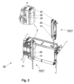
- figure 4 shows a perspective view of the continuous casting mold 30 of FIG 3 , now in a state when two strand guide devices 10 are attached or mounted to the adjusting devices 31 of the continuous casting mold 30.
- the bolts 28 are then engaged in the associated holding devices 29, resulting in a form-fitting attachment of the strand guide device 10 to the continuous casting mold 30.
- figure 5 shows another perspective view of the continuous casting mold 30, now in a state when both strand guide devices 10 are lifted up out of the continuous casting mold 30.
- a lifting of the strand guide devices 10 can be effected by attaching traction means to the ring eyes 30 and then pulling them upwards using a crane or the like.
- the 6 and 7 each show a perspective view of the continuous casting mold 30 of FIG 3 in a state when a front part 34 of the continuous casting mold 30 is mounted thereon.
- the strand guide devices 10 are shown in FIG 6 lifted out of the continuous casting mold 30 (in the same way as in figure 5 ), and in the representation of 7 used within the continuous casting mold.
- FIG 7 symbolized by the arrow "T".
- the strand guide devices 10 serve the strand guide devices 10, when they are mounted in the continuous casting mold 30, for the purpose of guiding a cast strand with a rectangular cross-section on its narrow side and supporting it appropriately.
- the guide rollers 14 of the strand guide devices 10 come into contact with the cast strand 12 immediately after the cast strand 12 has emerged from the continuous casting mold 30 .
- an edge region of the cast strand 12 with which the crowned-convex guide rollers 14 come into contact still has elastic properties.
- a strand guiding device 10 can also have a guide roller which is brought into contact with a longitudinal side of the cast strand 12 .
- a guide roller 15 also has a crowned, convex outer contour, as referred to above 1 explained, and serves to ensure that the introduction of a targeted concave embossing in the longitudinal side of the cast strand counteracts the tendency of the strand shell to bulge and thus compensates for such a bulging.
- the functioning of a guide roller 15, which is brought into contact with the longitudinal side of a cast strand corresponds, mutatis mutandis, to the functioning of a guide roller 14, which is set against the narrow side 12 of the cast strand 12.
- a strand guide device 10 for supporting a cast strand 12 with a rectangular cross section can have a plurality of guide rollers 14, 15 which are set against both the narrow side 22 of the cast strand 12 and the longitudinal side of the cast strand 12, namely at a point in time if the cast strand 12 still has elastic properties in areas close to the edge both on its narrow side and on its long side.
Landscapes
- Engineering & Computer Science (AREA)
- Mechanical Engineering (AREA)
- Continuous Casting (AREA)
- Guides For Winding Or Rewinding, Or Guides For Filamentary Materials (AREA)
Description
- Die Erfindung betrifft ein Verfahren zum Stützen eines Gießstrangs mit rechteckigen Querschnitt gemäß Anspruch 1.
- Nach dem Stand der Technik sind beim Stranggießen von Brammen mit einem rechteckigem Querschnitt Strangführungseinrichtungen bekannt, bei denen Führungsrollen, sog. Fußrollen, mit einer zylindrischen Außenkontur zur Strangstützung an der Schmalseite des Strangschalenkastens eingesetzt werden. In
Fig. 8 ist eine solche Führungsrolle, die eine zylindrische Außenkontur aufweist, im Querschnitt gezeigt. Mit solchen zylindrischen Fußrollen wird im Idealfall ein Führen bzw. Halten des Strangschalenkastens in Rechteckform erreicht. Jedoch hat der Gießstrang nach dem Kontakt mit solchen Fußrollen, d.h. in der Transportrichtung des Gießstrangs stromabwärts bzw. hinter diesen Fußrollen, das Bestreben wieder auszubauchen, bedingt durch den ferrostatischen Innendruck des Flüssigstahls und die innerhalb der Strangschale auftretenden Kriechvorgänge. In einem solchen Fall kommt es dann bei der erzeugten Bramme zu Abweichungen von dem gewünschten Querschnitt. - Ein weiterer Nachteil bei der Verwendung von Führungsrollen mit einer zylindrischen Außenkontur zum Stützen von Brammen besteht darin, dass an deren Kanten höhere Druckkräfte auftreten, weil die Strangschale durch den Innendruck des Flüssigstahls gegen die Rollenkante gepresst wird. Dies führt bei einer zu starken Anstellung der Führungsrolle gegen den Strangschalenkasten zu Druckstellen, die sich als sichtbare Laufbahnen auf der fertigen Bramme abbilden können.
- Aus
DE 101 19 550 A1 sind ein Verfahren und eine Vorrichtung zum Herstellen von Strangguss-Vormaterial bekannt. Hierbei wird ein Gießstrang einer - Vorprofilierung unterzogen, indem Rollen mit konvexen Außenkontur in die Oberfläche der Strangschale an deren Längsseite hineingedrückt werden. In Folge dessen wird an der Oberfläche des Gießstrangs an dessen Längsseite eine konkave Rille ausgebildet, wobei die konkave Rille durch den Einsatz von weiteren Rollen mit größerem Durchmesser vergrößert bzw. nachgeformt wird. Jedenfalls kommt es durch den Kontakt der Rollen mit konvexer Außenkontur zu einer dauerhaften Verformung des Gießstrangs, die nicht reversibel ist.
-
DE 195 20 939 C1 zeigt eine Strangführungseinrichtung mit den Merkmalen des Oberbegriffs von Anspruch 1 bzw. von Anspruch 3. Hierbei sind auslaufseitig an der Stranggieß-Kokille Träger vorgesehen, an denen Rollen zur Führung des Stranges angeordnet sind. Zur Anpassung an einen sich verändernden Schrumpf des Stranges ist vorgesehen, dass die Träger, und somit die daran angebrachten Rollen, quer zur Abzugsrichtung des Stranges verstellt werden können. Die einzelnen Rollen, die an den jeweiligen Trägern drehbar gelagert angebracht sind, haben jeweils einen zylindrischen Querschnitt, und unterliegen somit den vorstehend genannten Nachteilen. - Aus dem Artikel von Chang Ho Moon et.al. "Effect of the Roll Surface Profile on Centerline Segregation in Soft Reduction Process"; ISIJ International, Vol. 52 (2012), Nr. 7, 13. Juli 2012, Seiten 1266-1272 ist eine gattungsgemäße Strangführungseinrichtung mit den Merkmalen des Oberbegriffs von Anspruch 1 bzw. von Anspruch 3 bekannt.
- Entsprechend liegt der Erfindung die Aufgabe zugrunde, beim Stranggießen eines Gießstrangs dessen gewünschte Formgenauigkeit mit einfachen Mitteln zu optimieren.
- Diese Aufgabe wird durch ein Verfahren mit den in Anspruch 1 angegebenen Merkmalen gelöst. Eine vorteilhafte Weiterbildungen der Erfindung ist in dem abhängigen Anspruch definiert.
- Eine Strangführungseinrichtung dient zum Stützen eines Gießstrangs mit rechteckigem Querschnitt, nämlich wenn der Gießstrang in einer Transport- bzw. Abzugsrichtung aus der Stranggieß-Kokille austritt. Zu diesem Zweck umfasst die Strangführungseinrichtung zumindest eine Führungsrolle, die um eine Rotationsachse drehbar gelagert ist, wobei die Führungsrolle mit ihrer in Richtung der Rotationsachse verlaufenen Außenkontur mit dem Gießstrang in Kontakt gebracht werden kann, um den Gießstrang geeignet zu führen und zu stützen. Die Außenkontur der Führungsrolle ist konvex und derart ausgebildet, dass sie mit ihrer Längserstreckung entlang der Rotationsachse an eine Schmalseite des rechteckigen Gießstrangs angepasst ist. Dies bedeutet im Sinne der vorliegenden Erfindung, dass eine Gesamtlänge der Führungsrolle in Richtung ihrer Rotationsachse, und somit auch der Verlauf der ballig konvexen Außenkontur dieser Führungsrolle, maximal einer Länge des Strangschalenkastens an der Schmalseite des rechteckigen Gießstrangs entsprechen. Hierbei ist die konvexe Außenkontur der Führungsrolle ballig ausgebildet, wobei die konvex nach außen gewölbte Kurve der Führungsrolle unmittelbar an den Stirnseiten der Führungsrolle beginnt und in Richtung des mittigen Bereichs der Führungsrolle verläuft.
- Nach einer weiteren Ausgestaltung umfasst die Strangführungseinrichtung zumindest eine Führungsrolle, die um eine Rotationsachse drehbar gelagert ist, wobei die Führungsrolle mit ihrer in Richtung der Rotationsachse verlaufenen Außenkontur mit dem Gießstrang in Kontakt gebracht werden kann, um den Gießstrang geeignet zu führen und zu stützen. Die Außenkontur der Führungsrolle ist ballig konvex ausgebildet, wobei der größte Durchmesser der Außenkontur der Führungsrolle im Vergleich zu einem Durchmesser der Führungsrolle an den Rollenenden, d.h. an ihrer Stirnseite in dem Verhältnis maximal den Wert 1,5 und minimal den Wert 1,0 annimmt. Eine solche Führungsrolle kann dazu vorgesehen sein, entweder gegen die Schmalseite eines Gießstrangs oder gegen die Längsseite eines Gießstrangs angestellt zu werden.
- Bei der zuletzt genannten Ausführungsform ist die Außenkontur der Führungsrolle derart ausgebildet, dass sie mit ihrer Längserstreckung entlang der Rotationsachse an eine Schmalseite des rechteckigen Gießstrangs angepasst ist.
- In dem erfindungsgemäßen Verfahren zum Stützen eines Gießstrangs mit rechteckigem Querschnitt ist vorgesehen, dass zumindest eine drehbar gelagerte Führungsrolle eine ballig konvexe Außenkontur aufweist, wobei die Außenkontur der Führungsrolle durch eine durchgehende konvex nach außen gewölbte Kurve ohne Wendepunkt aus einem oder mehreren Radien ausgebildet ist, und die Führungsrolle mit dieser Außenkontur gegen eine Seite des Gießstrangs angestellt wird, während der Gießstrang in einem randnahen Bereich noch elastische Eigenschaften aufweist, wobei der größte Durchmesser (D_max) der Außenkontur der Führungsrolle im Vergleich zu einem Durchmesser (D_min) der Führungsrolle an ihrer Stirnseite in dem Verhältnis maximal den Wert 1,5 und minimal den Wert 1,0 annimmt, und dass in der Transportrichtung (T) des Gießstrangs mehrere Führungsrollen fluchtend hintereinander vorgesehen sind und gemeinsam gegen eine Seite des rechteckigen Gießstrangs angestellt werden, wobei für die einzelnen Führungsrollen - stromabwärts der Transportrichtung (T) des Gießstrangs - die Balligkeit der Außenkontur zunimmt, derart, dass der Quotient aus größtem Durchmesser (D_max) der Außenkontur einer Führungsrolle zum Durchmesser (D_min) der Führungsrolle an ihrer Stirnseite zunehmend ist.
- Der Erfindung liegt die wesentliche Erkenntnis zugrunde, dass der Strangschale des Gießstrangs, solange dieser unmittelbar nach dem Verlassen der Stranggieß-Kokille in einem randnahen Bereich noch elastische Eigenschaften aufweist, durch den Kontakt mit den Führungsrollen, die wie erläutert eine ballig konvexe Außenkontur aufweisen, eine gezielt konkave Formgebung aufgezwungen wird, die dem Bestreben der Strangschale zu einer Ausbauchung entgegenwirkt. Hierbei ist das Maß für die Balligkeit der Außenkontur einer Führungsrolle geeignet auf die jeweiligen Herstellungsparameter und die erzeugte Stahlsorte abgestimmt. Dies bedeutet, dass die Balligkeit der Außenkontur, die sich durch das Verhältnis des größten Durchmessers der Rollenoberfläche zu dem Durchmesser an den Rollenenden der Führungsrolle bestimmt, gerade nur so groß gewählt ist, wie es für eine Kompensation des Bestrebens der Strangschale zu einem Ausbauchen notwendig ist. Jedenfalls ist für die Erfindung von Bedeutung, dass durch den Kontakt der Strangschale des Gießstrangs mit einer Führungsrolle der Strangführungseinrichtung keine dauerhafte Umformung des Gießstrangs an der Stelle des Kontakts mit der Führungsrolle entstehen soll. Dies wird dadurch gewährleistet, dass die Führungsrolle der Strangführungseinrichtung mit dem Gießstrang zu einem Zeitpunkt in Kontakt gebracht wird, während der Gießstrang noch elastische Eigenschaften aufweist.
- Die ballig konvexe Außenkontur einer Führungsrolle ist auf die individuelle Problemstellung hin optimiert, die sich für eine bestimmte Stahlsorte und deren Herstellungsparameter darstellt. Entsprechend kann die ballig konvexe Außenkontur einer Führungsrolle in Anpassung an den Einzelfall verschieden ausgebildet sein, wobei sich das Verhältnis des größten Durchmessers der Rollenfläche zum Durchmesser der Rollenoberfläche an den Rollenenden, d.h. an einer Stirnseite der Führungsrolle in dem Bereich zwischen 1,5 und 1,0 bewegt. Innerhalb dieses Bereichs der beiden genannten Durchmesser relativ zu einander kann die Außenkontur der Führungsrolle auf den jeweiligen Einsatzfall geeignet angepasst sein.
- Dank der ballig konvexen Ausbildung der Außenkontur einer Führungsrolle, die gegen eine Seite des Gießstrangs unmittelbar nach dessen Verlassen der Stranggieß-Kokille angestellt wird, lässt sich die Ausbauchung des Gießstrangs bzw. einer Bramme ohne zu starke Kanteneffekte kompensieren.
- Idealerweise hebt sich das Maß, mit dem die Außenkontur einer Führungsrolle konvex ballig ausgebildet ist, mit dem Bestreben der Strangschale des Gießstrangs zu einem Ausbauchen zu Null auf. Im Ergebnis dieser Wechselwirkung, die aus dem Kontakt der ballig konvexen Außenkontur einer Führungsrolle mit der Strangschale des Gießstrangs resultiert, bildet sich für die Strangschale im Querschnitt eine gewünschte gleichmäßige Rechteckform.
- In vorteilhafter Weiterbildung der Erfindung ist die zumindest eine Führungsrolle der Strangführungseinrichtung in einer Käfighalterung drehbar gelagert aufgenommen. Eine solche Käfighalterung zeichnet sich durch einen robusten und preiswerten Aufbau aus, und gewährleistet eine sichere Drehhalterung für die Führungsrolle auch unter Berücksichtigung der beträchtlichen Kräfte, die beim Stranggießen auf die Führungsrolle einwirken.
- In vorteilhafter Weiterbildung der Erfindung kann vorgesehen sein, dass mehrere Führungsrollen mit jeweils einer ballig konvexen Außenkontur vorgesehen sind, wobei zumindest eine Führungsrolle gegen die Schmalseite eines Gießstrangs angestellt wird, und wobei zumindest eine weitere Führungsrolle gegen die Längsseite des Gießstrangs angestellt wird.
- Der Tendenz der Strangschale eines Gießstrangs zum Ausbauchen wird erfindungsgemäß dadurch entgegengewirkt, dass mehrere Führungsrollen vorgesehen sind, nämlich in der Transportrichtung des Gießstrangs fluchtend hintereinander. Zweckmäßigerweise sind alle diese Führungsrollen gemeinsam in einer Käfighalterung der Strangführungseinrichtung drehbar gelagert aufgenommen.
- Die Führungsrollen, die fluchtend hintereinander angeordnet sind, sind jeweils mit einer unterschiedlichen ballig konvexen Außenkontur versehen. Entsprechend bestehen für die fluchtend hintereinander angeordneten Führungsrollen unterschiedliche Konturausprägungen in Bezug auf deren ballig konvexe Außenkontur. Hierbei ist vorgesehen, dass bei einer Führungsrolle, die - in der Transportrichtung des Gießstrangs gesehen - weiter von der Stranggieß-Kokille beanstandet ist, der Quotient gebildet aus größtem Durchmesser der Außenkontur bzw. der Rollenoberfläche zum Durchmesser der Führungsrolle an ihrer Stirnseite größer ist als im Vergleich zu einer Führungsrolle, die - in der Transportrichtung des Gießstrangs gesehen - sich näher an der Stranggieß-Kokille befindet. In dieser Weise wird durch die Mehrzahl von Führungsrollen mit einer Balligkeit, die in der Transportrichtung des Gießstrangs zunimmt, ein schonendes Stützen für die Strangschale des Gießstrangs erreicht, um gleichzeitig dabei dem unerwünschten Ausbauchen der Strangschale entgegenzuwirken.
- In vorteilhafter Weiterbildung der Erfindung ist eine Verbindungseinrichtung vorgesehen, mit der die Strangführungseinrichtung an einer Stranggieß-Kokille oder angrenzend dazu formschlüssig angebracht werden kann. Die Führungsrollen werden beim Stranggie-ßen einem ausgeprägten Verschleiß unterworfen. Entsprechend ist es durch die Verbindungseinrichtung möglich, die Strangführungseinrichtung bei Bedarf von der Stranggieß-Kokille zu demontieren, und durch eine neue Strangführungseinrichtung auszutauschen. Zu diesem Zweck kann eine Hebeeinrichtung für die Strangführungseinrichtung vorgesehen sein, mittels der die Strangführungseinrichtung in vertikaler Richtung nach oben angehoben werden kann. Eine solche Hebeeinrichtung kann als Ringauge ausgebildet sein, das z.B. an einer Oberseite der Käfighalterung befestigbar ist, z.B. durch eine Schraubverbindung.
- Durch eine Ausstattung der Strangführungseinrichtung mit der genannten Verbindungseinrichtung ist es somit möglich, eine austauschbare Rolleneinheit für das Stranggießen bereitzustellen, die bei Bedarf - entweder im Falle eines Verschleißes oder zur Anpassung an spezielle Stahlsorten - in kurzer Zeit ausgetauscht werden kann. Zu diesem Zweck kann die Strangführungseinrichtung mittels der Hebeeinrichtung von einem Kran oder dergleichen vertikal nach oben aus der Stranggieß-Kokille herausgehoben werden.
- In vorteilhafter Weiterbildung umfasst die Strangführungseinrichtung auch eine längliche Kupferplatte, die - in der Transportrichtung des Gießstrangs gesehen - stromaufwärts der Führungsrolle(n) vorgesehen ist. Zweckmäßigerweise kann hierbei die Kupferplatte an der genannten Käfighalterung angebracht sein. In dieser Weise bilden die Käfighalterung, in der zumindest eine Führungsrolle drehbar gelagert aufgenommen ist, und die daran angebrachte Kupferplatte ein vorteilhaftes Austauschmodul, dass bei Bedarf schnell von der Stranggieß-Kokille demontiert werden kann und sich somit austauschen lässt.
- Nachstehend sind Ausführungsbeispiele der Erfindung anhand einer schematisch vereinfachten Zeichnung im Detail beschrieben.
- Es zeigen:
-
Fig. 1a-c
jeweils Seitenansichten von Führungsrollen nach verschiedenen Ausführungsformen, -
Fig. 2
eine Perspektivansicht und eine Seitenansicht einer Strangführungseinrichtung, -
Fig. 3-5
jeweils Perspektivansichten einer, zu Zwecken der Veranschaulichung, teilweise demontierten Stranggieß-Kokille (Ausschnitt der Gießform), in Verbindung mit Strangführungseinrichtungen, -
Fig. 6
eine Perspektivansicht einer Stranggießkokille (Ausschnitt der Gießform), aus der Strangführungseinrichtungen herausgehoben sind, -
Fig. 7
eine Perspektivansicht einer Stranggießkokille (Ausschnitt der Gießform), in der die Strangführungseinrichtungen bestimmungsgemäß eingebaut sind, und -
Fig. 8
eine Seitenansicht einer herkömmlichen Führungsrolle. - Beschrieben wird eine Strangführungseinrichtung 10 zum Führen und Stützen eines Gießstrangs 12, wobei die Strangführungseinrichtung 10 zu diesem Zweck zumindest eine drehbar gelagerte Führungsrolle 14 aufweist.
- In den
Fig. 1a, 1b und 1c sind jeweils verschiedene Ausführungsformen für eine Führungsrolle 14 im Querschnitt dargestellt. Die Führungsrollen 14 sind jeweils um eine Rotationsachse 16 drehbar gelagert, und haben eine in der Längserstreckung entlang der Rotationsachse 16 verlaufende Außenkontur 18, die ballig konvex ausgebildet ist. Hierbei ist ein maximaler Durchmesser D_max einer Führungsrolle 14, der in etwa in einem mittigen Bereich 20 hiervon vorliegt, größer als ein minimaler Durchmesser D_min der Führungsrolle, der an einem Rollenende bzw. an einer Stirnseite 19 der Führungsrolle 14 vorliegt. Die Ausbildung der ballig konvexen Außenkontur 18 einer Führungsrolle 14 ist derart gewählt, dass das Verhältnis von maximalem Durchmesser D_max der Rollenoberfläche zum minimalen Durchmesser an einem Rollenende bzw. an einer Stirnseite der Führungsrolle 14 die Bedingung erfüllt:
- Ein Vergleich der verschiedenen Ausführungsformen für eine Führungsrolle 14 nach den
Figuren 1a, 1b bzw. 1c verdeutlicht, dass die Radien für die konvexe Außenkontur 18, mit denen jeweils die Balligkeit für die einzelnen Führungsrollen 14 definiert wird, unterschiedlich sind. - Bei den Ausführungsformen gemäß
Fig. 1a und Fig. 1b weist die Außenkontur 18 der Führungsrolle 14 ausgehend von ihren Stirnseiten 19 zunächst einen gleichbleibenden Durchmesser auf. Dieser Bereich, in dem die Außenkontur 18 zunächst zylindrisch ist, kann eine Längserstreckung zwischen 5-50 mm aufweisen. Erst im Anschluss an diesen zylindrischen Bereich nimmt die Außenkontur 18 einen kurvenförmigen Verlauf an, wie erläutert in ballig konvexer Form. - Bei der Ausführungsform gemäß
Fig. 1b nimmt der Durchmesser der Außenkontur 18 der Führungsrolle 14 ausgehend von der Stirnseite 19 in Richtung des mittigen Bereichs 20 bis zu einem Wendepunkt W zu, wobei ab diesem Wendepunkt die Zunahme bzw. das Anwachsen des Durchmessers bis zum Erreichen des mittigen Bereichs 20 wieder abnimmt. Der kurvenförmige Verlauf der Außenkontur 18 bis zu dem Wendepunkt W, ausgehend von der Stirnseite 19, ist durch einen ersten Radius R1 definiert, wobei der kurvenförmige Verlauf der Außenkontur 18 zwischen dem Wendepunkt W und dem mittigen Bereich 20 durch einen zweiten Radius R2 definiert ist. Hierbei können der erste und zweite Radius R1, R2 jeweils einen Wert von 1mm oder mehr annehmen, wodurch für die Außenkontur 18 "weiche" Rundungen gewährleistet sind. - Für eine vereinfachte Darstellung sind bei der Ausführungsform von
Fig. 1b die Radien R1, R2 und der Wendepunkt W nur für den Bereich der Führungswalze 14 links der Mitte gezeigt. Es versteht sich, dass die Führungswalze 14 vorzugsweise symmetrisch bezüglich ihrer Mitte ausgebildet ist, so dass die Radien R1, R2 und der Wendepunkt W für die Außenkontur 18 auch in dem Bereich rechts von der Mitte vorgesehen sind. - Ein weiteres Merkmal der Ausführungsform gemäß
Fig. 1b besteht darin, dass der mittigen Bereich 20 der Außenkontur 18 der Führungsrolle 14 einen unveränderlichen Durchmesser aufweist, und somit zylindrisch ausgebildet ist. - Die Ausführungsformgemäß
Fig. 1c ist dadurch charakterisiert, dass deren Außenkontur 18 durch eine durchgehende konvex nach außen gewölbte Kurve ohne Wendepunkt ausgebildet ist, wobei diese Kurve einen oder mehrere Radien aufweisen kann. Diese nach außen gewölbte Kurve kann einen vorbestimmten Abstand zur Stirnseite 19 der Führungsrolle 14 aufweisen, wobei bei der Darstellung gemäßFig. 1c dieser vorbestimmte Abstand den Wert null hat. Anders ausgedrückt, beginnt bei der Ausführungsform gemäßFig. 1c die konvex nach außen gewölbte Kurve unmittelbar an den Stirnseiten 19 der Führungsrolle 14, und verläuft dann in Richtung des mittigen Bereichs 20. Alternativ hierzu ist es möglich, dass bei dieser Ausführungsform der vorbestimmte Abstand zur Stirnseite 19, an dem die nach außen gewölbte Kurve für die Außenkontur 18 einsetzt, einen Wert von bis zu 50 mm aufweist. - Nach einer weiteren (nicht dargestellten) Ausführungsform ist z.B. eine Kombination der
Fig. 1b und Fig. 1c möglich. Dies bedeutet, dassdie nach außen gewölbte Kurve der Außenkontur 18, so wie inFig. 1c veranschaulicht, in ihrem mittigen Bereich 20 einen zylindrischen Bereich mit unveränderlichem Durchmesser aufweisen kann, so wie bei derFig. 1b veranschaulicht. - Eine Führungsrolle 14 der Strangführungseinrichtung 10 dient zu dem Zweck, gegen einen Strangschalenkasten 21 des Gießstrangs 12 angestellt zu werden. In den
Fig. 1a, 1b und 1c ist jeweils verdeutlicht, dass eine Führungsrolle 14 gegen eine Schmalseite 22 des Gießstrangs 12, der einen rechteckigen Querschnitt aufweist, gedrückt bzw. angestellt wird. Es ist zu erkennen, dass hierbei eine Länge der Führungsrolle 14 entlang ihrer Rotationsachse 16 kürzer ist als eine Länge der Schmalseite 22 des Gießstrangs 12. In dieser Weise ist die Außenkontur 18 einer Führungsrolle 14 mit ihrer Längserstreckung entlang der Rotationsachse 16 an die Schmalseite 22 des Gießstrangs 12 mit rechteckigem Querschnitt angepasst. - In den
Fig. 1a-1c ist mit dem Bezugszeichen "23" jeweils ein noch flüssiger Sumpf des Gießstrangs 12 symbolisiert. Demgegenüber ist ein Randbereich des Gießstrangs 12 insbesondere an einer Schmalseite 22 davon, mit dem die Führungsrolle 14 in Kontakt gebracht wird, bereits verfestigt, jedoch nur in dem Maße, dass ein solch verfestigter Bereich des Gießstrangs 12 noch elastische Eigenschaften aufweist. - Bei einem Kontakt mit der ballig konvexen Außenkontur 18 einer Führungsrolle 14 wird der Schmalseite 22 des Gießstrangs 12 eine entsprechend konkave Prägung aufgezwungen, wie dies in den jeweiligen Querschnittsansichten der
Fig. 1a - 1c veranschaulicht ist. Wie bereits erläutert, ist in diesem Zusammenhang von Bedeutung, dass diese konkave Prägung, für die Beispiele gemäß derFig. 1a-1c an der Schmalseite 22 des Gießstrangs 12, in den Randbereich des Gießstrangs 12 eingebracht wird, solange dieser noch elastische Eigenschaften aufweist. Somit wird durch das Einbringen einer solch konkaven Prägung erreicht, dass das Bestreben des Gießstrangs 12 zu einem Ausbauchen, wenn in Folge einer Bewegung des Gießstrangs in seiner Transportrichtung T kein weiterer Kontakt zu einer Führungsrolle 14 besteht, kompensiert wird und sich im Idealfall zu Null aufhebt. Hieraus resultiert dann eine ideale Rechteckform für den Strangschalenkasten 21 des Gießstrangs 12. -
Fig. 2 zeigt eine weitere Ausführungsform für eine Strangführungseinrichtung 10, hier sowohl in einer Perspektivansicht (oberer Bereich vonFig. 2 ) als auch in einer Seitenansicht (unterer Bereich vonFig. 2 ). Bei dieser Ausführungsform umfasst die Strangführungseinrichtung 10 eine Käfighalterung 24, an bzw. in der eine Mehrzahl von Führungsrollen 14 drehbar gelagert angebracht sind. Des Weiteren ist eine Kupferplatte 26 vorgesehen, die an der Käfighalterung 24 angebracht ist. In Bezug auf eine Transportrichtung bzw. Abzugsrichtung des Gießstrangs 12, in derFig. 2 symbolisch mit dem Pfeil "T" bezeichnet, ist die Kupferplatte 26 stromaufwärts von der Käfighalterung 24 vorgesehen. - Für die Ausführungsform einer Strangführungseinrichtung 10 gemäß
Fig. 2 wird gesondert darauf hingewiesen, dass die Kombination einer Käfighalterung 24 mit einer daran angebrachten Kupferplatte 26 ein Austauschmodul 27 bildet, das sich bei Bedarf in kurzer Zeit austauschen bzw. ersetzen lässt. Für dieses Austauschmodul 27 kann - gemäß der Darstellung vonFig. 2 - vorgesehen sein, dass an der Käfighalterung 24 eine Mehrzahl von Führungsrollen 14 angebracht ist. Abweichend von der Darstellung inFig. 2 kann auch vorgesehen sein, dass an der Käfighalterung 24 lediglich eine einzige Führungsrolle 14 drehbar gelagert angebracht ist. - Falls an der Käfighalterung 24 mehrere Führungsrollen 14 angebracht sind, so wird diesbezüglich darauf hingewiesen, dass deren Außenkontur 18 jeweils eine unterschiedlich große Balligkeit aufweist, mit der Maßgabe, dass die Balligkeit, d.h. der vorstehend genannte Quotient D_max/D_min, in Richtung der Transportbewegung T des Gießstrangs 12 zunimmt. Anders ausgedrückt, wird die Balligkeit einer entsprechenden Führungsrolle 14 umso größer, je weiter sie von einer (in
Fig. 2 nicht gezeigten) Stranggieß-Kokille beanstandet ist. - Der Einsatz der Strangführungseinrichtung 10 als Austauschmodul 27 wird dadurch ermöglicht, dass sie eine Verbindungseinrichtung 28 aufweist, mittels der die Strangführungseinrichtung 10 an einer Stranggieß-Kokille 30 (
Fig. 3 ) oder angrenzend dazu formschlüssig angebracht werden kann. Beispielsweise ist diese Verbindungseinrichtung in Form eines seitlichen Bolzens 28 ausgebildet, der in eine komplementär hierzu ausgebildete Halteeinrichtung 29 der Stranggieß-Kokille 30 oder eines zugehörigen Verstellelements 31 einrasten kann. An einer Oberseite der Kupferplatte 26 ist eine Hebeeinrichtung 32, z.B. in Form eines Ringauges, eingeschraubt. Somit kann die Strangführungseinrichtung 10 durch einen Kran oder dergleichen in vertikaler Richtung angehoben werden, um entweder in die Stranggieß-Kokille 30 eingesetzt oder daraus herausgehoben zu werden. - In der Perspektivansicht gemäß
Fig. 3 ist die Stranggieß-Kokille 30, zu Zwecken einer vereinfachten Darstellung, teilweise demontiert gezeigt. Somit ist zu erkennen, in welcher Weise eine Strangführungseinrichtung 10 an der Stranggieß-Kokille 30 anbringbar ist. Im Bildbereich links ist eine Strangführungseinrichtung 10 derart gezeigt, dass deren Bolzen 28 sich knapp oberhalb der Halteeinrichtungen 29, die an den freien Enden der jeweiligen Verstellelemente 31 vorgesehen sind, befinden. Im Bildbereich rechts ist eine Strangführungseinrichtung 10 in einem Zustand gezeigt, wenn sie aus der Stranggieß-Kokille 30 herausgehoben ist. -
Figur 4 zeigt eine Perspektivansicht der Stranggieß-Kokille 30 vonFig. 3 , nunmehr in einem Zustand, wenn zwei Strangführungseinrichtungen 10 an den Verstelleinrichtungen 31 der Stranggieß-Kokille 30 angebracht bzw. montiert sind. Hierbei sind dann die Bolzen 28 in den zugeordneten Halteeinrichtungen 29 jeweils eingerastet, wodurch sich eine formschlüssige Anbringung der Strangführungseinrichtung 10 an der Stranggieß-Kokille 30 ergibt. -
Fig. 5 zeigt eine weitere Perspektivansicht der Stranggieß-Kokille 30, nunmehr in einem Zustand, wenn beide Strangführungseinrichtungen 10 nach oben aus der Stranggieß-Kokille 30 herausgehoben sind. Wie bereits erwähnt, kann ein solches Herausheben der Strangführungseinrichtungen 10 dadurch erfolgen, dass Zugmittel an den Ringaugen 30 angebracht werden und anschließend durch einen Kran oderdergleichen nach oben gezogen werden. - Die
Fig. 6 undFig. 7 zeigen jeweils eine Perspektivansicht der Stranggieß-Kokille 30 vonFig. 3 in einem Zustand, wenn ein vorderer Teil 34 der Stranggieß-Kokille 30 daran montiert ist. Im Einzelnen sind die Strangführungseinrichtungen 10 in der Darstellung vonFig. 6 aus der Stranggieß-Kokille 30 herausgehoben (in gleicher Weise wie beiFig. 5 ), und in der Darstellung vonFig. 7 innerhalb der Stranggieß-Kokille eingesetzt. Zur Verdeutlichung einer Transport- bzw. Abzugsrichtung des Gießstrangs 12 in Bezug zur Stranggieß-Kokille 30 ist diese Richtung in der Darstellung vonFig. 7 durch den Pfeil "T" symbolisiert. - Für das Ausführungsbeispiel nach den
Fig. 3-7 dienen die Strangführungseinrichtungen 10, wenn sie in der Stranggieß-Kokille 30 montiert sind, zu dem Zweck, einen Gießstrang mit rechteckigem Querschnitt an dessen Schmalseite zu führen und dabei geeignet zu stützen. Wie ersichtlich, kommen dabei die Führungsrollen 14 der Strangführungseinrichtungen 10 mit dem Gießstrang 12 in Kontakt, unmittelbar nachdem der Gießstrang 12 aus der Stranggieß-Kokille 30 ausgetreten ist. Entsprechend weist ein Randbereich des Gießstrangs 12, mit dem die ballig-konvexen Führungsrollen 14 in Kontakt gelangen, noch elastische Eigenschaften auf. Dies führt dann dazu, dass diesem Randbereich des Gießstrangs 12, durch den Kontakt mit den ballig-konvexen Führungsrollen 14, eine konkave Prägung aufgezwungen wird, wobei sich das Bestreben der Strangschale des Gießstrangs 12 zu einem Ausbauchen, nämlich nachdem der Gießstrang 12 an den Führungsrollen 14 vorbeigetreten ist und dann keinen Kontakt mehr zu den Führungsrollen 14 hat, mit der konkaven Prägung zu Null aufhebt. - Gemäß einer weiteren vorteilhaften Ausführungsform kann eine Strangführungseinrichtung 10 auch eine Führungsrolle aufweisen, die in Kontakt mit einer Längsseite des Gießstrangs 12 gebracht wird. Beispielsweise ist eine solche Führungsrolle in der Darstellung von
Fig. 5 gezeigt, und dort mit dem Bezugszeichen "15" versehen. Eine solche Führungsrolle 15 weist ebenfalls eine ballig konvexe Außenkontur auf, wie vorstehend unter Bezugnahme aufFig. 1 erläutert, und dient dazu, dass das Einbringen einer gezielten konkaven Prägung in die Längsseite des Gießstrangs dem Bestreben eines Ausbauchens der Strangschale entgegenwirkt und somit ein solches Ausbauchen kompensiert. Insoweit entspricht die Funktionsweise einer Führungsrolle 15, die in Kontakt mit der Längsseite eines Gießstrangs gebracht wird, mutatis mutandis der Funktionsweise einer Führungsrolle 14, die gegen die Schmalseite 12 des Gießstrangs 12 angestellt wird. - Schließlich sei darauf hingewiesen, dass eine Strangführungseinrichtung 10 zum Stützen eines Gießstrangs 12 mit rechteckigem Querschnitt mehrere Führungsrollen 14, 15 aufweisen kann, die sowohl gegen die Schmalseite 22 des Gießstrangs 12 als auch gegen die Längsseite des Gießstrangs 12 angestellt werden, nämlich zu einem Zeitpunkt, wenn der Gießstrang 12 in randnahen Bereichen sowohl an seiner Schmal - und Längsseite noch elastische Eigenschaften aufweist.
-
- 10
- Strangführungseinrichtung
- 12
- Gießstrang
- 14
- Führungsrolle (an der Schmalseite des Gießstrangs 12)
- 15
- Führungsrolle (an der Längsseite des Gießstrangs 12)
- 16
- Rotationsachse (der Führungsrolle 14)
- 18
- Außenkontur (der Führungsrolle 14)
- 19
- Stirnseite (der Führungsrolle 14)
- 20
- Mittiger Bereich (der Führungsrolle 14)
- 21
- Strangschalenkasten (des Gießstrangs 12)
- 22
- Schmalseite (des Gießstrangs 12)
- 23
- Flüssiger Sumpf (innerhalb des Gießstrangs 12)
- 24
- Käfighalterung
- 26
- Kupferplatte
- 27
- Austauschmodul
- 28
- Verbindungseinrichtung
- 29
- Halteeinrichtung
- 30
- Stranggieß-Kokille
- 31
- Verstelleinrichtung (der Stranggieß-Kokille 30)
- 32
- Hebeeinrichtung
- 34
- Vorderer Teil (der Stranggieß-Kokille 30)
- 36
- Herkömmliche zylindrische Rolle
- T
- Transportrichtung (des Gießstrangs 12)
Claims (2)
- Verfahren zum Stützen eines Gießstrangs (12) mit rechteckigem Querschnitt, bei dem zumindest eine drehbar gelagerte Führungsrolle (14) eine ballig konvexe Außenkontur (18) aufweist, wobei die Außenkontur (18) der Führungsrolle (14; 15) durch eine durchgehende konvex nach außen gewölbte Kurve ohne Wendepunkt aus einem oder mehreren Radien ausgebildet ist, und die Führungsrolle (14) mit dieser Außenkontur (18) gegen eine Seite des Gießstrangs (12) angestellt wird, während der Gießstrang (12) in einem randnahen Bereich noch elastische Eigenschaften aufweist, wobei der größte Durchmesser (D_max) der Außenkontur (18) der Führungsrolle (14; 15) im Vergleich zu einem Durchmesser (D_min) der Führungsrolle (14; 15) an ihrer Stirnseite (19) in dem Verhältnis maximal den Wert 1,5 und minimal den Wert 1,0 annimmt, und dass in der Transportrichtung (T) des Gießstrangs (12) mehrere Führungsrollen (14) fluchtend hintereinander vorgesehen sind und gemeinsam gegen eine Seite des rechteckigen Gießstrangs (12) angestellt werden, wobei für die einzelnen Führungsrollen (14) - stromabwärts der Transportrichtung (T) des Gießstrangs (12) - die Balligkeit der Außenkontur (18) zunimmt, derart, dass der Quotient aus größtem Durchmesser (D_max) der Außenkontur (18) einer Führungsrolle (14) zum Durchmesser (D_min) der Führungsrolle (14) an ihrer Stirnseite zunehmend ist.
- Verfahren nach Anspruch 1, dadurch gekennzeichnet, dass mehrere drehbar gelagerte Führungsrollen (14; 15) mit jeweils einer ballig konvexen Außenkontur (18) vorgesehen sind, wobei zumindest eine Führungsrolle (14) gegen eine Schmalseite (22) des Gießstrangs (12) angestellt wird, und wobei zumindest eine weitere Führungsrolle (15) gegen eine Längsseite (22) des Gießstrangs (12) angestellt wird.
Applications Claiming Priority (2)
| Application Number | Priority Date | Filing Date | Title |
|---|---|---|---|
| DE102016206454 | 2016-04-18 | ||
| DE102017200983.7A DE102017200983A1 (de) | 2016-04-18 | 2017-01-23 | Strangführungseinrichtung und Verfahren zum Stützen eines Gießstrangs |
Publications (3)
| Publication Number | Publication Date |
|---|---|
| EP3235579A1 EP3235579A1 (de) | 2017-10-25 |
| EP3235579B1 EP3235579B1 (de) | 2020-05-13 |
| EP3235579B2 true EP3235579B2 (de) | 2023-08-30 |
Family
ID=58672280
Family Applications (1)
| Application Number | Title | Priority Date | Filing Date |
|---|---|---|---|
| EP17163459.5A Active EP3235579B2 (de) | 2016-04-18 | 2017-03-29 | Strangführungseinrichtung und verfahren zum stützen eines giessstrangs |
Country Status (1)
| Country | Link |
|---|---|
| EP (1) | EP3235579B2 (de) |
Family Cites Families (11)
| Publication number | Priority date | Publication date | Assignee | Title |
|---|---|---|---|---|
| US3837392A (en) * | 1971-11-18 | 1974-09-24 | I Rossi | Apparatus for continuously casting steel slabs |
| US3900066A (en) | 1974-01-02 | 1975-08-19 | Allis Chalmers | Apparatus for continuous casting a metal strand shaped to provide concave surfaces |
| GB1596395A (en) | 1977-12-14 | 1981-08-26 | Jernkontoret Forskningsavdelni | Method of continuous casting of steels or metal alloys with segregation tendancy and apparatus for carrying out the method |
| DE3427708C2 (de) | 1984-07-27 | 1986-09-04 | Krupp Stahl Ag, 4630 Bochum | Vorrichtung zum seitlichen Führen eines Stranges einer Knüppel-Stranggießanlage |
| DE4403047C1 (de) * | 1994-01-28 | 1995-08-10 | Mannesmann Ag | Strangführungsgerüst |
| DE4403046C1 (de) | 1994-01-28 | 1995-08-17 | Mannesmann Ag | Rolle für ein Strangführungsgerüst |
| DE4403045C1 (de) * | 1994-01-28 | 1995-09-07 | Mannesmann Ag | Stranggießanlage zum Führen von Strängen |
| DE19520939C1 (de) | 1995-06-02 | 1996-07-25 | Mannesmann Ag | Verstelleinrichtung für Führungsrollen in Stranggießanlagen |
| DE10119550A1 (de) | 2001-04-21 | 2002-10-24 | Sms Demag Ag | Verfahren und Vorrichtung zum Herstellen von Stranggu-Vormaterial |
| JP2003094154A (ja) | 2001-09-21 | 2003-04-02 | Sanyo Special Steel Co Ltd | 鋼の連続鋳造方法 |
| KR101264635B1 (ko) | 2010-11-19 | 2013-05-24 | 주식회사 포스코 | 주편 압하 장치 및 이를 이용한 연속주조 방법 |
-
2017
- 2017-03-29 EP EP17163459.5A patent/EP3235579B2/de active Active
Also Published As
| Publication number | Publication date |
|---|---|
| EP3235579A1 (de) | 2017-10-25 |
| EP3235579B1 (de) | 2020-05-13 |
Similar Documents
| Publication | Publication Date | Title |
|---|---|---|
| AT506549B1 (de) | Strangführungssegment | |
| DE2501956C2 (de) | Vorrichtung zum Stützen, Führen, Biegen bzw. Richten und Verformen eines breiten Gußstranges | |
| EP2056981A1 (de) | Strangführungseinrichtung und verfahren zum führen eines noch nicht durcherstarrten metallbandes | |
| DE3132815A1 (de) | Verfahren und einrichtung zum geraderichten von stahlrohren und dergleichen | |
| DE4306853C2 (de) | Strangführungsgerüst | |
| DE102008009136A1 (de) | Strangführung, insbesondere für eine Stahlbrammen-Stranggießanlage | |
| DE2416625A1 (de) | Fuehrungswalzensegment fuer gusstuecke in einer stranggiesseinrichtung | |
| DE10218779B4 (de) | Lagerung der beiden Walzen einer Walzenmühle | |
| EP3235579B1 (de) | Strangführungseinrichtung und verfahren zum stützen eines giessstrangs | |
| DE102021207301A1 (de) | Strangführungseinrichtung und Verfahren zum Stranggießen eines metallischen Produkts in einer Stranggießanlage mit einer solchen Strangführungseinrichtung | |
| DE69924466T2 (de) | Abstreifvorrichtung für flüssigkeiten | |
| EP1313580B1 (de) | Vorrichtung zum stranggiessen von metallen, insbesondere von stahl | |
| WO2006056423A1 (de) | Vorrichtung und verfahren zum stranggiessen | |
| DE2731748B2 (de) | Rollenführungsgerüst für eine Stahlstranggießanlage | |
| DE102015202608A1 (de) | Gießanlage | |
| DE69005049T2 (de) | Verfahren und Vorrichtung zum Stranggiessen mit Doppelrollen von dünnen metallischen Produkten, geeignet zum Kaltwalzen. | |
| WO2002090019A1 (de) | VERFAHREN UND VORRICHTUNG ZUM STRANGGIEssEN VON BLÖCKEN, BRAMMEN ODER DÜNNBRAMMEN | |
| DE102017200983A1 (de) | Strangführungseinrichtung und Verfahren zum Stützen eines Gießstrangs | |
| EP3097995B1 (de) | Segment einer strangführung einer stranggiessanlage und stranggiessanlage | |
| EP2648865B1 (de) | Stranggiessanlage zum giessen eines metallstranges | |
| EP4489928B1 (de) | Bogensegment einer strangführungseinrichtung | |
| DE102022212862A1 (de) | Strangführungseinrichtung zum Stützen eines Gießstrangs | |
| DE102005038574A1 (de) | Walzgerüst und Walzvorrichtung zum Walzen eines Walzprodukts | |
| DE202012012284U1 (de) | Strangführung für eine Stranggießanlage | |
| DE2754405A1 (de) | Strangfuehrung fuer eine stahlstranggiessanlage |
Legal Events
| Date | Code | Title | Description |
|---|---|---|---|
| PUAI | Public reference made under article 153(3) epc to a published international application that has entered the european phase |
Free format text: ORIGINAL CODE: 0009012 |
|
| STAA | Information on the status of an ep patent application or granted ep patent |
Free format text: STATUS: EXAMINATION IS IN PROGRESS |
|
| 17P | Request for examination filed |
Effective date: 20170329 |
|
| AK | Designated contracting states |
Kind code of ref document: A1 Designated state(s): AL AT BE BG CH CY CZ DE DK EE ES FI FR GB GR HR HU IE IS IT LI LT LU LV MC MK MT NL NO PL PT RO RS SE SI SK SM TR |
|
| AX | Request for extension of the european patent |
Extension state: BA ME |
|
| RBV | Designated contracting states (corrected) |
Designated state(s): AL AT BE BG CH CY CZ DE DK EE ES FI FR GB GR HR HU IE IS IT LI LT LU LV MC MK MT NL NO PL PT RO RS SE SI SK SM TR |
|
| GRAP | Despatch of communication of intention to grant a patent |
Free format text: ORIGINAL CODE: EPIDOSNIGR1 |
|
| STAA | Information on the status of an ep patent application or granted ep patent |
Free format text: STATUS: GRANT OF PATENT IS INTENDED |
|
| INTG | Intention to grant announced |
Effective date: 20191122 |
|
| GRAS | Grant fee paid |
Free format text: ORIGINAL CODE: EPIDOSNIGR3 |
|
| TPAC | Observations filed by third parties |
Free format text: ORIGINAL CODE: EPIDOSNTIPA |
|
| GRAA | (expected) grant |
Free format text: ORIGINAL CODE: 0009210 |
|
| STAA | Information on the status of an ep patent application or granted ep patent |
Free format text: STATUS: THE PATENT HAS BEEN GRANTED |
|
| AK | Designated contracting states |
Kind code of ref document: B1 Designated state(s): AL AT BE BG CH CY CZ DE DK EE ES FI FR GB GR HR HU IE IS IT LI LT LU LV MC MK MT NL NO PL PT RO RS SE SI SK SM TR |
|
| REG | Reference to a national code |
Ref country code: GB Ref legal event code: FG4D Free format text: NOT ENGLISH |
|
| REG | Reference to a national code |
Ref country code: CH Ref legal event code: EP |
|
| REG | Reference to a national code |
Ref country code: DE Ref legal event code: R096 Ref document number: 502017005203 Country of ref document: DE |
|
| REG | Reference to a national code |
Ref country code: AT Ref legal event code: REF Ref document number: 1269595 Country of ref document: AT Kind code of ref document: T Effective date: 20200615 |
|
| REG | Reference to a national code |
Ref country code: LT Ref legal event code: MG4D |
|
| REG | Reference to a national code |
Ref country code: NL Ref legal event code: MP Effective date: 20200513 |
|
| PG25 | Lapsed in a contracting state [announced via postgrant information from national office to epo] |
Ref country code: IS Free format text: LAPSE BECAUSE OF FAILURE TO SUBMIT A TRANSLATION OF THE DESCRIPTION OR TO PAY THE FEE WITHIN THE PRESCRIBED TIME-LIMIT Effective date: 20200913 Ref country code: PT Free format text: LAPSE BECAUSE OF FAILURE TO SUBMIT A TRANSLATION OF THE DESCRIPTION OR TO PAY THE FEE WITHIN THE PRESCRIBED TIME-LIMIT Effective date: 20200914 Ref country code: FI Free format text: LAPSE BECAUSE OF FAILURE TO SUBMIT A TRANSLATION OF THE DESCRIPTION OR TO PAY THE FEE WITHIN THE PRESCRIBED TIME-LIMIT Effective date: 20200513 Ref country code: SE Free format text: LAPSE BECAUSE OF FAILURE TO SUBMIT A TRANSLATION OF THE DESCRIPTION OR TO PAY THE FEE WITHIN THE PRESCRIBED TIME-LIMIT Effective date: 20200513 Ref country code: LT Free format text: LAPSE BECAUSE OF FAILURE TO SUBMIT A TRANSLATION OF THE DESCRIPTION OR TO PAY THE FEE WITHIN THE PRESCRIBED TIME-LIMIT Effective date: 20200513 Ref country code: GR Free format text: LAPSE BECAUSE OF FAILURE TO SUBMIT A TRANSLATION OF THE DESCRIPTION OR TO PAY THE FEE WITHIN THE PRESCRIBED TIME-LIMIT Effective date: 20200814 Ref country code: NO Free format text: LAPSE BECAUSE OF FAILURE TO SUBMIT A TRANSLATION OF THE DESCRIPTION OR TO PAY THE FEE WITHIN THE PRESCRIBED TIME-LIMIT Effective date: 20200813 |
|
| PG25 | Lapsed in a contracting state [announced via postgrant information from national office to epo] |
Ref country code: BG Free format text: LAPSE BECAUSE OF FAILURE TO SUBMIT A TRANSLATION OF THE DESCRIPTION OR TO PAY THE FEE WITHIN THE PRESCRIBED TIME-LIMIT Effective date: 20200813 Ref country code: LV Free format text: LAPSE BECAUSE OF FAILURE TO SUBMIT A TRANSLATION OF THE DESCRIPTION OR TO PAY THE FEE WITHIN THE PRESCRIBED TIME-LIMIT Effective date: 20200513 Ref country code: RS Free format text: LAPSE BECAUSE OF FAILURE TO SUBMIT A TRANSLATION OF THE DESCRIPTION OR TO PAY THE FEE WITHIN THE PRESCRIBED TIME-LIMIT Effective date: 20200513 Ref country code: HR Free format text: LAPSE BECAUSE OF FAILURE TO SUBMIT A TRANSLATION OF THE DESCRIPTION OR TO PAY THE FEE WITHIN THE PRESCRIBED TIME-LIMIT Effective date: 20200513 |
|
| PG25 | Lapsed in a contracting state [announced via postgrant information from national office to epo] |
Ref country code: AL Free format text: LAPSE BECAUSE OF FAILURE TO SUBMIT A TRANSLATION OF THE DESCRIPTION OR TO PAY THE FEE WITHIN THE PRESCRIBED TIME-LIMIT Effective date: 20200513 Ref country code: NL Free format text: LAPSE BECAUSE OF FAILURE TO SUBMIT A TRANSLATION OF THE DESCRIPTION OR TO PAY THE FEE WITHIN THE PRESCRIBED TIME-LIMIT Effective date: 20200513 |
|
| PG25 | Lapsed in a contracting state [announced via postgrant information from national office to epo] |
Ref country code: EE Free format text: LAPSE BECAUSE OF FAILURE TO SUBMIT A TRANSLATION OF THE DESCRIPTION OR TO PAY THE FEE WITHIN THE PRESCRIBED TIME-LIMIT Effective date: 20200513 Ref country code: DK Free format text: LAPSE BECAUSE OF FAILURE TO SUBMIT A TRANSLATION OF THE DESCRIPTION OR TO PAY THE FEE WITHIN THE PRESCRIBED TIME-LIMIT Effective date: 20200513 Ref country code: ES Free format text: LAPSE BECAUSE OF FAILURE TO SUBMIT A TRANSLATION OF THE DESCRIPTION OR TO PAY THE FEE WITHIN THE PRESCRIBED TIME-LIMIT Effective date: 20200513 Ref country code: SM Free format text: LAPSE BECAUSE OF FAILURE TO SUBMIT A TRANSLATION OF THE DESCRIPTION OR TO PAY THE FEE WITHIN THE PRESCRIBED TIME-LIMIT Effective date: 20200513 Ref country code: RO Free format text: LAPSE BECAUSE OF FAILURE TO SUBMIT A TRANSLATION OF THE DESCRIPTION OR TO PAY THE FEE WITHIN THE PRESCRIBED TIME-LIMIT Effective date: 20200513 Ref country code: CZ Free format text: LAPSE BECAUSE OF FAILURE TO SUBMIT A TRANSLATION OF THE DESCRIPTION OR TO PAY THE FEE WITHIN THE PRESCRIBED TIME-LIMIT Effective date: 20200513 |
|
| REG | Reference to a national code |
Ref country code: DE Ref legal event code: R026 Ref document number: 502017005203 Country of ref document: DE |
|
| PLBI | Opposition filed |
Free format text: ORIGINAL CODE: 0009260 |
|
| PG25 | Lapsed in a contracting state [announced via postgrant information from national office to epo] |
Ref country code: PL Free format text: LAPSE BECAUSE OF FAILURE TO SUBMIT A TRANSLATION OF THE DESCRIPTION OR TO PAY THE FEE WITHIN THE PRESCRIBED TIME-LIMIT Effective date: 20200513 Ref country code: SK Free format text: LAPSE BECAUSE OF FAILURE TO SUBMIT A TRANSLATION OF THE DESCRIPTION OR TO PAY THE FEE WITHIN THE PRESCRIBED TIME-LIMIT Effective date: 20200513 |
|
| PLAX | Notice of opposition and request to file observation + time limit sent |
Free format text: ORIGINAL CODE: EPIDOSNOBS2 |
|
| 26 | Opposition filed |
Opponent name: PRIMETALS TECHNOLOGIES AUSTRIA GMBH Effective date: 20210211 |
|
| PG25 | Lapsed in a contracting state [announced via postgrant information from national office to epo] |
Ref country code: SI Free format text: LAPSE BECAUSE OF FAILURE TO SUBMIT A TRANSLATION OF THE DESCRIPTION OR TO PAY THE FEE WITHIN THE PRESCRIBED TIME-LIMIT Effective date: 20200513 |
|
| PLBB | Reply of patent proprietor to notice(s) of opposition received |
Free format text: ORIGINAL CODE: EPIDOSNOBS3 |
|
| PG25 | Lapsed in a contracting state [announced via postgrant information from national office to epo] |
Ref country code: MC Free format text: LAPSE BECAUSE OF FAILURE TO SUBMIT A TRANSLATION OF THE DESCRIPTION OR TO PAY THE FEE WITHIN THE PRESCRIBED TIME-LIMIT Effective date: 20200513 |
|
| REG | Reference to a national code |
Ref country code: CH Ref legal event code: PL |
|
| REG | Reference to a national code |
Ref country code: BE Ref legal event code: MM Effective date: 20210331 |
|
| PG25 | Lapsed in a contracting state [announced via postgrant information from national office to epo] |
Ref country code: CH Free format text: LAPSE BECAUSE OF NON-PAYMENT OF DUE FEES Effective date: 20210331 Ref country code: LU Free format text: LAPSE BECAUSE OF NON-PAYMENT OF DUE FEES Effective date: 20210329 Ref country code: LI Free format text: LAPSE BECAUSE OF NON-PAYMENT OF DUE FEES Effective date: 20210331 Ref country code: FR Free format text: LAPSE BECAUSE OF NON-PAYMENT OF DUE FEES Effective date: 20210331 Ref country code: IE Free format text: LAPSE BECAUSE OF NON-PAYMENT OF DUE FEES Effective date: 20210329 |
|
| PG25 | Lapsed in a contracting state [announced via postgrant information from national office to epo] |
Ref country code: BE Free format text: LAPSE BECAUSE OF NON-PAYMENT OF DUE FEES Effective date: 20210331 |
|
| PG25 | Lapsed in a contracting state [announced via postgrant information from national office to epo] |
Ref country code: HU Free format text: LAPSE BECAUSE OF FAILURE TO SUBMIT A TRANSLATION OF THE DESCRIPTION OR TO PAY THE FEE WITHIN THE PRESCRIBED TIME-LIMIT; INVALID AB INITIO Effective date: 20170329 |
|
| PG25 | Lapsed in a contracting state [announced via postgrant information from national office to epo] |
Ref country code: CY Free format text: LAPSE BECAUSE OF FAILURE TO SUBMIT A TRANSLATION OF THE DESCRIPTION OR TO PAY THE FEE WITHIN THE PRESCRIBED TIME-LIMIT Effective date: 20200513 |
|
| PUAH | Patent maintained in amended form |
Free format text: ORIGINAL CODE: 0009272 |
|
| STAA | Information on the status of an ep patent application or granted ep patent |
Free format text: STATUS: PATENT MAINTAINED AS AMENDED |
|
| P01 | Opt-out of the competence of the unified patent court (upc) registered |
Effective date: 20230707 |
|
| 27A | Patent maintained in amended form |
Effective date: 20230830 |
|
| AK | Designated contracting states |
Kind code of ref document: B2 Designated state(s): AL AT BE BG CH CY CZ DE DK EE ES FI FR GB GR HR HU IE IS IT LI LT LU LV MC MK MT NL NO PL PT RO RS SE SI SK SM TR |
|
| REG | Reference to a national code |
Ref country code: DE Ref legal event code: R102 Ref document number: 502017005203 Country of ref document: DE |
|
| PG25 | Lapsed in a contracting state [announced via postgrant information from national office to epo] |
Ref country code: MK Free format text: LAPSE BECAUSE OF FAILURE TO SUBMIT A TRANSLATION OF THE DESCRIPTION OR TO PAY THE FEE WITHIN THE PRESCRIBED TIME-LIMIT Effective date: 20200513 |
|
| PG25 | Lapsed in a contracting state [announced via postgrant information from national office to epo] |
Ref country code: TR Free format text: LAPSE BECAUSE OF FAILURE TO SUBMIT A TRANSLATION OF THE DESCRIPTION OR TO PAY THE FEE WITHIN THE PRESCRIBED TIME-LIMIT Effective date: 20200513 |
|
| PG25 | Lapsed in a contracting state [announced via postgrant information from national office to epo] |
Ref country code: MT Free format text: LAPSE BECAUSE OF FAILURE TO SUBMIT A TRANSLATION OF THE DESCRIPTION OR TO PAY THE FEE WITHIN THE PRESCRIBED TIME-LIMIT Effective date: 20200513 |
|
| PGFP | Annual fee paid to national office [announced via postgrant information from national office to epo] |
Ref country code: GB Payment date: 20260324 Year of fee payment: 10 |
|
| PGFP | Annual fee paid to national office [announced via postgrant information from national office to epo] |
Ref country code: DE Payment date: 20260319 Year of fee payment: 10 |
|
| PGFP | Annual fee paid to national office [announced via postgrant information from national office to epo] |
Ref country code: AT Payment date: 20260320 Year of fee payment: 10 |
|
| PGFP | Annual fee paid to national office [announced via postgrant information from national office to epo] |
Ref country code: IT Payment date: 20260324 Year of fee payment: 10 |