EP3235579B2 - Dispositif de guidage de barre et procédé destiné à supporter une barre de coulée - Google Patents
Dispositif de guidage de barre et procédé destiné à supporter une barre de coulée Download PDFInfo
- Publication number
- EP3235579B2 EP3235579B2 EP17163459.5A EP17163459A EP3235579B2 EP 3235579 B2 EP3235579 B2 EP 3235579B2 EP 17163459 A EP17163459 A EP 17163459A EP 3235579 B2 EP3235579 B2 EP 3235579B2
- Authority
- EP
- European Patent Office
- Prior art keywords
- strand
- guide roller
- outer contour
- guide
- cast
- Prior art date
- Legal status (The legal status is an assumption and is not a legal conclusion. Google has not performed a legal analysis and makes no representation as to the accuracy of the status listed.)
- Active
Links
Images


Classifications
-
- B—PERFORMING OPERATIONS; TRANSPORTING
- B22—CASTING; POWDER METALLURGY
- B22D—CASTING OF METALS; CASTING OF OTHER SUBSTANCES BY THE SAME PROCESSES OR DEVICES
- B22D11/00—Continuous casting of metals, i.e. casting in indefinite lengths
- B22D11/12—Accessories for subsequent treating or working cast stock in situ
- B22D11/128—Accessories for subsequent treating or working cast stock in situ for removing
- B22D11/1287—Rolls; Lubricating, cooling or heating rolls while in use
-
- B—PERFORMING OPERATIONS; TRANSPORTING
- B22—CASTING; POWDER METALLURGY
- B22D—CASTING OF METALS; CASTING OF OTHER SUBSTANCES BY THE SAME PROCESSES OR DEVICES
- B22D11/00—Continuous casting of metals, i.e. casting in indefinite lengths
- B22D11/12—Accessories for subsequent treating or working cast stock in situ
- B22D11/128—Accessories for subsequent treating or working cast stock in situ for removing
Definitions
- the invention relates to a method for supporting a cast strand with a rectangular cross-section according to claim 1.
- strand guiding devices are known in the continuous casting of slabs with a rectangular cross section, in which guide rollers, so-called foot rollers, with a cylindrical outer contour for strand support on the narrow side of the strand shell box are used.
- a guide roller which has a cylindrical outer contour
- such cylindrical foot rollers can be used to guide or hold the strand shell box in a rectangular shape.
- the cast strand tends to bulge again due to the ferrostatic internal pressure of the liquid steel and the creep processes occurring within the strand shell.
- the slab produced deviates from the desired cross section.
- a cast strand is a
- DE 195 20 939 C1 shows a strand guiding device with the features of the preamble of claim 1 or of claim 3.
- carriers are provided on the outlet side of the continuous casting mold, on which rollers for guiding the strand are arranged.
- the carrier In order to adapt to a changing shrinkage of the strand, it is provided that the carrier, and thus the rollers attached thereto, can be adjusted transversely to the direction in which the strand is drawn off.
- the individual rollers which are rotatably mounted on the respective brackets, each have a cylindrical cross section, and thus suffer from the disadvantages mentioned above.
- the object of the invention is to use simple means to optimize the desired shape accuracy of a cast strand during continuous casting.
- a strand guide device is used to support a cast strand with a rectangular cross section, namely when the cast strand emerges from the continuous casting mold in a transport or withdrawal direction.
- the strand guide device comprises at least one guide roller, which is rotatably mounted about an axis of rotation, wherein the guide roller can be brought into contact with the cast strand with its outer contour running in the direction of the axis of rotation, in order to suitably guide and support the cast strand.
- the outer contour of the guide roller is convex and designed in such a way that its longitudinal extension along the axis of rotation is adapted to a narrow side of the rectangular cast strand.
- the convex outer contour of the guide roller is crowned, with the convex, outwardly curved curve of the guide roller beginning directly at the end faces of the guide roller and running in the direction of the central area of the guide roller.
- the strand guide device comprises at least one guide roller, which is rotatably mounted about an axis of rotation, wherein the guide roller can be brought into contact with the cast strand with its outer contour running in the direction of the axis of rotation, in order to suitably guide and support the cast strand.
- the outer contour of the guide roller is spherically convex, with the largest diameter of the outer contour of the guide roller in comparison to a diameter of the guide roller at the roller ends, ie on its end face, having a maximum value of 1.5 and a minimum value of 1.0.
- Such a guide roller can be provided to be employed either against the narrow side of a cast strand or against the longitudinal side of a cast strand.
- the outer contour of the guide roller is designed in such a way that its longitudinal extension along the axis of rotation is adapted to a narrow side of the rectangular cast strand.
- At least one rotatably mounted guide roller has a crowned, convex outer contour, the outer contour of the guide roller being formed by a continuous, convex, outwardly curved curve without a point of inflection, consisting of one or more radii, and the guide roller with this outer contour is placed against one side of the cast strand, while the cast strand still has elastic properties in an area near the edge, with the largest diameter (D_max) of the outer contour of the guide roller compared to a diameter (D_min) of the guide roller on its front side in the ratio assumes a maximum value of 1.5 and a minimum value of 1.0, and that in the transport direction (T) of the cast strand, a plurality of guide rollers are provided in alignment one behind the other and are jointly set against one side of the rectangular cast strand, with the individual guide rollers - downstream of the transport direction (T) of the cast strand - the crowning of the outer
- the invention is based on the essential finding that the strand shell of the cast strand, as long as it still has elastic properties in an area near the edge immediately after leaving the continuous casting mold, through contact with the guide rollers, which, as explained, have a crowned convex outer contour targeted concave shape is imposed, which counteracts the tendency of the strand shell to bulge.
- the measure of the crowning of the outer contour of a guide roller is suitably matched to the respective manufacturing parameters and the steel grade produced. This means that the crowning of the outer contour, which is determined by the ratio of the largest diameter of the roller surface to the diameter at the roller ends of the guide roller, is only selected to be large enough to compensate for the tendency of the strand shell to bulge .
- the contact of the strand shell of the cast strand with a guide roller of the strand guide device should not result in permanent deformation of the cast strand at the point of contact with the guide roller. This is ensured by the fact that the guide roller of the strand guide device is brought into contact with the cast strand at a time when the cast strand still has elastic properties.
- the crowned, convex outer contour of a guide roller is optimized for the individual problem that arises for a specific type of steel and its manufacturing parameters.
- the crowned, convex outer contour of a guide roller can be designed differently to adapt to the individual case, with the ratio of the largest diameter of the roller surface to the diameter of the roller surface at the roller ends, i.e. on a front side of the guide roller, being in the range between 1.5 and 1. 0 moves.
- the outer contour of the guide roller can be suitably adapted to the respective application.
- the bulging of the cast strand or a slab can be compensated for without excessive edge effects.
- the extent to which the outer contour of a guide roller is of convex crowned design is offset by the tendency of the strand shell of the cast strand to bulge to zero.
- a desired uniform rectangular shape is formed for the strand shell in cross section.
- the at least one guide roller of the strand guide device is rotatably accommodated in a cage mount.
- a cage mount is characterized by a robust and inexpensive construction and ensures a secure rotational mount for the guide roller, also taking into account the considerable forces that act on the guide roller during continuous casting.
- each guide roller is provided, each with a crowned, convex outer contour, with at least one guide roller being set against the narrow side of a cast strand, and with at least one further guide roller being set against the long side of the cast strand.
- the tendency of the strand shell of a cast strand to bulge is counteracted in that a plurality of guide rollers are provided, namely aligned one behind the other in the transport direction of the cast strand. All of these guide rollers are expediently accommodated in a rotatably mounted manner together in a cage mount of the strand guide device.
- the guide rollers which are arranged in alignment one behind the other, are each provided with a different crowned, convex outer contour.
- the quotient formed from the largest diameter of the outer contour or the roller surface to the diameter of the guide roller on its front side is greater than in the Compared to a guide roller which - seen in the transport direction of the cast strand - is closer to the continuous casting mold.
- a gentle support for the strand shell of the cast strand is achieved by the plurality of guide rollers with a crown which increases in the transport direction of the cast strand, in order to counteract the undesirable bulging of the strand shell at the same time.
- a connecting device is provided with which the strand guiding device can be positively attached to a continuous casting mold or adjacent thereto.
- the guide rollers are subject to pronounced wear during continuous casting.
- the connection device makes it possible to dismantle the strand guide device from the continuous casting mold if necessary and to replace it with a new strand guide device.
- a lifting device can be provided for the strand guide device, by means of which the strand guide device can be lifted upwards in the vertical direction.
- Such a lifting device can be in the form of a ring eye which can be fastened, for example, to an upper side of the cage holder, for example by means of a screw connection.
- the strand guide device By equipping the strand guide device with the connection device mentioned, it is thus possible to provide an exchangeable roller unit for continuous casting, which can be exchanged in a short time if required—either in the event of wear or to adapt to special types of steel.
- the strand guide device can be lifted vertically upwards out of the continuous casting mold by a crane or the like by means of the lifting device.
- the strand guiding device also comprises an elongated copper plate which—seen in the direction of transport of the cast strand—is provided upstream of the guide roller(s).
- the copper plate can expediently be attached to the mentioned cage holder.
- the cage mount, in which at least one guide roller is rotatably mounted, and the copper plate attached to it form an advantageous exchange module that can be quickly dismantled from the continuous casting mold and can therefore be exchanged.
- a strand guide device 10 for guiding and supporting a cast strand 12 is described, the strand guide device 10 having at least one rotatably mounted guide roller 14 for this purpose.
- FIGS. 1a, 1b and 1c are each shown different embodiments for a guide roller 14 in cross section.
- the guide rollers 14 are each mounted so as to be rotatable about an axis of rotation 16 and have an outer contour 18 which runs in the longitudinal extension along the axis of rotation 16 and is of crowned, convex design.
- a maximum diameter D_max of a guide roller 14 which is present approximately in a central area 20 thereof, is greater than a minimum diameter D_min of the guide roller, which is present at one end of the roller or at an end face 19 of the guide roller 14 .
- the design of the crowned, convex outer contour 18 of a guide roller 14 is selected in such a way that the ratio of the maximum diameter D_max of the roller surface to the minimum diameter at a roller end or at a front side of the guide roller 14 satisfies the condition: 1.5 ⁇ D_max / D_min ⁇ 1.0 .
- the diameter of the outer contour 18 of the guide roller 14 increases, starting from the end face 19 in the direction of the central area 20 up to a turning point W, with the increase or growth of the diameter decreasing again from this turning point until the central area 20 is reached.
- the curved course of the outer contour 18 up to the turning point W, starting from the end face 19, is defined by a first radius R1, the curved course of the outer contour 18 between the turning point W and the central area 20 being defined by a second radius R2.
- the first and second radius R1, R2 can each have a value of 1 mm or more, as a result of which "soft" curves are ensured for the outer contour 18.
- the radii R1, R2 and the turning point W are shown only for the area of the guide roller 14 to the left of the center. It goes without saying that the guide roller 14 is preferably formed symmetrically with respect to its center, so that the radii R1, R2 and the turning point W for the outer contour 18 are also provided in the area to the right of the center.
- FIG. 1b Another feature of the embodiment according to Fig. 1b is that the central region 20 of the outer contour 18 of the guide roller 14 has a constant diameter and is therefore of cylindrical design.
- the embodiment 1c is characterized in that its outer contour 18 is formed by a continuous convex outwardly curved curve without a point of inflection, it being possible for this curve to have one or more radii.
- This outwardly curved curve can have a predetermined distance from the end face 19 of the guide roller 14, with the representation according to FIG 1c this predetermined distance has the value zero.
- the convex outwardly curved curve directly at the end faces 19 of the guide roller 14, and then runs in the direction of the central region 20.
- the predetermined distance from the end face 19 at which the outwardly curved curve for the outer contour 18 begins has a value of up to 50 mm.
- a guide roller 14 of the strand guide device 10 serves the purpose of being set against a strand shell box 21 of the cast strand 12 .
- FIGs 1a, 1b and 1c It is illustrated in each case that a guide roller 14 is pressed or employed against a narrow side 22 of the cast strand 12, which has a rectangular cross section. It can be seen that a length of the guide roller 14 along its axis of rotation 16 is shorter than a length of the narrow side 22 of the cast strand 12. In this way, the outer contour 18 of a guide roller 14 with its longitudinal extent along the axis of rotation 16 is attached to the narrow side 22 of the Cast strand 12 adjusted with a rectangular cross section.
- the strand guide device 10 comprises a cage mount 24 on or in which a plurality of guide rollers 14 are rotatably mounted.
- a copper plate 26 attached to the cage bracket 24 is also provided.
- the copper plate 26 is provided upstream of the cage bracket 24 .
- a replacement module 27 which can be exchanged or replaced in a short time if necessary.
- this exchange module 27 can - according to the representation of 2 - Be provided that on the cage bracket 24, a plurality of guide rollers 14 is attached. Deviating from the representation in 2 it can also be provided that only a single guide roller 14 is rotatably mounted on the cage mount 24 .
- the strand guide device 10 as an exchange module 27 is made possible by the fact that it has a connecting device 28 by means of which the strand guide device 10 is attached to a continuous casting mold 30 ( 3 ) or adjacent to it can be attached in a form-fitting manner.
- this connecting device is designed in the form of a lateral bolt 28 which can snap into a retaining device 29 of the continuous casting mold 30 or an associated adjusting element 31 designed to complement it.
- a lifting device 32 for example in the form of a ring eye, is screwed into an upper side of the copper plate 26 .
- the strand guide device 10 can be raised by a crane or the like in the vertical direction to be either inserted into the continuous casting mold 30 or lifted out.
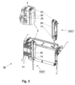
- the continuous casting mold 30 is shown partially dismantled for the purpose of a simplified representation. It can thus be seen how a strand guide device 10 can be attached to the continuous casting mold 30 .
- a strand guide device 10 is shown in such a way that its bolts 28 are located just above the holding devices 29 that are provided on the free ends of the respective adjustment elements 31 .
- a strand guide device 10 is shown in a state when it has been lifted out of the continuous casting mold 30 .
- figure 4 shows a perspective view of the continuous casting mold 30 of FIG 3 , now in a state when two strand guide devices 10 are attached or mounted to the adjusting devices 31 of the continuous casting mold 30.
- the bolts 28 are then engaged in the associated holding devices 29, resulting in a form-fitting attachment of the strand guide device 10 to the continuous casting mold 30.
- figure 5 shows another perspective view of the continuous casting mold 30, now in a state when both strand guide devices 10 are lifted up out of the continuous casting mold 30.
- a lifting of the strand guide devices 10 can be effected by attaching traction means to the ring eyes 30 and then pulling them upwards using a crane or the like.
- the 6 and 7 each show a perspective view of the continuous casting mold 30 of FIG 3 in a state when a front part 34 of the continuous casting mold 30 is mounted thereon.
- the strand guide devices 10 are shown in FIG 6 lifted out of the continuous casting mold 30 (in the same way as in figure 5 ), and in the representation of 7 used within the continuous casting mold.
- FIG 7 symbolized by the arrow "T".
- the strand guide devices 10 serve the strand guide devices 10, when they are mounted in the continuous casting mold 30, for the purpose of guiding a cast strand with a rectangular cross-section on its narrow side and supporting it appropriately.
- the guide rollers 14 of the strand guide devices 10 come into contact with the cast strand 12 immediately after the cast strand 12 has emerged from the continuous casting mold 30 .
- an edge region of the cast strand 12 with which the crowned-convex guide rollers 14 come into contact still has elastic properties.
- a strand guiding device 10 can also have a guide roller which is brought into contact with a longitudinal side of the cast strand 12 .
- a guide roller 15 also has a crowned, convex outer contour, as referred to above 1 explained, and serves to ensure that the introduction of a targeted concave embossing in the longitudinal side of the cast strand counteracts the tendency of the strand shell to bulge and thus compensates for such a bulging.
- the functioning of a guide roller 15, which is brought into contact with the longitudinal side of a cast strand corresponds, mutatis mutandis, to the functioning of a guide roller 14, which is set against the narrow side 12 of the cast strand 12.
- a strand guide device 10 for supporting a cast strand 12 with a rectangular cross section can have a plurality of guide rollers 14, 15 which are set against both the narrow side 22 of the cast strand 12 and the longitudinal side of the cast strand 12, namely at a point in time if the cast strand 12 still has elastic properties in areas close to the edge both on its narrow side and on its long side.
Landscapes
- Engineering & Computer Science (AREA)
- Mechanical Engineering (AREA)
- Continuous Casting (AREA)
- Guides For Winding Or Rewinding, Or Guides For Filamentary Materials (AREA)
Claims (2)
- Procédé destiné à supporter une barre de coulée (12) possédant une section transversale de forme rectangulaire, dans lequel au moins un rouleau de guidage (14) monté en rotation présente un contour externe convexe (18) avec une forme bombée, dans lequel le contour externe (18) du rouleau de guidage (14; 15) est formé par une courbe continue convexe vers l'extérieur sans point d'inflexion avec un ou plusieurs rayons de courbure, et le rouleau de guidage (14) vient se placer avec ce contour externe (18) contre un côté de la barre de coulée (12) tandis que la barre de coulée (12) présente, dans une zone proche du bord, encore des propriétés élastiques, dans lequel le plus grand diamètre (D_max) du contour externe (18) du rouleau de guidage (14; 15), par référence à un diamètre (D_min) du rouleau de guidage (14 ; 15) à son côté avant, prend, dans le rapport, au maximum la valeur 1.5 et au minimal la valeur 1,00, où l'on prévoit, dans la direction de transport (T) de la barre de coulée (12), plusieurs rouleaux de guidage (14) disposés à fleur les uns derrière les autres et placés de manière conjointe contre un côté de la barre de coulée (12) de forme rectangulaire; dans lequel, pour les rouleaux de guidage individuels (14) - dans le sens aval de la direction de transport (T) de la barre de coulée (12) - le bombement du contour externe (18) augmente d'une manière telle que le quotient du plus grand diamètre (D_max) du contour externe (18) d'un rouleau de guidage (14) au diamètre (D_min) du rouleau de guidage (14) croît à son côté avant.
- Procédé selon la revendication 1, caractérisé en ce que l'on prévoit plusieurs rouleaux de guidage (14; 15) montés en rotation, comprenant respectivement un contour externe convexe (18) avec une forme bombée ; dans lequel au moins un rouleau de guidage (14) est placé contre un petit côté (22) de la barre de coulée (12) ; et dans lequel au moins un rouleau de guidage supplémentaire (15) est placé contre un grand côté (22) de la barre de coulée (12).
Applications Claiming Priority (2)
| Application Number | Priority Date | Filing Date | Title |
|---|---|---|---|
| DE102016206454 | 2016-04-18 | ||
| DE102017200983.7A DE102017200983A1 (de) | 2016-04-18 | 2017-01-23 | Strangführungseinrichtung und Verfahren zum Stützen eines Gießstrangs |
Publications (3)
| Publication Number | Publication Date |
|---|---|
| EP3235579A1 EP3235579A1 (fr) | 2017-10-25 |
| EP3235579B1 EP3235579B1 (fr) | 2020-05-13 |
| EP3235579B2 true EP3235579B2 (fr) | 2023-08-30 |
Family
ID=58672280
Family Applications (1)
| Application Number | Title | Priority Date | Filing Date |
|---|---|---|---|
| EP17163459.5A Active EP3235579B2 (fr) | 2016-04-18 | 2017-03-29 | Dispositif de guidage de barre et procédé destiné à supporter une barre de coulée |
Country Status (1)
| Country | Link |
|---|---|
| EP (1) | EP3235579B2 (fr) |
Family Cites Families (11)
| Publication number | Priority date | Publication date | Assignee | Title |
|---|---|---|---|---|
| US3837392A (en) * | 1971-11-18 | 1974-09-24 | I Rossi | Apparatus for continuously casting steel slabs |
| US3900066A (en) | 1974-01-02 | 1975-08-19 | Allis Chalmers | Apparatus for continuous casting a metal strand shaped to provide concave surfaces |
| GB1596395A (en) | 1977-12-14 | 1981-08-26 | Jernkontoret Forskningsavdelni | Method of continuous casting of steels or metal alloys with segregation tendancy and apparatus for carrying out the method |
| DE3427708C2 (de) | 1984-07-27 | 1986-09-04 | Krupp Stahl Ag, 4630 Bochum | Vorrichtung zum seitlichen Führen eines Stranges einer Knüppel-Stranggießanlage |
| DE4403045C1 (de) * | 1994-01-28 | 1995-09-07 | Mannesmann Ag | Stranggießanlage zum Führen von Strängen |
| DE4403047C1 (de) * | 1994-01-28 | 1995-08-10 | Mannesmann Ag | Strangführungsgerüst |
| DE4403046C1 (de) | 1994-01-28 | 1995-08-17 | Mannesmann Ag | Rolle für ein Strangführungsgerüst |
| DE19520939C1 (de) | 1995-06-02 | 1996-07-25 | Mannesmann Ag | Verstelleinrichtung für Führungsrollen in Stranggießanlagen |
| DE10119550A1 (de) | 2001-04-21 | 2002-10-24 | Sms Demag Ag | Verfahren und Vorrichtung zum Herstellen von Stranggu-Vormaterial |
| JP2003094154A (ja) | 2001-09-21 | 2003-04-02 | Sanyo Special Steel Co Ltd | 鋼の連続鋳造方法 |
| KR101264635B1 (ko) | 2010-11-19 | 2013-05-24 | 주식회사 포스코 | 주편 압하 장치 및 이를 이용한 연속주조 방법 |
-
2017
- 2017-03-29 EP EP17163459.5A patent/EP3235579B2/fr active Active
Also Published As
| Publication number | Publication date |
|---|---|
| EP3235579B1 (fr) | 2020-05-13 |
| EP3235579A1 (fr) | 2017-10-25 |
Similar Documents
| Publication | Publication Date | Title |
|---|---|---|
| AT506549B1 (de) | Strangführungssegment | |
| DE2501956C2 (de) | Vorrichtung zum Stützen, Führen, Biegen bzw. Richten und Verformen eines breiten Gußstranges | |
| EP2056981A1 (fr) | Dispositif de guidage de barre et procédé de guidage d'un feuillard métallique encore non durci à c ur | |
| DE3132815A1 (de) | Verfahren und einrichtung zum geraderichten von stahlrohren und dergleichen | |
| DE4306853C2 (de) | Strangführungsgerüst | |
| DE102008009136A1 (de) | Strangführung, insbesondere für eine Stahlbrammen-Stranggießanlage | |
| DE2416625A1 (de) | Fuehrungswalzensegment fuer gusstuecke in einer stranggiesseinrichtung | |
| EP3235579B2 (fr) | Dispositif de guidage de barre et procédé destiné à supporter une barre de coulée | |
| DE10218779B4 (de) | Lagerung der beiden Walzen einer Walzenmühle | |
| EP3256276B1 (fr) | Installation de coulage | |
| DE102021207301A1 (de) | Strangführungseinrichtung und Verfahren zum Stranggießen eines metallischen Produkts in einer Stranggießanlage mit einer solchen Strangführungseinrichtung | |
| DE69924466T2 (de) | Abstreifvorrichtung für flüssigkeiten | |
| EP1313580B1 (fr) | Dispositif de coulee continue de metaux, notamment d'acier | |
| WO2006056423A1 (fr) | Dispositif et procede de coulee continue | |
| DE2731748B2 (de) | Rollenführungsgerüst für eine Stahlstranggießanlage | |
| DE69005049T2 (de) | Verfahren und Vorrichtung zum Stranggiessen mit Doppelrollen von dünnen metallischen Produkten, geeignet zum Kaltwalzen. | |
| WO2002090019A1 (fr) | Procede et dispositif permettant la coulee continue de blocs, de brames ou de brames minces | |
| DE102017200983A1 (de) | Strangführungseinrichtung und Verfahren zum Stützen eines Gießstrangs | |
| EP3097995B1 (fr) | Segment de guidage de bramme d'une installation de coulee continue et installation de coulee continue | |
| EP2648865B1 (fr) | Installation de coulée continue servant à couler une barre métallique | |
| EP4489928B1 (fr) | Segment arqué d'un dispositif de guidage de barre | |
| DE102022212862A1 (de) | Strangführungseinrichtung zum Stützen eines Gießstrangs | |
| DE102005038574A1 (de) | Walzgerüst und Walzvorrichtung zum Walzen eines Walzprodukts | |
| DE202012012284U1 (de) | Strangführung für eine Stranggießanlage | |
| CH620613A5 (en) | Roller guide for a continuous steel-casting installation |
Legal Events
| Date | Code | Title | Description |
|---|---|---|---|
| PUAI | Public reference made under article 153(3) epc to a published international application that has entered the european phase |
Free format text: ORIGINAL CODE: 0009012 |
|
| STAA | Information on the status of an ep patent application or granted ep patent |
Free format text: STATUS: EXAMINATION IS IN PROGRESS |
|
| 17P | Request for examination filed |
Effective date: 20170329 |
|
| AK | Designated contracting states |
Kind code of ref document: A1 Designated state(s): AL AT BE BG CH CY CZ DE DK EE ES FI FR GB GR HR HU IE IS IT LI LT LU LV MC MK MT NL NO PL PT RO RS SE SI SK SM TR |
|
| AX | Request for extension of the european patent |
Extension state: BA ME |
|
| RBV | Designated contracting states (corrected) |
Designated state(s): AL AT BE BG CH CY CZ DE DK EE ES FI FR GB GR HR HU IE IS IT LI LT LU LV MC MK MT NL NO PL PT RO RS SE SI SK SM TR |
|
| GRAP | Despatch of communication of intention to grant a patent |
Free format text: ORIGINAL CODE: EPIDOSNIGR1 |
|
| STAA | Information on the status of an ep patent application or granted ep patent |
Free format text: STATUS: GRANT OF PATENT IS INTENDED |
|
| INTG | Intention to grant announced |
Effective date: 20191122 |
|
| GRAS | Grant fee paid |
Free format text: ORIGINAL CODE: EPIDOSNIGR3 |
|
| TPAC | Observations filed by third parties |
Free format text: ORIGINAL CODE: EPIDOSNTIPA |
|
| GRAA | (expected) grant |
Free format text: ORIGINAL CODE: 0009210 |
|
| STAA | Information on the status of an ep patent application or granted ep patent |
Free format text: STATUS: THE PATENT HAS BEEN GRANTED |
|
| AK | Designated contracting states |
Kind code of ref document: B1 Designated state(s): AL AT BE BG CH CY CZ DE DK EE ES FI FR GB GR HR HU IE IS IT LI LT LU LV MC MK MT NL NO PL PT RO RS SE SI SK SM TR |
|
| REG | Reference to a national code |
Ref country code: GB Ref legal event code: FG4D Free format text: NOT ENGLISH |
|
| REG | Reference to a national code |
Ref country code: CH Ref legal event code: EP |
|
| REG | Reference to a national code |
Ref country code: DE Ref legal event code: R096 Ref document number: 502017005203 Country of ref document: DE |
|
| REG | Reference to a national code |
Ref country code: AT Ref legal event code: REF Ref document number: 1269595 Country of ref document: AT Kind code of ref document: T Effective date: 20200615 |
|
| REG | Reference to a national code |
Ref country code: LT Ref legal event code: MG4D |
|
| REG | Reference to a national code |
Ref country code: NL Ref legal event code: MP Effective date: 20200513 |
|
| PG25 | Lapsed in a contracting state [announced via postgrant information from national office to epo] |
Ref country code: IS Free format text: LAPSE BECAUSE OF FAILURE TO SUBMIT A TRANSLATION OF THE DESCRIPTION OR TO PAY THE FEE WITHIN THE PRESCRIBED TIME-LIMIT Effective date: 20200913 Ref country code: PT Free format text: LAPSE BECAUSE OF FAILURE TO SUBMIT A TRANSLATION OF THE DESCRIPTION OR TO PAY THE FEE WITHIN THE PRESCRIBED TIME-LIMIT Effective date: 20200914 Ref country code: FI Free format text: LAPSE BECAUSE OF FAILURE TO SUBMIT A TRANSLATION OF THE DESCRIPTION OR TO PAY THE FEE WITHIN THE PRESCRIBED TIME-LIMIT Effective date: 20200513 Ref country code: SE Free format text: LAPSE BECAUSE OF FAILURE TO SUBMIT A TRANSLATION OF THE DESCRIPTION OR TO PAY THE FEE WITHIN THE PRESCRIBED TIME-LIMIT Effective date: 20200513 Ref country code: LT Free format text: LAPSE BECAUSE OF FAILURE TO SUBMIT A TRANSLATION OF THE DESCRIPTION OR TO PAY THE FEE WITHIN THE PRESCRIBED TIME-LIMIT Effective date: 20200513 Ref country code: GR Free format text: LAPSE BECAUSE OF FAILURE TO SUBMIT A TRANSLATION OF THE DESCRIPTION OR TO PAY THE FEE WITHIN THE PRESCRIBED TIME-LIMIT Effective date: 20200814 Ref country code: NO Free format text: LAPSE BECAUSE OF FAILURE TO SUBMIT A TRANSLATION OF THE DESCRIPTION OR TO PAY THE FEE WITHIN THE PRESCRIBED TIME-LIMIT Effective date: 20200813 |
|
| PG25 | Lapsed in a contracting state [announced via postgrant information from national office to epo] |
Ref country code: BG Free format text: LAPSE BECAUSE OF FAILURE TO SUBMIT A TRANSLATION OF THE DESCRIPTION OR TO PAY THE FEE WITHIN THE PRESCRIBED TIME-LIMIT Effective date: 20200813 Ref country code: LV Free format text: LAPSE BECAUSE OF FAILURE TO SUBMIT A TRANSLATION OF THE DESCRIPTION OR TO PAY THE FEE WITHIN THE PRESCRIBED TIME-LIMIT Effective date: 20200513 Ref country code: RS Free format text: LAPSE BECAUSE OF FAILURE TO SUBMIT A TRANSLATION OF THE DESCRIPTION OR TO PAY THE FEE WITHIN THE PRESCRIBED TIME-LIMIT Effective date: 20200513 Ref country code: HR Free format text: LAPSE BECAUSE OF FAILURE TO SUBMIT A TRANSLATION OF THE DESCRIPTION OR TO PAY THE FEE WITHIN THE PRESCRIBED TIME-LIMIT Effective date: 20200513 |
|
| PG25 | Lapsed in a contracting state [announced via postgrant information from national office to epo] |
Ref country code: AL Free format text: LAPSE BECAUSE OF FAILURE TO SUBMIT A TRANSLATION OF THE DESCRIPTION OR TO PAY THE FEE WITHIN THE PRESCRIBED TIME-LIMIT Effective date: 20200513 Ref country code: NL Free format text: LAPSE BECAUSE OF FAILURE TO SUBMIT A TRANSLATION OF THE DESCRIPTION OR TO PAY THE FEE WITHIN THE PRESCRIBED TIME-LIMIT Effective date: 20200513 |
|
| PG25 | Lapsed in a contracting state [announced via postgrant information from national office to epo] |
Ref country code: EE Free format text: LAPSE BECAUSE OF FAILURE TO SUBMIT A TRANSLATION OF THE DESCRIPTION OR TO PAY THE FEE WITHIN THE PRESCRIBED TIME-LIMIT Effective date: 20200513 Ref country code: DK Free format text: LAPSE BECAUSE OF FAILURE TO SUBMIT A TRANSLATION OF THE DESCRIPTION OR TO PAY THE FEE WITHIN THE PRESCRIBED TIME-LIMIT Effective date: 20200513 Ref country code: ES Free format text: LAPSE BECAUSE OF FAILURE TO SUBMIT A TRANSLATION OF THE DESCRIPTION OR TO PAY THE FEE WITHIN THE PRESCRIBED TIME-LIMIT Effective date: 20200513 Ref country code: SM Free format text: LAPSE BECAUSE OF FAILURE TO SUBMIT A TRANSLATION OF THE DESCRIPTION OR TO PAY THE FEE WITHIN THE PRESCRIBED TIME-LIMIT Effective date: 20200513 Ref country code: RO Free format text: LAPSE BECAUSE OF FAILURE TO SUBMIT A TRANSLATION OF THE DESCRIPTION OR TO PAY THE FEE WITHIN THE PRESCRIBED TIME-LIMIT Effective date: 20200513 Ref country code: CZ Free format text: LAPSE BECAUSE OF FAILURE TO SUBMIT A TRANSLATION OF THE DESCRIPTION OR TO PAY THE FEE WITHIN THE PRESCRIBED TIME-LIMIT Effective date: 20200513 |
|
| REG | Reference to a national code |
Ref country code: DE Ref legal event code: R026 Ref document number: 502017005203 Country of ref document: DE |
|
| PLBI | Opposition filed |
Free format text: ORIGINAL CODE: 0009260 |
|
| PG25 | Lapsed in a contracting state [announced via postgrant information from national office to epo] |
Ref country code: PL Free format text: LAPSE BECAUSE OF FAILURE TO SUBMIT A TRANSLATION OF THE DESCRIPTION OR TO PAY THE FEE WITHIN THE PRESCRIBED TIME-LIMIT Effective date: 20200513 Ref country code: SK Free format text: LAPSE BECAUSE OF FAILURE TO SUBMIT A TRANSLATION OF THE DESCRIPTION OR TO PAY THE FEE WITHIN THE PRESCRIBED TIME-LIMIT Effective date: 20200513 |
|
| PLAX | Notice of opposition and request to file observation + time limit sent |
Free format text: ORIGINAL CODE: EPIDOSNOBS2 |
|
| 26 | Opposition filed |
Opponent name: PRIMETALS TECHNOLOGIES AUSTRIA GMBH Effective date: 20210211 |
|
| PG25 | Lapsed in a contracting state [announced via postgrant information from national office to epo] |
Ref country code: SI Free format text: LAPSE BECAUSE OF FAILURE TO SUBMIT A TRANSLATION OF THE DESCRIPTION OR TO PAY THE FEE WITHIN THE PRESCRIBED TIME-LIMIT Effective date: 20200513 |
|
| PLBB | Reply of patent proprietor to notice(s) of opposition received |
Free format text: ORIGINAL CODE: EPIDOSNOBS3 |
|
| PG25 | Lapsed in a contracting state [announced via postgrant information from national office to epo] |
Ref country code: MC Free format text: LAPSE BECAUSE OF FAILURE TO SUBMIT A TRANSLATION OF THE DESCRIPTION OR TO PAY THE FEE WITHIN THE PRESCRIBED TIME-LIMIT Effective date: 20200513 |
|
| REG | Reference to a national code |
Ref country code: CH Ref legal event code: PL |
|
| REG | Reference to a national code |
Ref country code: BE Ref legal event code: MM Effective date: 20210331 |
|
| PG25 | Lapsed in a contracting state [announced via postgrant information from national office to epo] |
Ref country code: CH Free format text: LAPSE BECAUSE OF NON-PAYMENT OF DUE FEES Effective date: 20210331 Ref country code: LU Free format text: LAPSE BECAUSE OF NON-PAYMENT OF DUE FEES Effective date: 20210329 Ref country code: LI Free format text: LAPSE BECAUSE OF NON-PAYMENT OF DUE FEES Effective date: 20210331 Ref country code: FR Free format text: LAPSE BECAUSE OF NON-PAYMENT OF DUE FEES Effective date: 20210331 Ref country code: IE Free format text: LAPSE BECAUSE OF NON-PAYMENT OF DUE FEES Effective date: 20210329 |
|
| PG25 | Lapsed in a contracting state [announced via postgrant information from national office to epo] |
Ref country code: BE Free format text: LAPSE BECAUSE OF NON-PAYMENT OF DUE FEES Effective date: 20210331 |
|
| PG25 | Lapsed in a contracting state [announced via postgrant information from national office to epo] |
Ref country code: HU Free format text: LAPSE BECAUSE OF FAILURE TO SUBMIT A TRANSLATION OF THE DESCRIPTION OR TO PAY THE FEE WITHIN THE PRESCRIBED TIME-LIMIT; INVALID AB INITIO Effective date: 20170329 |
|
| PG25 | Lapsed in a contracting state [announced via postgrant information from national office to epo] |
Ref country code: CY Free format text: LAPSE BECAUSE OF FAILURE TO SUBMIT A TRANSLATION OF THE DESCRIPTION OR TO PAY THE FEE WITHIN THE PRESCRIBED TIME-LIMIT Effective date: 20200513 |
|
| PUAH | Patent maintained in amended form |
Free format text: ORIGINAL CODE: 0009272 |
|
| STAA | Information on the status of an ep patent application or granted ep patent |
Free format text: STATUS: PATENT MAINTAINED AS AMENDED |
|
| P01 | Opt-out of the competence of the unified patent court (upc) registered |
Effective date: 20230707 |
|
| 27A | Patent maintained in amended form |
Effective date: 20230830 |
|
| AK | Designated contracting states |
Kind code of ref document: B2 Designated state(s): AL AT BE BG CH CY CZ DE DK EE ES FI FR GB GR HR HU IE IS IT LI LT LU LV MC MK MT NL NO PL PT RO RS SE SI SK SM TR |
|
| REG | Reference to a national code |
Ref country code: DE Ref legal event code: R102 Ref document number: 502017005203 Country of ref document: DE |
|
| PG25 | Lapsed in a contracting state [announced via postgrant information from national office to epo] |
Ref country code: MK Free format text: LAPSE BECAUSE OF FAILURE TO SUBMIT A TRANSLATION OF THE DESCRIPTION OR TO PAY THE FEE WITHIN THE PRESCRIBED TIME-LIMIT Effective date: 20200513 |
|
| PG25 | Lapsed in a contracting state [announced via postgrant information from national office to epo] |
Ref country code: TR Free format text: LAPSE BECAUSE OF FAILURE TO SUBMIT A TRANSLATION OF THE DESCRIPTION OR TO PAY THE FEE WITHIN THE PRESCRIBED TIME-LIMIT Effective date: 20200513 |
|
| PG25 | Lapsed in a contracting state [announced via postgrant information from national office to epo] |
Ref country code: MT Free format text: LAPSE BECAUSE OF FAILURE TO SUBMIT A TRANSLATION OF THE DESCRIPTION OR TO PAY THE FEE WITHIN THE PRESCRIBED TIME-LIMIT Effective date: 20200513 |
|
| PGFP | Annual fee paid to national office [announced via postgrant information from national office to epo] |
Ref country code: GB Payment date: 20260324 Year of fee payment: 10 |
|
| PGFP | Annual fee paid to national office [announced via postgrant information from national office to epo] |
Ref country code: DE Payment date: 20260319 Year of fee payment: 10 |
|
| PGFP | Annual fee paid to national office [announced via postgrant information from national office to epo] |
Ref country code: AT Payment date: 20260320 Year of fee payment: 10 |
|
| PGFP | Annual fee paid to national office [announced via postgrant information from national office to epo] |
Ref country code: IT Payment date: 20260324 Year of fee payment: 10 |