EP3235748B1 - Récipient pliable - Google Patents
Récipient pliable Download PDFInfo
- Publication number
- EP3235748B1 EP3235748B1 EP15869320.0A EP15869320A EP3235748B1 EP 3235748 B1 EP3235748 B1 EP 3235748B1 EP 15869320 A EP15869320 A EP 15869320A EP 3235748 B1 EP3235748 B1 EP 3235748B1
- Authority
- EP
- European Patent Office
- Prior art keywords
- elastic member
- base
- connector
- groove
- spring
- Prior art date
- Legal status (The legal status is an assumption and is not a legal conclusion. Google has not performed a legal analysis and makes no representation as to the accuracy of the status listed.)
- Active
Links
- 230000007246 mechanism Effects 0.000 claims description 36
- 238000000034 method Methods 0.000 claims description 8
- 230000008569 process Effects 0.000 claims description 8
- 238000004519 manufacturing process Methods 0.000 description 3
- 230000008901 benefit Effects 0.000 description 2
- 230000003111 delayed effect Effects 0.000 description 2
- 230000007306 turnover Effects 0.000 description 2
- 235000008331 Pinus X rigitaeda Nutrition 0.000 description 1
- 235000011613 Pinus brutia Nutrition 0.000 description 1
- 241000018646 Pinus brutia Species 0.000 description 1
- 230000009471 action Effects 0.000 description 1
- 230000000694 effects Effects 0.000 description 1
- 230000005484 gravity Effects 0.000 description 1
- 230000002452 interceptive effect Effects 0.000 description 1
- 239000000463 material Substances 0.000 description 1
- 230000004048 modification Effects 0.000 description 1
- 238000012986 modification Methods 0.000 description 1
- 238000005381 potential energy Methods 0.000 description 1
- 230000007704 transition Effects 0.000 description 1
Images





Classifications
-
- B—PERFORMING OPERATIONS; TRANSPORTING
- B65—CONVEYING; PACKING; STORING; HANDLING THIN OR FILAMENTARY MATERIAL
- B65D—CONTAINERS FOR STORAGE OR TRANSPORT OF ARTICLES OR MATERIALS, e.g. BAGS, BARRELS, BOTTLES, BOXES, CANS, CARTONS, CRATES, DRUMS, JARS, TANKS, HOPPERS, FORWARDING CONTAINERS; ACCESSORIES, CLOSURES, OR FITTINGS THEREFOR; PACKAGING ELEMENTS; PACKAGES
- B65D19/00—Pallets or like platforms, with or without side walls, for supporting loads to be lifted or lowered
- B65D19/02—Rigid pallets with side walls, e.g. box pallets
- B65D19/06—Rigid pallets with side walls, e.g. box pallets with bodies formed by uniting or interconnecting two or more components
- B65D19/18—Rigid pallets with side walls, e.g. box pallets with bodies formed by uniting or interconnecting two or more components made wholly or mainly of plastics material
-
- B—PERFORMING OPERATIONS; TRANSPORTING
- B65—CONVEYING; PACKING; STORING; HANDLING THIN OR FILAMENTARY MATERIAL
- B65D—CONTAINERS FOR STORAGE OR TRANSPORT OF ARTICLES OR MATERIALS, e.g. BAGS, BARRELS, BOTTLES, BOXES, CANS, CARTONS, CRATES, DRUMS, JARS, TANKS, HOPPERS, FORWARDING CONTAINERS; ACCESSORIES, CLOSURES, OR FITTINGS THEREFOR; PACKAGING ELEMENTS; PACKAGES
- B65D88/00—Large containers
- B65D88/52—Large containers collapsible, i.e. with walls hinged together or detachably connected
- B65D88/522—Large containers collapsible, i.e. with walls hinged together or detachably connected all side walls hingedly connected to each other or to another component of the container
-
- B—PERFORMING OPERATIONS; TRANSPORTING
- B65—CONVEYING; PACKING; STORING; HANDLING THIN OR FILAMENTARY MATERIAL
- B65D—CONTAINERS FOR STORAGE OR TRANSPORT OF ARTICLES OR MATERIALS, e.g. BAGS, BARRELS, BOTTLES, BOXES, CANS, CARTONS, CRATES, DRUMS, JARS, TANKS, HOPPERS, FORWARDING CONTAINERS; ACCESSORIES, CLOSURES, OR FITTINGS THEREFOR; PACKAGING ELEMENTS; PACKAGES
- B65D11/00—Containers having bodies formed by interconnecting or uniting two or more rigid, or substantially rigid, components made wholly or mainly of plastics material
- B65D11/18—Containers having bodies formed by interconnecting or uniting two or more rigid, or substantially rigid, components made wholly or mainly of plastics material collapsible, i.e. with walls hinged together or detachably connected
- B65D11/1833—Containers having bodies formed by interconnecting or uniting two or more rigid, or substantially rigid, components made wholly or mainly of plastics material collapsible, i.e. with walls hinged together or detachably connected whereby all side walls are hingedly connected to the base panel
-
- B—PERFORMING OPERATIONS; TRANSPORTING
- B65—CONVEYING; PACKING; STORING; HANDLING THIN OR FILAMENTARY MATERIAL
- B65D—CONTAINERS FOR STORAGE OR TRANSPORT OF ARTICLES OR MATERIALS, e.g. BAGS, BARRELS, BOTTLES, BOXES, CANS, CARTONS, CRATES, DRUMS, JARS, TANKS, HOPPERS, FORWARDING CONTAINERS; ACCESSORIES, CLOSURES, OR FITTINGS THEREFOR; PACKAGING ELEMENTS; PACKAGES
- B65D2519/00—Pallets or like platforms, with or without side walls, for supporting loads to be lifted or lowered
- B65D2519/00004—Details relating to pallets
- B65D2519/00009—Materials
- B65D2519/00014—Materials for the load supporting surface
- B65D2519/00034—Plastic
-
- B—PERFORMING OPERATIONS; TRANSPORTING
- B65—CONVEYING; PACKING; STORING; HANDLING THIN OR FILAMENTARY MATERIAL
- B65D—CONTAINERS FOR STORAGE OR TRANSPORT OF ARTICLES OR MATERIALS, e.g. BAGS, BARRELS, BOTTLES, BOXES, CANS, CARTONS, CRATES, DRUMS, JARS, TANKS, HOPPERS, FORWARDING CONTAINERS; ACCESSORIES, CLOSURES, OR FITTINGS THEREFOR; PACKAGING ELEMENTS; PACKAGES
- B65D2519/00—Pallets or like platforms, with or without side walls, for supporting loads to be lifted or lowered
- B65D2519/00004—Details relating to pallets
- B65D2519/00009—Materials
- B65D2519/00049—Materials for the base surface
- B65D2519/00069—Plastic
-
- B—PERFORMING OPERATIONS; TRANSPORTING
- B65—CONVEYING; PACKING; STORING; HANDLING THIN OR FILAMENTARY MATERIAL
- B65D—CONTAINERS FOR STORAGE OR TRANSPORT OF ARTICLES OR MATERIALS, e.g. BAGS, BARRELS, BOTTLES, BOXES, CANS, CARTONS, CRATES, DRUMS, JARS, TANKS, HOPPERS, FORWARDING CONTAINERS; ACCESSORIES, CLOSURES, OR FITTINGS THEREFOR; PACKAGING ELEMENTS; PACKAGES
- B65D2519/00—Pallets or like platforms, with or without side walls, for supporting loads to be lifted or lowered
- B65D2519/00004—Details relating to pallets
- B65D2519/00009—Materials
- B65D2519/00154—Materials for the side walls
- B65D2519/00174—Plastic
-
- B—PERFORMING OPERATIONS; TRANSPORTING
- B65—CONVEYING; PACKING; STORING; HANDLING THIN OR FILAMENTARY MATERIAL
- B65D—CONTAINERS FOR STORAGE OR TRANSPORT OF ARTICLES OR MATERIALS, e.g. BAGS, BARRELS, BOTTLES, BOXES, CANS, CARTONS, CRATES, DRUMS, JARS, TANKS, HOPPERS, FORWARDING CONTAINERS; ACCESSORIES, CLOSURES, OR FITTINGS THEREFOR; PACKAGING ELEMENTS; PACKAGES
- B65D2519/00—Pallets or like platforms, with or without side walls, for supporting loads to be lifted or lowered
- B65D2519/00004—Details relating to pallets
- B65D2519/00258—Overall construction
- B65D2519/00313—Overall construction of the base surface
- B65D2519/00318—Overall construction of the base surface made of one piece
-
- B—PERFORMING OPERATIONS; TRANSPORTING
- B65—CONVEYING; PACKING; STORING; HANDLING THIN OR FILAMENTARY MATERIAL
- B65D—CONTAINERS FOR STORAGE OR TRANSPORT OF ARTICLES OR MATERIALS, e.g. BAGS, BARRELS, BOTTLES, BOXES, CANS, CARTONS, CRATES, DRUMS, JARS, TANKS, HOPPERS, FORWARDING CONTAINERS; ACCESSORIES, CLOSURES, OR FITTINGS THEREFOR; PACKAGING ELEMENTS; PACKAGES
- B65D2519/00—Pallets or like platforms, with or without side walls, for supporting loads to be lifted or lowered
- B65D2519/00004—Details relating to pallets
- B65D2519/00258—Overall construction
- B65D2519/00313—Overall construction of the base surface
- B65D2519/00328—Overall construction of the base surface shape of the contact surface of the base
- B65D2519/00333—Overall construction of the base surface shape of the contact surface of the base contact surface having a stringer-like shape
-
- B—PERFORMING OPERATIONS; TRANSPORTING
- B65—CONVEYING; PACKING; STORING; HANDLING THIN OR FILAMENTARY MATERIAL
- B65D—CONTAINERS FOR STORAGE OR TRANSPORT OF ARTICLES OR MATERIALS, e.g. BAGS, BARRELS, BOTTLES, BOXES, CANS, CARTONS, CRATES, DRUMS, JARS, TANKS, HOPPERS, FORWARDING CONTAINERS; ACCESSORIES, CLOSURES, OR FITTINGS THEREFOR; PACKAGING ELEMENTS; PACKAGES
- B65D2519/00—Pallets or like platforms, with or without side walls, for supporting loads to be lifted or lowered
- B65D2519/00004—Details relating to pallets
- B65D2519/00258—Overall construction
- B65D2519/00492—Overall construction of the side walls
- B65D2519/00497—Overall construction of the side walls whereby at least one side wall is made of one piece
-
- B—PERFORMING OPERATIONS; TRANSPORTING
- B65—CONVEYING; PACKING; STORING; HANDLING THIN OR FILAMENTARY MATERIAL
- B65D—CONTAINERS FOR STORAGE OR TRANSPORT OF ARTICLES OR MATERIALS, e.g. BAGS, BARRELS, BOTTLES, BOXES, CANS, CARTONS, CRATES, DRUMS, JARS, TANKS, HOPPERS, FORWARDING CONTAINERS; ACCESSORIES, CLOSURES, OR FITTINGS THEREFOR; PACKAGING ELEMENTS; PACKAGES
- B65D2519/00—Pallets or like platforms, with or without side walls, for supporting loads to be lifted or lowered
- B65D2519/00004—Details relating to pallets
- B65D2519/00547—Connections
- B65D2519/00577—Connections structures connecting side walls, including corner posts, to each other
- B65D2519/00582—Connections structures connecting side walls, including corner posts, to each other structures intended to be disassembled, i.e. collapsible or dismountable
- B65D2519/00611—Connections structures connecting side walls, including corner posts, to each other structures intended to be disassembled, i.e. collapsible or dismountable side walls maintained connected to each other by means of auxiliary locking elements, e.g. spring loaded locking pins
-
- B—PERFORMING OPERATIONS; TRANSPORTING
- B65—CONVEYING; PACKING; STORING; HANDLING THIN OR FILAMENTARY MATERIAL
- B65D—CONTAINERS FOR STORAGE OR TRANSPORT OF ARTICLES OR MATERIALS, e.g. BAGS, BARRELS, BOTTLES, BOXES, CANS, CARTONS, CRATES, DRUMS, JARS, TANKS, HOPPERS, FORWARDING CONTAINERS; ACCESSORIES, CLOSURES, OR FITTINGS THEREFOR; PACKAGING ELEMENTS; PACKAGES
- B65D2519/00—Pallets or like platforms, with or without side walls, for supporting loads to be lifted or lowered
- B65D2519/00004—Details relating to pallets
- B65D2519/00547—Connections
- B65D2519/00636—Connections structures connecting side walls to the pallet
- B65D2519/00641—Structures intended to be disassembled
- B65D2519/00646—Structures intended to be disassembled by means of hinges
- B65D2519/00656—Structures intended to be disassembled by means of hinges separately formed
-
- B—PERFORMING OPERATIONS; TRANSPORTING
- B65—CONVEYING; PACKING; STORING; HANDLING THIN OR FILAMENTARY MATERIAL
- B65D—CONTAINERS FOR STORAGE OR TRANSPORT OF ARTICLES OR MATERIALS, e.g. BAGS, BARRELS, BOTTLES, BOXES, CANS, CARTONS, CRATES, DRUMS, JARS, TANKS, HOPPERS, FORWARDING CONTAINERS; ACCESSORIES, CLOSURES, OR FITTINGS THEREFOR; PACKAGING ELEMENTS; PACKAGES
- B65D2519/00—Pallets or like platforms, with or without side walls, for supporting loads to be lifted or lowered
- B65D2519/00004—Details relating to pallets
- B65D2519/00736—Details
- B65D2519/00865—Collapsible, i.e. at least two constitutive elements remaining hingedly connected
- B65D2519/00875—Collapsible, i.e. at least two constitutive elements remaining hingedly connected collapsible side walls
- B65D2519/009—Collapsible, i.e. at least two constitutive elements remaining hingedly connected collapsible side walls whereby all side walls are hingedly connected to the base panel
Definitions
- the present invention relates to a container, in particular, a foldable container, such as a turnover box.
- the current plastic large-sized foldable container is mostly composed of a base and two pairs of side plates, which are connected to the base by a hinge mechanism so that each side plate can be rotated relative to the base then be folded to the base.
- one pair of the side plates is longer and the other is shorter, and an optional side plate can be provided with a small door.
- the hinge mechanism is often designed such that the side plates can be folded disorderly, i.e., the two opposite side plates can be folded in any order at the time of folding so that user is not necessary to consider about the order of folding when folding the side plates, and the folding action would be accomplished no matter which one of the opposite side plates is folded first. Therefore, the hinge mechanism is also referred to as a disordered hinge.
- the container comprises a base and two pairs of lateral plates, wherein the lateral plates are provided with one or more movable parts extending from the lower portions of the lateral plates, one or more open lateral parts are arranged on the base, the lateral plates are placed in the corresponding open lateral parts on the base through the movable parts, and hinge devices are arranged between the movable parts and the open lateral parts; each hinge device comprises hinge holes formed in the movable parts of the corresponding lateral plate, a guiding device arranged in the corresponding open lateral part of the base, and a connecting piece provided with hinge pines and a sliding device matched with the guiding device, wherein the sliding device on the connecting piece can move vertically along the guiding device in the open lateral part, and the hinge pins are placed in the hinge holes and can rotate in the hinge holes.
- the lateral plates do not incline after the container is folded. Furthermore, the foldable container can achieve tool-free dismounting and unordered folding.
- US5755472A discloses a platform based shipping container with folding endwalls which enable the empty container to be stacked up with a pile of similar folded container for economical transport. There is a twistlock at each corner to interlock folded containers together and a top lift aperture at each corner to enable the pile to be lifted from above. At least one endwall can also fold outwardly away from the base to provide a ramp for the loading of vehicles. The endwalls are resiliently biased to provide for folding in either direction.
- the applicant have found that there is a drawback to the above disordered hinge mechanism that after the opposite side plates using the disordered hinges are folded, the later folded side plate lies on the first folded side plate, and the hinge mechanism is lifted by a height.
- the hinge portion of the side plate placed at the top is required to fall to the beginning position on the base during rotation from the lying position to the upright position. If the upper side plate overturns to upright or near the upright but the hinge portion is not fully fallen, some of the structures on the side plate, such as the latch of the side plate engaging with the base, would interfere with the base, and the hinge mechanism of the side plate or parts of the base may be damaged.
- the object of the present invention is to solve the problem that the hinge of the side plates are delayed falling when the side plate overturns from the folded state to the upright state in the foldable container.
- the present invention provides a foldable container according to claim 1 and, alternatively, a foldable container according to claim 11.
- a foldable container comprises a base and two pairs of side plates, the side plates are mounted on the base by means of a hinge mechanism in a manner of being foldable relative to the base, wherein the hinge mechanism comprises: one or more projecting portions extending from bottom of the side plates and provided with a hinge pin mounting portion, one or more open side portion provided on the base for cooperating with the projecting portion and provided with a guide structure; a connector being movable up and down along the guide structure and provided with a hinge pin for engaging with the hinge pin mounting portion, wherein the hinge pin is rotatably housed in the hinge pin mounting portion, and an elastic member with one end connected to the base and the other end connected to the connector, so that the elastic member applies force to the connector during rotation process of the side plates from folded state to upright state so as to drive the connector to move downwardly.
- the hinge mechanism comprises: one or more projecting portions extending from bottom of the side plates and provided with a hinge pin mounting portion, one or more open side portion provided on the base for cooperating with the projecting portion and
- the elastic member is compressed when the side plates are in compressed station.
- the guide structure is provided with an elastic member housing slot and the elastic member is housed in the elastic member housing slot, and upper end of the elastic member is connected to the base and lower end of the elastic member is connected to the connector.
- the elastic member is a spring
- the guide structure includes a spring housing slot and the spring is housed in the spring housing slot, and the upper end of the spring is defined by the cover plates which are fixed on the base and lower end is connected to the connector.
- the guide structure is a straight column provided on open side portion, and an elastic member housing slot is provided in the straight column, and the elastic member is housed in the elastic housing slot; and the hinge pin is provided on outer side of the connector, and the center of the connector is provided with a through groove along height direction of the container, and an elastic mounting post is provided in the through groove, wherein the through groove of the connector is sleeved in the straight column and the elastic member mounting column is connected to the lower end of the elastic member and the upper end of the elastic member is blocked by the cover plate located on the through groove.
- the projecting portion is provided with a groove for avoiding the straight groove.
- both sides of upper portion of the straight column is provided with a groove and the cover plate is provided with a hanging projection, and the hanging projection is inserted into the groove so that the cover plate is connected to the straight column and the upper end of the elastic member abuts against the bottom of the cover plate.
- the hinge pin includes a straight gap
- the hinge pin mounting portion is an opening groove with a boss provided on mouth, so that tthe mouth of the opening groove has a width smaller than the diameter of the hinge pin and longer than width of the portion of the hinge pin provided with the straight gap.
- the guide structure is a guide groove provided on both sides of the open side portion, and the elastic member is housed in in the guide groove; and the middle portion of the connector is the hinge pin, and both ends of the connector are respectively provided with the elastic member connecting portion for housing the guide groove on both sides of the open side portion, wherein upper end of the elastic member is blocked by the cover plate and lower end of the elastic member is connected to the elastic member connecting portion.
- the elastic member is a spring
- a sliding lug is extended from both ends of the connector
- the elastic member mounting portion is a cam pin provided on the sliding lug, and lower end of the spring is sleeved on the cam pin.
- both sides of the projecting portion is provided with a hanging projection respectively
- the base is provided with a hanging groove
- the hanging projection is engaged with the hanging groove so as to block side plate to move up and down relative to the base in upright state.
- a foldable container comprising a base and two pairs of side plates, the side plates are mounted on the base by means of a hinge mechanism in the manner of being foldable relative to the base, wherein the hinge mechanism comprises:
- the open side portion is provided with an elastic member housing slot and the elastic member is housed in the elastic member housing slot, and upper end of the elastic member is connected to the projecting portion and lower end is secured in the elastic member housing slot.
- the hinge pin is provided on one side or both sides of the projecting portion, and middle portion of the projecting portion is provided with a hanging pin;
- the elastic member is a spring, and one end of the spring has a hook; wherein one end of the spring is secured in the elastic housing groove, and other end with the hook is connected to the hanging pin.
- the invention solves the delay in the falling of the hinge mounted on the side plates of the large-sized container and is well suited to the operating habits of the various users, and the structure is novel and the idea is ingenious.
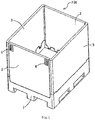
- general foldable large-sized containers comprises a base 1 and two pairs of side plates 2, 3, and each side plate is mounted on the base 1 by means of a hinge mechanism in manner of being foldable relative to the base 1.
- a latch 4 is generally provided on the side plate 2 for controlling connection between the adjacent side plates 2 and 3, so as to complete the transition of the side plates 2, 3 between folded state and upright state.
- the side plates 2, 3 may have a small door (not shown), and optionally a lid (not shown) is placed at the top of the container.
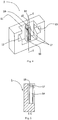
- Figs. 2 ⁇ 12 show a hinge mechanism 100 according to a first embodiment of the present invention.
- the hinge mechanism comprises: one or more projecting portion 31 extending from the bottom portion of the side plate 3 and being provided with a hinge pin mounting portion 35, in particular a hinge groove 35; an open side portion 11 provided on the base 1 and cooperating with the projecting portion 31, wherein the open side portion 11 has a guide structure 14, in particular a straight column 14; a connector 5 which can move up and down along the column 14 so that the connector 5 can move up and down relative to the base 1, and the connector 5 has a hinge pin 51 which engages with the hinge groove 35, and the hinge pin 51 is housed and rotatable in the hinge groove 35 so that the side plate 3 can be mounted rotatablelyon the connector 5; and an elastic member 8, in particular a spring 8, one end of which is connected to the base 1 and the other end is connected to the connector 5, specifically, the upper end of the spring 8 abuts against the cover plate 6,
- a tamper-evident piece 7 can be inserted between the cover plate 6 and the base so as to prevent the side plate from being removed without being perceived.
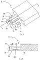
- Figures 4 and 5 show the structure associated with the hinge mechanism of the base 1.
- the base 1 has an open side portion 11 and two hanging grooves 12, 13 on both sides of the open side portion 11.
- the middle portion of the open side portion 11 is provided with a straight post 14, in the center of which is provided with a spring groove 15 for accommodating the spring 8.
- a rib18 is connected between the straight post 14 and the base 1 to ensure the strength of the straight post 14.
- Both sides of the upper portion of straight post 14 is provided with a slot 17 and a groove 19 for cooperating with the cover plate 6 to secure the cover plate, which will be further described below in detail.
- FIGS. 6 and 7 show the structure associated with the hinge mechanism on the side plate 3.
- a projecting portion 31 is provided on the bottom of side plate.
- On both sides of the projecting portion 3 is provided with hanging projections 32, 33 to cooperate with the hanging grooves 12 and 13 of the base 1, so as to restrict the vertical movement of the side plate 3 relative to the base 1 in upright state.
- the middle portion of the projecting portion 31 is provided with a recess 34 for avoiding the straight column 14 and a recess 36 for receiving the connector 5.
- Both sides of the recess 36 is provided with a hinge grooves 35, and the mouth portion of the hinge groove is provided with a small boss 37, so that the mouth of the hinge groove 35 has a width dx.
- the structure of the connector 5 is shown in Figure 8 .
- Two hinge pins 51 are provided on both sides of the connector body respectively.
- the hinge pins 51 have a straight gap 55 at a certain angle (during rotation of the side plates, the hinge pin would not be rotated to the certain angle, so that the hinge pin would not escape from the hinge slot or hinge hole during the rotation), so that the hinge pin 51 has a width dy slightly shorter than the width dx. In such way, only at the certain angle, can the connector 5 be installed in the hinge groove 35 of the side plate 3.
- the above small boss 37 and straight gap 55 is provided to prevent the hinge pin from escaping from the hinge hole or hinge slot during rotation.
- any other suitable structure known in the art may also be employed for achieving the same purpose.
- the middle portion of the connector 5 is a through groove 52 for passing through the straight column 14 of the base 1 and the through groove 52 can move up and down for a certain distance along the straight column 14.
- the middle of the through groove 52 is provide with a spring mounting post 53 for mounting the spring 8, with a chamfer 56 to increase connection strength of the spring mounting post 53 and the body of the connector 5 and with a slot 54 to avoid the rib 18 of the base 1.
- Figure 9 shows the detailed structure of the cover plate 6, which extends inwardly and forms two hanging projections 62.
- the hanging projection 62 has a position limiting projection 63 on the beginning end inserting into the slot 17 of the base la guiding bevel 64.
- the cover plate 6 is further provided with a slot 61 which can cooperate with a flat-blade screwdriver tool.
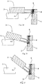
- Figs.10 ⁇ 12 The operation of the hinge mechanism of the present embodiment is shown in Figs.10 ⁇ 12 .
- one of the two opposite side plates 3 later folded is laid on the other firstly folded, and the hinge portion of the one later folded is raised by a distance equal to about the thickness of one side plate, when the spring 8 is compressed to be in charge state but its strength is insufficient to lift the side plate 3 with a point pi as fulcrum.
- the first side plate 3 is rotated to upright, there may be two fulcrums depending on the different operation habits: one is the fulcrum pi, the other is the hinge pin 51 of the connector 5.
- the hinge mechanism When the side plate 3 is rotated with the point pi as the fulcrum, the hinge mechanism would automatically move down by a certain distance along the straight column 14 of the base 1. When the side plate 3 is rotated around the hinge pin 51, the side plate 3 placed above would be moved away from the fulcrum pi during the rotation, where the spring 8 releases its potential energy to push the hinge mechanism moving down along the straight column 14.
- the spring is placed above the connector, i.e., the upper portion of the spring is connected to the base, and the lower portion is connected to the connector 5, so that the spring is compressed when the foldable container is in foldable state, and the compressed spring is gradually released during the process that the side plate is rotated from the folded state to the upright state, thereby applying a downward pressure to the connector to drive the connector to move downwardly.
- the spring (or the other elastic member) may also be placed under the connector, i.e., the upper portion of the spring is connected to the connector, and the lower portion is connected to the base, so that the spring is stretched when the foldable container is folded and the spring is retracted during the process that the side plate is rotated from the folded state to the upright state, thereby applying the upward force to the connector so as to drive the connector to move downwardly.
- Figs.13 ⁇ 17 show the hinge mechanism 200 according to the second embodiment of the present invention.
- the hinge mechanism 200 of the embodiment is provided with two springs 8 for resetting the hinge mechanism, and the cover plate 9 is secured by screw, which slightly increase the mounting difficulty, but appropriately reduce the difficulty of manufacturing parts.
- the base 1 has an open side portion 11, which has guide grooves 15 provided on both sides, so that the connector 1a can move up and down for a certain distance along the groove.
- a screw hole 19 for mounting screw 10 is provided next to the guide groove 15, and hanging grooves 12, 13 are distributed on both sides of the open side portion 11.
- the projecting portion 31 of the side plate 3 is provided with hinge slot 35, and the mouth portion of the hinge slot 35 is provided with a small boss 37 with the same function as in the above-described embodiment, and the hanging projections 32 are distributed on both sides of the projecting portion 31.
- the body of the connector 1a is a level pin 1a1, and both ends of the level pin 1a1 are provided with a sliding lug 1a3 with a cam pin 1a4 serving as a spring mount.
- the spring 18 can be mounted on the sliding lug 1a3 which can move up and down in the guide groove 15. Similar to the first embodiment, the level pin 1a1 has a vertical notch ia2 so that only when the side plate 3 is in the folded laying state would the connector be inserted into the hinge groove 35.
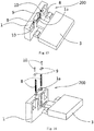
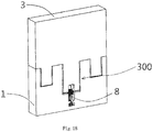
- Figs. 18 ⁇ 21 show the structure of the hinge mechanism 300 of the foldable container according to the third embodiment of the present invention.
- the present embodiment is similar to the second embodiment, the main difference between them is in this embodiment, the connector is integrally formed with the projecting portion of the side plate, and meanwhile tension spring 8 is used as the elastic member.
- One end of the tension spring 8 is connected to the base, and the other end is connected to the projecting portion so that the tension spring 8 will apply a pulling force to the projecting portion 31 during the rotation of the side plate from the folded state to upright state, so as to drive the projecting portion 31 to move downwardly.
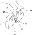
- the hanging projections 32, 33 are provided on both sides of the projecting portion 31 of the side plate 3, and the hanging grooves 12 and 13are provided on both sides of the groove of the base.
- the guide groove 15 is provided on both side surfaces on the groove of the base.
- the screw hole 19 for mounting the cover plate (similar to the cover plate 9 in Figure 14 ) is provided on the mouth portion of the guide groove.
- the mounted cover plate can limit the distance of the side plate hinge pin 38 floating in the guide groove to prevent it from coming off.
- a hanging pin 39 for connecting the hook 81 of the tension spring 8 is provided under the middle of the projecting portion 31 of the side plate, so as to make one end of the tension spring connect to the projecting portion.
- a slot 20 for housing the tension spring is provided at the bottom portion of the base recess 11.
- the slot 20 has a boss to connect and limit the other end 82 of the tension spring. In such way, the tension spring can quickly bring the side plate back to its position when the side plate float above the straight groove after being folded.
- the hinge mechanism of the present invention use elastic reset structure and thus allows that during the rotation of the side plate from the folded state to the upright state the connector of the hinge mechanism is forced to move downwardly, thereby driving the side plate which is connected to the connector to move downwardly, so as to solving the problem of damage to parts caused by the late drop of the side plate hinge.
- drop of the hinge would not be delayed no matter how the operators operate, where the center of gravity is and how the tolerance mates between the hinge of the side plate and the base, and thereby completely solving the problem of accidental damage of the container during the rotation of the side plate from the folded state to upright state.
- the present invention is particularly suitable for the large-sized container, in particular the large-sized foldable turnover boxes.
- the large-sized container herein refers to the container with a capacity of more than 800 L.
Landscapes
- Engineering & Computer Science (AREA)
- Mechanical Engineering (AREA)
- Rigid Containers With Two Or More Constituent Elements (AREA)
- Containers And Packaging Bodies Having A Special Means To Remove Contents (AREA)
- Closures For Containers (AREA)
Claims (13)
- Un conteneur repliable comprenant une base (1) et deux paires de plaques latérales (2, 3), les plaques latérales (2, 3) étant montées sur la base (1) au moyen d'un mécanisme à charnière (100, 200) de manière à pouvoir être repliées par rapport à la base (1), le mécanisme à charnière (100, 200) comprenant : une ou plusieurs parties saillantes (31), une ou plusieurs parties latérales ouvertes (11), un connecteur (5, 1a), dans lequel :les une ou plusieurs parties saillantes (31) s'étendent à partir d'un fond des plaques latérales (3) et sont pourvues d'une partie de montage à broche de charnière (35), les une ou plusieurs parties latérales ouvertes (11) sont prévues sur la base (1) pour coopérer avec la partie saillante (31) et pourvues d'une structure de guidage (14), le connecteur (5, 1a) est mobile vers le haut et vers le bas le long de la structure de guidage (14) et est pourvu d'une broche de charnière (51, 1a, 1) pour s'emboîter avec la partie de montage de broche de charnière (35),dans lequel la broche de charnière (51, 1a, 1) est logée à rotation dans la partie de montage de broche de charnière (35),caractérisé en ce quele mécanisme de charnière comprend en outre un organe élastique (8) avec une extrémité reliée à la base (1) et une autre extrémité reliée au connecteur (5, 1a), de sorte que l'organe élastique (8) applique une force au connecteur (5, 1a) durant le processus de rotation des plaques latérales d'un état replié à un état redressé de manière à entraîner le connecteur (5, 1a) en déplacement vers le bas.
- Le conteneur repliable selon la revendication 1, dans lequel la structure de guidage (14) est pourvue d'une fente de logement d'organe élastique et l'organe élastique (8) est logé dans la fente de logement d'organe élastique, et une extrémité supérieure de l'organe élastique (8) est reliée à la base (1) et une extrémité inférieure de l'organe élastique est reliée au connecteur (5, 1a).
- Le conteneur repliable selon la revendication 1, dans lequel l'organe élastique (8) est un ressort (8), et la structure de guidage (14) comprend une fente de logement de ressort et le ressort est logé dans la fente de logement de ressort, et une extrémité supérieure du ressort est bloquée par une plaque de fermeture (6, 9) qui est fixée sur la base (1) et une extrémité inférieure est reliée au connecteur (5, 1a).
- Le conteneur repliable selon la revendication 1, dans lequel la structure de guidage (14) est une colonne droite (14) disposée sur la partie latérale ouverte (11), et une fente de logement d'organe élastique est disposée dans la colonne droite (14), et l'organe élastique (8) est logé dans la fente de logement d'organe élastique ; et la broche de charnière (51) est disposée sur un côté externe du connecteur (5) et le centre du connecteur (5) est pourvu d'une gorge traversante (52) le long d'une direction en hauteur du conteneur, et un montant de montage élastique est disposé dans la gorge traversante (52), la gorge traversante (52) du connecteur (5) étant manchonnée dans la colonne droite (14) et la colonne de montage d'organe élastique étant reliée à une extrémité inférieure de l'organe élastique (8) et une extrémité supérieure de l'organe élastique (8) étant bloquée par une plaque de fermeture (6) située sur la gorge traversante (52).
- Le conteneur pliable selon la revendication 4, dans lequel des nervures (18) relient la colonne droite (14) à la base (1).
- Le conteneur pliable selon la revendication 4, dans lequel les deux côtés d'une partie supérieure de la colonne droite (14) sont pourvus d'une gorge et la plaque de fermeture (6) est pourvue d'une saillie d'accrochage (32, 33), et la saillie d'accrochage (32, 33) est insérée dans la gorge de sorte que la plaque de fermeture (6) soit reliée à la colonne droite (14) et l'extrémité supérieure de l'organe élastique (8) vienne en appui contre un fond de la plaque de fermeture (6).
- Le conteneur repliable selon la revendication 4, dans lequel la broche de charnière (51) comprend un intervalle droit (55), et la partie de montage de broche de charnière (35) est une gorge ouvrante avec un bossage (37) prévu sur une embouchure de la gorge ouvrante, de sorte que l'embouchure de la gorge ouvrante présente une largeur plus courte que le diamètre de la broche de charnière (51) et plus longue qu'une largeur de la partie de la broche de charnière (51) prévue avec l'intervalle droit (55).
- Le conteneur repliable selon la revendication 1, dans lequel la structure de guidage (14) est une gorge de guidage (15) prévue sur l'un et l'autre côtés de la partie latérale ouverte (11), et l'organe élastique (8) est logé dans la gorge de guidage (15) ; et une partie médiane du connecteur (1a) est la broche de charnière (1a, 1), et les deux extrémités du connecteur (1a) sont respectivement pourvues de la partie de connexion d'organe élastique pour loger la gorge de guidage (15) sur l'un et l'autre côtés de la partie latérale ouverte (11), une extrémité supérieure de l'organe élastique (8) étant bloquée par une plaque de fermeture (9) et une extrémité inférieure de l'organe élastique (8) étant reliée à la partie de connexion d'élément élastique.
- Le conteneur repliable selon la revendication 8, dans lequel l'organe élastique (8) est un ressort, et une patte coulissante (1a, 3) s'étend à partir des deux extrémités du connecteur (1a), et la partie de montage d'organe élastique est un doigt de came (1a, 4) disposé sur la patte coulissante (1a, 3), et une extrémité inférieure du ressort est manchonnée sur le doigt de came (1a, 4).
- Le conteneur repliable selon la revendication 1, dans lequel les deux côtés de la partie saillante (31) sont pourvus d'une saillie d'accrochage (32, 33) respectivement, et la base (1) est pourvue d'une gorge d'accrochage (12, 13), et la saillie d'accrochage (32, 33) est emboîtée avec la gorge d'accrochage (12, 13) de manière à bloquer la plaque latérale (3) en un mouvement vers le haut et vers le bas par rapport à la base (1) dans un état relevé.
- Un conteneur repliable comprenant une base (1) et deux paires de plaques latérales (2, 3), les plaques latérales (2, 3) étant montées sur la base (1) au moyen d'un mécanisme à charnière (300) de manière à pouvoir être replié par rapport à la base (1), et le mécanisme à charnière (300) comprenant un ou plusieurs parties saillantes (31) et une ou plusieurs parties latérales ouvertes (11) prévues sur la base (1) pour coopérer avec les une ou plusieurs parties saillantes (31),
caractérisé en ce que
les une ou plusieurs parties saillantes (31) s'étendent à partir d'un fond de la plaque latérale (3) et sont pourvues d'une broche de charnière (38) ;
les une ou plusieurs parties latérales ouvertes (11) sont pourvues d'une gorge de guidage (15), et la broche de charnière (38) est logée dans la gorge de guidage (15) et est mobile vers le haut et vers le bas le long de la gorge de guidage ;
le mécanisme de charnière (300) comprend en outre un organe élastique (8) avec une extrémité reliée à la base (1) et une autre extrémité reliée à la partie saillante (31), de sorte que l'organe élastique (8) applique une force à la partie saillante (31) durant le processus de rotation de la plaque latérale (3) d'un état replié à un état redressé de façon à entraîner la partie saillante (31) pour qu'elle se déplace vers le bas. - Le conteneur repliable selon la revendication 11, dans lequel la partie latérale ouverte (11) est pourvue d'une fente de logement d'organe élastique et l'organe élastique (8) est logé dans la fente de logement d'organe élastique, et une extrémité supérieure de l'organe élastique (8) est reliée à la partie saillante (31) et une extrémité inférieure de l'organe élastique (8) est solidarisée dans la fente de logement d'organe élastique.
- Le conteneur repliable selon la revendication 12, dans lequel
la broche de charnière (38) est prévue sur un côté ou sur les deux côtés de la partie saillante (31), et une partie médiane de la partie saillante (31) est pourvue d'une broche d'accrochage (39) ;
l'organe élastique (8) est un ressort, et une extrémité du ressort possède un crochet (81), l'une des extrémités du ressort étant solidarisée dans la fente de logement d'organe élastique, et l'autre extrémité avec le crochet (81) étant reliée à la broche d'accrochage (39).
Applications Claiming Priority (2)
| Application Number | Priority Date | Filing Date | Title |
|---|---|---|---|
| CN201410783559.6A CN104554980B (zh) | 2014-12-16 | 2014-12-16 | 可折叠式容器 |
| PCT/CN2015/097473 WO2016095813A1 (fr) | 2014-12-16 | 2015-12-15 | Récipient pliable |
Publications (3)
| Publication Number | Publication Date |
|---|---|
| EP3235748A1 EP3235748A1 (fr) | 2017-10-25 |
| EP3235748A4 EP3235748A4 (fr) | 2018-08-15 |
| EP3235748B1 true EP3235748B1 (fr) | 2020-02-05 |
Family
ID=53072242
Family Applications (1)
| Application Number | Title | Priority Date | Filing Date |
|---|---|---|---|
| EP15869320.0A Active EP3235748B1 (fr) | 2014-12-16 | 2015-12-15 | Récipient pliable |
Country Status (4)
| Country | Link |
|---|---|
| US (1) | US11572228B2 (fr) |
| EP (1) | EP3235748B1 (fr) |
| CN (1) | CN104554980B (fr) |
| WO (1) | WO2016095813A1 (fr) |
Families Citing this family (15)
| Publication number | Priority date | Publication date | Assignee | Title |
|---|---|---|---|---|
| CN104554980B (zh) * | 2014-12-16 | 2016-09-14 | 上海鸿研物流技术有限公司 | 可折叠式容器 |
| CN104944012B (zh) * | 2015-05-07 | 2018-02-23 | 上海鸿研物流技术有限公司 | 可折叠容器 |
| CN111268243B (zh) * | 2017-01-10 | 2021-10-22 | 上海鸿研物流技术有限公司 | 容器及其铰接结构和铰链组件 |
| CN107985808A (zh) * | 2017-12-20 | 2018-05-04 | 周谷涵 | 可撤装可扩容自带减震系统周转箱的盖板 |
| US20210331832A1 (en) * | 2018-07-23 | 2021-10-28 | World Trans Bin Inc. | Collapsible storage and transportation unit |
| CN109835570B (zh) * | 2019-02-27 | 2024-02-27 | 上海鸿研物流技术有限公司 | 可折叠容器 |
| CN110712827A (zh) * | 2019-10-22 | 2020-01-21 | 上海派瑞特塑业有限公司 | 一种折叠式运输箱 |
| CN111169768B (zh) * | 2020-01-20 | 2024-02-27 | 上海鸿研物流技术有限公司 | 可折叠容器 |
| CN111846515B (zh) * | 2020-08-03 | 2024-06-04 | 上海鸿研物流技术有限公司 | 折叠容器 |
| CN112459082B (zh) * | 2020-11-30 | 2022-02-08 | 四川仟坤建设集团有限责任公司 | 基坑边坡防坍塌结构及其搭设方法 |
| US11084623B1 (en) * | 2021-03-23 | 2021-08-10 | David Ankele | Trackable nylon pallet and collapsible container |
| CN114145650B (zh) * | 2021-12-31 | 2025-07-22 | 高孝会 | 一种可收纳的烹调器 |
| US12037179B2 (en) | 2022-10-12 | 2024-07-16 | Sonoco Development, Inc. | Notched corner post for appliance packaging |
| CN115504060B (zh) * | 2022-10-19 | 2025-01-21 | 广东海兴塑胶有限公司 | 一种折叠收纳箱 |
| CN117533641B (zh) * | 2024-01-09 | 2024-03-08 | 保定市鼎瑞塑料制品制造有限公司 | 一种便于叠放的塑料周转箱及其使用方法 |
Family Cites Families (18)
| Publication number | Priority date | Publication date | Assignee | Title |
|---|---|---|---|---|
| GB832000A (en) * | 1957-05-21 | 1960-04-06 | Marius Van Cappellen | Improvements relating to collapsible pallets and boxes |
| US4343415A (en) * | 1979-09-19 | 1982-08-10 | Ready Metal Manufacturing Company | Napkin dispenser |
| US5755472A (en) * | 1986-01-16 | 1998-05-26 | Clive-Smith; Martin | Folding cargo carrier with ramp end |
| DE4029865A1 (de) | 1990-09-20 | 1992-03-26 | Wolfgang Bermueller | Grossbehaelter |
| BR9609007A (pt) | 1995-06-07 | 1999-12-14 | Ropak Corp | Recipiente desmontável com paredes laterais articuladas. |
| JP3743074B2 (ja) | 1996-10-21 | 2006-02-08 | 大日本インキ化学工業株式会社 | 折り畳み運搬容器 |
| EP1454565A1 (fr) * | 2003-02-12 | 2004-09-08 | Agostino Ferrari S.p.A. | Un dispositif rétractable pour un support d'étagère dans un meuble |
| US20050150892A1 (en) * | 2004-01-09 | 2005-07-14 | Miller Daniel R. | Collapsible container having recessed lid locking latches |
| GB0526309D0 (en) * | 2005-12-23 | 2006-02-01 | Tec Armech Ltd | Foldable container |
| AU2009217386A1 (en) * | 2008-11-14 | 2010-06-03 | Mosaic Logistical Products Engineering Pty Ltd | Container |
| CN201729430U (zh) | 2010-06-01 | 2011-02-02 | 新柜实业股份有限公司 | 一种可折叠集装箱 |
| CN201831340U (zh) * | 2010-10-28 | 2011-05-18 | 杭州磐豪贸易有限公司 | 一种万向撑杆 |
| CN102502124B (zh) | 2011-09-29 | 2013-07-24 | 上海鸿润科技有限公司 | 铰链系统以及可折叠容器 |
| CN103043331B (zh) | 2012-04-19 | 2015-04-29 | 胜狮货柜管理(上海)有限公司 | 一种可折叠集装箱的平衡装置 |
| CN203568066U (zh) * | 2013-10-22 | 2014-04-30 | 上海鸿研物流技术有限公司 | 一种可折叠式容器 |
| CN103693264B (zh) * | 2013-10-22 | 2016-08-17 | 上海鸿研物流技术有限公司 | 一种可折叠式容器 |
| CN104071416B (zh) * | 2014-06-11 | 2017-01-18 | 西诺控股集团有限公司 | 折叠周转箱 |
| CN104554980B (zh) * | 2014-12-16 | 2016-09-14 | 上海鸿研物流技术有限公司 | 可折叠式容器 |
-
2014
- 2014-12-16 CN CN201410783559.6A patent/CN104554980B/zh active Active
-
2015
- 2015-12-15 WO PCT/CN2015/097473 patent/WO2016095813A1/fr not_active Ceased
- 2015-12-15 EP EP15869320.0A patent/EP3235748B1/fr active Active
- 2015-12-15 US US15/537,200 patent/US11572228B2/en active Active
Non-Patent Citations (1)
| Title |
|---|
| None * |
Also Published As
| Publication number | Publication date |
|---|---|
| US11572228B2 (en) | 2023-02-07 |
| CN104554980A (zh) | 2015-04-29 |
| CN104554980B (zh) | 2016-09-14 |
| EP3235748A4 (fr) | 2018-08-15 |
| WO2016095813A1 (fr) | 2016-06-23 |
| EP3235748A1 (fr) | 2017-10-25 |
| US20170341857A1 (en) | 2017-11-30 |
Similar Documents
| Publication | Publication Date | Title |
|---|---|---|
| EP3235748B1 (fr) | Récipient pliable | |
| CA2985214C (fr) | Recipient pliable | |
| US10384867B2 (en) | Container | |
| US9469448B2 (en) | Container and lid locking mechanism thereof | |
| CN103362905A (zh) | 连接装置 | |
| JP2023129355A (ja) | ブロック積み重ね構成 | |
| CN105083698B (zh) | 一种锁定装置及托盘箱 | |
| US9919832B2 (en) | Shipping container and spring lock therefor | |
| CN109592172B (zh) | 折叠箱 | |
| CN203854936U (zh) | 一种锁定装置及托盘箱 | |
| JP7782579B2 (ja) | 折り畳みコンテナ | |
| JP7782580B2 (ja) | 折り畳みコンテナ | |
| JP4942047B2 (ja) | 折畳コンテナー及びコンテナーセット | |
| CN202717236U (zh) | 容器盖子锁定机构及容器 | |
| CN102799231B (zh) | 可调整显示角度的显示模组 | |
| JP4575090B2 (ja) | 折り畳み容器 | |
| WO2026032171A1 (fr) | Récipient, plateforme rigide et ensemble associé | |
| JP2008024375A (ja) | 折り畳み式運搬用容器 | |
| JP7076779B2 (ja) | 折畳み容器 | |
| CN115892722A (zh) | 具有可阻挡铰接装置的容器 | |
| CN111384002A (zh) | 一种集成电路电子管芯的封装系统 | |
| JP2012250725A (ja) | 箱型容器 |
Legal Events
| Date | Code | Title | Description |
|---|---|---|---|
| STAA | Information on the status of an ep patent application or granted ep patent |
Free format text: STATUS: THE INTERNATIONAL PUBLICATION HAS BEEN MADE |
|
| PUAI | Public reference made under article 153(3) epc to a published international application that has entered the european phase |
Free format text: ORIGINAL CODE: 0009012 |
|
| STAA | Information on the status of an ep patent application or granted ep patent |
Free format text: STATUS: REQUEST FOR EXAMINATION WAS MADE |
|
| 17P | Request for examination filed |
Effective date: 20170717 |
|
| AK | Designated contracting states |
Kind code of ref document: A1 Designated state(s): AL AT BE BG CH CY CZ DE DK EE ES FI FR GB GR HR HU IE IS IT LI LT LU LV MC MK MT NL NO PL PT RO RS SE SI SK SM TR |
|
| AX | Request for extension of the european patent |
Extension state: BA ME |
|
| RIN1 | Information on inventor provided before grant (corrected) |
Inventor name: JIAN, YUANLI |
|
| DAV | Request for validation of the european patent (deleted) | ||
| DAX | Request for extension of the european patent (deleted) | ||
| A4 | Supplementary search report drawn up and despatched |
Effective date: 20180713 |
|
| RIC1 | Information provided on ipc code assigned before grant |
Ipc: B65D 19/18 20060101AFI20180709BHEP Ipc: B65D 6/18 20060101ALN20180709BHEP |
|
| REG | Reference to a national code |
Ref country code: DE Ref legal event code: R079 Ref document number: 602015046567 Country of ref document: DE Free format text: PREVIOUS MAIN CLASS: B65D0006180000 Ipc: B65D0019180000 |
|
| GRAP | Despatch of communication of intention to grant a patent |
Free format text: ORIGINAL CODE: EPIDOSNIGR1 |
|
| STAA | Information on the status of an ep patent application or granted ep patent |
Free format text: STATUS: GRANT OF PATENT IS INTENDED |
|
| RIC1 | Information provided on ipc code assigned before grant |
Ipc: B65D 19/18 20060101AFI20190528BHEP Ipc: B65D 6/18 20060101ALN20190528BHEP |
|
| INTG | Intention to grant announced |
Effective date: 20190624 |
|
| RIN1 | Information on inventor provided before grant (corrected) |
Inventor name: JIAN, YUANLI |
|
| GRAS | Grant fee paid |
Free format text: ORIGINAL CODE: EPIDOSNIGR3 |
|
| GRAA | (expected) grant |
Free format text: ORIGINAL CODE: 0009210 |
|
| STAA | Information on the status of an ep patent application or granted ep patent |
Free format text: STATUS: THE PATENT HAS BEEN GRANTED |
|
| AK | Designated contracting states |
Kind code of ref document: B1 Designated state(s): AL AT BE BG CH CY CZ DE DK EE ES FI FR GB GR HR HU IE IS IT LI LT LU LV MC MK MT NL NO PL PT RO RS SE SI SK SM TR |
|
| REG | Reference to a national code |
Ref country code: GB Ref legal event code: FG4D |
|
| REG | Reference to a national code |
Ref country code: AT Ref legal event code: REF Ref document number: 1229734 Country of ref document: AT Kind code of ref document: T Effective date: 20200215 |
|
| REG | Reference to a national code |
Ref country code: DE Ref legal event code: R096 Ref document number: 602015046567 Country of ref document: DE |
|
| REG | Reference to a national code |
Ref country code: IE Ref legal event code: FG4D |
|
| REG | Reference to a national code |
Ref country code: CH Ref legal event code: EP |
|
| REG | Reference to a national code |
Ref country code: NL Ref legal event code: MP Effective date: 20200205 |
|
| PG25 | Lapsed in a contracting state [announced via postgrant information from national office to epo] |
Ref country code: RS Free format text: LAPSE BECAUSE OF FAILURE TO SUBMIT A TRANSLATION OF THE DESCRIPTION OR TO PAY THE FEE WITHIN THE PRESCRIBED TIME-LIMIT Effective date: 20200205 Ref country code: FI Free format text: LAPSE BECAUSE OF FAILURE TO SUBMIT A TRANSLATION OF THE DESCRIPTION OR TO PAY THE FEE WITHIN THE PRESCRIBED TIME-LIMIT Effective date: 20200205 Ref country code: PT Free format text: LAPSE BECAUSE OF FAILURE TO SUBMIT A TRANSLATION OF THE DESCRIPTION OR TO PAY THE FEE WITHIN THE PRESCRIBED TIME-LIMIT Effective date: 20200628 Ref country code: NO Free format text: LAPSE BECAUSE OF FAILURE TO SUBMIT A TRANSLATION OF THE DESCRIPTION OR TO PAY THE FEE WITHIN THE PRESCRIBED TIME-LIMIT Effective date: 20200505 |
|
| REG | Reference to a national code |
Ref country code: LT Ref legal event code: MG4D |
|
| PG25 | Lapsed in a contracting state [announced via postgrant information from national office to epo] |
Ref country code: IS Free format text: LAPSE BECAUSE OF FAILURE TO SUBMIT A TRANSLATION OF THE DESCRIPTION OR TO PAY THE FEE WITHIN THE PRESCRIBED TIME-LIMIT Effective date: 20200605 Ref country code: LV Free format text: LAPSE BECAUSE OF FAILURE TO SUBMIT A TRANSLATION OF THE DESCRIPTION OR TO PAY THE FEE WITHIN THE PRESCRIBED TIME-LIMIT Effective date: 20200205 Ref country code: SE Free format text: LAPSE BECAUSE OF FAILURE TO SUBMIT A TRANSLATION OF THE DESCRIPTION OR TO PAY THE FEE WITHIN THE PRESCRIBED TIME-LIMIT Effective date: 20200205 Ref country code: BG Free format text: LAPSE BECAUSE OF FAILURE TO SUBMIT A TRANSLATION OF THE DESCRIPTION OR TO PAY THE FEE WITHIN THE PRESCRIBED TIME-LIMIT Effective date: 20200505 Ref country code: HR Free format text: LAPSE BECAUSE OF FAILURE TO SUBMIT A TRANSLATION OF THE DESCRIPTION OR TO PAY THE FEE WITHIN THE PRESCRIBED TIME-LIMIT Effective date: 20200205 Ref country code: GR Free format text: LAPSE BECAUSE OF FAILURE TO SUBMIT A TRANSLATION OF THE DESCRIPTION OR TO PAY THE FEE WITHIN THE PRESCRIBED TIME-LIMIT Effective date: 20200506 |
|
| PG25 | Lapsed in a contracting state [announced via postgrant information from national office to epo] |
Ref country code: NL Free format text: LAPSE BECAUSE OF FAILURE TO SUBMIT A TRANSLATION OF THE DESCRIPTION OR TO PAY THE FEE WITHIN THE PRESCRIBED TIME-LIMIT Effective date: 20200205 |
|
| PG25 | Lapsed in a contracting state [announced via postgrant information from national office to epo] |
Ref country code: EE Free format text: LAPSE BECAUSE OF FAILURE TO SUBMIT A TRANSLATION OF THE DESCRIPTION OR TO PAY THE FEE WITHIN THE PRESCRIBED TIME-LIMIT Effective date: 20200205 Ref country code: SM Free format text: LAPSE BECAUSE OF FAILURE TO SUBMIT A TRANSLATION OF THE DESCRIPTION OR TO PAY THE FEE WITHIN THE PRESCRIBED TIME-LIMIT Effective date: 20200205 Ref country code: ES Free format text: LAPSE BECAUSE OF FAILURE TO SUBMIT A TRANSLATION OF THE DESCRIPTION OR TO PAY THE FEE WITHIN THE PRESCRIBED TIME-LIMIT Effective date: 20200205 Ref country code: LT Free format text: LAPSE BECAUSE OF FAILURE TO SUBMIT A TRANSLATION OF THE DESCRIPTION OR TO PAY THE FEE WITHIN THE PRESCRIBED TIME-LIMIT Effective date: 20200205 Ref country code: DK Free format text: LAPSE BECAUSE OF FAILURE TO SUBMIT A TRANSLATION OF THE DESCRIPTION OR TO PAY THE FEE WITHIN THE PRESCRIBED TIME-LIMIT Effective date: 20200205 Ref country code: SK Free format text: LAPSE BECAUSE OF FAILURE TO SUBMIT A TRANSLATION OF THE DESCRIPTION OR TO PAY THE FEE WITHIN THE PRESCRIBED TIME-LIMIT Effective date: 20200205 Ref country code: RO Free format text: LAPSE BECAUSE OF FAILURE TO SUBMIT A TRANSLATION OF THE DESCRIPTION OR TO PAY THE FEE WITHIN THE PRESCRIBED TIME-LIMIT Effective date: 20200205 Ref country code: CZ Free format text: LAPSE BECAUSE OF FAILURE TO SUBMIT A TRANSLATION OF THE DESCRIPTION OR TO PAY THE FEE WITHIN THE PRESCRIBED TIME-LIMIT Effective date: 20200205 |
|
| REG | Reference to a national code |
Ref country code: DE Ref legal event code: R097 Ref document number: 602015046567 Country of ref document: DE |
|
| REG | Reference to a national code |
Ref country code: AT Ref legal event code: MK05 Ref document number: 1229734 Country of ref document: AT Kind code of ref document: T Effective date: 20200205 |
|
| PLBE | No opposition filed within time limit |
Free format text: ORIGINAL CODE: 0009261 |
|
| STAA | Information on the status of an ep patent application or granted ep patent |
Free format text: STATUS: NO OPPOSITION FILED WITHIN TIME LIMIT |
|
| 26N | No opposition filed |
Effective date: 20201106 |
|
| PG25 | Lapsed in a contracting state [announced via postgrant information from national office to epo] |
Ref country code: IT Free format text: LAPSE BECAUSE OF FAILURE TO SUBMIT A TRANSLATION OF THE DESCRIPTION OR TO PAY THE FEE WITHIN THE PRESCRIBED TIME-LIMIT Effective date: 20200205 Ref country code: AT Free format text: LAPSE BECAUSE OF FAILURE TO SUBMIT A TRANSLATION OF THE DESCRIPTION OR TO PAY THE FEE WITHIN THE PRESCRIBED TIME-LIMIT Effective date: 20200205 |
|
| PG25 | Lapsed in a contracting state [announced via postgrant information from national office to epo] |
Ref country code: SI Free format text: LAPSE BECAUSE OF FAILURE TO SUBMIT A TRANSLATION OF THE DESCRIPTION OR TO PAY THE FEE WITHIN THE PRESCRIBED TIME-LIMIT Effective date: 20200205 Ref country code: PL Free format text: LAPSE BECAUSE OF FAILURE TO SUBMIT A TRANSLATION OF THE DESCRIPTION OR TO PAY THE FEE WITHIN THE PRESCRIBED TIME-LIMIT Effective date: 20200205 |
|
| REG | Reference to a national code |
Ref country code: DE Ref legal event code: R119 Ref document number: 602015046567 Country of ref document: DE |
|
| REG | Reference to a national code |
Ref country code: CH Ref legal event code: PL |
|
| GBPC | Gb: european patent ceased through non-payment of renewal fee |
Effective date: 20201215 |
|
| PG25 | Lapsed in a contracting state [announced via postgrant information from national office to epo] |
Ref country code: MC Free format text: LAPSE BECAUSE OF FAILURE TO SUBMIT A TRANSLATION OF THE DESCRIPTION OR TO PAY THE FEE WITHIN THE PRESCRIBED TIME-LIMIT Effective date: 20200205 |
|
| REG | Reference to a national code |
Ref country code: BE Ref legal event code: MM Effective date: 20201231 |
|
| PG25 | Lapsed in a contracting state [announced via postgrant information from national office to epo] |
Ref country code: FR Free format text: LAPSE BECAUSE OF NON-PAYMENT OF DUE FEES Effective date: 20201231 Ref country code: LU Free format text: LAPSE BECAUSE OF NON-PAYMENT OF DUE FEES Effective date: 20201215 Ref country code: IE Free format text: LAPSE BECAUSE OF NON-PAYMENT OF DUE FEES Effective date: 20201215 |
|
| PG25 | Lapsed in a contracting state [announced via postgrant information from national office to epo] |
Ref country code: LI Free format text: LAPSE BECAUSE OF NON-PAYMENT OF DUE FEES Effective date: 20201231 Ref country code: GB Free format text: LAPSE BECAUSE OF NON-PAYMENT OF DUE FEES Effective date: 20201215 Ref country code: CH Free format text: LAPSE BECAUSE OF NON-PAYMENT OF DUE FEES Effective date: 20201231 Ref country code: DE Free format text: LAPSE BECAUSE OF NON-PAYMENT OF DUE FEES Effective date: 20210701 |
|
| PG25 | Lapsed in a contracting state [announced via postgrant information from national office to epo] |
Ref country code: TR Free format text: LAPSE BECAUSE OF FAILURE TO SUBMIT A TRANSLATION OF THE DESCRIPTION OR TO PAY THE FEE WITHIN THE PRESCRIBED TIME-LIMIT Effective date: 20200205 Ref country code: MT Free format text: LAPSE BECAUSE OF FAILURE TO SUBMIT A TRANSLATION OF THE DESCRIPTION OR TO PAY THE FEE WITHIN THE PRESCRIBED TIME-LIMIT Effective date: 20200205 Ref country code: CY Free format text: LAPSE BECAUSE OF FAILURE TO SUBMIT A TRANSLATION OF THE DESCRIPTION OR TO PAY THE FEE WITHIN THE PRESCRIBED TIME-LIMIT Effective date: 20200205 |
|
| PG25 | Lapsed in a contracting state [announced via postgrant information from national office to epo] |
Ref country code: MK Free format text: LAPSE BECAUSE OF FAILURE TO SUBMIT A TRANSLATION OF THE DESCRIPTION OR TO PAY THE FEE WITHIN THE PRESCRIBED TIME-LIMIT Effective date: 20200205 Ref country code: AL Free format text: LAPSE BECAUSE OF FAILURE TO SUBMIT A TRANSLATION OF THE DESCRIPTION OR TO PAY THE FEE WITHIN THE PRESCRIBED TIME-LIMIT Effective date: 20200205 |
|
| PG25 | Lapsed in a contracting state [announced via postgrant information from national office to epo] |
Ref country code: BE Free format text: LAPSE BECAUSE OF NON-PAYMENT OF DUE FEES Effective date: 20201231 |