EP3235773A2 - Vorrichtung zum erhalt von umgebungsinformationen für ein arbeitsfahrzeug - Google Patents
Vorrichtung zum erhalt von umgebungsinformationen für ein arbeitsfahrzeug Download PDFInfo
- Publication number
- EP3235773A2 EP3235773A2 EP17168541.5A EP17168541A EP3235773A2 EP 3235773 A2 EP3235773 A2 EP 3235773A2 EP 17168541 A EP17168541 A EP 17168541A EP 3235773 A2 EP3235773 A2 EP 3235773A2
- Authority
- EP
- European Patent Office
- Prior art keywords
- image
- dimensional position
- working vehicle
- coordinate system
- camera
- Prior art date
- Legal status (The legal status is an assumption and is not a legal conclusion. Google has not performed a legal analysis and makes no representation as to the accuracy of the status listed.)
- Granted
Links
Images











Classifications
-
- B—PERFORMING OPERATIONS; TRANSPORTING
- B66—HOISTING; LIFTING; HAULING
- B66C—CRANES; LOAD-ENGAGING ELEMENTS OR DEVICES FOR CRANES, CAPSTANS, WINCHES, OR TACKLES
- B66C13/00—Other constructional features or details
- B66C13/18—Control systems or devices
- B66C13/46—Position indicators for suspended loads or for crane elements
-
- B—PERFORMING OPERATIONS; TRANSPORTING
- B60—VEHICLES IN GENERAL
- B60R—VEHICLES, VEHICLE FITTINGS, OR VEHICLE PARTS, NOT OTHERWISE PROVIDED FOR
- B60R1/00—Optical viewing arrangements; Real-time viewing arrangements for drivers or passengers using optical image capturing systems, e.g. cameras or video systems specially adapted for use in or on vehicles
- B60R1/20—Real-time viewing arrangements for drivers or passengers using optical image capturing systems, e.g. cameras or video systems specially adapted for use in or on vehicles
- B60R1/22—Real-time viewing arrangements for drivers or passengers using optical image capturing systems, e.g. cameras or video systems specially adapted for use in or on vehicles for viewing an area outside the vehicle, e.g. the exterior of the vehicle
- B60R1/23—Real-time viewing arrangements for drivers or passengers using optical image capturing systems, e.g. cameras or video systems specially adapted for use in or on vehicles for viewing an area outside the vehicle, e.g. the exterior of the vehicle with a predetermined field of view
- B60R1/27—Real-time viewing arrangements for drivers or passengers using optical image capturing systems, e.g. cameras or video systems specially adapted for use in or on vehicles for viewing an area outside the vehicle, e.g. the exterior of the vehicle with a predetermined field of view providing all-round vision, e.g. using omnidirectional cameras
-
- B—PERFORMING OPERATIONS; TRANSPORTING
- B60—VEHICLES IN GENERAL
- B60R—VEHICLES, VEHICLE FITTINGS, OR VEHICLE PARTS, NOT OTHERWISE PROVIDED FOR
- B60R1/00—Optical viewing arrangements; Real-time viewing arrangements for drivers or passengers using optical image capturing systems, e.g. cameras or video systems specially adapted for use in or on vehicles
- B60R1/20—Real-time viewing arrangements for drivers or passengers using optical image capturing systems, e.g. cameras or video systems specially adapted for use in or on vehicles
- B60R1/22—Real-time viewing arrangements for drivers or passengers using optical image capturing systems, e.g. cameras or video systems specially adapted for use in or on vehicles for viewing an area outside the vehicle, e.g. the exterior of the vehicle
- B60R1/28—Real-time viewing arrangements for drivers or passengers using optical image capturing systems, e.g. cameras or video systems specially adapted for use in or on vehicles for viewing an area outside the vehicle, e.g. the exterior of the vehicle with an adjustable field of view
-
- B—PERFORMING OPERATIONS; TRANSPORTING
- B60—VEHICLES IN GENERAL
- B60R—VEHICLES, VEHICLE FITTINGS, OR VEHICLE PARTS, NOT OTHERWISE PROVIDED FOR
- B60R1/00—Optical viewing arrangements; Real-time viewing arrangements for drivers or passengers using optical image capturing systems, e.g. cameras or video systems specially adapted for use in or on vehicles
- B60R1/20—Real-time viewing arrangements for drivers or passengers using optical image capturing systems, e.g. cameras or video systems specially adapted for use in or on vehicles
- B60R1/31—Real-time viewing arrangements for drivers or passengers using optical image capturing systems, e.g. cameras or video systems specially adapted for use in or on vehicles providing stereoscopic vision
-
- B—PERFORMING OPERATIONS; TRANSPORTING
- B66—HOISTING; LIFTING; HAULING
- B66C—CRANES; LOAD-ENGAGING ELEMENTS OR DEVICES FOR CRANES, CAPSTANS, WINCHES, OR TACKLES
- B66C13/00—Other constructional features or details
-
- B—PERFORMING OPERATIONS; TRANSPORTING
- B66—HOISTING; LIFTING; HAULING
- B66C—CRANES; LOAD-ENGAGING ELEMENTS OR DEVICES FOR CRANES, CAPSTANS, WINCHES, OR TACKLES
- B66C23/00—Cranes comprising essentially a beam, boom, or triangular structure acting as a cantilever and mounted for translatory of swinging movements in vertical or horizontal planes or a combination of such movements, e.g. jib-cranes, derricks, tower cranes
- B66C23/88—Safety gear
-
- E—FIXED CONSTRUCTIONS
- E02—HYDRAULIC ENGINEERING; FOUNDATIONS; SOIL SHIFTING
- E02F—DREDGING; SOIL-SHIFTING
- E02F9/00—Component parts of dredgers or soil-shifting machines, not restricted to one of the kinds covered by groups E02F3/00 - E02F7/00
- E02F9/24—Safety devices, e.g. for preventing overload
-
- E—FIXED CONSTRUCTIONS
- E02—HYDRAULIC ENGINEERING; FOUNDATIONS; SOIL SHIFTING
- E02F—DREDGING; SOIL-SHIFTING
- E02F9/00—Component parts of dredgers or soil-shifting machines, not restricted to one of the kinds covered by groups E02F3/00 - E02F7/00
- E02F9/26—Indicating devices
- E02F9/261—Surveying the work-site to be treated
-
- G—PHYSICS
- G01—MEASURING; TESTING
- G01B—MEASURING LENGTH, THICKNESS OR SIMILAR LINEAR DIMENSIONS; MEASURING ANGLES; MEASURING AREAS; MEASURING IRREGULARITIES OF SURFACES OR CONTOURS
- G01B11/00—Measuring arrangements characterised by the use of optical techniques
- G01B11/02—Measuring arrangements characterised by the use of optical techniques for measuring length, width or thickness
- G01B11/026—Measuring arrangements characterised by the use of optical techniques for measuring length, width or thickness by measuring distance between sensor and object
-
- G—PHYSICS
- G01—MEASURING; TESTING
- G01B—MEASURING LENGTH, THICKNESS OR SIMILAR LINEAR DIMENSIONS; MEASURING ANGLES; MEASURING AREAS; MEASURING IRREGULARITIES OF SURFACES OR CONTOURS
- G01B11/00—Measuring arrangements characterised by the use of optical techniques
- G01B11/24—Measuring arrangements characterised by the use of optical techniques for measuring contours or curvatures
- G01B11/245—Measuring arrangements characterised by the use of optical techniques for measuring contours or curvatures using a plurality of fixed, simultaneously operating transducers
-
- G—PHYSICS
- G01—MEASURING; TESTING
- G01C—MEASURING DISTANCES, LEVELS OR BEARINGS; SURVEYING; NAVIGATION; GYROSCOPIC INSTRUMENTS; PHOTOGRAMMETRY OR VIDEOGRAMMETRY
- G01C11/00—Photogrammetry or videogrammetry, e.g. stereogrammetry; Photographic surveying
- G01C11/04—Interpretation of pictures
- G01C11/06—Interpretation of pictures by comparison of two or more pictures of the same area
-
- G—PHYSICS
- G01—MEASURING; TESTING
- G01C—MEASURING DISTANCES, LEVELS OR BEARINGS; SURVEYING; NAVIGATION; GYROSCOPIC INSTRUMENTS; PHOTOGRAMMETRY OR VIDEOGRAMMETRY
- G01C21/00—Navigation; Navigational instruments not provided for in groups G01C1/00 - G01C19/00
- G01C21/26—Navigation; Navigational instruments not provided for in groups G01C1/00 - G01C19/00 specially adapted for navigation in a road network
- G01C21/34—Route searching; Route guidance
- G01C21/3453—Special cost functions, i.e. other than distance or default speed limit of road segments
- G01C21/3469—Fuel consumption; Energy use; Emission aspects
-
- G—PHYSICS
- G01—MEASURING; TESTING
- G01C—MEASURING DISTANCES, LEVELS OR BEARINGS; SURVEYING; NAVIGATION; GYROSCOPIC INSTRUMENTS; PHOTOGRAMMETRY OR VIDEOGRAMMETRY
- G01C21/00—Navigation; Navigational instruments not provided for in groups G01C1/00 - G01C19/00
- G01C21/26—Navigation; Navigational instruments not provided for in groups G01C1/00 - G01C19/00 specially adapted for navigation in a road network
- G01C21/34—Route searching; Route guidance
- G01C21/36—Input/output arrangements for on-board computers
- G01C21/3667—Display of a road map
-
- G—PHYSICS
- G01—MEASURING; TESTING
- G01C—MEASURING DISTANCES, LEVELS OR BEARINGS; SURVEYING; NAVIGATION; GYROSCOPIC INSTRUMENTS; PHOTOGRAMMETRY OR VIDEOGRAMMETRY
- G01C21/00—Navigation; Navigational instruments not provided for in groups G01C1/00 - G01C19/00
- G01C21/26—Navigation; Navigational instruments not provided for in groups G01C1/00 - G01C19/00 specially adapted for navigation in a road network
- G01C21/34—Route searching; Route guidance
- G01C21/36—Input/output arrangements for on-board computers
- G01C21/3697—Output of additional, non-guidance related information, e.g. low fuel level
-
- G—PHYSICS
- G06—COMPUTING OR CALCULATING; COUNTING
- G06T—IMAGE DATA PROCESSING OR GENERATION, IN GENERAL
- G06T7/00—Image analysis
- G06T7/50—Depth or shape recovery
- G06T7/55—Depth or shape recovery from multiple images
- G06T7/593—Depth or shape recovery from multiple images from stereo images
-
- G—PHYSICS
- G06—COMPUTING OR CALCULATING; COUNTING
- G06T—IMAGE DATA PROCESSING OR GENERATION, IN GENERAL
- G06T7/00—Image analysis
- G06T7/70—Determining position or orientation of objects or cameras
- G06T7/73—Determining position or orientation of objects or cameras using feature-based methods
-
- G—PHYSICS
- G06—COMPUTING OR CALCULATING; COUNTING
- G06V—IMAGE OR VIDEO RECOGNITION OR UNDERSTANDING
- G06V20/00—Scenes; Scene-specific elements
-
- H—ELECTRICITY
- H04—ELECTRIC COMMUNICATION TECHNIQUE
- H04N—PICTORIAL COMMUNICATION, e.g. TELEVISION
- H04N17/00—Diagnosis, testing or measuring for television systems or their details
- H04N17/002—Diagnosis, testing or measuring for television systems or their details for television cameras
-
- G—PHYSICS
- G06—COMPUTING OR CALCULATING; COUNTING
- G06T—IMAGE DATA PROCESSING OR GENERATION, IN GENERAL
- G06T2207/00—Indexing scheme for image analysis or image enhancement
- G06T2207/30—Subject of image; Context of image processing
- G06T2207/30248—Vehicle exterior or interior
- G06T2207/30252—Vehicle exterior; Vicinity of vehicle
Definitions
- the present invention relates to a surrounding information-obtaining device for a working vehicle which obtains three-dimensional position information of an object in a surrounding area of the working vehicle.
- Patent Document 1 Japanese Patent Application Publication No. 2010-248777
- the working machine includes a lower travelling body, an upper turning body which is provided on the lower travelling body, a boom which is provided in the upper turning body and capable of being luffed, a jib which is provided at an end portion of the boom, an arm which is provided at an end portion of the jib, a crusher which is provided at an end portion of the arm, and a pair of stereo cameras which is provided on a front face of the boom.
- the pair of stereo cameras faces forward, stereoscopically photographs a work object to be crushed in front of the working machine, and obtains a depth in a front-back direction of the work object by stereoscopic photography.
- An object of the present invention is to provide a surrounding information-obtaining device for a working vehicle which obtains three-dimensional position information of an object in a surrounding area of the working vehicle.
- a surrounding information-obtaining device for a working vehicle comprises a stereo camera including an imaging device, which is installed at an end portion of a boom of the working vehicle and is configured to image a surrounding area of the working vehicle, the stereo camera being configured to output an image signal of an image imaged by the imaging device, and a three-dimensional position information-obtaining device which is configured to process the image signal outputted from the stereo camera and to extract a feature point of a surrounding object in a crane coordinate system in which a predetermined position is taken as an origin, the three-dimensional position information-obtaining device being configured to measure a three-dimensional position of the feature point of the construction in the crane coordinate system and to obtain three-dimensional position information of the object based on the measured data of the three-dimensional position of the feature point of the object, wherein the three-dimensional position information-obtaining device is configured to store and obtain three-dimensional position information of an object around the working vehicle which is taken as a center while moving the boom, and the three-dimensional position
- a method for obtaining surrounding information of a working vehicle is characterized in comprising the steps of installing a stereo camera including an imaging device at an end portion of a boom of the working vehicle, imaging a surrounding area of the working vehicle by the stereo camera, outputting from the stereo camera an image signal of an image imaged by the imaging device, wherein a three-dimensional position information-obtaining device carries out the steps of processing the image signal outputted from the stereo camera and extracting a feature point of a surrounding object in a crane coordinate system in which a predetermined position is taken as an origin, measuring a three-dimensional position of the feature point of the construction in the crane coordinate system and obtaining three-dimensional position information of the object based on the measured data of the three-dimensional position of the feature point of the object, storing and obtaining three-dimensional position information of an object around the working vehicle which is taken as a center while moving the boom, calculating three-dimensional positions of a reference point in the crane coordinate system and in a camera coordinate system in which a focal position of the stereo camera is taken as
- a rough terrain crane 10 as a crane (working vehicle) in which a surrounding information-obtaining device is mounted is shown.
- the rough terrain crane 10 (hereinafter, referred to as a crane) includes a carrier 11 which is a main body of a vehicle having a travel function, a right-and-left pair of front outriggers 12 which is provided on a front side of the carrier 11, a right-and-left pair of back outriggers 13 which is provided on a back side of the carrier 11, a turntable 14 which is installed to be horizontally turnable in an upper part of the carrier 11, a cabin 20 which is provided in the turntable 14, a telescopic boom (boom) 16 which is installed at a bracket 15 which is fixed to the turntable 14, and the like.
- a carrier 11 which is a main body of a vehicle having a travel function
- a right-and-left pair of front outriggers 12 which is provided on a front side of the carrier 11
- a right-and-left pair of back outriggers 13 which is
- a base end part of the telescopic boom 16 is installed via a support shaft 17, and the telescopic boom 16 is capable of being luffed centering on the support shaft 17. Between the bracket 15 and the telescopic boom 16, a cylinder 18 for luffing is inserted, and the telescopic boom 16 is luffed by telescopic motion of the cylinder 18 for luffing.
- the telescopic boom 16 has a base boom 16A, an intermediate boom 16B, and an end boom 16C, and in this order they are combined in a stereoscopic-manner from outside to inside in the base boom 16A. Additionally, the telescopic boom 16 is telescopic by a telescopic cylinder (not shown).
- a sheave (not shown) is provided, a wire rope (hereinafter, referred to as wire) W is wound around the sheave, and a hook block 19 is hung by the wire W.
- wire a wire rope
- the wire W is wound and released by a not-shown winch.
- a stereo camera (three-dimensional position-measuring device) 30 constituted of a TV camera, or the like is installed at a sheave shaft 25 via a not-shown damper.
- the stereo camera 30 faces directly downward, and is capable of inclining at an arbitrary angle with respect to a vertical axis in a tilt direction and a pan direction. Additionally, orientation of the stereo camera 30 is not changed by the not-shown damper due to the wind, or the like.
- 26 denotes a sheave.
- Operation of inclination (orientation) of the stereo camera 30 is performed by a not-shown operating part in the cabin 20.
- An inclination angle of the stereo camera 30 is detected by a tilt angle-detecting sensor S1 (see FIG. 3 ) and a pan angle-detecting sensor S2.
- FIG. 3 is a block diagram which shows a configuration of a surrounding information-obtaining device 100.
- the surrounding information-obtaining device 100 includes the stereo camera 30 which is installed at the end portion 16Ca of the telescopic boom 16, a boom posture-detecting sensor 50 which detects a posture of the telescopic boom 16, the tilt angle-detecting sensor S1 and the pan angle-detecting sensor S2 which detect an inclination angle of the stereo camera 30, an image-processing controller 60 as a three-dimensional position information-obtaining device which processes an image signal outputted from the stereo camera 30 and extracts feature points of imaged objects, and obtains three-dimensional position information of each object based on the feature points, a map-making processor 80 which makes a map in a surrounding area of the crane 10 based on the three-dimensional position information obtained by the image-processing controller, and a monitor (display) 51 which displays a map made by the map-making processor 80 or the like.
- the boom posture-detecting sensor 50 detects an extended length of the telescopic boom 16, a luffing angle of the telescopic boom 16, and a turning angle of the telescopic boom 16, and has a sensor for each of them (not shown) which detects them.
- the image-processing controller 60 processes a position of an object in the surrounding area of the crane 10 as three-dimensional position information from an image imaged by the stereo camera 30.
- a feature point of a surrounding object is obtained as three-dimensional position information of the surrounding object based on a reference point of the crane 10.
- the image-processing controller 60 includes first and second frame memories 61L, 61R which each store an image imaged by each of left and right monocular cameras (imaging device) 30L, 30R of the stereo camera 30, feature point extractors 62L, 62R which each extract a feature point of an object (in explanation of FIG. 5 , a feature point Pa of an object 1) from the image stored in each of the first and second frame memories 61L, 61R, reference point extractors 63L, 63R which each extract three reference points P1, P2, P3 (see FIG.
- a camera coordinate system position calculator 64 which calculates a position of the feature point in a coordinate system of the stereo camera 30 from the feature point extracted by each of the feature point extractors 62L, 62R, a camera coordinate system reference point position calculator 65 which calculates positions of the three reference points in the camera coordinate system from the three reference points extracted from each of the reference point extractors 63L, 63R, a correlation calculator 66 which calculates a correlation between the camera coordinate system and a coordinate system of the crane from the positions of the three reference points calculated by the camera coordinate system reference point position calculator 65, a crane coordinate system position calculator 67 which calculates a position in the crane coordinate system by converting the position of the feature point calculated by the camera coordinate system position calculator 64 based on the correlation calculated by the correlation calculator 66, a memory 68 which stores the position calculated by the crane coordinate system
- the controller 70 performs control of extracting processing of the feature point extractors 62L, 62R and the reference point extractors 63L, 63R, control of calculation processing of the camera coordinate system position calculator 64 and the camera coordinate system reference point position calculator 65, control of calculation of the correlation of the correlation calculator 66, and control of calculation of the crane coordinate system position calculator 67.
- the first and second frame memories 61L, 61R, the feature point extractors 62L, 62R, and the camera coordinate system position calculator 64 constitute an image recognition device.
- the map-making processor 80 obtains a height of an object in a surrounding area of the crane 10 from three-dimensional position information obtained by the image-processing controller 60, and makes a map as viewed in plan view which shows height information of the object. And a map made by the map-making processor 80 is displayed on the monitor 51.
- the map-making processor 80 forms the object into a shape as viewed in plan view based on an outline of the object stored in the memory 68 and data of the three-dimensional position, and makes a map which shows a position and a height of the object by a color according to the height of the object, and has an image memory 81 which stores the made map.
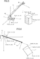
- the crane 10 is fixed to a work position as shown in FIG. 1 .
- the telescopic boom 16 is raised and extended as shown in FIG. 5 , and the stereo camera 30 performs imaging.
- One of imaged images is displayed on the monitor 51.
- the controller 70 controls each of the first and second frame memories 61L, 61R to store an image imaged by the stereo camera 30.
- each of the feature point extractors 62L, 62R extracts a feature point of the image stored in each of the first and second frame memories 61L, 61R.
- an outline (edge) of an image of the building 1 is extracted by image processing, and points Pa to Pd, which are corner portions of the building 1, are extracted by image processing as feature points of the outline. Since extraction of the outline and feature points by image processing is a known technique, explanation thereof is omitted here.
- each of the feature point extractors 62L, 62R extracts the outline of the building 1, and a position of the height imaged by the stereo camera 30 is low, a region for extracting the outline is roughened, and calculation speed can be increased.
- the camera coordinate system position calculator 64 obtains positions of the feature points Pa (x0, y0, z0) to Pd (xd, yd, zd) in a camera coordinate system in which a focal position of the monocular camera 30L is taken as an origin, for example.
- each of the reference point extractors 63L, 63R extracts the three reference points P1, P2, P3 on the carrier 11 of the crane 10 from the image stored in each of the first and second frame memories 61L, 61R. Extraction of each of the three reference points P1, P2, P3 is extracted by a known pattern-matching method, for example.
- the camera coordinate system reference point position calculator 65 obtains positions (x1, y1, z1), (x2, y2, z2), (x3, y3, z3) in the camera coordinate system in which the focal position (not shown) of the monocular camera 30L is taken as the origin, by a later-described principle of position calculation by the stereo camera.
- the correlation calculator 66 obtains a correlation between the positions in the camera coordinate system and the positions in the crane coordinate system.
- the crane coordinate system position calculator 67 obtains a position of the feature point Pa (x0, y0, z0) in the camera coordinate system as a position (X0, Y0, Z0) in the crane coordinate system. Similarly, the crane coordinate system position calculator 67 obtains positions of the feature points Pb to Pd as positions (Xb, Yb, Zb) to (Xd, Yd, Zd) in the crane coordinate system.
- the positions (X0, Y0, Z0) to (Xd, Yd, Zd) in the crane coordinate system of the feature points Pa to Pd obtained by the crane coordinate system position calculator 67 are stored in the memory 68.
- each of the first and second frame memories 61L, 61R stores an image imaged by the stereo camera 30.
- the above operation is repeated.
- Outline and feature points of buildings are extracted, and three-dimensional positions of the feature points are obtained, and therefore, three-dimensional position information of all objects in the surrounding area centering on the crane 10 is obtained.
- the surrounding area of the crane 10 for example, as shown in FIG.
- positions of the feature points Pa to Pd, Qa to Qd are obtained as positions (x0, y0, z0) to (xd, yd, zd), (xqa, yqa, zqa) to (xqd, yqd, zqd) in the camera coordinate system, and then three-dimensional positions (X0, Y0, Z0) to (Xd, Yd, Zd), (Xqa, Yqa, Zqa) to (Xqd, Yqd, Zqd) in the crane coordinate system are obtained (see FIG. 8 ).
- outlines R1, R2 of the buildings 1, 2, and the positions of the feature points Pa to Pd, Qa to Qd of the buildings 1, 2 are stored.
- the map-making processor 80 makes a map in which the buildings 1, 2 are viewed in plan view, based on the outlines R1, R2 of the buildings 1, 2, and the positions (X0, Y0, Z0) to (Xd, Yd, Zd), (Xqa, Yqa, Zqa) to (Xqd, Yqd, Zqd) of the feature points Pa to Pd, Qa to Qd of the buildings 1, 2. That is, the outlines R1, R2 are converted to outlines which are expressed in an X-Y coordinate system in which a Z coordinate value is zero.
- the map-making processor 80 stores only positions (X0, Y0) to (Xd, Yd) in the X-Y coordinate system of the three-dimensional positions of the feature points Pa to Pd of the outline R1 of the building 1 in the image memory 81 so as to correspond to n, m addresses of the image memory 81.
- a line connecting the feature points Pa to Pd is stored in the image memory 81 as an outline F1 of the building 1 as viewed in plan view.
- an inside of the outline F1 is colored according to a Z coordinate value, and stored in the image memory 81.
- positions (Xqa, Yqa) to (Xqd, Yqd) in the X-Y coordinate system of the three-dimensional positions of the feature points Qa to Qd of the outline R2 of the building 2 are stored in the image memory 81 so as to correspond to the n, m addresses of the image memory 81.
- a line connecting the feature points Qa to Qd is stored in the image memory 81 as an outline F2 of the building 2 as viewed in plan view. Additionally, an inside of the outline F2 is colored according to a Z coordinate value, and stored in the image memory 81.
- a map MP shown in FIG. 9 is made and stored.
- color representing the height for example, a case where the height is lower than 10 m is colored in pale blue, a case where the height is equal to or more than 10 m and less than or equal to 20 m is colored in blue, a case where the height is equal to or more than 20 m and less than or equal to 30 m is colored in purple, and a case where the height is equal to or more than 30 m is colored in red.
- the inside of the outline F1 is colored in purple
- the inside of the outline F2 is colored in blue.
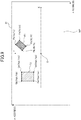
- the map MP stored in the image memory 81 is displayed on the monitor 51 as shown in FIG. 10 .
- a graphic image 10G representing the crane 10 is displayed in an origin position O in the X-Y coordinate system, and a bar-graph image 52 representing a relationship between color and height is displayed, and therefore, an operator recognizes the height of the buildings 1, 2 by the color.
- the graphic image 10G and the bar-graph image 52 can be stored in the image memory 81 beforehand.
- the controller 70 controls the feature point extractors 62L, 62R to extract an outline of the image of the hook block 19.
- the map-making processor 80 composites a graphic image Gf representing the hook 21 and the map MP stored in the memory 68 so as to correspond to the three-dimensional position of the hook 21 stored in the memory 68, and displays the composite image on the monitor 51 as shown in FIG. 10 .
- Color of the graphic image Gf is determined based on a height position of the hook 21, that is, a Z coordinate value. For example, if the height of the hook 21 is equal to or more than 30 m, the graphic image Gf is colored in red.
- the outlines F1, F2 representing the buildings 1, 2, the graphic image Gf of the hook 21, and the graphic image 10G of the crane 10 are displayed so as to correspond to each position, and therefore, it is possible to recognize a positional relationship between the surrounding buildings 1, 2 and the crane 10, and a positional relationship between the hook 21 and the buildings 1, 2 at a glance.
- the map MP is shown in the X-Y coordinate system; however, as shown in FIG. 11 , it can be displayed in polar coordinates V on the monitor 51. If it is thus displayed in the polar coordinates V, in a case of turning the telescopic boom 16, a position to which the hook 21 is moved by this turn is recognized clearly, and it is easier to ensure safety.
- a display in the X-Y coordinate system and a display in a polar coordinate system can be switched.
- the stereo camera 30 is provided at the end portion of the telescopic boom 16; however, the stereo camera 30 does not necessarily need to be provided.
- a monocular camera is provided at the end portion, and from an image imaged by the monocular camera which is obtained by movement of the telescopic boom 16, based on a principle of the stereo camera, three-dimensional position information of the buildings 1, 2 can be obtained.
- a monocular camera and a laser ranging device are provided, and based on measurements of the laser ranging device, the height of an object is obtained, an outline of the object is extracted from an image imaged by the monocular camera, and the outline can be converted to an outline as viewed in plan view based on the height of the object.
- the display of the height is shown by different colors; however, it is not limited thereto, and, for example, it can be shown by shading a same color, or by using a hatch, a dotted line, or the like. Or it can be shown by a numeric value.
- the three reference points P1, P2, P3 are set on the carrier 11 of the crane 10, and the three-dimensional position information of the buildings 1, 2 is obtained; however, if the position of the end portion of the telescopic boom 16 is obtained from the luffing angle, the length, the turning angle, and a deflection amount of the telescopic boom 16, it is possible to obtain three-dimensional positions of the buildings 1, 2 in which a position of the turning center of the telescopic boom 16 is taken as an origin, without setting the three-dimensional points P1, P2, P3.
- the stereo camera 30 faces directly downward (in the vertical direction) and performs imaging, if a Z-axis in the camera coordinate system and a Z-axis in the crane coordinate system are in the same direction, only two reference points may be provided.
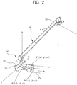
- the X-Y-Z coordinate system of the crane 10 in which the position of the turning center of the telescopic boom 16 on the upper surface of the carrier 11 is taken as the origin is set, and the three-dimensional position information of the buildings 1, 2 is obtained; however, as shown in FIG. 12 , for example, in a coordinate system in which a predetermined position Pc on the upper surface of the carrier 11 of the crane 10 or a predetermined position Pd on the ground is taken as an origin, three-dimensional position information of a building can be obtained.
- h denotes a height from the ground to the upper surface of the carrier 11.
- the predetermined position Pc or the predetermined position Pd
- each building is extracted and a map in which the buildings 1, 2 are viewed in plan view is made; however, only one feature point is extracted, and from the extracted feature point, three-dimensional position information of each building is obtained, and as shown in FIG. 13 , building images 1G, 2G as viewed in plan view, mark images Ma, Mb representing feature points of the buildings, and coordinates expressing three-dimensional positions of the feature points can be displayed on the monitor 51. Additionally, in a center portion of the monitor 51, a crane image 10G is displayed, and the crane image 10G can be a graphic image, for example, an image of the crane 10 imaged by the monocular camera 30L of the stereo camera 30.
- FIG. 14 shows a principle of measurement in which a distance to a photographic object is measured by using a stereo camera.
- 1 denotes a photographic object
- 2 denotes a stereo camera.
- the stereo camera 2 is constituted of two monocular CCD cameras 2A, 2B.
- the CCD cameras 2A, 2B have imaging lenses 3A, 3B, and two-dimensional image sensors 4A, 4B, respectively.
- Reference signs O,1 02 denote optical axes of the imaging lenses 3A, 3B, respectively, and a distance between the optical axes O,1 02 is a baseline length D. Additionally, f denotes a focal length of each of the imaging lenses 3A, 3B, and L denotes a distance from the photographic object 1 to the stereo camera 2.
- the parallax ⁇ is obtained by obtaining a pixel position of each of the photographic object images 1A, 1B with respect to a pixel center on each of the optical axes O1, O2 regarding each of the CCD cameras 2A, 2B.
- an image position (pixel position (x', y')) of the photographic object 1' with respect to an optical axis center (image center) in a two-dimensional coordinates is obtained on a screen.
- a pixel position of the photographic object 1' of the image center is taken as (x' y')
- a distance from the photographic object 1' to an intersection (origin) of a plane which includes the photographic object 1' and is perpendicular to an optical axis of the camera with the optical axis center is taken as (x, y).
- the distance L to the plane which includes the photographic object 1'and is perpendicular to the optical axis of the CCD camera 2A (or 2B), and the distance (x, y) from the origin to the photographic object 1' are obtained. That is, a three-dimensional position of the photographic subject 1' with respect to an origin of 2A (or 2B) is obtained.
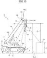
- the above-described stereo camera (three-dimensional position-measuring device) 2 is installed, and the stereo camera 2 is installed at the boom head 16Ca similarly to the stereo camera 30 in the first example.
- FIG. 16 is a block diagram which shows a configuration of a surrounding information-obtaining device 300 in the second example.
- 322 denotes a calculation processor.
- an image signal from the stereo camera 2 a sensor signal from each of a cylinder pressure sensor 323, a boom length sensor 324, a luffing angle sensor 325, and an outrigger projection sensor 326 are inputted.
- the surrounding information-obtaining device 300 shown in FIG. 16 includes the stereo camera 2 which is provided at the end portion 16Ca of the telescopic boom 16, the boom length sensor 324, the luffing angle sensor 325, the outrigger projection sensor 326, the calculation processor (three-dimensional position information-obtaining device) 322, a monitor (display) 327, and the like.
- the calculation processor 322 has an image processor 322A, and a control processor 322B.
- the image processor 322A includes a calculator 322C having a later-described function.
- the control processor 322B performs control processing in accordance with a sensor signal from each of the sensors, and outputs information necessary for control to the monitor 327 as necessary.
- an image signal from the stereo camera 2 is inputted, and the image processor 322A performs image processing on the image signal from the stereo camera 2 accordingly, and outputs a display signal to the monitor 327.
- a display signal to the monitor 327.
- an image W' of the wire W, an image 19' of the hook block 19, an image 11' of a front part of the carrier 11, an image 12' of the outrigger 12, an image Ref' of a later-described reference object Ref, and an image Ob' of a later-described a target object Ob are shown.
- the stereo camera 2 is constituted of the CCD cameras (imaging device) 2A, 2B, two screens are provided in parallel in the monitor 327, and an image imaged by each of the CCD cameras 2A, 2B can be displayed concurrently, or one screen is provided, and a screen selector switch can be provided so as to display an image imaged by one of the CCD cameras 2A, 2B.
- the surrounding information-obtaining device 300 calculates a three-dimensional positon of a camera in a crane coordinate system with respect to a reference position of the crane 10 by output of the sensors 323 to 326, and therefore, by use of a three-dimensional position of the target object Ob in a camera coordinate system obtained by the cameras 2A, 2B, it is possible to calculate a position of the of the object Ob in the crane coordinate system.
- the image processor 322A has a function which determines whether the image Ref of the reference object Ref and the image Ob' of the target object Ob appear together in an image imaged by the stereo camera 2 by image recognition.
- the reference object Ref is formed as a cross mark on a surface in a front part of the carrier 11, here.
- the image processor 322A determines in which pixel position of each of two-dimensional image sensors 4A, 4B the image Ref of the reference object Ref exists by, for example, a widely-known pattern-matching method from an imaged image obtained by each of the CCD cameras 2A, 2B.
- the image processor 322A determines in which pixel position of each of two-dimensional image sensors 4A, 4B the image Ob' of the target object Ob a position of which is desired to be measured exists by, for example, the widely-known pattern matching method from the imaged image obtained by each of the CCD cameras 2A, 2B.
- a position of a target object Ob which is desired to be measured is specified.
- specifying the target object Ob can be performed by an operator pointing to it on the screen G each time.
- the monitor 327 is not the touch-screen type, for example, outlines of the target objects Ob are automatically extracted, and the target objects Ob can be specified.
- the calculator 322C obtains parallax ⁇ from each pixel position of the image Ref' of the reference object Ref by the above-described principle of distance measurement by the stereo camera, and by use of the parallax ⁇ , calculates a distance Z 1 in a height direction from the stereo camera 2 to the reference object Ref.
- the calculator 322C obtains parallax ⁇ from each pixel position of the image Ob' of the target object Ob a height of which is desired to be measured, and by use of the parallax ⁇ , calculates a distance Z 2 in the height direction from the stereo camera 2 to the target object Ob.
- the calculator 322C calculates the distance Z 1 in the height direction from the stereo camera 2 to the reference object Ref, and by use of an image in which the target object Ob is included, calculates the distance Z 2 in the height direction from the stereo camera 2 to the target object Ob, and calculates the height Z from the ground S to the target object Ob by subtracting the distance Z 2 to the target object Ob from a sum of the distance Z 1 in the height direction to the reference object Ref and the reference height Zref.
- the calculator 322C subtracts the distance Z 2 in the height direction to the target object Ob from the distance Z 1 in the height direction to the reference object Ref.
- a target object Ob which has already been obtained is taken as new reference Ref, and a height from the ground to a target object Ob to be obtained next is calculated.
- the cross mark index (reference object Ref) such as the white line, or the like is recognized as a target object ob a height of which is to be measured, and a distance Z 2 ' in the height direction of the target object (cross mark index (reference object Ref")) ob is obtained.
- a building or the like as a target object Ob a height of which is newly desired to be measured and the cross mark index (reference object Ref") are imaged by the stereo camera 2, and the distance Z 2 in the height direction of the building or the like as the target object Ob the height of which is desired to be obtained or the like and a distance Z 1 +Zref in the height direction to the reference object Ref" are obtained.
- the target object Ob the height of which from the ground S is desired to be measured and the reference object Ref do not appear in the image imaged by the stereo camera 2 concurrently, it is possible to accurately obtain the height Z of the target object Ob from ground.
- the image processor 322A performs an imaging step in which the reference object Ref representing the reference height from the ground S and the target object Ob the height of which from the ground S to be measured are imaged by use of the stereo camera 2 which is installed at the telescopic boom 16 of the crane 10, a calculating step in which the distance Z 1 in the height direction from the stereo camera 2 to the reference object Ref, a calculating step in which the distance Z 2 in the height direction from the stereo camera 2 to the target object Ob, and a calculating step in which the height Z from the ground S to the target object Ob is calculated by subtracting the distance Z 2 in the height direction to the target object Ob from the sum of the reference height Zref of the reference object Ref from the ground S and the distance Z 1 in the height direction to the reference object Ref.
- the calculator 322C performs a step in which a height Z of the target object Ob the height of which from the ground S to be newly measured is obtained by using a target object Ob an image Ob' of which is included in the image and a height of which from the ground S which has already been obtained as a new reference object Ref".
- the reference object Ref representing the reference height from the ground S is provided at the crane 10, and therefore, even in a case where the height of the target object Ob from the ground S is measured by the stereo camera 2, it is possible to obtain an effect in which the height of the target object Ob from the ground S is accurately measured.
- the height Z of the target object Ob from the ground S obtained by the calculation and a radius R (distance from a center axis of turning as the turning center of the boom 16 to the object Ob) in a position of the target object Ob are displayed on the screen G, as shown in FIG. 17 .
- the stereo camera 2 which is installed at the telescopic boom 16 of the crane 11 and outputs an image signal by imaging a working site
- the calculator 332C of the image processor 332A which performs an image display of the image signal from the stereo camera 2
- FIG. 19 shows monocular monitoring cameras (CCD cameras) 2A, 2B constituting a stereo camera (three-dimensional position-measuring device) of a surrounding information-obtaining device in a third example.
- Those monitoring cameras 2A, 2B are provided at both ends of the sheave shaft 25 of the boom head 16Ca of the end boom 16C, respectively. That is, the monitoring cameras 2A, 2B are arranged at positions between which the end portion of the end boom 16C is placed in a width direction (in FIG. 19 , a right-left direction: a direction perpendicular to a luffing direction of the telescopic boom 16), respectively, and a distance between the monitoring cameras 2A, 2B becomes larger.
- a distance between optical axes of the monitoring camera 2A, 2B is defined as the baseline length D.
- the monitoring cameras 2A, 2B are installed at the sheave shaft 25 similarly to the first example.
- a surrounding information-obtaining device 400 in the third example shown in FIG. 20 includes a calculation processor (three-dimensional position information-obtaining device) 422, a screen selector switch SW1, and an image composition-processing switch SW2. Since other than the above is similar to those in the second example, explanation thereof is omitted.
- the calculation processor 422 controls a screen display to be switched from an image imaged by the monitoring camera 2B which is arranged on a side close to the cabin 20 shown in FIG. 21B to an image imaged by the monitoring camera 2A which is arranged on a side distant from the cabin 20 (monitoring camera 2A which is arranged on the left as viewed from the operator in the cabin 20), as shown in FIG. 21A .
- the image processor 422A When the operator operates the image composition-processing switch SW2, as shown in FIG. 21C , the image processor 422A performs image processing so as to display a composition-processed image in which the image imaged by the monitoring camera 2B and the image imaged by the monitoring camera 2A are composition-processed.
- the composition-processed image is displayed in which the hook 21 is taken as a center of the screen G, and therefore, it is convenient in a case of performing lifting work.
- the image processor 422A performs image processing such that an image 19' of the hook block 19 is placed in a center O' in a right-left direction of the screen G, and the composition-processed image is displayed on the screen G.
- a display of the screen G is switched to an image imaged by the other of the monitoring cameras 2A, 2B, or a composition-processed image is displayed on the screen G, and therefore, it is possible to work with as few dead spots as possible.
- the removal of the image 19' of the hook block 19 is performed such that, for example, an image of a portion which becomes a dead spot due to the hook block 19 is obtained and stored in a memory when it is out of the dead spot during movement of the hook block 19, and in a case of making a composition-processed image, the image of the portion which becomes the dead spot is composited and concurrently the image 19' of the hook block 19 is removed.
- the image of the portion which becomes the dead spot due to the hook block 19 is displayed preferentially, and the image 19' of the hook block 19 can be a transparent image.
- the surrounding information-obtaining device 400 obtains a three-dimensional position of a target object Ob (see FIG. 18 ) similarly to the surrounding information-obtaining device 300 in the second example, and therefore, explanation thereof is omitted.
- FIG. 22 is a block diagram which shows a configuration of a surrounding information-obtaining device 500 in a fourth example.
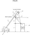
- the surrounding information-obtaining device 500 includes one monocular-monitoring camera (three-dimensional position-measuring device) 501 which is provided at the end portion of the telescopic boom 16 (see FIG. 1 ), a boom posture-detecting sensor 50 which detects a posture of the telescopic boom 16, a tilt angle-detecting sensor S1 and a pan angle-detecting sensor S2 which detect an inclination angle of the monitoring camera 501, an image-processing controller (three-dimensional position information-obtaining device) 560 which processes an image signal outputted from the monitoring camera 501, and obtains a height and the like of a construction I (see FIG. 24 ) as an imaged object, and the monitor 51 which displays an image imaged by the monitoring camera 501.
- monocular-monitoring camera three-dimensional position-measuring device
- the image-processing controller 560 obtains a height of a building based on two images which have been imaged by the monitoring camera 501 in different positions, when the telescopic boom 16 moves from a storage position to a work start position (stand-by position), during movement of work, and the like.
- the image-processing controller 560 includes first and second frame memories 561, 562 each of which is an image-storing device which stores an image imaged by the monitoring camera 501 (see FIG. 24 ), an extractor 563 which extracts a feature point of a construction such as a building or the like from a first image which has been stored in the first frame memory 561, an image convertor 564 which converts a second image which has been stored in the second frame memory 562 to a predetermined image, an extractor 565 which extracts a feature point P of a construction I (see FIG.
- an operation part 566 which performs various calculations in which a distance between optical axes of the first and second images stored in the first and second frame memories 561, 562 is obtained, and from the distance, data detected by the boom posture-detecting sensor 50, and the like, a height of the construction I is obtained, an image compositor 568 which composites a numerical value representing the height of the construction I obtained by the operation part 566 with an image of the construction I, a controller 569 which controls the first and second frame memories 561, 562 to store an image which is being imaged by the monitoring camera 501, and controls the operation part 566 to perform calculation processing, and the like.
- the extractor 563, the image convertor 564, the extractor 565, and the operation part 566 constitute an image calculation-processing device which obtains a three-dimensional position of the construction (object) I, and the image calculation-processing device and the image-storing device constitute a three-dimensional position information-obtaining device.
- the monitoring camera 501 performs imaging in accordance with the extension of the telescopic boom 16, and an imaged image is displayed on the monitor 51.
- the monitoring camera 501 faces directly downward.
- the controller 569 controls the first frame memory 561 to store an image imaged by the monitoring camera 501.
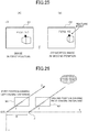
- the extractor 563 extracts an outline (edge) of the imaged image of the construction I by image processing, and additionally as shown in FIG. 25 (A) , extracts a point P1 which is a corner portion of the construction I from the outline as a feature point by image processing, and obtains a position of the feature point P1 as a position (X1, Y1) on an image G1.
- the controller 569 controls the second frame memory 562 to store an image imaged by the monitoring camera 501.
- the image convertor 564 converts the image stored in the second frame memory 562 to be an image which is imaged from a position Q1 where the monitoring camera 501 is in a position at the same height as the first position and moved to the right by L (in FIG. 24 ).
- the extractor 565 extracts an outline (edge) of the image of the same building (construction) as above by image processing based on a converted image G2 shown in FIG. 25 (B) , further extracts a point P2 which is a corner portion from the outline as a feature point by image processing, and obtains a position of the point P2 as a position (X2, Y2) on the image G2.
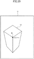
- a position O of a criterion camera is taken as an origin, and each of X, Y, and Z coordinate axes is set.
- a position J of a reference camera is expressed by (B, 0, 0), and a distance between both cameras is denoted by B.
- f denotes a focal length.
- image coordinates (x, y) are set on an image of the projected two-dimensional image. That is, on each of the planes N1, N2, each image coordinate (x, y) is set.
- Each image coordinate (x, y) is two-dimensional coordinates in which each of origins On 1, On 2 is taken as an image center, and each of image coordinate axes x, y is set parallel to each of an X axis and a Y axis in a three-dimensional space.
- a target point T (Xp, Yp, Zp) in the three-dimensional space shown in FIG. 27 is imaged by the two cameras (criterion camera and reference camera).
- the target point T appears in a position U (x L , y L ) in an image of the plane N1 obtained by the criterion camera (left camera), and the target point T appears in a position V (x R , y R ) in an image of the plane N2 obtained by the reference camera (right camera).
- y L y R .
- FIG. 28 is a diagram in which a state shown in FIG. 27 is viewed from above in a Y-axis direction, and a diagram projected in an X-Z plane.
- a triangle ( ⁇ TOJ) made by the target point T (Xp, Yp, Zp) in the three-dimensional space and the positions of the two cameras and a triangle ( ⁇ OEF) made by the position O of the criterion camera and parallax on an image imaged by the criterion camera are similar.
- a straight line C1 and a straight line C2 shown in FIG. 28 are parallel.
- the target point (Xp, Yp, Zp) is obtained as follows.
- the position (X1, Y1) of the feature point P1 (see FIG. 25 ) on the image G1 imaged in the first position shown in FIG. 28 and the position (X2, Y2) of the feature point P2 on the image G2 imaged in the position Q1 are obtained.
- coordinate values of the positions (X1, Y1) and (X2, Y2) values in the three-dimensional space are used.
- the criterion camera is taken as a first position camera
- the reference camera is taken as a second position camera
- a moving distance L in the horizontal direction of the monitoring camera 501 equivalent to the distance B between both cameras
- the height H of the construction I is obtained by obtaining a distance h1 from the expression (3).
- the operation part 566 shown in FIG. 23 obtains the moving distance L of the monitoring camera 501 from a detection signal detected by the boom posture-detecting sensor 50. That is, the operation part 566 obtains the moving distance L based on the luffing angle and the extended length of the telescopic boom 16.
- the operation part 566 obtains the distance h1 in the vertical direction from a position of the monitoring camera 501 (see FIG. 24 ) in the first position to the construction I from the positions U (x L , y L ) and V (x R , y R ) of the images shown in FIG. 27 and the moving distance L based on the above expression (3).
- the operation part 566 obtains a height position h0 of the monitoring camera 501 in the first position shown in FIG. 24 from the detection signal detected by the boom posture-detecting sensor 50, and obtains the height H of the construction I from the distance h1 and the height position h0.
- the height H of the construction I is obtained; however, a feature point of a fixed object such as a material placed on the ground is extracted, and a height of the fixed object can be calculated by a similar method.
- the image compositor 568 composites and displays a black circle mark M representing a position of an extracted feature point P1 (P2) and a numerical value representing the obtained height of the construction I on an image G3 of the construction I displayed on the monitor 51.
- the numerical value representing the height H is displayed in relation to the construction I so as to show that it represents the height of the construction I.
- the numerical value representing the height H is displayed in relation to the construction I so as to show that it represents the height of the construction I.
- the monitoring camera 501 images other construction in addition to the construction I, similarly to the above, a feature point of the other construction is extracted, and a height of the other construction is obtained and displayed on the screen of the monitor 51.
- images thus imaged by the monitoring camera 501 provided at the end portion of the telescopic boom 16 are different in imaging position in accordance with movement of the telescopic boom 16, and image processing is performed on one of the images different in height to the imaging position, and therefore, an image similar to that imaged by a stereo camera is obtained, and the height H of the construction I is obtained. Accordingly, it is possible to obtain the height H of the construction I by one monocular monitoring camera 501.
- the monitoring camera 501 is provided at the end portion of the telescopic boom 16, it is also possible to obtain a height of a high construction I by extending the telescopic boom 16. Furthermore, by performing imaging by the monitoring camera 501 from a high position, it is possible to obtain a height of a construction within a surrounding area necessary for work, and make a stereogram within the surrounding area. Therefore, it is possible to further enhance safety at work.
- the height of the construction I is obtained from the images imaged in the first and second positions; however, during extension of the telescopic boom 16, the height of the construction I is obtained continuously, and the height of the construction I can be determined from a state of distribution of the plurality of heights obtained.
- the height of the monitoring camera 501 is constant, and therefore, it is possible to accurately obtain the height of the construction 1. Accordingly, in a case where after the height of the construction I is obtained, the telescopic boom 16 is turned, the height of the construction I is obtained at the time of this turn, and the height of the construction I can be updated.
- the feature point of the construction is extracted from the imaged image, and the height of the feature point is obtained; however, it is not limited thereto, for example, a touch screen is provided on the screen of the monitor 51, and a desired portion of the image displayed on the screen is touched on the touch screen, and thus the height of the desired portion of the image can be obtained.
- reference points P1 to P3, or the like are set similarly to in the first example, and it is possible to obtain a three-dimensional position of a feature point P of the construction I obtained by, for example, a turning center of the telescopic boom 16 which is taken as an origin, or a predetermined position Pd (see FIG. 12 ) which is taken as an origin.
- the reference point extractors 63L, 63R, the camera coordinate system reference point position calculator 65, the correlation calculator 66, and the crane coordinate system position calculator 67 which are shown in FIG. 4 in the first example, and the like are provided in the image-processing controller 560 shown in FIG. 22 . Additionally, it is possible to obtain the three-dimensional position of the feature point P of the construction I by a similar method to in the third example.
Landscapes
- Engineering & Computer Science (AREA)
- Multimedia (AREA)
- Physics & Mathematics (AREA)
- General Physics & Mathematics (AREA)
- Radar, Positioning & Navigation (AREA)
- Remote Sensing (AREA)
- Mechanical Engineering (AREA)
- Theoretical Computer Science (AREA)
- Automation & Control Theory (AREA)
- General Engineering & Computer Science (AREA)
- Civil Engineering (AREA)
- Structural Engineering (AREA)
- Computer Vision & Pattern Recognition (AREA)
- Mining & Mineral Resources (AREA)
- Health & Medical Sciences (AREA)
- Biomedical Technology (AREA)
- General Health & Medical Sciences (AREA)
- Signal Processing (AREA)
- Length Measuring Devices By Optical Means (AREA)
- Measurement Of Optical Distance (AREA)
- Jib Cranes (AREA)
Applications Claiming Priority (8)
| Application Number | Priority Date | Filing Date | Title |
|---|---|---|---|
| JP2012207769A JP6080450B2 (ja) | 2012-09-21 | 2012-09-21 | 監視カメラ装置 |
| JP2012260730A JP6146994B2 (ja) | 2012-11-29 | 2012-11-29 | クレーンの監視カメラ |
| JP2012260731A JP6097063B2 (ja) | 2012-11-29 | 2012-11-29 | 高さ測定装置及び高さ測定方法 |
| JP2013020351 | 2013-02-05 | ||
| JP2013020350A JP6222933B2 (ja) | 2013-02-05 | 2013-02-05 | 作業車用の地図作成装置 |
| JP2013160884A JP6257947B2 (ja) | 2013-02-05 | 2013-08-02 | 作業車の周囲情報取得装置 |
| PCT/JP2013/075373 WO2014046213A1 (ja) | 2012-09-21 | 2013-09-19 | 作業車の周囲情報取得装置 |
| EP13838454.0A EP2899496B1 (de) | 2012-09-21 | 2013-09-19 | Vorrichtung zur peripherieinformationserfassung für ein fahrzeug |
Related Parent Applications (2)
| Application Number | Title | Priority Date | Filing Date |
|---|---|---|---|
| EP13838454.0A Division EP2899496B1 (de) | 2012-09-21 | 2013-09-19 | Vorrichtung zur peripherieinformationserfassung für ein fahrzeug |
| EP13838454.0A Division-Into EP2899496B1 (de) | 2012-09-21 | 2013-09-19 | Vorrichtung zur peripherieinformationserfassung für ein fahrzeug |
Publications (4)
| Publication Number | Publication Date |
|---|---|
| EP3235773A2 true EP3235773A2 (de) | 2017-10-25 |
| EP3235773A3 EP3235773A3 (de) | 2017-12-06 |
| EP3235773B1 EP3235773B1 (de) | 2023-08-16 |
| EP3235773B8 EP3235773B8 (de) | 2023-09-20 |
Family
ID=53252061
Family Applications (2)
| Application Number | Title | Priority Date | Filing Date |
|---|---|---|---|
| EP17168541.5A Active EP3235773B8 (de) | 2012-09-21 | 2013-09-19 | Vorrichtung zum erhalt von umgebungsinformationen für ein arbeitsfahrzeug |
| EP13838454.0A Active EP2899496B1 (de) | 2012-09-21 | 2013-09-19 | Vorrichtung zur peripherieinformationserfassung für ein fahrzeug |
Family Applications After (1)
| Application Number | Title | Priority Date | Filing Date |
|---|---|---|---|
| EP13838454.0A Active EP2899496B1 (de) | 2012-09-21 | 2013-09-19 | Vorrichtung zur peripherieinformationserfassung für ein fahrzeug |
Country Status (4)
| Country | Link |
|---|---|
| US (1) | US9300954B2 (de) |
| EP (2) | EP3235773B8 (de) |
| CN (1) | CN104662389B (de) |
| WO (1) | WO2014046213A1 (de) |
Cited By (3)
| Publication number | Priority date | Publication date | Assignee | Title |
|---|---|---|---|---|
| EP3153348B1 (de) | 2015-10-05 | 2020-07-01 | Franz Xaver Meiller Fahrzeug- und Maschinenfabrik - GmbH & Co KG | Lastentransportfahrzeug mit überwachungsmitteln zur gesicherten handhabung eines wechselbehälters |
| WO2020254332A1 (de) | 2019-06-21 | 2020-12-24 | Tadano Demag Gmbh | Verfahren zum betrieb eines fahrzeugkrans |
| RU2743213C2 (ru) * | 2018-07-13 | 2021-02-16 | Эпзилон Кран Гмбх. | Кран, имеющий систему регистрации изображений |
Families Citing this family (97)
| Publication number | Priority date | Publication date | Assignee | Title |
|---|---|---|---|---|
| DE102013006258A1 (de) | 2013-04-11 | 2014-10-16 | Liebherr-Components Biberach Gmbh | Kran |
| US10937187B2 (en) | 2013-10-07 | 2021-03-02 | Apple Inc. | Method and system for providing position or movement information for controlling at least one function of an environment |
| AU2013402725B2 (en) * | 2013-10-07 | 2018-04-12 | Apple Inc. | Method and system for providing position or movement information for controlling at least one function of a vehicle |
| WO2015076770A1 (en) * | 2013-11-25 | 2015-05-28 | Kadir Koymen Film Yapimi Sinema Ekipmanlari Uretimi Ithalat Ve Ihracat A.S. | Targeting for a crane |
| JP6403393B2 (ja) * | 2014-02-12 | 2018-10-10 | 住友重機械工業株式会社 | 画像生成装置 |
| EP2980599A1 (de) * | 2014-08-01 | 2016-02-03 | Hilti Aktiengesellschaft | Trackingverfahren und Trackingsystem |
| JP6389087B2 (ja) * | 2014-09-11 | 2018-09-12 | 古河ユニック株式会社 | 作業機用ブーム衝突回避装置 |
| EP3000763B1 (de) | 2014-09-25 | 2022-07-27 | Konecranes Global Corporation | Selbstausfahrendes teleskopisches auslegerkransystem |
| JP5959073B2 (ja) * | 2014-09-30 | 2016-08-02 | インターナショナル・ビジネス・マシーンズ・コーポレーションInternational Business Machines Corporation | 検出装置、検出方法、及び、プログラム |
| US9783377B2 (en) * | 2014-12-03 | 2017-10-10 | Android Industries Llc | Material unloader system |
| US9850109B2 (en) * | 2014-12-23 | 2017-12-26 | Manitowoc Crane Companies, Llc | Crane 3D workspace spatial techniques for crane operation in proximity of obstacles |
| US10822208B2 (en) | 2014-12-23 | 2020-11-03 | Manitowoc Crane Companies, Llc | Crane 3D workspace spatial techniques for crane operation in proximity of obstacles |
| EP3048557B1 (de) * | 2015-01-20 | 2019-09-25 | Aptiv Technologies Limited | Verfahren zum Ermitteln einer Lage eines Fahrzeugmerkmals |
| DE102015202734A1 (de) * | 2015-02-16 | 2016-08-18 | Terex Cranes Germany Gmbh | Kran und Verfahren zum Beeinflussen einer Verformung eines Auslegersystems eines derartigen Krans |
| JP6302860B2 (ja) * | 2015-03-03 | 2018-03-28 | ヤンマー株式会社 | 船舶 |
| FI127606B (fi) * | 2015-04-01 | 2018-10-15 | Konecranes Oyj | Menetelmä, kuormankäsittelylaite, tietokoneohjelma ja tietokoneohjelmatuote tartuntavälineiden paikantamiseksi |
| CN107567412B (zh) | 2015-04-10 | 2020-11-24 | 罗伯特·博世有限公司 | 利用汽车相机使用车辆运动数据的对象位置测量 |
| WO2017033991A1 (ja) | 2015-08-26 | 2017-03-02 | 住友建機株式会社 | ショベルの計測装置 |
| CN107407075B (zh) * | 2015-09-30 | 2020-09-25 | 株式会社小松制作所 | 图像数据生成方法 |
| DE112016003683T5 (de) | 2015-10-05 | 2018-05-03 | Komatsu Ltd. | Baumaschine und bauverwaltungssystem |
| CN105507590B (zh) * | 2015-11-30 | 2017-10-13 | 北汽福田汽车股份有限公司 | 一种卸料控制方法、装置以及工程机械 |
| CN108603359A (zh) * | 2016-01-28 | 2018-09-28 | 住友建机株式会社 | 挖土机 |
| US10544012B2 (en) | 2016-01-29 | 2020-01-28 | Manitowoc Crane Companies, Llc | Visual outrigger monitoring system |
| EP4206113A1 (de) * | 2016-03-23 | 2023-07-05 | Hiab AB | Lasthandhabungsanordnung |
| CN105776042B (zh) * | 2016-05-17 | 2017-10-27 | 中船第九设计研究院工程有限公司 | 一种船坞平台上的起重机防撞监测方法 |
| JP6701018B2 (ja) * | 2016-07-19 | 2020-05-27 | キヤノン株式会社 | 情報処理装置、情報処理方法及びプログラム |
| JP6527848B2 (ja) * | 2016-10-18 | 2019-06-05 | 東芝ロジスティクス株式会社 | 監視装置及びプログラム |
| DE112017004688B4 (de) | 2016-10-31 | 2022-10-27 | Komatsu Ltd. | Messsystem, Arbeitsmaschine und Messverfahren |
| US11130658B2 (en) | 2016-11-22 | 2021-09-28 | Manitowoc Crane Companies, Llc | Optical detection and analysis of a counterweight assembly on a crane |
| WO2018105117A1 (ja) * | 2016-12-09 | 2018-06-14 | 三菱電機ビルテクノサービス株式会社 | 工事写真管理システム |
| JP6760030B2 (ja) * | 2016-12-09 | 2020-09-23 | 株式会社タダノ | クレーン |
| DE102016015388B4 (de) * | 2016-12-22 | 2024-09-12 | Liebherr-Werk Ehingen Gmbh | Verfahren zur assistierten Ausführung von Kranbewegungen eines Krans sowie Kran |
| EP3560881B1 (de) * | 2016-12-27 | 2023-06-14 | Xuzhou Heavy Machinery Co., Ltd. | Verfahren und system zur steuerung des betriebs eines krans, und kran |
| JP6794879B2 (ja) * | 2017-03-10 | 2020-12-02 | 株式会社タダノ | 作業車両用の人物検知システムおよびこれを備える作業車両 |
| SE1750308A1 (sv) | 2017-03-15 | 2018-09-16 | Cargotec Patenter Ab | A vehicle with a crane with object detecting device |
| SE541180C2 (en) * | 2017-04-03 | 2019-04-23 | Cargotec Patenter Ab | Driver assistance system for a vehicle provided with a crane using 3D representations |
| SE540869C2 (en) | 2017-04-11 | 2018-12-11 | Cargotec Patenter Ab | A three dimensional presentation system using an orientation sensor and a digital curtain |
| DE102017207555A1 (de) * | 2017-05-05 | 2018-11-08 | Robert Bosch Gmbh | Einrichtung, Vorrichtung und Verfahren zum Betrieb von autonomen, mit Kleinladungsträgern beladbaren Transportfahrzeugen |
| CN106952479A (zh) * | 2017-05-18 | 2017-07-14 | 南京云趟信息技术有限公司 | 一种用于渣土车卸货监测的视频识别方法 |
| CN107071368A (zh) * | 2017-05-18 | 2017-08-18 | 南京云计趟信息技术有限公司 | 一种用于渣土车举升卸货的视频监测方法 |
| JP6928499B2 (ja) * | 2017-07-21 | 2021-09-01 | 株式会社タダノ | ガイド情報表示装置および作業機 |
| JP6845106B2 (ja) * | 2017-07-21 | 2021-03-17 | 株式会社タダノ | 点群データのクラスタリング方法、ガイド情報表示装置およびクレーン |
| JP6907061B2 (ja) * | 2017-07-21 | 2021-07-21 | 株式会社タダノ | 測定対象物の上面推定方法、ガイド情報表示装置およびクレーン |
| JP6965050B2 (ja) * | 2017-07-21 | 2021-11-10 | 株式会社タダノ | ガイド情報表示装置およびこれを備えたクレーンおよびガイド情報表示方法 |
| DE202017104706U1 (de) | 2017-08-07 | 2017-09-27 | Liebherr-Werk Ehingen Gmbh | Raupenkran |
| DE102017120613B4 (de) * | 2017-09-07 | 2024-03-14 | Liebherr-Werk Ehingen Gmbh | Verfahren zum Bewegen einer Last mit einem Kran |
| JP6840645B2 (ja) | 2017-09-08 | 2021-03-10 | 株式会社小松製作所 | 施工管理装置および施工管理方法 |
| JP6828650B2 (ja) * | 2017-10-04 | 2021-02-10 | 株式会社タダノ | クレーンの制御方法及びクレーン |
| CN107882080B (zh) * | 2017-11-08 | 2019-12-31 | 苏州蓝博控制技术有限公司 | 挖掘机精细工作控制方法、系统及挖掘机 |
| PL3495202T3 (pl) | 2017-12-05 | 2021-02-08 | Guima Palfinger S.A.S. | System detekcji montowany na ciężarówce |
| KR102306145B1 (ko) * | 2017-12-14 | 2021-09-27 | 가부시키가이샤 마에다세이사쿠쇼 | 이동식 크레인의 붐 선회각도 검출장치 |
| US10657666B2 (en) * | 2017-12-22 | 2020-05-19 | Symbol Technologies, Llc | Systems and methods for determining commercial trailer fullness |
| JP6900897B2 (ja) * | 2017-12-25 | 2021-07-07 | コベルコ建機株式会社 | 建設機械の障害物検出装置 |
| TWI688502B (zh) * | 2018-02-14 | 2020-03-21 | 先進光電科技股份有限公司 | 用於警告車輛障礙物的設備 |
| JP7232437B2 (ja) * | 2018-02-19 | 2023-03-03 | 国立大学法人 東京大学 | 作業車両の表示システム及び生成方法 |
| JP7091729B2 (ja) * | 2018-03-09 | 2022-06-28 | 株式会社タダノ | 遠隔操作端末および遠隔操作端末を備える作業車両 |
| JP6857147B2 (ja) * | 2018-03-15 | 2021-04-14 | 株式会社日立製作所 | 三次元画像処理装置、及び三次元画像処理方法 |
| US10519008B1 (en) * | 2018-06-19 | 2019-12-31 | Jim Riley | Crane load centering assembly |
| JP7099150B2 (ja) * | 2018-08-02 | 2022-07-12 | 株式会社タダノ | クレーン及び情報共有システム |
| US10829911B2 (en) * | 2018-09-05 | 2020-11-10 | Deere & Company | Visual assistance and control system for a work machine |
| CN109059780B (zh) | 2018-09-11 | 2019-10-15 | 百度在线网络技术(北京)有限公司 | 检测障碍物高度的方法、装置、设备及存储介质 |
| CN112912332B (zh) * | 2018-10-16 | 2023-08-01 | 株式会社多田野 | 起重机装置 |
| JP7172442B2 (ja) * | 2018-10-25 | 2022-11-16 | 株式会社タダノ | 変形量計測装置及び変形量計測方法 |
| JP7172443B2 (ja) * | 2018-10-25 | 2022-11-16 | 株式会社タダノ | クレーン車 |
| IT201800010013A1 (it) * | 2018-11-02 | 2020-05-02 | Inail Istituto Naz Per L’Assicurazione Contro Gli Infortuni Sul Lavoro | Dispositivo di sicurezza per la conduzione di operazioni di movimentazione di carichi |
| US12358763B2 (en) | 2018-11-07 | 2025-07-15 | Manitowoc Crane Companies, Llc | System for determining crane status using optical and/or electromagnetic sensors |
| CN109396086B (zh) * | 2018-11-27 | 2023-10-31 | 长安大学 | 一种全自动多自由度路灯清洗装置及其控制方法 |
| JP7192527B2 (ja) | 2019-01-23 | 2022-12-20 | 株式会社タダノ | クレーン |
| CN109816778B (zh) * | 2019-01-25 | 2023-04-07 | 北京百度网讯科技有限公司 | 物料堆三维重建方法、装置、电子设备和计算机可读介质 |
| DE102019113881A1 (de) * | 2019-02-12 | 2020-08-13 | Putzmeister Engineering Gmbh | Betonpumpe und Verfahren zum Abstützen einer Betonpumpe |
| US11618655B2 (en) | 2019-03-28 | 2023-04-04 | International Business Machines Corporation | Camera-assisted crane safety |
| WO2020235450A1 (ja) | 2019-05-17 | 2020-11-26 | コベルコ建機株式会社 | 作業機械および作業機械における映像表示制御方法 |
| JP7416063B2 (ja) * | 2019-05-22 | 2024-01-17 | 株式会社タダノ | 遠隔操作端末および遠隔操作端末を備える移動式クレーン |
| US11905146B2 (en) * | 2019-06-20 | 2024-02-20 | Tadano Ltd. | Movable range display system and crane equipped with movable range display system |
| DE102019118902A1 (de) * | 2019-07-12 | 2021-01-14 | Putzmeister Engineering Gmbh | Fahrbare Betonpumpe |
| CN110516018B (zh) * | 2019-08-05 | 2022-03-15 | 山东开创云计算有限公司 | 一种河道的电子绘制方法和装置 |
| US11970839B2 (en) | 2019-09-05 | 2024-04-30 | Deere & Company | Excavator with improved movement sensing |
| US11821167B2 (en) | 2019-09-05 | 2023-11-21 | Deere & Company | Excavator with improved movement sensing |
| US20220332550A1 (en) * | 2019-09-25 | 2022-10-20 | Tadano Ltd. | Control system and work machine |
| CN111017726B (zh) * | 2019-11-19 | 2020-08-21 | 中联重科股份有限公司 | 起重机吊钩定位方法、装置、系统及工程机械 |
| US11693411B2 (en) | 2020-02-27 | 2023-07-04 | Deere & Company | Machine dump body control using object detection |
| JP7369653B2 (ja) * | 2020-03-26 | 2023-10-26 | 株式会社タダノ | ガイド表示システムおよびこれを備えたクレーン |
| AT524402B1 (de) * | 2020-11-11 | 2025-07-15 | Plasser & Theurer Export Von Bahnbaumaschinen Gmbh | Verfahren und mobiles Messsystem zum Vermessen eines Infrastrukturbauteils, insbesondere eines Gleisstrukturbauteils |
| IL303727B1 (en) * | 2021-02-17 | 2026-02-01 | Murata Machinery Ltd | Aerial transport vehicle |
| CN113115216B (zh) * | 2021-02-22 | 2022-09-06 | 浙江大华技术股份有限公司 | 室内定位方法、业务管理服务器及计算机存储介质 |
| US12195306B2 (en) | 2021-04-12 | 2025-01-14 | Structural Services, Inc. | Systems and methods for identifying and locating building material objects |
| AU2022258326A1 (en) | 2021-04-12 | 2023-11-23 | Structural Services, Inc. | Systems and methods for assisting a crane operator |
| CN114408751B (zh) * | 2021-12-27 | 2023-05-30 | 上海旷通科技有限公司 | 一种吊钩辅助定位的方法及设备 |
| JP2023127864A (ja) * | 2022-03-02 | 2023-09-14 | コベルコ建機株式会社 | 遠隔操作処理装置、及び遠隔操作処理システム |
| CN115143930B (zh) * | 2022-06-27 | 2024-05-24 | 徐州徐工挖掘机械有限公司 | 一种单目摄像头测距方法、系统及挖掘机 |
| CN115539063B (zh) * | 2022-09-19 | 2026-04-14 | 上海中联重科桩工机械有限公司 | 具有防撞功能的悬臂运输机及悬臂掘进机、控制方法 |
| US12234627B2 (en) | 2022-12-22 | 2025-02-25 | Caterpillar Sarl | Object visualization in construction heavy equipment |
| WO2024172819A1 (en) * | 2023-02-17 | 2024-08-22 | Structural Services, Inc. | Systems and methods for identifying and locating building material objects |
| US20240308830A1 (en) * | 2023-03-13 | 2024-09-19 | Oshkosh Corporation | Systems and methods for direction of travel |
| IT202300018924A1 (it) * | 2023-09-14 | 2025-03-14 | Merlo Project Srl | Veicolo sollevatore multifunzionale e relativo dispositivo visore a realtà mista |
| CN117208738B (zh) * | 2023-11-09 | 2024-02-23 | 江苏海川电气制造股份有限公司 | 一种变压器制造用转运吊具 |
| CN119461113B (zh) * | 2025-01-14 | 2025-06-17 | 河南工学院 | 用于起重机的智能监控预警方法、系统及存储介质 |
Citations (1)
| Publication number | Priority date | Publication date | Assignee | Title |
|---|---|---|---|---|
| JP2010248777A (ja) | 2009-04-15 | 2010-11-04 | Caterpillar Sarl | 作業機械の管理システム |
Family Cites Families (21)
| Publication number | Priority date | Publication date | Assignee | Title |
|---|---|---|---|---|
| JPH0651558B2 (ja) * | 1990-01-12 | 1994-07-06 | 株式会社東芝 | 活線作業用マニピュレータシステム |
| JPH04184203A (ja) | 1990-11-20 | 1992-07-01 | Komatsu Ltd | 位置計測装置の制御装置 |
| JP2000034093A (ja) * | 1998-07-21 | 2000-02-02 | Kobe Steel Ltd | 旋回式作業機械とその安全作業領域及び定格荷重の設定方法 |
| JP3330879B2 (ja) | 1998-10-02 | 2002-09-30 | 国土交通省関東地方整備局長 | 色検知機能を利用した対物認証システム |
| JP3661462B2 (ja) * | 1998-12-16 | 2005-06-15 | 株式会社日立製作所 | 建屋外揚重機による建屋内における機器のハンドリング方法 |
| JP2002176641A (ja) | 2000-12-05 | 2002-06-21 | Matsushita Electric Ind Co Ltd | 周囲映像提示装置 |
| JP3988574B2 (ja) | 2002-08-08 | 2007-10-10 | 日産自動車株式会社 | 画像処理装置 |
| JP3859574B2 (ja) * | 2002-10-23 | 2006-12-20 | ファナック株式会社 | 3次元視覚センサ |
| JP2007015814A (ja) | 2005-07-07 | 2007-01-25 | Mitsubishi Electric Corp | 機器搬入出システム |
| DE102006027202A1 (de) * | 2006-06-12 | 2007-12-13 | Liebherr-Werk Nenzing Gmbh, Nenzing | Kraneinsatzplaner |
| JP4830696B2 (ja) * | 2006-07-31 | 2011-12-07 | オムロン株式会社 | 物体認識装置、監視システム、物体認識方法、物体認識プログラム、および該プログラムを記録した記録媒体 |
| JP2009155056A (ja) * | 2007-12-27 | 2009-07-16 | Seiko Precision Inc | 画像処理装置、荷物搬送設備、及びプログラム |
| JP4788722B2 (ja) | 2008-02-26 | 2011-10-05 | トヨタ自動車株式会社 | 自律移動ロボット、自己位置推定方法、環境地図の生成方法、環境地図の生成装置、及び環境地図のデータ構造 |
| JP2010241548A (ja) * | 2009-04-03 | 2010-10-28 | Kansai Electric Power Co Inc:The | クレーンの安全確認装置 |
| CN201473235U (zh) * | 2009-07-24 | 2010-05-19 | 金陵科技学院 | 塔吊式起重机用立体视觉安全报警系统 |
| EP2327652B1 (de) * | 2009-11-30 | 2012-09-19 | Siemens Aktiengesellschaft | Verfahren zur Ermittlung von Position und Orientierung eines dreidimensionalen Objekts, Steuerungsprogramm und Postionierungserfassungssystem |
| JP5642409B2 (ja) * | 2010-03-30 | 2014-12-17 | 株式会社タダノ | クレーンの制御装置及びクレーン |
| WO2012037157A2 (en) * | 2010-09-13 | 2012-03-22 | Alt Software (Us) Llc | System and method for displaying data having spatial coordinates |
| US9238570B2 (en) * | 2011-07-05 | 2016-01-19 | Trimble Navigation Limited | Crane maneuvering assistance |
| FI20115922A0 (fi) * | 2011-09-20 | 2011-09-20 | Konecranes Oyj | Nosturin ohjaus |
| US9415976B2 (en) * | 2012-05-10 | 2016-08-16 | Trimble Navigation Limited | Crane collision avoidance |
-
2013
- 2013-09-19 US US14/429,753 patent/US9300954B2/en active Active
- 2013-09-19 EP EP17168541.5A patent/EP3235773B8/de active Active
- 2013-09-19 EP EP13838454.0A patent/EP2899496B1/de active Active
- 2013-09-19 WO PCT/JP2013/075373 patent/WO2014046213A1/ja not_active Ceased
- 2013-09-19 CN CN201380049221.1A patent/CN104662389B/zh active Active
Patent Citations (1)
| Publication number | Priority date | Publication date | Assignee | Title |
|---|---|---|---|---|
| JP2010248777A (ja) | 2009-04-15 | 2010-11-04 | Caterpillar Sarl | 作業機械の管理システム |
Cited By (7)
| Publication number | Priority date | Publication date | Assignee | Title |
|---|---|---|---|---|
| EP3153348B1 (de) | 2015-10-05 | 2020-07-01 | Franz Xaver Meiller Fahrzeug- und Maschinenfabrik - GmbH & Co KG | Lastentransportfahrzeug mit überwachungsmitteln zur gesicherten handhabung eines wechselbehälters |
| EP3153348B2 (de) † | 2015-10-05 | 2023-12-27 | Franz Xaver Meiller Fahrzeug- und Maschinenfabrik - GmbH & Co KG | Lastentransportfahrzeug mit überwachungsmitteln zur gesicherten handhabung eines wechselbehälters |
| RU2743213C2 (ru) * | 2018-07-13 | 2021-02-16 | Эпзилон Кран Гмбх. | Кран, имеющий систему регистрации изображений |
| US10968083B2 (en) | 2018-07-13 | 2021-04-06 | Epsilon Kran Gmbh | Crane comprising an image acquisition system |
| WO2020254332A1 (de) | 2019-06-21 | 2020-12-24 | Tadano Demag Gmbh | Verfahren zum betrieb eines fahrzeugkrans |
| DE102019116759A1 (de) * | 2019-06-21 | 2020-12-24 | Tadano Demag Gmbh | Verfahren zum Betrieb eines Fahrzeugkrans |
| US11866305B2 (en) | 2019-06-21 | 2024-01-09 | Tadano Demag Gmbh | Method for operating a vehicle crane |
Also Published As
| Publication number | Publication date |
|---|---|
| WO2014046213A1 (ja) | 2014-03-27 |
| CN104662389B (zh) | 2017-06-16 |
| US20150249821A1 (en) | 2015-09-03 |
| EP2899496A1 (de) | 2015-07-29 |
| EP3235773B1 (de) | 2023-08-16 |
| EP3235773A3 (de) | 2017-12-06 |
| EP2899496A4 (de) | 2016-08-31 |
| EP2899496B1 (de) | 2020-03-04 |
| US9300954B2 (en) | 2016-03-29 |
| EP3235773B8 (de) | 2023-09-20 |
| CN104662389A (zh) | 2015-05-27 |
Similar Documents
| Publication | Publication Date | Title |
|---|---|---|
| EP2899496B1 (de) | Vorrichtung zur peripherieinformationserfassung für ein fahrzeug | |
| CN111874821B (zh) | 点群数据的聚类方法、向导信息显示装置及起重机 | |
| EP3606861B1 (de) | Fahrerassistenzsysteme und verfahren | |
| CN111943043B (zh) | 引导信息显示装置和具备该装置的起重机、引导信息显示方法 | |
| CN111943050B (zh) | 引导信息显示装置、具有该引导信息显示装置的起重机和引导信息显示方法 | |
| KR101123738B1 (ko) | 중장비 동작 안전 모니터링 시스템 및 방법 | |
| JP6222933B2 (ja) | 作業車用の地図作成装置 | |
| JP5337658B2 (ja) | 広角撮像装置及び測定システム | |
| JP6895835B2 (ja) | ガイド情報表示装置およびクレーン | |
| JP6760030B2 (ja) | クレーン | |
| EP3589575B1 (de) | Fahrzeug mit einer anordnung zur bestimmung einer dreidimensionalen darstellung eines beweglichen elements | |
| JP2014062795A (ja) | 作業機械用周辺監視装置 | |
| JP6080450B2 (ja) | 監視カメラ装置 | |
| JP6257947B2 (ja) | 作業車の周囲情報取得装置 | |
| JP2016119559A (ja) | 作業機械の周囲監視装置 | |
| JP2019023567A (ja) | 地表面推定方法、ガイド情報表示装置およびクレーン | |
| JP6097063B2 (ja) | 高さ測定装置及び高さ測定方法 | |
| WO2019017472A1 (ja) | ガイド情報表示装置、クレーンおよびガイド情報の生成方法 | |
| JP2013009267A (ja) | 周囲監視装置 | |
| JP2021183536A (ja) | コンテナクレーンの運転支援装置 |
Legal Events
| Date | Code | Title | Description |
|---|---|---|---|
| PUAI | Public reference made under article 153(3) epc to a published international application that has entered the european phase |
Free format text: ORIGINAL CODE: 0009012 |
|
| STAA | Information on the status of an ep patent application or granted ep patent |
Free format text: STATUS: REQUEST FOR EXAMINATION WAS MADE |
|
| 17P | Request for examination filed |
Effective date: 20170427 |
|
| AC | Divisional application: reference to earlier application |
Ref document number: 2899496 Country of ref document: EP Kind code of ref document: P |
|
| AK | Designated contracting states |
Kind code of ref document: A2 Designated state(s): AL AT BE BG CH CY CZ DE DK EE ES FI FR GB GR HR HU IE IS IT LI LT LU LV MC MK MT NL NO PL PT RO RS SE SI SK SM TR |
|
| PUAL | Search report despatched |
Free format text: ORIGINAL CODE: 0009013 |
|
| AK | Designated contracting states |
Kind code of ref document: A3 Designated state(s): AL AT BE BG CH CY CZ DE DK EE ES FI FR GB GR HR HU IE IS IT LI LT LU LV MC MK MT NL NO PL PT RO RS SE SI SK SM TR |
|
| RIC1 | Information provided on ipc code assigned before grant |
Ipc: G06T 7/00 20170101ALI20171102BHEP Ipc: G06K 9/00 20060101ALI20171102BHEP Ipc: G05D 1/02 20060101ALI20171102BHEP Ipc: B66C 23/88 20060101ALI20171102BHEP Ipc: H04N 17/00 20060101ALI20171102BHEP Ipc: G06T 7/73 20170101ALI20171102BHEP Ipc: B66C 13/00 20060101ALI20171102BHEP Ipc: G06T 7/593 20170101ALI20171102BHEP Ipc: E02F 9/24 20060101ALI20171102BHEP Ipc: G01B 11/02 20060101ALI20171102BHEP Ipc: B66C 13/46 20060101AFI20171102BHEP Ipc: B60R 1/00 20060101ALI20171102BHEP Ipc: E02F 9/26 20060101ALI20171102BHEP Ipc: G01B 11/245 20060101ALI20171102BHEP Ipc: G01B 11/25 20060101ALI20171102BHEP Ipc: G01C 11/06 20060101ALI20171102BHEP |
|
| STAA | Information on the status of an ep patent application or granted ep patent |
Free format text: STATUS: EXAMINATION IS IN PROGRESS |
|
| 17Q | First examination report despatched |
Effective date: 20190207 |
|
| REG | Reference to a national code |
Ref country code: DE Ref legal event code: R079 Free format text: PREVIOUS MAIN CLASS: B66C0013460000 Ipc: G06V0020000000 Ref country code: DE Ref legal event code: R079 Ref document number: 602013084463 Country of ref document: DE Free format text: PREVIOUS MAIN CLASS: B66C0013460000 Ipc: G06V0020000000 |
|
| GRAP | Despatch of communication of intention to grant a patent |
Free format text: ORIGINAL CODE: EPIDOSNIGR1 |
|
| STAA | Information on the status of an ep patent application or granted ep patent |
Free format text: STATUS: GRANT OF PATENT IS INTENDED |
|
| RIC1 | Information provided on ipc code assigned before grant |
Ipc: G06T 7/593 20170101ALI20230303BHEP Ipc: G06T 7/73 20170101ALI20230303BHEP Ipc: G01B 11/245 20060101ALI20230303BHEP Ipc: G01B 11/02 20060101ALI20230303BHEP Ipc: E02F 9/26 20060101ALI20230303BHEP Ipc: E02F 9/24 20060101ALI20230303BHEP Ipc: G01C 11/06 20060101ALI20230303BHEP Ipc: B66C 23/88 20060101ALI20230303BHEP Ipc: B66C 13/46 20060101ALI20230303BHEP Ipc: G06V 20/00 20220101AFI20230303BHEP |
|
| INTG | Intention to grant announced |
Effective date: 20230405 |
|
| GRAS | Grant fee paid |
Free format text: ORIGINAL CODE: EPIDOSNIGR3 |
|
| GRAA | (expected) grant |
Free format text: ORIGINAL CODE: 0009210 |
|
| STAA | Information on the status of an ep patent application or granted ep patent |
Free format text: STATUS: THE PATENT HAS BEEN GRANTED |
|
| GRAT | Correction requested after decision to grant or after decision to maintain patent in amended form |
Free format text: ORIGINAL CODE: EPIDOSNCDEC |
|
| REG | Reference to a national code |
Ref country code: DE Ref legal event code: R081 Ref document number: 602013084463 Country of ref document: DE Owner name: TADANO LTD., TAKAMATSU-SHI, JP Free format text: FORMER OWNER: TADANO, LTD., TAKAMATSU, KAGAWA, JP |
|
| AC | Divisional application: reference to earlier application |
Ref document number: 2899496 Country of ref document: EP Kind code of ref document: P |
|
| AK | Designated contracting states |
Kind code of ref document: B1 Designated state(s): AL AT BE BG CH CY CZ DE DK EE ES FI FR GB GR HR HU IE IS IT LI LT LU LV MC MK MT NL NO PL PT RO RS SE SI SK SM TR |
|
| REG | Reference to a national code |
Ref country code: GB Ref legal event code: FG4D |
|
| REG | Reference to a national code |
Ref country code: CH Ref legal event code: PK Free format text: BERICHTIGUNG B8 Ref country code: CH Ref legal event code: EP Ref country code: DE Ref legal event code: R096 Ref document number: 602013084463 Country of ref document: DE |
|
| RAP4 | Party data changed (patent owner data changed or rights of a patent transferred) |
Owner name: TADANO LTD. |
|
| REG | Reference to a national code |
Ref country code: IE Ref legal event code: FG4D |
|
| REG | Reference to a national code |
Ref country code: LT Ref legal event code: MG9D |
|
| REG | Reference to a national code |
Ref country code: NL Ref legal event code: MP Effective date: 20230816 |
|
| REG | Reference to a national code |
Ref country code: AT Ref legal event code: MK05 Ref document number: 1600839 Country of ref document: AT Kind code of ref document: T Effective date: 20230816 |
|
| PG25 | Lapsed in a contracting state [announced via postgrant information from national office to epo] |
Ref country code: GR Free format text: LAPSE BECAUSE OF FAILURE TO SUBMIT A TRANSLATION OF THE DESCRIPTION OR TO PAY THE FEE WITHIN THE PRESCRIBED TIME-LIMIT Effective date: 20231117 |
|
| PG25 | Lapsed in a contracting state [announced via postgrant information from national office to epo] |
Ref country code: IS Free format text: LAPSE BECAUSE OF FAILURE TO SUBMIT A TRANSLATION OF THE DESCRIPTION OR TO PAY THE FEE WITHIN THE PRESCRIBED TIME-LIMIT Effective date: 20231216 |
|
| PG25 | Lapsed in a contracting state [announced via postgrant information from national office to epo] |
Ref country code: SE Free format text: LAPSE BECAUSE OF FAILURE TO SUBMIT A TRANSLATION OF THE DESCRIPTION OR TO PAY THE FEE WITHIN THE PRESCRIBED TIME-LIMIT Effective date: 20230816 Ref country code: RS Free format text: LAPSE BECAUSE OF FAILURE TO SUBMIT A TRANSLATION OF THE DESCRIPTION OR TO PAY THE FEE WITHIN THE PRESCRIBED TIME-LIMIT Effective date: 20230816 Ref country code: PT Free format text: LAPSE BECAUSE OF FAILURE TO SUBMIT A TRANSLATION OF THE DESCRIPTION OR TO PAY THE FEE WITHIN THE PRESCRIBED TIME-LIMIT Effective date: 20231218 Ref country code: NO Free format text: LAPSE BECAUSE OF FAILURE TO SUBMIT A TRANSLATION OF THE DESCRIPTION OR TO PAY THE FEE WITHIN THE PRESCRIBED TIME-LIMIT Effective date: 20231116 Ref country code: NL Free format text: LAPSE BECAUSE OF FAILURE TO SUBMIT A TRANSLATION OF THE DESCRIPTION OR TO PAY THE FEE WITHIN THE PRESCRIBED TIME-LIMIT Effective date: 20230816 Ref country code: LV Free format text: LAPSE BECAUSE OF FAILURE TO SUBMIT A TRANSLATION OF THE DESCRIPTION OR TO PAY THE FEE WITHIN THE PRESCRIBED TIME-LIMIT Effective date: 20230816 Ref country code: LT Free format text: LAPSE BECAUSE OF FAILURE TO SUBMIT A TRANSLATION OF THE DESCRIPTION OR TO PAY THE FEE WITHIN THE PRESCRIBED TIME-LIMIT Effective date: 20230816 Ref country code: IS Free format text: LAPSE BECAUSE OF FAILURE TO SUBMIT A TRANSLATION OF THE DESCRIPTION OR TO PAY THE FEE WITHIN THE PRESCRIBED TIME-LIMIT Effective date: 20231216 Ref country code: HR Free format text: LAPSE BECAUSE OF FAILURE TO SUBMIT A TRANSLATION OF THE DESCRIPTION OR TO PAY THE FEE WITHIN THE PRESCRIBED TIME-LIMIT Effective date: 20230816 Ref country code: GR Free format text: LAPSE BECAUSE OF FAILURE TO SUBMIT A TRANSLATION OF THE DESCRIPTION OR TO PAY THE FEE WITHIN THE PRESCRIBED TIME-LIMIT Effective date: 20231117 Ref country code: FI Free format text: LAPSE BECAUSE OF FAILURE TO SUBMIT A TRANSLATION OF THE DESCRIPTION OR TO PAY THE FEE WITHIN THE PRESCRIBED TIME-LIMIT Effective date: 20230816 Ref country code: AT Free format text: LAPSE BECAUSE OF FAILURE TO SUBMIT A TRANSLATION OF THE DESCRIPTION OR TO PAY THE FEE WITHIN THE PRESCRIBED TIME-LIMIT Effective date: 20230816 |
|
| PG25 | Lapsed in a contracting state [announced via postgrant information from national office to epo] |
Ref country code: PL Free format text: LAPSE BECAUSE OF FAILURE TO SUBMIT A TRANSLATION OF THE DESCRIPTION OR TO PAY THE FEE WITHIN THE PRESCRIBED TIME-LIMIT Effective date: 20230816 |
|
| PG25 | Lapsed in a contracting state [announced via postgrant information from national office to epo] |
Ref country code: ES Free format text: LAPSE BECAUSE OF FAILURE TO SUBMIT A TRANSLATION OF THE DESCRIPTION OR TO PAY THE FEE WITHIN THE PRESCRIBED TIME-LIMIT Effective date: 20230816 |
|
| PG25 | Lapsed in a contracting state [announced via postgrant information from national office to epo] |
Ref country code: SM Free format text: LAPSE BECAUSE OF FAILURE TO SUBMIT A TRANSLATION OF THE DESCRIPTION OR TO PAY THE FEE WITHIN THE PRESCRIBED TIME-LIMIT Effective date: 20230816 Ref country code: RO Free format text: LAPSE BECAUSE OF FAILURE TO SUBMIT A TRANSLATION OF THE DESCRIPTION OR TO PAY THE FEE WITHIN THE PRESCRIBED TIME-LIMIT Effective date: 20230816 Ref country code: ES Free format text: LAPSE BECAUSE OF FAILURE TO SUBMIT A TRANSLATION OF THE DESCRIPTION OR TO PAY THE FEE WITHIN THE PRESCRIBED TIME-LIMIT Effective date: 20230816 Ref country code: EE Free format text: LAPSE BECAUSE OF FAILURE TO SUBMIT A TRANSLATION OF THE DESCRIPTION OR TO PAY THE FEE WITHIN THE PRESCRIBED TIME-LIMIT Effective date: 20230816 Ref country code: DK Free format text: LAPSE BECAUSE OF FAILURE TO SUBMIT A TRANSLATION OF THE DESCRIPTION OR TO PAY THE FEE WITHIN THE PRESCRIBED TIME-LIMIT Effective date: 20230816 Ref country code: CZ Free format text: LAPSE BECAUSE OF FAILURE TO SUBMIT A TRANSLATION OF THE DESCRIPTION OR TO PAY THE FEE WITHIN THE PRESCRIBED TIME-LIMIT Effective date: 20230816 Ref country code: SK Free format text: LAPSE BECAUSE OF FAILURE TO SUBMIT A TRANSLATION OF THE DESCRIPTION OR TO PAY THE FEE WITHIN THE PRESCRIBED TIME-LIMIT Effective date: 20230816 |
|
| REG | Reference to a national code |
Ref country code: CH Ref legal event code: PL |
|
| PG25 | Lapsed in a contracting state [announced via postgrant information from national office to epo] |
Ref country code: LU Free format text: LAPSE BECAUSE OF NON-PAYMENT OF DUE FEES Effective date: 20230919 |
|
| REG | Reference to a national code |
Ref country code: DE Ref legal event code: R097 Ref document number: 602013084463 Country of ref document: DE |
|
| REG | Reference to a national code |
Ref country code: BE Ref legal event code: MM Effective date: 20230930 |
|
| PG25 | Lapsed in a contracting state [announced via postgrant information from national office to epo] |
Ref country code: LU Free format text: LAPSE BECAUSE OF NON-PAYMENT OF DUE FEES Effective date: 20230919 Ref country code: MC Free format text: LAPSE BECAUSE OF FAILURE TO SUBMIT A TRANSLATION OF THE DESCRIPTION OR TO PAY THE FEE WITHIN THE PRESCRIBED TIME-LIMIT Effective date: 20230816 |
|
| PLBE | No opposition filed within time limit |
Free format text: ORIGINAL CODE: 0009261 |
|
| STAA | Information on the status of an ep patent application or granted ep patent |
Free format text: STATUS: NO OPPOSITION FILED WITHIN TIME LIMIT |
|
| REG | Reference to a national code |
Ref country code: IE Ref legal event code: MM4A |
|
| PG25 | Lapsed in a contracting state [announced via postgrant information from national office to epo] |
Ref country code: IE Free format text: LAPSE BECAUSE OF NON-PAYMENT OF DUE FEES Effective date: 20230919 |
|
| PG25 | Lapsed in a contracting state [announced via postgrant information from national office to epo] |
Ref country code: CH Free format text: LAPSE BECAUSE OF NON-PAYMENT OF DUE FEES Effective date: 20230930 |
|
| 26N | No opposition filed |
Effective date: 20240517 |
|
| GBPC | Gb: european patent ceased through non-payment of renewal fee |
Effective date: 20231116 |
|
| PG25 | Lapsed in a contracting state [announced via postgrant information from national office to epo] |
Ref country code: IT Free format text: LAPSE BECAUSE OF FAILURE TO SUBMIT A TRANSLATION OF THE DESCRIPTION OR TO PAY THE FEE WITHIN THE PRESCRIBED TIME-LIMIT Effective date: 20230816 Ref country code: IE Free format text: LAPSE BECAUSE OF NON-PAYMENT OF DUE FEES Effective date: 20230919 Ref country code: FR Free format text: LAPSE BECAUSE OF NON-PAYMENT OF DUE FEES Effective date: 20231016 Ref country code: CH Free format text: LAPSE BECAUSE OF NON-PAYMENT OF DUE FEES Effective date: 20230930 Ref country code: SI Free format text: LAPSE BECAUSE OF FAILURE TO SUBMIT A TRANSLATION OF THE DESCRIPTION OR TO PAY THE FEE WITHIN THE PRESCRIBED TIME-LIMIT Effective date: 20230816 |
|
| PG25 | Lapsed in a contracting state [announced via postgrant information from national office to epo] |
Ref country code: BE Free format text: LAPSE BECAUSE OF NON-PAYMENT OF DUE FEES Effective date: 20230930 |
|
| PG25 | Lapsed in a contracting state [announced via postgrant information from national office to epo] |
Ref country code: GB Free format text: LAPSE BECAUSE OF NON-PAYMENT OF DUE FEES Effective date: 20231116 |
|
| PG25 | Lapsed in a contracting state [announced via postgrant information from national office to epo] |
Ref country code: GB Free format text: LAPSE BECAUSE OF NON-PAYMENT OF DUE FEES Effective date: 20231116 |
|
| PG25 | Lapsed in a contracting state [announced via postgrant information from national office to epo] |
Ref country code: BG Free format text: LAPSE BECAUSE OF FAILURE TO SUBMIT A TRANSLATION OF THE DESCRIPTION OR TO PAY THE FEE WITHIN THE PRESCRIBED TIME-LIMIT Effective date: 20230816 |
|
| PG25 | Lapsed in a contracting state [announced via postgrant information from national office to epo] |
Ref country code: BG Free format text: LAPSE BECAUSE OF FAILURE TO SUBMIT A TRANSLATION OF THE DESCRIPTION OR TO PAY THE FEE WITHIN THE PRESCRIBED TIME-LIMIT Effective date: 20230816 |
|
| PG25 | Lapsed in a contracting state [announced via postgrant information from national office to epo] |
Ref country code: CY Free format text: LAPSE BECAUSE OF FAILURE TO SUBMIT A TRANSLATION OF THE DESCRIPTION OR TO PAY THE FEE WITHIN THE PRESCRIBED TIME-LIMIT; INVALID AB INITIO Effective date: 20130919 |
|
| PG25 | Lapsed in a contracting state [announced via postgrant information from national office to epo] |
Ref country code: HU Free format text: LAPSE BECAUSE OF FAILURE TO SUBMIT A TRANSLATION OF THE DESCRIPTION OR TO PAY THE FEE WITHIN THE PRESCRIBED TIME-LIMIT; INVALID AB INITIO Effective date: 20130919 |
|
| PGFP | Annual fee paid to national office [announced via postgrant information from national office to epo] |
Ref country code: DE Payment date: 20250821 Year of fee payment: 13 |
|
| PG25 | Lapsed in a contracting state [announced via postgrant information from national office to epo] |
Ref country code: TR Free format text: LAPSE BECAUSE OF FAILURE TO SUBMIT A TRANSLATION OF THE DESCRIPTION OR TO PAY THE FEE WITHIN THE PRESCRIBED TIME-LIMIT Effective date: 20230816 |