EP3236104B1 - Amortisseur de chocs - Google Patents
Amortisseur de chocs Download PDFInfo
- Publication number
- EP3236104B1 EP3236104B1 EP17156861.1A EP17156861A EP3236104B1 EP 3236104 B1 EP3236104 B1 EP 3236104B1 EP 17156861 A EP17156861 A EP 17156861A EP 3236104 B1 EP3236104 B1 EP 3236104B1
- Authority
- EP
- European Patent Office
- Prior art keywords
- compression
- piston
- sectional area
- extension
- oil
- Prior art date
- Legal status (The legal status is an assumption and is not a legal conclusion. Google has not performed a legal analysis and makes no representation as to the accuracy of the status listed.)
- Active
Links
Images




Classifications
-
- F—MECHANICAL ENGINEERING; LIGHTING; HEATING; WEAPONS; BLASTING
- F16—ENGINEERING ELEMENTS AND UNITS; GENERAL MEASURES FOR PRODUCING AND MAINTAINING EFFECTIVE FUNCTIONING OF MACHINES OR INSTALLATIONS; THERMAL INSULATION IN GENERAL
- F16F—SPRINGS; SHOCK-ABSORBERS; MEANS FOR DAMPING VIBRATION
- F16F9/00—Springs, vibration-dampers, shock-absorbers, or similarly-constructed movement-dampers using a fluid or the equivalent as damping medium
- F16F9/32—Details
- F16F9/34—Special valve constructions; Shape or construction of throttling passages
-
- B—PERFORMING OPERATIONS; TRANSPORTING
- B62—LAND VEHICLES FOR TRAVELLING OTHERWISE THAN ON RAILS
- B62K—CYCLES; CYCLE FRAMES; CYCLE STEERING DEVICES; RIDER-OPERATED TERMINAL CONTROLS SPECIALLY ADAPTED FOR CYCLES; CYCLE AXLE SUSPENSIONS; CYCLE SIDECARS, FORECARS, OR THE LIKE
- B62K25/00—Axle suspensions
- B62K25/04—Axle suspensions for mounting axles resiliently on cycle frame or fork
- B62K25/28—Axle suspensions for mounting axles resiliently on cycle frame or fork with pivoted chain-stay
- B62K25/283—Axle suspensions for mounting axles resiliently on cycle frame or fork with pivoted chain-stay for cycles without a pedal crank, e.g. motorcycles
-
- F—MECHANICAL ENGINEERING; LIGHTING; HEATING; WEAPONS; BLASTING
- F16—ENGINEERING ELEMENTS AND UNITS; GENERAL MEASURES FOR PRODUCING AND MAINTAINING EFFECTIVE FUNCTIONING OF MACHINES OR INSTALLATIONS; THERMAL INSULATION IN GENERAL
- F16F—SPRINGS; SHOCK-ABSORBERS; MEANS FOR DAMPING VIBRATION
- F16F9/00—Springs, vibration-dampers, shock-absorbers, or similarly-constructed movement-dampers using a fluid or the equivalent as damping medium
- F16F9/10—Springs, vibration-dampers, shock-absorbers, or similarly-constructed movement-dampers using a fluid or the equivalent as damping medium using liquid only; using a fluid of which the nature is immaterial
- F16F9/14—Devices with one or more members, e.g. pistons, vanes, moving to and fro in chambers and using throttling effect
- F16F9/16—Devices with one or more members, e.g. pistons, vanes, moving to and fro in chambers and using throttling effect involving only straight-line movement of the effective parts
- F16F9/18—Devices with one or more members, e.g. pistons, vanes, moving to and fro in chambers and using throttling effect involving only straight-line movement of the effective parts with a closed cylinder and a piston separating two or more working spaces therein
- F16F9/185—Bitubular units
-
- F—MECHANICAL ENGINEERING; LIGHTING; HEATING; WEAPONS; BLASTING
- F16—ENGINEERING ELEMENTS AND UNITS; GENERAL MEASURES FOR PRODUCING AND MAINTAINING EFFECTIVE FUNCTIONING OF MACHINES OR INSTALLATIONS; THERMAL INSULATION IN GENERAL
- F16F—SPRINGS; SHOCK-ABSORBERS; MEANS FOR DAMPING VIBRATION
- F16F9/00—Springs, vibration-dampers, shock-absorbers, or similarly-constructed movement-dampers using a fluid or the equivalent as damping medium
- F16F9/32—Details
- F16F9/3207—Constructional features
- F16F9/3235—Constructional features of cylinders
- F16F9/3257—Constructional features of cylinders in twin-tube type devices
-
- B—PERFORMING OPERATIONS; TRANSPORTING
- B62—LAND VEHICLES FOR TRAVELLING OTHERWISE THAN ON RAILS
- B62K—CYCLES; CYCLE FRAMES; CYCLE STEERING DEVICES; RIDER-OPERATED TERMINAL CONTROLS SPECIALLY ADAPTED FOR CYCLES; CYCLE AXLE SUSPENSIONS; CYCLE SIDECARS, FORECARS, OR THE LIKE
- B62K2201/00—Springs used in cycle frames or parts thereof
- B62K2201/04—Helical springs
-
- F—MECHANICAL ENGINEERING; LIGHTING; HEATING; WEAPONS; BLASTING
- F16—ENGINEERING ELEMENTS AND UNITS; GENERAL MEASURES FOR PRODUCING AND MAINTAINING EFFECTIVE FUNCTIONING OF MACHINES OR INSTALLATIONS; THERMAL INSULATION IN GENERAL
- F16F—SPRINGS; SHOCK-ABSORBERS; MEANS FOR DAMPING VIBRATION
- F16F9/00—Springs, vibration-dampers, shock-absorbers, or similarly-constructed movement-dampers using a fluid or the equivalent as damping medium
- F16F9/06—Springs, vibration-dampers, shock-absorbers, or similarly-constructed movement-dampers using a fluid or the equivalent as damping medium using both gas and liquid
- F16F9/062—Bi-tubular units
Definitions
- the present invention relates to a shock absorber.
- a hydraulic shock absorber for motorcycles includes a cylinder provided in a case in which oil is sealed, a piston provided so as to be slidable in the cylinder, a rod connected to the piston so as to extend outside the cylinder, and a damping force generating unit that controls the flow of oil occurring when the piston slides in the cylinder, to generate damping force.
- a hydraulic shock absorber is provided between a vehicle body and a wheel of a motorcycle in a state in which the case is connected to the wheel side or the vehicle body side and the rod is connected to the vehicle body side or the wheel side.
- JP-2011-012806-A discloses a configuration of a damping force generating unit which includes a compression-side valve provided in a compression-side passage through which oil flows when a piston moves to a compression side in a cylinder and an extension-side valve provided in an extension-side passage through which oil flows when the piston moves to an extension side in the cylinder.
- the damping force generating unit communicates with a subtank that stores oil, on a downstream side of the compression-side valve and the extension-side valve.
- EP 2 899 110 A2 shows a front fork with a widened range in which the damping force can be adjusted.
- EP 2 270 355 A2 shows a hydraulic shock absorber in which pressure of a rod side oil chamber depending on a piston speed in a compression stroke and pressure of a piston side oil chamber depending on a piston speed in an extension stroke can be controlled.
- JP 2010 101 422 A comprises a shock absorber capable of obtaining different damping forces in the elongation direction and the compression direction and capable of widely adjusting the damping forces.
- the piston slides in the cylinder of the case when the wheels move up and down in relation to the vehicle body during traveling of a motorcycle.
- oil compressed by the piston flows into the compression-side passage and the passage is narrowed by the compression-side valve of the damping force generating unit whereby damping force is generated.
- the compression-side valve and the extension-side valve of the damping force generating unit are formed by a piston body having a port into which oil flows from the compression-side passage or the extension-side passage, and a thin sheet-shaped valve provided on one surface side of the piston body to block the port.
- the valve elastically deforms according to the pressure of the oil in a direction of being separated from the surface of the piston body and the oil passes through a gap between the valve and the piston body.
- the passage of the oil is narrowed by the gap between the valve and the piston body, and the damping force is generated as a result.
- One object of the present invention is to provide a shock absorber capable of reliably exhibiting its original damping characteristics even when oil flows at a high flow speed.
- a shock absorber includes: a cylinder which has an outer tube and an inner tube provided on an inner side of the outer tube in a radial direction at an interval from the outer tube, and in which oil is sealed; a piston rod of which one end is inserted into the cylinder and the other end is extended outside the cylinder; a piston which is connected to the one end of the piston rod and is provided in the inner tube so as to be slidable along a central axis direction of the inner tube, and which partitions an inner space of the inner tube into a rod-side oil chamber closer to the piston rod and a piston-side oil chamber on an opposite side to the piston rod; a damping force generating unit which controls the flow of the oil occurring when the piston slides in the inner tube according to a displacement of the piston rod, to generate damping force; and a reservoir that compensates the oil according to a change in advancement volume of the piston rod into the cylinder.
- the shock absorber further includes: a reservoir communication path through which the damping force generating unit and the reservoir communicate with each other; a compression-side communication path through which the piston-side oil chamber and the damping force generating unit communicate with each other; and a compression-side port which is provided in the damping force generating unit, into which the oil flows from the compression-side communication path, and which has a compression-side valve that generates the damping force.
- a cross-sectional area of the reservoir communication path is smaller than a cross-sectional area of the compression-side port.
- shock absorber As described above, it is possible to reliably exhibit its original damping characteristics even when oil flows at a high flow speed.
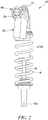
- FIG. 1 is a front view illustrating an entire configuration of a shock absorber according to an embodiment.
- FIG. 2 is a side view of the shock absorber when seen from a different angle.
- FIG. 3 is a cross-sectional view illustrating an entire configuration of the shock absorber.
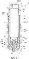
- FIG. 4 is an enlarged cross-sectional view of the shock absorber illustrated in FIG. 3 .
- a shock absorber 10 is provided between a vehicle body of a motorcycle and a rear wheel supporting portion that supports the rear wheel so as to absorb impact or vibration input from the rear wheel.
- the shock absorber 10 extends in an up-down direction, for example, a vehicle body-side attachment member 10t provided at an upper end of the shock absorber 10 is connected to a vehicle body side, and a vehicle shaft-side attachment member 10b provided at a lower end of the shock absorber 10 is connected to a rear wheel side.
- the present invention does not exclude a case in which the shock absorber 10 is provided so as to extend in a lateral direction (approximately a horizontal direction), for example.
- the shock absorber 10 includes a cylinder 11, a piston 12 (see FIG. 3 ), a piston rod 13, a reservoir 30, a damping force generator (a damping force generating unit) 40, and a spring 14.
- the cylinder 11 includes an inner tube 20 and an outer tube 21 that form a concentric double-wall tube.
- the outer diameter of the inner tube 20 is formed to be a predetermined size smaller than the inner diameter of the outer tube 21. In this way, a cylindrical annular passage 101 is formed between the inner tube 20 and the outer tube 21.
- a damper case 15 in which the vehicle body-side attachment member 10t is provided is disposed on an upper end side of the shock absorber 10.
- a cylindrical cylinder holding portion 16 extending toward the cylinder 11 is provided in the damper case 15.
- the outer tube 21 is held in a state in which an upper end 21t of the outer tube 21 is inserted in the cylinder holding portion 16.
- the inner tube 20 is held in a state in which an upper end 20t of the inner tube 20 extends upward further than the upper end 21t of the outer tube 21 and is inserted into an inner tube holding recess 18 formed in the damper case 15.
- the inner tube holding recess 18 has such an inner diameter that the upper end 20t of the inner tube 20 is inserted in the inner tube holding recess 18.
- the inner tube holding recess 18 has an abutting surface 18t on which the upper end 20t of the inner tube 20 abuts and the inner tube holding recess 18 fixes the inner tube 20 in a state in which movement toward the upper side (toward the vehicle body-side attachment member 10t) of the inner tube 20 is restrained.
- the outer tube 21 has the upper end 21t, positioned closer to the piston rod 13, which is disposed on the lower side of the upper end 20t of the inner tube 20.
- the outer tube 21 is formed so that the lower end 21b thereof protrudes downward further than the lower end 20b of the inner tube 20 to a predetermined extent.
- a rod guide 25 is provided on the inner side of the lower end 21b of the outer tube 21.
- the rod guide 25 includes a plate portion 25p that makes contact with an inner circumferential surface of the outer tube 21 to block the inner side of the lower end 21b of the outer tube 21 and a tubular portion 25t that extends toward the damper case 15 from the upper surface of the plate portion 25p.
- the plate portion 25p and the tubular portion 25t are integrated with each other.
- the tubular portion 25t of the rod guide 25 is inserted in the lower end 20b of the inner tube 20 to thereby hold the lower end 20b of the inner tube 20 so as to be immovable in a direction crossing the central axis thereof.
- the plate portion 25p of the rod guide 25 blocks the annular passage 101 between the outer tube 21 and the lower end 20b of the inner tube 20.
- the rod guide 25 has an insertion hole 25h which passes through the plate portion 25p and the tubular portion 25t and through which the piston rod 13 is inserted so that the piston rod 13 is guided so as to be slidable in the central axis direction.
- a rebound rubber 26, which absorbs the impact of the piston 12 colliding, is provided on the inner side of the tubular portion 25t of the rod guide 25.
- the piston 12 is connected to an upper end (one end) 13a of the piston rod 13 by a nut 27.
- the piston 12 is provided on the inner side of the inner tube 20 of the cylinder 11 together with the piston rod 13 so as to be slidable along the central axis direction (the up-down direction) of the inner tube 20.
- the piston 12 partitions the inner space of the inner tube 20 of the cylinder 11 into a piston-side oil chamber S1 formed closer to the damper case 15 on the opposite side to the piston rod 13 and a rod-side oil chamber S2 formed closer to the piston rod 13.
- the piston rod 13 of which the upper end 13a is connected to the piston 12 extends downward along the central axis direction of the inner tube 20, passes through the rod guide 25, and protrudes outside the cylinder 11.
- the vehicle shaft-side attachment member 10b is provided at the lower end 13b of the piston rod 13.
- a bump rubber 28 for preventing full compression of the shock absorber 10 is provided on the vehicle shaft-side attachment member 10b closer to the cylinder 11 in a state of being inserted in the piston rod 13.
- a compression-side communication path 102 having one open end is formed in the damper case 15 at a position facing the opening of the upper end 20t of the inner tube 20.
- the compression-side communication path 102 allows the piston-side oil chamber S1 to communicate with a first oil chamber S11 (see FIG. 5 ) of the damping force generator 40 to be described later.
- a plurality of oil holes 103 is formed in the lower end 20b of the inner tube 20 at intervals in the circumferential direction. Due to these oil holes 103, the rod-side oil chamber S2 and the annular passage 101 communicate with each other.
- An extension-side communication path 105 having one open end is formed in the damper case 15 on the upper side of the upper end 21t of the outer tube 21.
- the extension-side communication path 105 allows the annular passage 101 to communicate with a third oil chamber S13 (see FIG. 5 ) of the damping force generator 40 to be described later.
- a reservoir 30 is formed integrally with the damper case 15 and has a cylindrical form, for example, and a bag-shaped bladder 31 is provided therein.
- the bladder 31 is formed in a bag form using an elastic member such as rubber and can expand and contract. Gas such as air is filled in the bladder 31.
- a space on the outer side of the bladder 31 in the reservoir 30 is configured as an oil storage chamber S3 and communicates with a second oil chamber S12 (see FIG. 5 ) of the damping force generator 40 to be described later through a reservoir communication path 107.
- Oil which is fluid is filled in the piston-side oil chamber S1 and the rod-side oil chamber S2 in the above-described cylinder 11, the annular passage 101 between the inner tube 20 and the outer tube 21, the oil storage chamber S3 in the reservoir 30, and the damping force generator 40 to be described later.
- FIG. 5 is a cross-sectional view illustrating the damping force generator provided in the damper case.
- the damping force generator 40 is configured so that a damper unit 41 is detachably attached to a damper cylinder 29 having a bottomed cylindrical form, formed integrally with the damper case 15.
- the damper unit 41 generally has a columnar form and mainly includes a holder member 42, an outer cap 43, a main damper 60, and a damping adjustment portion 80.
- the holder member 42 integrally has a shaft portion 45 formed in a predetermined length portion c closer to one end 42a and having a fixed outer diameter, and a large diameter portion 46 formed closer to the other end 42b and having a larger outer diameter than the shaft portion 45.
- a recess 47 depressed from the other end 42b side toward one end 42a side is formed in the large diameter portion 46.
- a central hole 48 that is open to one end 42a and the recess 47 is formed in the holder member 42 continuously in the direction of the central axis C of the shaft portion 45.
- a plurality of holes 46h through which the recess 47 on the inner side in the radial direction communicates with the outer side in the radial direction is formed in the large diameter portion 46 at intervals in the circumferential direction.
- the outer cap 43 has a ring form is screwed and attached to the outer circumferential surface of the large diameter portion 46.
- the outer cap 43 is provided so as to block an opening 29a of the damper cylinder 29, and movement of the outer cap 43 in a direction of being removed from the damper cylinder 29 is restricted by a C-ring 49 attached to the inner circumferential surface of the opening 29a.
- a compression-side outlet check valve 61 In the main damper 60, a compression-side outlet check valve 61, an extension-side piston 62, an extension-side damping valve 63, an intermediate member 64, a compression-side valve 65, a compression-side piston 66, an extension-side outlet check valve 67, and a stopper plate 68 are sequentially arranged from the large diameter portion 46 side of the holder member 42 to the one end 42a side thereof.
- the compression-side outlet check valve 61, the extension-side piston 62, the extension-side damping valve 63, the intermediate member 64, the compression-side valve 65, the compression-side piston 66, the extension-side outlet check valve 67, and the stopper plate 68 are formed in a ring form, and the shaft portion 45 of the holder member 42 is inserted through the central portion of these components.
- extension-side inlet ports (extension-side ports) 62t and a plurality of compression-side outlet ports 62c are alternately formed in the extension-side piston 62 along the circumferential direction.
- the extension-side inlet port 62t and the compression-side outlet port 62c are formed so as to pass through the extension-side piston 62 in the direction of the central axis C.
- the extension-side damping valve 63 is provided so as to block an outlet of the extension-side inlet port 62t closer to the intermediate member 64.
- the extension-side damping valve 63 is formed by stacking a plurality of disc valves 63v.
- the compression-side outlet check valve 61 is formed of a disc valve 61v and is provided so as to block an outlet of the compression-side outlet port 62c closer to the large diameter portion 46.
- a plurality of compression-side inlet ports (compression-side ports) 66c and a plurality of extension-side outlet ports 66t are alternately formed in the compression-side piston 66 along the circumferential direction.
- the compression-side inlet port 66c and the extension-side outlet port 66t are formed so as to pass through the compression-side piston 66 in the direction of the central axis C.
- the compression-side valve 65 is provided so as to block an outlet of the compression-side inlet port 66c closer to the intermediate member 64.
- the compression-side valve 65 is formed by stacking a plurality of disc valves 65v.
- the extension-side outlet check valve 67 is formed of a disc valve 67v and is provided so as to block an outlet of the extension-side outlet port 66t closer to the stopper plate 68.
- the intermediate member 64 is disposed between the extension-side damping valve 63 and the compression-side valve 65.
- a plurality of passages 64h through which the inner side in the radial direction communicates with the outer side in the radial direction is formed in the intermediate member 64 continuously in the radial direction at intervals in the circumferential direction.
- a passage 70 extending from the central hole 48 toward the outer side in the radial direction is formed in the shaft portion 45 of the holder member 42 at a position communicating with the respective passages 64h of the intermediate member 64.
- the extension-side damping valve 63 and the compression-side valve 65 are configured to block the compression-side inlet port 66c and the extension-side inlet port 62t to block the flow of oil at normal times.
- the extension-side damping valve 63 and the compression-side valve 65 are bent according to the pressure of oil passing through the compression-side inlet port 66c and the extension-side inlet port 62t and generate damping force when oil passes through the gap between the compression-side inlet port 66c and the extension-side inlet port 62t.
- the extension-side damping valve 63 and the compression-side valve 65 adjust the generated damping force by adjusting the number of disc valves 63v and 65v.
- the compression-side outlet check valve 61 and the extension-side outlet check valve 67 block the flow of oil by blocking the compression-side outlet port 62c and the extension-side outlet port 66t at normal times and are bent according to the pressure of the oil passing through the compression-side outlet port 62c and the extension-side outlet port 66t to circulate oil.
- the stopper plate 68 is disposed closer to one end 42a of the shaft portion 45 of the holder member 42 in relation to the extension-side outlet check valve 67.
- a nut member 69 is screwed to a screw groove 45n formed at one end 42a of the shaft portion 45, and the compression-side outlet check valve 61, the extension-side piston 62, the extension-side damping valve 63, the intermediate member 64, the compression-side valve 65, the compression-side piston 66, the extension-side outlet check valve 67, and the stopper plate 68 are sandwiched between the nut member 69 and the large diameter portion 46 of the holder member 42.
- the damping adjustment portion 80 includes a compression-side adjustment valve 81, a compression-side adjuster 82, an extension-side adjustment valve 83, and an extension-side adjuster 84.
- the compression-side adjustment valve 81 has a distal end inserted into the central hole 48 from the recess 47 formed in the large diameter portion 46 of the holder member 42, and has a base end (the other end 42b) coupled with a disc-shaped end piece 81b within the recess 47.
- the compression-side adjustment valve 81 has an outer diameter smaller than the inner diameter of the central hole 48. Due to this, a gap passage 85 is formed between the inner circumferential surface of the central hole 48 and the outer circumferential surface of the compression-side adjustment valve 81. Moreover, the compression-side adjustment valve 81 has a valve portion 81v which is provided at a distal end (one end 42a) side and of which the outer diameter decreases gradually toward the distal end. A throttle portion 71 of which the inner diameter is narrowed is formed in the central hole 48 closer to one end 42a of the holder member 42 than the passage 70, and the valve portion 81v is inserted in the throttle portion 71.
- the compression-side adjuster 82 is held on an inner cap 87 attached to the inner side of the outer cap 43 so as to be rotatable around the central axis.
- the compression-side adjuster 82 extends into the recess 47 and engages with the end piece 81b.
- Abase portion 82a of the compression-side adjuster 82 is exposed to the outer side from the inner cap 87.
- the end piece 81b advances and retracts in the direction of the central axis C along the compression-side adjuster 82.
- the valve portion 81v of the compression-side adjustment valve 81 advances and retracts in relation to the throttle portion 71 to increase and decrease the gap between the throttle portion 71 and the valve portion 81v.
- the extension-side adjustment valve 83 includes a tubular valve portion 83v which is provided in the recess 47 so as to extend toward an opening closer to the recess 47 of the central hole 48.
- the valve portion 83v is integrated with the extension-side adjustment valve 83.
- the compression-side adjustment valve 81 is inserted into the extension-side adjustment valve 83.
- the extension-side adjuster 84 is held on the inner cap 87 attached to the inner side of the outer cap 43 so as to be rotatable around the central axis.
- the extension-side adjuster 84 extends into the recess 47 and engages with the extension-side adjustment valve 83.
- a base portion 84a of the extension-side adjuster 84 is exposed to the outer side from the inner cap 87.
- the extension-side adjustment valve 83 advances and retracts in the direction of the central axis C.
- the valve portion 83v of the extension-side adjustment valve 83 advances and retracts in relation to the opening of the central hole 48 to increase and decrease the gap between the valve portion 83v and the gap passage 85.
- the extension-side piston 62 and the compression-side piston 66 are formed of a piston member 75 to be described below.
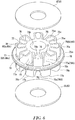
- FIG. 6 is a perspective view illustrating a piston member that forms the extension-side piston 62 and the compression-side piston 66.
- the piston member 75 integrally includes inner circumferential walls 75i, outer circumferential walls 75o formed on the outer side in the radial direction of the inner circumferential wall 75i, and a plurality of connection walls 75w formed at intervals in the circumferential direction so as to extend in the radial direction to connect the inner circumferential walls 75i and the outer circumferential walls 75o.
- An insertion hole 75h in which the shaft portion 45 of the holder member 42 is inserted is formed on the inner side of the inner circumferential walls 75i.
- a protruding wall 75m that protrudes toward the outer side in the radial direction is formed on the outer circumferential surface of the outer circumferential wall 75o continuously in the circumferential direction.
- a sealing ring 76 that abuts on the inner circumferential surface of the damper cylinder 29 to seal the space between the piston member 75 and the inner circumferential surface of the damper cylinder 29 is provided on the outer circumferential surface of the protruding wall 75m.
- a first port 77 and a second port 78 are alternately formed in the piston member 75 along the circumferential direction between the inner circumferential wall 75i and the outer circumferential wall 75o.
- the first and second ports 77 and 78 are formed between the connection walls 75w, adjacent to each other in the circumferential direction.
- the first and second ports 77 and 78 pass in the direction of connecting one end 75a of the piston member 75 and the other end 75b.
- the first port 77 forms the extension-side inlet port 62t or the compression-side inlet port 66c
- the second port 78 forms the compression-side outlet port 62c or the extension-side outlet port 66t.
- the first port 77 has a port inlet 77a provided closer to one end 75a and a port outlet 77b provided closer to the other end 75b.
- a notch 75k is formed in the outer circumferential wall 75o on the side closer to one end 75a whereby a port inlet opening (a compression-side port inlet portion) 79A that is open to the outer side in the radial direction is formed in the first port 77.
- the second port 78 has a port inlet 78a provided closer to the other end 75b and a port outlet 78b provided closer to one end 75a.
- a notch 75j is formed in the outer circumferential wall 75o on the side closer to the other end 75b whereby a port inlet opening (a compression-side outlet port inlet portion) 79B that is open to the outer side in the radial direction is formed in the second port 78.
- the inner space of the damper cylinder 29 is partitioned into the first oil chamber S11, the second oil chamber S12, and the third oil chamber S13 by the sealing ring 76 of the piston member 75 that forms the compression-side piston 66 and the sealing ring 76 of the piston member 75 that forms the extension-side piston 62.
- the first oil chamber S11 is formed closer to one end 42a of the holder member 42 than the sealing ring 76 of the compression-side piston 66 and communicates with the piston-side oil chamber S1 (see FIG. 4 ) through the compression-side communication path 102.
- the second oil chamber S12 is formed between the sealing ring 76 of the compression-side piston 66 and the sealing ring 76 of the extension-side piston 62 and communicates with the oil storage chamber S3 (see FIG. 4 ) of the reservoir 30 through the reservoir communication path 107.
- the third oil chamber S13 is formed between the sealing ring 76 of the extension-side piston 62 and the outer cap 43 and communicates with the annular passage 101 (see FIG. 4 ) of the cylinder 11 through the extension-side communication path 105.
- the central hole 48 formed in the holder member 42 is open to the inner space of the first oil chamber S11 at one end 42a of the holder member 42.
- the passage 64h formed in the intermediate member 64 is open to the inner space of the second oil chamber S12.
- the hole 46h formed in the large diameter portion 46 of the holder member 42 is open to the inner space of the third oil chamber S13.
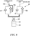
- FIG. 7 is a diagram schematically illustrating the configuration of the shock absorber described above.
- the oil delivered to the first oil chamber S11 flows into the compression-side inlet port 66c from the port inlet opening 79A formed in the compression-side piston 66 of the main damper 60 to push and open the compression-side valve 65 provided on the outlet side of the compression-side inlet port 66c and flows toward the second oil chamber S12.
- the oil pushes and opens the compression-side valve 65 to pass through the gap between the compression-side valve 65 and the outlet of the compression-side inlet port 66c whereby damping force is generated.
- a portion of the oil delivered to the first oil chamber S11 flows into the central hole 48 open to one end 42a of the holder member 42 to pass through the gap between the throttle portion 71 and the valve portion 81v of the compression-side adjustment valve 81 and flows into the second oil chamber S12 through the passage 70 formed in the shaft portion 45 and the passage 64h formed in the intermediate member 64.
- damping force is generated.
- a portion of the oil flowing into the second oil chamber S12 flows into the oil storage chamber S3 through the reservoir communication path 107 formed in the damper case 15 in order to compensate for a change in the volume of the piston rod 13 in the cylinder 11 according to the movement of the piston 12. Moreover, a remaining portion of the oil flowing into the second oil chamber S12 flows into the compression-side outlet port 62c from the port inlet opening 79B of the extension-side piston 62 to push and open the compression-side outlet check valve 61 and flows into the third oil chamber S13.
- the oil flowing into the third oil chamber S13 flows into the rod-side oil chamber S2 through the extension-side communication path 105, the annular passage 101 of the cylinder 11, and the plurality of oil holes 103.
- the oil delivered to the third oil chamber S13 flows into the extension-side inlet port 62t from the port inlet opening 79A of the extension-side piston 62 to push and open the extension-side damping valve 63 provided on the outlet side of the extension-side inlet port 62t whereby damping force is generated.
- the oil having passed through the gap between the extension-side inlet port 62t and the extension-side damping valve 63 flows toward the second oil chamber S12.
- the oil flows from the oil storage chamber S3 into the second oil chamber S12 through the reservoir communication path 107 formed in the damper case 15 in order to compensate for a change in the volume of the piston rod 13 in the cylinder 11 according to the movement of the piston 12.
- the oil having flowed into the second oil chamber S12 passes through the extension-side outlet port 66t from the port inlet opening 79B of the compression-side piston 66 to push and open the extension-side outlet check valve 67 and flows into the first oil chamber S11.
- the oil in the first oil chamber S11 is delivered to the piston-side oil chamber S1 through the compression-side communication path 102 formed in the damper case 15.
- the cross-sectional area AO of the reservoir communication path 107 is smaller than the total cross-sectional area A1 of the plurality of compression-side inlet ports 66c having the compression-side valve 65 that generates damping force.
- the cross-sectional area A2 of the compression-side communication path 102 is equal to or larger than the cross-sectional area A1 of the compression-side inlet port 66c.
- the cross-sectional area A3 between the compression-side piston 66 and the damper cylinder 29 into which the oil flows from the compression-side communication path 102 is equal to or larger than the total cross-sectional area A1 of the compression-side inlet port 66c and is equal to or smaller than the cross-sectional area A2 of the compression-side communication path 102.
- a total opening area A4 of the plurality of port inlet openings 79A is larger than the total cross-sectional area A1 of the plurality of compression-side inlet ports 66c.
- a passage cross-sectional area of a compression-side oil passage system that extends from the piston-side oil chamber S1 to reach the second oil chamber S12 gradually decreases without increasing in the halfway of the passage. Furthermore, since the cross-sectional area A0 of the reservoir communication path 107 is smaller than the total cross-sectional area A1 of the plurality of compression-side inlet ports 66c, the cross-sectional area A0 of the reservoir communication path 107 is the smallest.
- the cross-sectional area A11 of the extension-side communication path 105 is larger than the cross-sectional area A0 of the reservoir communication path 107.
- the cross-sectional area A14 between the damper cylinder 29 and the extension-side piston 62 is larger than the cross-sectional area A0 of the reservoir communication path 107.
- the total cross-sectional area A15 of the plurality of compression-side outlet ports 62c is equal to or larger than the cross-sectional area A14 between the damper cylinder 29 and the extension-side piston 62. Furthermore, the total opening area A16 of the plurality of port inlet openings 79B is equal to or larger than the total cross-sectional area A15 of the plurality of compression-side outlet ports 62c.
- the cross-sectional area A12 of the annular passage 101 is equal to or larger than the cross-sectional area A11 of the extension-side communication path 105.
- the total cross-sectional area A13 of the plurality of oil holes 103 is equal to or larger than the cross-sectional area A12 of the annular passage 101.
- the cross-sectional area A0 of the reservoir communication path 107, the total cross-sectional area A1 of the compression-side inlet port 66c, the cross-sectional area A2 of the compression-side communication path 102, the cross-sectional area A3 between the damper cylinder 29 and the compression-side piston 66, the total opening area A4 of the port inlet openings 79A, the cross-sectional area A11 of the extension-side communication path 105, the cross-sectional area A14 between the damper cylinder 29 and the extension-side piston 62, the total cross-sectional area A15 of the compression-side outlet ports 62c, and the total opening areas A16 of the port inlet openings 79B are the cross-sectional areas of the smallest-diameter portions of the passages.
- the shock absorber 10 of the present embodiment by setting the cross-sectional area A0 of the reservoir communication path 107 to be smaller than the cross-sectional area A1 of the compression-side inlet port 66c, oil does not easily flow into the reservoir 30 when an excessive input acts during the compression-side operation. In this way, after oil flows from the piston-side oil chamber S1 to the damping force generator 40 through the compression-side communication path 102 and damping force is generated in the compression-side inlet port 66c, the oil flows smoothly toward the piston-side oil chamber S1. As a result, the shock absorber 10 can exhibit its original damping characteristics even when oil flows at a high flow speed, for example.
- An oil passage system that extends from the piston-side oil chamber S1 to reach the second oil chamber S12 in the compression-side operation is configured so that the cross-sectional area A2 of the compression-side communication path 102, the cross-sectional area A3 between the damper cylinder 29 and the compression-side piston 66, the total opening areas A4 of the plurality of port inlet openings 79A, and the total cross-sectional area A1 of the plurality of compression-side inlet ports 66c satisfy the relation of A2 ⁇ A3 ⁇ A4 ⁇ A1. That is, the passage cross-sectional area of the compression-side oil passage system extending from the piston-side oil chamber S1 to reach the second oil chamber S12 gradually decreases without increasing in the halfway of the passage.
- the cross-sectional area A0 of the reservoir communication path 107 is smaller than the total cross-sectional area A1 of the plurality of compression-side inlet ports 66c, the cross-sectional area A0 of the reservoir communication path 107 is the smallest.
- An oil passage system that extends from the second oil chamber S12 to return to the rod-side oil chamber S2 in the compression-side operation is configured so that the cross-sectional area A0 of the reservoir communication path 107, the cross-sectional area A14 between the damper cylinder 29 and the extension-side piston 62, the total opening area A16 of the plurality of port inlet openings 79B, the total cross-sectional area A15 of the plurality of compression-side outlet ports 62c, the cross-sectional area A11 of the extension-side communication path 105, the cross-sectional area A12 of the annular passage 101, and the cross-sectional area A13 of the oil hole 103 satisfy the relation of A0 ⁇ A14 ⁇ A16 ⁇ A15 ⁇ A11 ⁇ A12 ⁇ A13.
- FIG. 8 is a diagram conceptually illustrating an oil flow speed distribution when an excessive input acts on the shock absorber in a compression-side cycle and oil flows at a high speed.
- the thickness of an arrow indicates the flow speed of oil.
- the shock absorber 10 by configuring the shock absorber 10 so that the cross-sectional area A0 of the reservoir communication path 107 is the smallest as described above, oil does not easily flow into the reservoir 30 when an excessive input acts during the compression-side operation. In this way, after oil flows from the piston-side oil chamber S1 into the damping force generator 40 through the compression-side communication path 102 and damping force is generated in the compression-side inlet port 66c, the oil smoothly flows toward the piston-side oil chamber S1 through an extension-side passage. As a result, the shock absorber 10 can exhibit its original damping characteristics even when oil flows at a high flow speed.
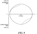
- FIG. 9 is a diagram illustrating damping characteristics as the relation between stroke and load when an excessive input acts on the shock absorber in the compression-side cycle and oil flows at a high speed.
- the damping characteristics are distorted when the shock absorber operates at a high speed due to an excessive input as indicated by a two-dot chain line in FIG. 9 .
- the shock absorber 10 having the configuration of the present embodiment even when the shock absorber operates at a high speed due to an excessive input, it is possible to suppress deformation of damping characteristics and to obtain satisfactory damping characteristics.
- shock absorber of the present invention is not limited to the embodiment described above with reference to the drawings, and various modifications may occur within the technical scope thereof.
- the configuration of the damping adjustment portion 80 provided in the damping force generator 40 is not particularly limited, and the damping adjustment portion 80 may be omitted.
- extension-side piston 62 and the compression-side piston 66 are formed of the piston member 75, the present invention is not limited to this. Any one of the extension-side piston 62 and the compression-side piston 66 may be formed alone of the piston member 75. Moreover, the compression-side inlet port 66c only may include the port inlet opening 79A that is open to the outer side in the radial direction.
- the entire configuration of the shock absorber 10 can be changed appropriately.
Landscapes
- Engineering & Computer Science (AREA)
- General Engineering & Computer Science (AREA)
- Mechanical Engineering (AREA)
- Fluid-Damping Devices (AREA)
- Axle Suspensions And Sidecars For Cycles (AREA)
Claims (9)
- Amortisseur de chocs comprenant :un cylindre (11) qui comporte un tube externe (21) et un tube interne (20) prévu sur un côté interne du tube externe (21) dans une direction radiale à un intervalle du tube externe (21), et dans lequel de l'huile est renfermée hermétiquement ;une tige de piston (13) dont une extrémité est insérée dans le cylindre (11) et l'autre extrémité est étendue à l'extérieur du cylindre (11) ;un piston (12) qui est relié à l'extrémité de la tige de piston (13) et est prévu dans le tube interne (20) de façon à être apte à coulisser le long d'une direction d'axe central du tube interne (20), et lequel sépare un espace interne du tube interne (20) en une chambre à huile côté tige (S2) plus proche de la tige de piston (13) et une chambre à huile côté piston (S1) d'un côté opposé à la tige de piston (13) ;une unité de génération de force d'amortissement qui régule l'écoulement de l'huile se produisant lorsque le piston (12) coulisse dans le tube interne (20) selon un déplacement de la tige de piston (13), pour générer une force d'amortissement ;un réservoir (30) qui compense l'huile selon un changement de volume d'avancée de la tige de piston (13) dans le cylindre (11) ;une voie de communication avec le réservoir (107) à travers laquelle l'unité de génération de force d'amortissement et le réservoir (30) communiquent l'un avec l'autre ;une voie de communication côté compression (102) à travers laquelle la chambre à huile côté piston (S1) et l'unité de génération de force d'amortissement communiquent l'une avec l'autre ; etun orifice côté compression qui est prévu dans l'unité de génération de force d'amortissement, dans lequel l'huile s'écoule à partir de la voie de communication côté compression (102), et qui comporte une vanne côté compression (65) qui génère la force d'amortissement,dans lequel une superficie en coupe la plus petite (A0) de la voie de communication avec le réservoir (107) est plus petite qu'une superficie en coupe la plus petite (A1) de l'orifice côté compression caractérisé parune voie de communication côté extension (105) à travers laquelle l'unité de génération de force d'amortissement et un passage annulaire (101) formé entre le tube externe (21) et le tube interne (20) communiquent l'un avec l'autre,dans lequel une superficie en coupe la plus petite (A11) de la voie de communication côté extension (105) est plus grande que la superficie en coupe la plus petite (A0) de la voie de communication avec le réservoir (107).
- Amortisseur de chocs selon la revendication 1,
dans lequel une superficie en coupe la plus petite (A2) de la voie de communication côté compression (102) est égale à ou plus grande que la superficie en coupe la plus petite (A1) de l'orifice côté compression. - Amortisseur de chocs selon la revendication 1
dans lequel l'unité de génération de force d'amortissement inclut :un piston côté compression (66) comportant l'orifice côté compression ; etun cylindre d'amortisseur (29) qui accueille le piston côté compression (66), etdans lequel une superficie en coupe la plus petite (A3) entre le piston côté compression (66) et le cylindre d'amortisseur (29) dans lequel l'huile s'écoule à partir de la voie de communication côté compression (102) est égale à ou plus grande que la superficie en coupe la plus petite (A1) de l'orifice côté compression et est égale à ou plus petite que la superficie en coupe la plus petite (A2) de la voie de communication côté compression (102). - Amortisseur de chocs selon la revendication 3,
dans lequel une partie d'entrée de l'orifice côté compression est formée dans le piston côté compression (66) d'un côté entrée de l'orifice côté compression de façon à être ouverte vers une surface circonférentielle externe du piston côté compression (66), et
dans lequel une superficie d'ouverture (A4) de la partie d'entrée de l'orifice côté compression est plus grande que la superficie en coupe la plus petite (A1) de l'orifice côté compression. - Amortisseur de chocs selon la revendication 1,
dans lequel la superficie en coupe la plus petite (A12) du passage annulaire (101) est égale à ou plus grande que la superficie en coupe la plus petite (A11) de la voie de communication côté extension (105). - Amortisseur de chocs selon la revendication 1, comprenant en outre :un trou d'huile (103) qui est formé dans le tube interne (20) de façon à permettre une communication entre le passage annulaire (101) et la chambre à huile côté tige (S2),dans lequel une superficie en coupe (A13) du trou d'huile (103) est égale à ou plus grande que la superficie en coupe la plus petite (A12) du passage annulaire (101).
- Amortisseur de chocs selon la revendication 1,
dans lequel l'unité de génération de force d'amortissement inclut en outre :un piston côté extension (62) comportant un orifice côté extension dans lequel l'huile s'étant écoulée depuis la voie de communication côté extension (105) dans l'unité de génération de force d'amortissement s'écoule ; etun orifice de sortie côté compression (62c) dans lequel l'huile étant passée à travers l'orifice côté compression du piston côté compression (66) s'écoule,dans lequel une superficie en coupe la plus petite (A14) entre le cylindre d'amortisseur (29) et le piston côté extension (62) est plus grande que la superficie en coupe la plus petite (A0) de la voie de communication avec le réservoir (107). - Amortisseur de chocs selon la revendication 7,
dans lequel la superficie en coupe la plus petite (A15) de l'orifice de sortie côté compression (62c) est égale à ou plus grande que la superficie en coupe la plus petite (A14) entre le cylindre d'amortisseur (29) et le piston côté extension (62). - Amortisseur de chocs selon la revendication 7,
dans lequel une partie d'entrée d'orifice de sortie côté compression est formée dans le piston côté extension (62) d'un côté entrée de l'orifice de sortie côté compression (62c) de façon à être ouverte vers une surface circonférentielle externe du piston côté extension (62), et
dans lequel une superficie d'ouverture (A16) de la partie d'entrée d'orifice de sortie côté compression est plus grande qu'une superficie en coupe la plus petite (A15) de l'orifice de sortie côté compression (62c).
Applications Claiming Priority (1)
| Application Number | Priority Date | Filing Date | Title |
|---|---|---|---|
| JP2016069674A JP6628146B2 (ja) | 2016-03-30 | 2016-03-30 | 緩衝器 |
Publications (2)
| Publication Number | Publication Date |
|---|---|
| EP3236104A1 EP3236104A1 (fr) | 2017-10-25 |
| EP3236104B1 true EP3236104B1 (fr) | 2020-04-01 |
Family
ID=58094291
Family Applications (1)
| Application Number | Title | Priority Date | Filing Date |
|---|---|---|---|
| EP17156861.1A Active EP3236104B1 (fr) | 2016-03-30 | 2017-02-20 | Amortisseur de chocs |
Country Status (3)
| Country | Link |
|---|---|
| US (1) | US10145438B2 (fr) |
| EP (1) | EP3236104B1 (fr) |
| JP (1) | JP6628146B2 (fr) |
Families Citing this family (13)
| Publication number | Priority date | Publication date | Assignee | Title |
|---|---|---|---|---|
| JP6946161B2 (ja) * | 2017-12-06 | 2021-10-06 | Kybモーターサイクルサスペンション株式会社 | 緩衝器 |
| US11143260B2 (en) | 2018-12-28 | 2021-10-12 | Tenneco Automotive Operating Company Inc. | Damper with single external control valve |
| US11454291B2 (en) * | 2018-12-28 | 2022-09-27 | Tenneco Automotive Operating Company Inc. | Damper with control valves |
| US11156261B2 (en) | 2018-12-28 | 2021-10-26 | Tenneco Automotive Operating Company Inc. | Damper with multiple external control valves |
| US11118649B2 (en) | 2019-07-01 | 2021-09-14 | Tenneco Automotive Operating Company Inc. | Damper with side collector and external control valves |
| US11635122B2 (en) | 2019-07-18 | 2023-04-25 | Tenneco Automotive Operating Company Inc. | Intake device for a damper having a side collector |
| US11248677B2 (en) | 2019-07-18 | 2022-02-15 | Tenneco Automotive Operating Company Inc. | Pre-assembled piston accumulator insert device |
| US11441633B2 (en) * | 2020-08-14 | 2022-09-13 | DRiV Automotive Inc. | Damper assembly including intake valve in fluid chamber |
| CN112594247B (zh) * | 2020-12-24 | 2023-05-02 | 广州风神汽车有限公司 | 一种双向阻尼缓冲油缸 |
| DE102021202418B4 (de) * | 2021-03-12 | 2025-01-02 | Thyssenkrupp Ag | Mehrrohrschwingungsdämpfer mit verstellbarer Dämpfkraft für ein Fahrzeug |
| TWI784475B (zh) * | 2021-04-12 | 2022-11-21 | 廖志賢 | 全方位油管活動接頭及含有其的避震器 |
| CN114483854A (zh) * | 2022-01-26 | 2022-05-13 | 深圳扬宁汽车配件有限公司 | 减震器及汽车 |
| DE102022209324A1 (de) * | 2022-09-07 | 2024-03-07 | Thyssenkrupp Ag | Schwingungsdämpfer |
Family Cites Families (27)
| Publication number | Priority date | Publication date | Assignee | Title |
|---|---|---|---|---|
| US4153237A (en) * | 1976-11-01 | 1979-05-08 | Supalla Steven A | Hydrapneumatic suspension unit and valving structure |
| DE2855561A1 (de) * | 1978-12-22 | 1980-07-10 | Fichtel & Sachs Ag | Federbein oder stossdaempfer fuer fahrzeuge mit druckanschlag |
| NL8600211A (nl) * | 1986-01-30 | 1987-08-17 | White Power Prod Bv | Hydraulische schokdemper. |
| SE9602507L (sv) * | 1996-06-25 | 1997-12-26 | Oehlins Racing Ab | Stötdämpare |
| US5957252A (en) * | 1996-08-02 | 1999-09-28 | Berthold; Brian D. | Hydraulic suspension unit |
| IT1293262B1 (it) * | 1997-07-23 | 1999-02-16 | Marzocchi Spa | Ammortizzatore idraulico,con compensatore esterno a posizione regolabile |
| JP2006038098A (ja) * | 2004-07-27 | 2006-02-09 | Hitachi Ltd | 油圧緩衝器 |
| DE102006025826B4 (de) * | 2005-07-26 | 2014-10-23 | Zf Friedrichshafen Ag | Selbstpumpendes hydropneumatisches Federbein |
| JP4967091B2 (ja) * | 2007-04-19 | 2012-07-04 | 日立オートモティブシステムズ株式会社 | 流体圧緩衝器 |
| SE532115C2 (sv) * | 2007-05-16 | 2009-10-27 | Oehlins Racing Ab | Tryckreservoar till stötdämpare |
| US8857580B2 (en) * | 2009-01-07 | 2014-10-14 | Fox Factory, Inc. | Remotely operated bypass for a suspension damper |
| JP2010101422A (ja) | 2008-10-23 | 2010-05-06 | Aisin Seiki Co Ltd | ショックアブソーバ |
| JP5426431B2 (ja) * | 2009-06-30 | 2014-02-26 | 株式会社ショーワ | 油圧緩衝器 |
| JP2011012806A (ja) | 2010-02-25 | 2011-01-20 | Showa Corp | 油圧緩衝器 |
| US8950558B2 (en) * | 2011-12-29 | 2015-02-10 | Fox Factory, Inc. | Dampers with thermal expansion compensation |
| US9228630B2 (en) * | 2012-08-27 | 2016-01-05 | Cane Creek Cycling Components | Twin tube style damper with selectable bypass flow passages |
| DE102013112739B4 (de) * | 2013-11-19 | 2018-10-04 | Thomas Ripa | Verfahrstufe für einen hydraulischen Stoßdämpfer und Stoßdämpfer mit der Verfahrstufe |
| JP6198601B2 (ja) * | 2013-12-20 | 2017-09-20 | Kyb株式会社 | 緩衝器 |
| JP6154741B2 (ja) * | 2013-12-20 | 2017-06-28 | Kyb株式会社 | 緩衝器 |
| JP6291266B2 (ja) * | 2014-01-27 | 2018-03-14 | 株式会社ショーワ | フロントフォーク |
| US9915313B2 (en) * | 2014-05-12 | 2018-03-13 | Cane Creek Cycling Components | Twin tube damper |
| JP6438258B2 (ja) * | 2014-09-30 | 2018-12-12 | 株式会社ショーワ | 反力調整部材及びサスペンション |
| JP6450135B2 (ja) * | 2014-10-03 | 2019-01-09 | 株式会社ショーワ | ダイヤフラムユニット及びサスペンション |
| JP6482929B2 (ja) * | 2015-03-31 | 2019-03-13 | 株式会社ショーワ | 緩衝器 |
| JP6417281B2 (ja) * | 2015-06-10 | 2018-11-07 | Kyb株式会社 | 緩衝器 |
| JP6577826B2 (ja) * | 2015-10-26 | 2019-09-18 | 株式会社ショーワ | 緩衝器 |
| JP6642207B2 (ja) * | 2016-03-30 | 2020-02-05 | 株式会社ショーワ | 緩衝器、及び減衰力発生装置 |
-
2016
- 2016-03-30 JP JP2016069674A patent/JP6628146B2/ja active Active
-
2017
- 2017-02-16 US US15/434,633 patent/US10145438B2/en active Active
- 2017-02-20 EP EP17156861.1A patent/EP3236104B1/fr active Active
Non-Patent Citations (1)
| Title |
|---|
| None * |
Also Published As
| Publication number | Publication date |
|---|---|
| EP3236104A1 (fr) | 2017-10-25 |
| JP2017180705A (ja) | 2017-10-05 |
| US10145438B2 (en) | 2018-12-04 |
| US20170284497A1 (en) | 2017-10-05 |
| JP6628146B2 (ja) | 2020-01-08 |
Similar Documents
| Publication | Publication Date | Title |
|---|---|---|
| EP3236104B1 (fr) | Amortisseur de chocs | |
| EP3236105B1 (fr) | Amortisseur de chocs | |
| JP4712703B2 (ja) | 衝撃吸収器アセンブリ | |
| US20100236882A1 (en) | Hydraulic shock absorber | |
| BR112017019643B1 (pt) | Amortecedor hidráulico para suspensão de veículo | |
| CN102359531B (zh) | 单筒式减振器 | |
| EP3631233B1 (fr) | Jambe de fourche avant télescopique sous pression, fourche avant et véhicule | |
| EP3236106B1 (fr) | Amortisseur de chocs et générateur de force d'amortissement | |
| CN202251617U (zh) | 单筒式减振器 | |
| CN101134487A (zh) | 前叉 | |
| JP5383451B2 (ja) | 油圧緩衝器 | |
| JP2008057591A (ja) | フロントフォーク | |
| JP6239420B2 (ja) | 油圧緩衝器 | |
| US20090223763A1 (en) | Shock absorber | |
| US11592074B2 (en) | Position-dependent shock absorber | |
| JP2016194338A (ja) | 油圧緩衝器 | |
| KR102714061B1 (ko) | 쇽 업소버 | |
| JP2010038171A (ja) | 油圧緩衝器 | |
| JP2017187048A (ja) | 緩衝器、及び緩衝器の組み立て方法 | |
| JP2011033054A (ja) | 油圧緩衝器のばね荷重調整装置 | |
| CN112292543A (zh) | 前叉 | |
| CN107683377A (zh) | 活塞 | |
| JP2009275813A (ja) | 油圧緩衝器のピストン構造 |
Legal Events
| Date | Code | Title | Description |
|---|---|---|---|
| PUAI | Public reference made under article 153(3) epc to a published international application that has entered the european phase |
Free format text: ORIGINAL CODE: 0009012 |
|
| STAA | Information on the status of an ep patent application or granted ep patent |
Free format text: STATUS: THE APPLICATION HAS BEEN PUBLISHED |
|
| AK | Designated contracting states |
Kind code of ref document: A1 Designated state(s): AL AT BE BG CH CY CZ DE DK EE ES FI FR GB GR HR HU IE IS IT LI LT LU LV MC MK MT NL NO PL PT RO RS SE SI SK SM TR |
|
| AX | Request for extension of the european patent |
Extension state: BA ME |
|
| STAA | Information on the status of an ep patent application or granted ep patent |
Free format text: STATUS: REQUEST FOR EXAMINATION WAS MADE |
|
| 17P | Request for examination filed |
Effective date: 20180125 |
|
| RBV | Designated contracting states (corrected) |
Designated state(s): AL AT BE BG CH CY CZ DE DK EE ES FI FR GB GR HR HU IE IS IT LI LT LU LV MC MK MT NL NO PL PT RO RS SE SI SK SM TR |
|
| STAA | Information on the status of an ep patent application or granted ep patent |
Free format text: STATUS: EXAMINATION IS IN PROGRESS |
|
| 17Q | First examination report despatched |
Effective date: 20181030 |
|
| GRAP | Despatch of communication of intention to grant a patent |
Free format text: ORIGINAL CODE: EPIDOSNIGR1 |
|
| STAA | Information on the status of an ep patent application or granted ep patent |
Free format text: STATUS: GRANT OF PATENT IS INTENDED |
|
| INTG | Intention to grant announced |
Effective date: 20191007 |
|
| RAP1 | Party data changed (applicant data changed or rights of an application transferred) |
Owner name: SHOWA CORPORATION |
|
| GRAS | Grant fee paid |
Free format text: ORIGINAL CODE: EPIDOSNIGR3 |
|
| GRAA | (expected) grant |
Free format text: ORIGINAL CODE: 0009210 |
|
| STAA | Information on the status of an ep patent application or granted ep patent |
Free format text: STATUS: THE PATENT HAS BEEN GRANTED |
|
| AK | Designated contracting states |
Kind code of ref document: B1 Designated state(s): AL AT BE BG CH CY CZ DE DK EE ES FI FR GB GR HR HU IE IS IT LI LT LU LV MC MK MT NL NO PL PT RO RS SE SI SK SM TR |
|
| REG | Reference to a national code |
Ref country code: GB Ref legal event code: FG4D |
|
| REG | Reference to a national code |
Ref country code: AT Ref legal event code: REF Ref document number: 1251735 Country of ref document: AT Kind code of ref document: T Effective date: 20200415 Ref country code: CH Ref legal event code: EP |
|
| REG | Reference to a national code |
Ref country code: DE Ref legal event code: R096 Ref document number: 602017013812 Country of ref document: DE |
|
| REG | Reference to a national code |
Ref country code: IE Ref legal event code: FG4D |
|
| REG | Reference to a national code |
Ref country code: SE Ref legal event code: TRGR |
|
| PG25 | Lapsed in a contracting state [announced via postgrant information from national office to epo] |
Ref country code: BG Free format text: LAPSE BECAUSE OF FAILURE TO SUBMIT A TRANSLATION OF THE DESCRIPTION OR TO PAY THE FEE WITHIN THE PRESCRIBED TIME-LIMIT Effective date: 20200701 |
|
| REG | Reference to a national code |
Ref country code: NL Ref legal event code: MP Effective date: 20200401 |
|
| REG | Reference to a national code |
Ref country code: LT Ref legal event code: MG4D |
|
| PG25 | Lapsed in a contracting state [announced via postgrant information from national office to epo] |
Ref country code: FI Free format text: LAPSE BECAUSE OF FAILURE TO SUBMIT A TRANSLATION OF THE DESCRIPTION OR TO PAY THE FEE WITHIN THE PRESCRIBED TIME-LIMIT Effective date: 20200401 Ref country code: NL Free format text: LAPSE BECAUSE OF FAILURE TO SUBMIT A TRANSLATION OF THE DESCRIPTION OR TO PAY THE FEE WITHIN THE PRESCRIBED TIME-LIMIT Effective date: 20200401 Ref country code: GR Free format text: LAPSE BECAUSE OF FAILURE TO SUBMIT A TRANSLATION OF THE DESCRIPTION OR TO PAY THE FEE WITHIN THE PRESCRIBED TIME-LIMIT Effective date: 20200702 Ref country code: LT Free format text: LAPSE BECAUSE OF FAILURE TO SUBMIT A TRANSLATION OF THE DESCRIPTION OR TO PAY THE FEE WITHIN THE PRESCRIBED TIME-LIMIT Effective date: 20200401 Ref country code: PT Free format text: LAPSE BECAUSE OF FAILURE TO SUBMIT A TRANSLATION OF THE DESCRIPTION OR TO PAY THE FEE WITHIN THE PRESCRIBED TIME-LIMIT Effective date: 20200817 Ref country code: IS Free format text: LAPSE BECAUSE OF FAILURE TO SUBMIT A TRANSLATION OF THE DESCRIPTION OR TO PAY THE FEE WITHIN THE PRESCRIBED TIME-LIMIT Effective date: 20200801 Ref country code: NO Free format text: LAPSE BECAUSE OF FAILURE TO SUBMIT A TRANSLATION OF THE DESCRIPTION OR TO PAY THE FEE WITHIN THE PRESCRIBED TIME-LIMIT Effective date: 20200701 Ref country code: CZ Free format text: LAPSE BECAUSE OF FAILURE TO SUBMIT A TRANSLATION OF THE DESCRIPTION OR TO PAY THE FEE WITHIN THE PRESCRIBED TIME-LIMIT Effective date: 20200401 |
|
| PG25 | Lapsed in a contracting state [announced via postgrant information from national office to epo] |
Ref country code: RS Free format text: LAPSE BECAUSE OF FAILURE TO SUBMIT A TRANSLATION OF THE DESCRIPTION OR TO PAY THE FEE WITHIN THE PRESCRIBED TIME-LIMIT Effective date: 20200401 Ref country code: LV Free format text: LAPSE BECAUSE OF FAILURE TO SUBMIT A TRANSLATION OF THE DESCRIPTION OR TO PAY THE FEE WITHIN THE PRESCRIBED TIME-LIMIT Effective date: 20200401 Ref country code: HR Free format text: LAPSE BECAUSE OF FAILURE TO SUBMIT A TRANSLATION OF THE DESCRIPTION OR TO PAY THE FEE WITHIN THE PRESCRIBED TIME-LIMIT Effective date: 20200401 |
|
| PG25 | Lapsed in a contracting state [announced via postgrant information from national office to epo] |
Ref country code: AL Free format text: LAPSE BECAUSE OF FAILURE TO SUBMIT A TRANSLATION OF THE DESCRIPTION OR TO PAY THE FEE WITHIN THE PRESCRIBED TIME-LIMIT Effective date: 20200401 |
|
| REG | Reference to a national code |
Ref country code: DE Ref legal event code: R097 Ref document number: 602017013812 Country of ref document: DE |
|
| PG25 | Lapsed in a contracting state [announced via postgrant information from national office to epo] |
Ref country code: SM Free format text: LAPSE BECAUSE OF FAILURE TO SUBMIT A TRANSLATION OF THE DESCRIPTION OR TO PAY THE FEE WITHIN THE PRESCRIBED TIME-LIMIT Effective date: 20200401 Ref country code: EE Free format text: LAPSE BECAUSE OF FAILURE TO SUBMIT A TRANSLATION OF THE DESCRIPTION OR TO PAY THE FEE WITHIN THE PRESCRIBED TIME-LIMIT Effective date: 20200401 Ref country code: RO Free format text: LAPSE BECAUSE OF FAILURE TO SUBMIT A TRANSLATION OF THE DESCRIPTION OR TO PAY THE FEE WITHIN THE PRESCRIBED TIME-LIMIT Effective date: 20200401 Ref country code: IT Free format text: LAPSE BECAUSE OF FAILURE TO SUBMIT A TRANSLATION OF THE DESCRIPTION OR TO PAY THE FEE WITHIN THE PRESCRIBED TIME-LIMIT Effective date: 20200401 Ref country code: ES Free format text: LAPSE BECAUSE OF FAILURE TO SUBMIT A TRANSLATION OF THE DESCRIPTION OR TO PAY THE FEE WITHIN THE PRESCRIBED TIME-LIMIT Effective date: 20200401 Ref country code: DK Free format text: LAPSE BECAUSE OF FAILURE TO SUBMIT A TRANSLATION OF THE DESCRIPTION OR TO PAY THE FEE WITHIN THE PRESCRIBED TIME-LIMIT Effective date: 20200401 |
|
| PLBE | No opposition filed within time limit |
Free format text: ORIGINAL CODE: 0009261 |
|
| STAA | Information on the status of an ep patent application or granted ep patent |
Free format text: STATUS: NO OPPOSITION FILED WITHIN TIME LIMIT |
|
| PG25 | Lapsed in a contracting state [announced via postgrant information from national office to epo] |
Ref country code: PL Free format text: LAPSE BECAUSE OF FAILURE TO SUBMIT A TRANSLATION OF THE DESCRIPTION OR TO PAY THE FEE WITHIN THE PRESCRIBED TIME-LIMIT Effective date: 20200401 Ref country code: SK Free format text: LAPSE BECAUSE OF FAILURE TO SUBMIT A TRANSLATION OF THE DESCRIPTION OR TO PAY THE FEE WITHIN THE PRESCRIBED TIME-LIMIT Effective date: 20200401 |
|
| 26N | No opposition filed |
Effective date: 20210112 |
|
| PG25 | Lapsed in a contracting state [announced via postgrant information from national office to epo] |
Ref country code: SI Free format text: LAPSE BECAUSE OF FAILURE TO SUBMIT A TRANSLATION OF THE DESCRIPTION OR TO PAY THE FEE WITHIN THE PRESCRIBED TIME-LIMIT Effective date: 20200401 |
|
| PG25 | Lapsed in a contracting state [announced via postgrant information from national office to epo] |
Ref country code: MC Free format text: LAPSE BECAUSE OF FAILURE TO SUBMIT A TRANSLATION OF THE DESCRIPTION OR TO PAY THE FEE WITHIN THE PRESCRIBED TIME-LIMIT Effective date: 20200401 |
|
| GBPC | Gb: european patent ceased through non-payment of renewal fee |
Effective date: 20210220 |
|
| REG | Reference to a national code |
Ref country code: BE Ref legal event code: MM Effective date: 20210228 |
|
| PG25 | Lapsed in a contracting state [announced via postgrant information from national office to epo] |
Ref country code: LI Free format text: LAPSE BECAUSE OF NON-PAYMENT OF DUE FEES Effective date: 20210228 Ref country code: LU Free format text: LAPSE BECAUSE OF NON-PAYMENT OF DUE FEES Effective date: 20210220 Ref country code: CH Free format text: LAPSE BECAUSE OF NON-PAYMENT OF DUE FEES Effective date: 20210228 |
|
| REG | Reference to a national code |
Ref country code: DE Ref legal event code: R081 Ref document number: 602017013812 Country of ref document: DE Owner name: HITACHI ASTEMO, LTD., HITACHINAKA-SHI, JP Free format text: FORMER OWNER: SHOWA CORPORATION, GYODA-SHI, SAITAMA, JP |
|
| PG25 | Lapsed in a contracting state [announced via postgrant information from national office to epo] |
Ref country code: GB Free format text: LAPSE BECAUSE OF NON-PAYMENT OF DUE FEES Effective date: 20210220 Ref country code: FR Free format text: LAPSE BECAUSE OF NON-PAYMENT OF DUE FEES Effective date: 20210228 Ref country code: IE Free format text: LAPSE BECAUSE OF NON-PAYMENT OF DUE FEES Effective date: 20210220 |
|
| REG | Reference to a national code |
Ref country code: AT Ref legal event code: PC Ref document number: 1251735 Country of ref document: AT Kind code of ref document: T Owner name: HITACHI ASTEMO, LTD., JP Effective date: 20220613 |
|
| PG25 | Lapsed in a contracting state [announced via postgrant information from national office to epo] |
Ref country code: BE Free format text: LAPSE BECAUSE OF NON-PAYMENT OF DUE FEES Effective date: 20210228 |
|
| PG25 | Lapsed in a contracting state [announced via postgrant information from national office to epo] |
Ref country code: HU Free format text: LAPSE BECAUSE OF FAILURE TO SUBMIT A TRANSLATION OF THE DESCRIPTION OR TO PAY THE FEE WITHIN THE PRESCRIBED TIME-LIMIT; INVALID AB INITIO Effective date: 20170220 |
|
| PG25 | Lapsed in a contracting state [announced via postgrant information from national office to epo] |
Ref country code: CY Free format text: LAPSE BECAUSE OF FAILURE TO SUBMIT A TRANSLATION OF THE DESCRIPTION OR TO PAY THE FEE WITHIN THE PRESCRIBED TIME-LIMIT Effective date: 20200401 |
|
| PG25 | Lapsed in a contracting state [announced via postgrant information from national office to epo] |
Ref country code: MK Free format text: LAPSE BECAUSE OF FAILURE TO SUBMIT A TRANSLATION OF THE DESCRIPTION OR TO PAY THE FEE WITHIN THE PRESCRIBED TIME-LIMIT Effective date: 20200401 |
|
| PG25 | Lapsed in a contracting state [announced via postgrant information from national office to epo] |
Ref country code: MT Free format text: LAPSE BECAUSE OF FAILURE TO SUBMIT A TRANSLATION OF THE DESCRIPTION OR TO PAY THE FEE WITHIN THE PRESCRIBED TIME-LIMIT Effective date: 20200401 |
|
| REG | Reference to a national code |
Ref country code: DE Ref legal event code: R082 Ref document number: 602017013812 Country of ref document: DE Representative=s name: MAUCHER JENKINS PATENTANWAELTE & RECHTSANWAELT, DE |
|
| REG | Reference to a national code |
Ref country code: AT Ref legal event code: UEP Ref document number: 1251735 Country of ref document: AT Kind code of ref document: T Effective date: 20200401 |
|
| PG25 | Lapsed in a contracting state [announced via postgrant information from national office to epo] |
Ref country code: TR Free format text: LAPSE BECAUSE OF FAILURE TO SUBMIT A TRANSLATION OF THE DESCRIPTION OR TO PAY THE FEE WITHIN THE PRESCRIBED TIME-LIMIT Effective date: 20200401 |
|
| PGFP | Annual fee paid to national office [announced via postgrant information from national office to epo] |
Ref country code: SE Payment date: 20251230 Year of fee payment: 10 |
|
| PGFP | Annual fee paid to national office [announced via postgrant information from national office to epo] |
Ref country code: DE Payment date: 20251230 Year of fee payment: 10 |
|
| PGFP | Annual fee paid to national office [announced via postgrant information from national office to epo] |
Ref country code: AT Payment date: 20260127 Year of fee payment: 10 |