EP3236204B1 - Laser rotatif nivelable et son utilisation dans la mesure de machines-outils - Google Patents
Laser rotatif nivelable et son utilisation dans la mesure de machines-outils Download PDFInfo
- Publication number
- EP3236204B1 EP3236204B1 EP17166159.8A EP17166159A EP3236204B1 EP 3236204 B1 EP3236204 B1 EP 3236204B1 EP 17166159 A EP17166159 A EP 17166159A EP 3236204 B1 EP3236204 B1 EP 3236204B1
- Authority
- EP
- European Patent Office
- Prior art keywords
- laser beam
- axis
- rotation
- housing
- plane
- Prior art date
- Legal status (The legal status is an assumption and is not a legal conclusion. Google has not performed a legal analysis and makes no representation as to the accuracy of the status listed.)
- Active
Links
Images



Classifications
-
- G—PHYSICS
- G01—MEASURING; TESTING
- G01C—MEASURING DISTANCES, LEVELS OR BEARINGS; SURVEYING; NAVIGATION; GYROSCOPIC INSTRUMENTS; PHOTOGRAMMETRY OR VIDEOGRAMMETRY
- G01C15/00—Surveying instruments or accessories not provided for in groups G01C1/00 - G01C13/00
- G01C15/002—Active optical surveying means
- G01C15/004—Reference lines, planes or sectors
-
- G—PHYSICS
- G01—MEASURING; TESTING
- G01B—MEASURING LENGTH, THICKNESS OR SIMILAR LINEAR DIMENSIONS; MEASURING ANGLES; MEASURING AREAS; MEASURING IRREGULARITIES OF SURFACES OR CONTOURS
- G01B11/00—Measuring arrangements characterised by the use of optical techniques
- G01B11/26—Measuring arrangements characterised by the use of optical techniques for measuring angles or tapers; for testing the alignment of axes
- G01B11/27—Measuring arrangements characterised by the use of optical techniques for measuring angles or tapers; for testing the alignment of axes for testing the alignment of axes
-
- G—PHYSICS
- G01—MEASURING; TESTING
- G01B—MEASURING LENGTH, THICKNESS OR SIMILAR LINEAR DIMENSIONS; MEASURING ANGLES; MEASURING AREAS; MEASURING IRREGULARITIES OF SURFACES OR CONTOURS
- G01B11/00—Measuring arrangements characterised by the use of optical techniques
- G01B11/26—Measuring arrangements characterised by the use of optical techniques for measuring angles or tapers; for testing the alignment of axes
- G01B11/27—Measuring arrangements characterised by the use of optical techniques for measuring angles or tapers; for testing the alignment of axes for testing the alignment of axes
- G01B11/272—Measuring arrangements characterised by the use of optical techniques for measuring angles or tapers; for testing the alignment of axes for testing the alignment of axes using photoelectric detection means
-
- G—PHYSICS
- G01—MEASURING; TESTING
- G01C—MEASURING DISTANCES, LEVELS OR BEARINGS; SURVEYING; NAVIGATION; GYROSCOPIC INSTRUMENTS; PHOTOGRAMMETRY OR VIDEOGRAMMETRY
- G01C15/00—Surveying instruments or accessories not provided for in groups G01C1/00 - G01C13/00
- G01C15/002—Active optical surveying means
- G01C15/004—Reference lines, planes or sectors
- G01C15/006—Detectors therefor
-
- G—PHYSICS
- G01—MEASURING; TESTING
- G01C—MEASURING DISTANCES, LEVELS OR BEARINGS; SURVEYING; NAVIGATION; GYROSCOPIC INSTRUMENTS; PHOTOGRAMMETRY OR VIDEOGRAMMETRY
- G01C25/00—Manufacturing, calibrating, cleaning, or repairing instruments or devices referred to in the other groups of this subclass
Definitions
- the invention relates to a rotating laser according to the preamble of claim 1 and a method for determining the parallelism of two machine parts.
- a method for determining the alignment of a laser beam with respect to an axis of rotation of a device which is rotatable about the axis of rotation. With such a device, the parallelism of two machine parts extending in a horizontal plane can be determined.
- the EP 3173 741 A1 falls under the state of the art according to Art. 54 (3) EPC and describes a method for checking and / or calibrating a horizontal axis of a rotating laser.
- the housing is rotatably arranged on a tripod. By turning the housing by 180 °, the horizontal position of the rotating laser beam can be set using two measuring elements.
- a similar arrangement is disclosed in US Pat EP 2 781 880 A1 .
- a rotating laser according to the prior art has a housing with a base plate with which the housing can be set up on a horizontal installation surface. Inside the housing there is a laser beam device which contains a semiconductor laser and which has several vials with which the inclination of the laser beam device is electronically adjusted a horizontal plane can be determined.
- the laser beam device is gimbal-mounted within the housing for adjustment and can be pivoted about a pivot point by means of servomotors into a position in which an axis of rotation of a pentaprism arranged in the head is vertical.
- the laser beam deflected by 90 ° by the pentaprism sweeps over a 360 ° angle that lies in a horizontal plane when the pentaprism rotates.
- the leveling devices i.e. the vials
- the housing is placed on a flat installation surface and the height of the plane of rotation of the laser beam relative to an arbitrary reference point is measured with a measuring device at a radial distance from the rotating laser.
- the housing is then rotated by 180 ° on the installation surface and the height of the plane of rotation is again measured at the measuring point.
- the control device receives a control input in order to adjust the inclination of the laser device with respect to the housing in such a way that the plane of rotation lies exactly between the two measured height values.
- the housing is rotated by 90 ° and the same measurement or inclination adjustment is made in the other horizontal direction.
- the plane of rotation of the rotating laser beam then lies in a faulty horizontal plane due to the mechanical movement of the housing with respect to the installation surface. Nevertheless, the dragonflies are "zeroed" in this position.
- a rotating laser can be used to determine the parallelism of two machine parts, for example two rollers. This is not used for this purpose in an upright position, with the fastening section standing on a horizontal installation surface, but lying down, with the axis of rotation runs horizontally.
- a third vial is provided for leveling the axis of rotation, with the aid of which and with the aid of one of the servomotors the axis of rotation or the axis of an axial, stationary laser beam directed in the direction of rotation is aligned horizontally. In the horizontal plane, the axial laser beam is aligned approximately parallel to the course of the machine part, that is to say to the surface of a roller, for example.
- the plane of rotation of the rotating laser beam is then a vertical plane and defines a reference line between two marking elements arbitrarily placed in the plane of rotation, which can be measuring receivers.
- the distance between the machine part and the axial laser beam is then determined at at least two spaced-apart measuring points on the machine part.
- the rotating laser is brought into a second position near a second machine part and aligned such that the axial laser beam lies in the horizontal plane and the plane of rotation of the rotating laser beam in the reference line defined by the marking elements. Then, as on the first machine part, also on the second machine part at at least two measuring points along the machine part, its distance from the axial laser beam is determined.
- the vials used for leveling are not only sensitive to rotation about their main axis of rotation. They are also sensitive to rotation about their transverse axis. It is therefore necessary that the laser device has the same angle of inclination around the direction of the axial laser beam for both measurements. In order to keep this roll angle the same, in the prior art a spirit level is provided on the housing with which the roll angle can be roughly adjusted.
- the prior art includes, in particular, those in DE 43 41 578 A1 or the DE 10 2008 035 480 A1 described rotating laser.
- the invention is based on the object of developing a rotating laser in such a way that it can be used for the measurement inaccuracies of less than 10 ⁇ rad required in mechanical engineering and of specifying a method for leveling the rotating laser and for determining the parallelism of two machine parts.
- the housing can be rotated by a control device relative to the fastening section of a rotary drive, for example a stepping motor, about an axis of rotation in predetermined angular positions.
- a control device for example a stepping motor
- the axis of rotation extends approximately in the same direction as the axis of rotation and is preferably perpendicular to a mounting plane of a base plate.
- the first leveling means which are preferably formed by electronic vials, can be calibrated so precisely that the rotating laser has the angular accuracy required for use in mechanical engineering.
- a further leveling means is provided, which can be a level or an electromechanical inclination sensor.
- the roll angle of the housing relative to the axial laser beam is determined in the first position of the parallelism measurement on the first machine part or the roll angle of the housing, the laser device or the leveling means is corrected to zero.
- the same roll angle is set for the second measurement on the second machine part or for every further measurement on every further machine part. The measurement error due to varying roll angles is automatically compensated in this way.
- the rotating laser according to the invention has a program-controlled control device which can automatically calibrate the first and second leveling means before each measurement with the aid of an electronic measuring receiver, the electronic measuring receiver being in a data transmission connection to the control device. It can be an infrared data transmission path.
- the calibration process only needs to be initialized. After the initialization, the control device automatically carries out the calibration steps described at the outset, in which the height of the plane of rotation, i.e. the illumination points of the laser beam, on a measuring surface of the measuring receiver are initially determined with regard to a first horizontal spatial direction in 180 ° from one another in rotational positions of the housing relative to the fastening section . This takes place with a constantly rotating laser beam.
- the two lighting points have different vertical heights. Their center is calculated.
- the laser device is pivoted about a horizontal axis in such a way that the rotating laser beam hits the same point on the measuring field of the measuring receiver in both rotational positions.
- the housing is then rotated by 90 ° by the control device in order to determine an average value in an analogous manner by measuring two height values in 180 ° different rotational positions of the housing and to vary the plane of rotation about the other horizontal axis until the laser beam hits the same point on the measuring field in the two 180 ° different rotational positions.
- the rotating laser also has various sensors with which environmental parameters such as temperature on the outside of the housing and temperature inside the housing, possibly also air humidity outside the housing and air humidity inside the housing can be measured.
- the values measured by the control device via these sensors are used to wait with the first measurement after the start of the initialization until a sufficient equilibrium of the environmental parameters has been established. After each measurement step, it is first waited until an equilibrium of the environmental parameters has been established before the measurement is carried out.
- the housing is initially brought into a rotational position such that one of the axes of the cardanic suspension of the laser device points in the direction of the measuring receiver used, so that the other axis is perpendicular to it.
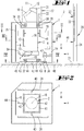
- the rotating laser shown roughly schematically, has a housing 1 which has an underside and an upper side as well as four vertical sides when the housing 1 is set up on a horizontal surface 48 by means of set-up points 43.
- the floor surface has a foot 8 which forms a fastening section with which the floor surface can also be fastened to a vertical surface.
- fastening means for example internal thread 44, can be provided with which the foot 8 or the fastening section can be fastened to a stand.
- the fastening section 8 forms a round turntable which is connected to the housing 1 via a pivot bearing 37.
- the rotary bearing 37 can be a ball bearing which has an axis of rotation 10 which is essentially a vertical axis 1 in the stationary position of the rotary laser.
- the fastening section 8 can have circumferential toothing 45, in which the teeth of a gearwheel 36 engage, which is driven in rotation by a rotary drive 47.
- the rotary drive 47 is preferably a stepper motor, so that the housing 1 can be rotated about the axis of rotation 10 in a freely selectable angular position, the fastening section 8 remaining firmly connected to the ground, for example the horizontal surface 48 or a tripod.
- a cardanic suspension for a laser beam device 2 is located inside the housing 1.
- a cardanic suspension 39 fixed to the housing supports a cardan ring body 41 which can be pivoted about a hinge axis 40.
- the joint axis 40 extends in the Y-direction running in a horizontal plane.
- the cardan ring body 41 can by means of a servomotor 6 around the Y-axis be pivoted in order to adjust the inclination of a central axis 11 of the laser beam device 2.
- the laser beam device 2 is connected to the cardan ring body 41 via joint axes 42 extending in the horizontal X direction.
- Another actuator 7 is able to pivot the laser beam device 2 about the X-axis.
- the cardanic suspensions 39 to 42 thus form an articulation point in order to align the inclined position of the laser beam device 2 or its axis 11 in such a way that it is perpendicular to a horizontal plane.
- the laser beam device 2 carries a rotary bearing 38, via which a head 17 is connected to the laser beam device 2 so that it can rotate but is axially and inclined.
- the axis of the laser beam device 2 corresponds to the axis of rotation 11, about which the head 17 can rotate with respect to the laser beam device 2.
- a rotary drive 19 is provided, which can have magnets 33 and coils 34, for example, in order to allow the head 17 to rotate around the laser beam device 2 in such a way that a laser beam 3 emerging from the head 17 at right angles to the axis of rotation 11 is in a plane of rotation perpendicular to the axis of rotation 11 rotates.
- the laser beam device 2 has a laser 15, which can be a semiconductor laser. This is fixed in place on the housing 1 and generates a laser beam 16 which is guided via an optical waveguide 64 to an emission surface 15.
- a wedge plate 32 is provided for fine adjustment of the perpendicularity of the laser beam 3 to the laser beam 16.
- Another part of the laser beam 16 passes essentially in a straight line through the pentaprism 18. Refraction effects are compensated for by a compensating prism 31 in such a way that an axial laser beam 12 propagates parallel to the axis of rotation 11 and preferably in the axis of rotation 11.
- the axial laser beam 12 is aligned in such a way that it runs as perpendicularly as possible to the plane of rotation of the rotating laser beam 3.
- first leveling means 4 which is a level which emits an electrical signal which changes when the inclination position 4 of the level is changed.
- the inclination of the laser beam device 2 about the X direction can be determined with the level 4.
- second leveling means 5 which is also formed by a spirit level, the inclination of the laser beam device 2 with respect to the Y-axis can be determined.
- a control device 9 is provided, which can be a microcontroller that sits on a printed circuit board 35.
- the control device 9 obtains information about the inclined position of the laser beam device 2 and in particular about the angular position of the axis of rotation 11 with respect to a vertical axis.
- the control device 9 is able to adjust the laser beam device 2 such that the axis of rotation 11 or the direction of the axial laser beam 12 runs in the direction of a vertical.
- the vials 4, 5 Proper calibration of the vials 4, 5 is a prerequisite.
- the vials 4, 5 can lose their calibration due to mechanical influences and / or changes in ambient parameters such as air humidity, temperature, etc.
- the housing 1 is placed on a horizontal surface 48. Then, with the incorrectly calibrated vials 4, 5, the laser beam device 2 is brought into an incorrect vertical position in which the plane of rotation of the laser beam 3 does not lie in the horizontal.
- a measuring element 20 which is a measuring receiver, which is positioned vertically at a radial distance from the housing 1, for example is set up with a foot 21 on the horizontal surface 48, the vertical position 23 of the rotating laser beam 3 is set on a measuring field 22 measured. This is the point at which the rotating laser beam 3 strikes the measuring field 22.
- the relevant value can be transmitted to the housing 1 or the control device 9 via a data transmission link 46, which can be an infrared connection.
- a first vertical position 23 is determined with a rotating laser beam 3 in the direction of the arrow ⁇ . Then, by means of the rotary drive 47, the housing is moved 180 ° in relation to the fastening section 8 into the position shown in FIG Figure 7b position shown rotated. The housing is also rotated in the direction of the arrow ⁇ . The rotating laser beam 3 now strikes at a different vertical height the measuring field 22.
- the control device 9 determines a mean value from the two vertical positions 23 and controls the servomotor 6, 7 until the laser beam 3 hits the measuring field 22 in the center.
- the housing 1 by means of the rotary drive 47 is in the Figure 7c
- the position shown, which is opposite to that in the Figures 7a and 7b shown positions is angularly offset by 90 ° with respect to the axis of rotation 11 or axis of rotation 10.
- the vertical position 23 of the plane of rotation of the laser beam 3 is now determined.
- the housing 1 is 180 ° in the Figure 7d
- the position shown is rotated and the vertical position 23 is determined again. If the two vertical positions deviate from one another, the laser beam device 2 is pivoted by means of the servomotors 6, 7 to such an extent that the plane of rotation of the laser beam 3 lies in the center of the two measured vertical positions 23.
- control device 9 sets the current values supplied by the vials 4, 5 as zero values.
- the vials 4, 5 are now calibrated.
- ambient parameter sensors determine air humidity, air pressure, temperature, etc., in order to wait before each measurement until the ambient parameters within the housing 1 have stabilized or have reached values that match the corresponding values outside of the housing 1.
- the parallelism of two machine parts 25, 26, in particular extending in a horizontal plane, and possibly other machine parts (not shown) can also be determined.
- the relevant procedure is described in Figures 5a to 6a shown roughly schematically.
- the machine parts 25, 26 can be rollers that can rotate about a horizontal axis of rotation, the aim of the measurement being to determine the offset of the axes with respect to one another.
- the housing 1 is brought into a lying position in which the axial laser beam 12 lies in a horizontal plane.
- the base plate 8 of the rotation sensor 1 can be fastened to a stand in a suitable manner, so that the axis of rotation 11 or the axis of the laser beam 12 lies approximately in a horizontal line.
- the Figures 5a, 5b show that the axial laser beam 12 is intended to extend in a Y-direction.
- the laser beam device 2 In order to bring the axial laser beam 12 into an exact horizontal position, the laser beam device 2 must be pivoted about the X-axis relative to the housing 1. This is done by means of the servomotor 6.
- a third leveling means 13 which can be a spirit level, transmits to the control device 9 the current deviation of the position of the axis of the laser beam device 2 from the horizontal.
- the third leveling means 13 is firmly connected to the laser beam device 2, but extends perpendicular to the first and second leveling means 4, 5, which are also perpendicular to one another.
- the plane of rotation of the rotating laser beam 3 lies in a vertical plane, the position of which is then determined by means of two measuring elements 20 fixedly positioned in space.
- the measuring elements 20 are fixedly positioned at a suitable point opposite the machine parts 25, 26, for example each positioned with a tripod on the machine bed or on a floor.
- the measuring elements 20 thus form stationary marking elements 27, 28 which define a reference line between them.
- the third leveling means 13, i.e. the related vial, delivers a value that depends not only on the angle of inclination ⁇ , but also on the so-called roll angle ⁇ of the housing 1 or the vial 13 with respect to the axis of rotation 11 or the axis of the axial laser beam 12.
- the roll angle ⁇ is determined in order to be stored or to set it to zero by rotating the housing 1 about the axis of rotation 10.
- a distance between the axial laser beam 12 and the machine part 25, 26 is determined at at least two measuring points 29, 30.
- the Figures 6a to 6c show the measurement of the position of the second machine part 26.
- the housing 1 is first brought into a position in which the laser beam 12 runs almost parallel to the axis of the second machine part 26.
- the position of the housing 1 is then adjusted in such a way that the laser beam 12 runs in the horizontal plane and the rotating laser beam 3 hits the measuring field 22 of the measuring elements 27, 28 used as markings.
- the tripod used for example, is set up at a different location.
- the position of the housing 1 is changed with setting elements (not shown), for example adjusting screws, until the laser beam 12 is leveled and at the same time the laser beam 3 passes through the previously determined positions of the measuring elements 20, that is to say lies in the reference line between the marking elements 27, 28.
- the roll angle ⁇ of the housing 1 or of the third leveling means 13 is also determined.
- a fourth leveling means 14, which can also be a spirit level, is used for this purpose. However, it is sufficient here if a micro-electromechanical inclination sensor is used.
- the roll angle ⁇ is set to the roll angle ⁇ which was determined when the first machine part 25 was measured.
- the axial laser beam 12 runs in the position shown in FIG. 6 exactly parallel to that in FIG Figure 5 position shown. If distance values of the axial laser beam 12 to the second machine part 26 are now determined at two different measuring points 29, 30, angular deviations of the parallelism of the two machine parts 25, 26 from one another can be calculated from the distance values obtained in the first measurement.
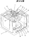
- the Figures 8 to 14 show an exemplary embodiment of a rotating laser, which is described below:
- the rotating laser has an essentially cuboid housing 1 with an underside which forms a base plate 8 with which the housing 1 can be set up on a mounting surface. For this purpose, three feet 43 protrude from the underside of the base plate 8.
- Inside the housing 1 there is a printed circuit board with an electronic circuit which forms a control device.
- a laser device 2 is also located inside the housing 1.
- the laser device 2 is gimbal-mounted around a bearing point inside the housing 1.
- This is a cardan suspension 39 is firmly connected to the housing 1.
- the cardan suspension 39 has two opposing fastening legs, from each of which a hinge axis 40 protrudes.
- a cardan ring body 41 is attached to the joint axis 40 and can be pivoted about the joint axis 40 in a horizontal direction.
- a pendulum body 51 which is part of the laser device 2, is located in an opening of the gimbal ring body 41.
- the pendulum body 51 can be pivoted relative to the cardan ring body 41 about a further hinge axis 42, which runs transversely to the hinge axis 40.
- the angle of inclination of the pendulum body 51 or the laser device 2 can be adjusted by means of two servomotors 6, 7.
- the adjusting motors are attached to the cardan ring body 41.
- the servomotor 6 is able to pivot the pendulum body 51 relative to the cardan ring body 41 about the hinge axis 42.
- the servomotor 7 With the servomotor 7, the cardan ring body 41 can be pivoted about the hinge axis 40 with respect to the cardan suspension 39 fixed to the housing.
- the servomotors 6, 7 are electric motors that act with a reduction gear on a pivot axis on which a tape or a pull tab is wound, which is connected to a projection 67, 68 of either the cardan suspension 39 or the pendulum body 51.
- the tape or pull tab is not shown in the drawings. It can be sent to a radial from that in the Figure 15 the visible axis of the servomotor 6, 7.
- the other end of the belt is attached to the projection 67 of the cardan suspension 39 or to the projection 68 of the pendulum body 51.
- the cardan suspension 39 is fixed in place on the housing 1 with suitable fastening means.
- the laser device 2 carries a head 17 which can be rotated about an axis of rotation 11, which preferably runs through the intersection of the joint axis 42 and the joint axis 40.
- a rotary drive 19 is used for this, which can bring the head 17 into a uniform rotational movement about the axis of rotation 11.
- the head 17 carries a pentaprism 18 with which a laser beam 16 running approximately coaxially to the axis of rotation 11 is deflected by 90 ° into the plane of rotation, so that a laser beam 3 rotating in a plane of rotation is produced.
- the pentaprism 18 forms a beam splitter.
- the laser beam 16 also partially emerges as an axial laser beam 12 from the head 17 of the rotary laser.
- the pendulum body 51 has a cavity in which an extension 59 of an emission surface carrier 53 is located.
- the cavity of the pendulum body 51 has an essentially circular cross section.
- the outer wall of the extension 59 is also circular in cross section and is at a radial distance from the inner wall of the cavity of the pendulum body 51.
- An end face of the pendulum body 51 pointing away from the head 17 forms a counter-contact surface 55.
- the counter-contact surface 55 runs in a plane to which the axis of rotation 11 runs perpendicular.
- the axis of rotation 11 runs approximately centrally through the cavity of the pendulum body 51.
- a contact surface 54 of the emission surface carrier 53 which is formed by a flange section of the emission surface carrier 53, is supported on the counter contact surface 55.
- the mating contact surface 55 there are several, preferably four, threaded blind bores arranged in a uniform circumferential distribution around the axis of rotation 11.
- the shaft of a fastening screw 60 is screwed into each of these threaded blind bores.
- the fastening screw 60 extends through a screw through-opening 62 of the flange section of the emission surface support 53.
- the head of the screw 60 has a covered on the direction of extent of the screw 60, the axial distance from a support surface opposite the contact surface 54, on which a spring element 61 is supported with one of its ends.
- the other end of the spring element 61 is supported on the screw head.
- the spring element which can be formed by a helical compression spring, but is formed in the exemplary embodiment by a plate spring, is pretensioned and develops a pressing force with which the contact surface 54 is pressed against the counter-contact surface 55.
- the force with which the two surfaces 54, 55 are acted upon one another generates a frictional force which must be overcome in order to move the emission surface carrier 53 transversely to the direction of extension of the axis of rotation 11 with respect to the pendulum body 51.
- the emission surface carrier 53 has the beam passage channel 52, which is provided with an exit lens 65.
- the bottom of the beam passage channel 52 has an opening 15 in its center, which has a diameter of a few micrometers. It is a diaphragm through which a laser beam 16 can exit, which enters the pentaprism 18 in the direction of the axis of rotation 11 and is divided there into the rotating laser beam 3 and the stationary axial laser beam 12.
- the laser beam is generated at a point which is arranged at a distance from the emission surface carrier 53 by means of a laser firmly connected to the housing.
- the laser beam is guided to the bottom of the beam passage channel 52 via an optical waveguide 64.
- an end section of the optical waveguide 64 is inserted into an axial plug-in opening of the emission surface carrier 53.
- the end face of the optical waveguide 64 is located directly below the opening 15, so that from the Laser light emerging from the end face of the optical waveguide 64 can exit through the aperture formed by the opening 15.
- the emission surface carrier 53 can be displaced in a direction transverse to the axis of rotation 11, the emission surface 15 can be brought from an offset position in the direction of the double arrow V into a coaxial position with respect to the axis of rotation 11.
- adjusting screws 56, 57 are provided which are opposite one another in pairs and are each offset by 90 ° with respect to the axis of rotation 11.
- the adjusting screws 56, 57 are inserted in threaded openings 58 running transversely to the axis of rotation 11.
- the position of the emission surface support 53 can be shifted in two mutually perpendicular directions relative to the pendulum body 51 or the axis of rotation 11 such that the emission surface 15 , that is to say the exit opening for the laser beam 16, can be brought into the axis of rotation 11.
- the adjustment can be carried out in the fully assembled state, since circuit boards, housing walls and / or the bottom of a battery compartment 66 form screw tool through openings 63. Screwing tool passage openings 63 are each aligned with the threaded openings 58 assigned to them, so that screwing tool passage channels are formed through which the blade of a screwdriver can be inserted from the outside of the housing in order to adjust the adjusting screws 56, 57.
Landscapes
- Physics & Mathematics (AREA)
- General Physics & Mathematics (AREA)
- Engineering & Computer Science (AREA)
- Radar, Positioning & Navigation (AREA)
- Remote Sensing (AREA)
- Manufacturing & Machinery (AREA)
- Length Measuring Devices By Optical Means (AREA)
Claims (7)
- Laser rotatif avec un boîtier, avec un dispositif à faisceau laser (2) suspendu de façon cardanique dans le boîtier, lequel génère avec une tête rotative (17) reliée fixement au dispositif laser (2) du point de vue axial et de l'inclinaison, un faisceau laser (3) tournant dans un plan de rotation (plan X/Y) autour d'un axe de rotation (11) s'étendant selon un axe Z, avec des premiers et deuxièmes moyens de nivellement (4, 5) pour déterminer une inclinaison du plan de rotation (plan X/Y) par rapport à un plan horizontal lorsque le boîtier (1) est placé sur une surface horizontale, avec un dispositif de commande (9) pour commander des servomoteurs (6, 7) d'un dispositif de réglage pour régler l'inclinaison du dispositif à faisceau laser (2) par rapport au boîtier (1) autour d'un axe X et d'un axe Y en réaction à des entrées de commande et avec une partie de montage (8) située par rapport au boîtier (1) en face de la tête (17) dans la direction de l'axe de rotation (11) et pouvant être tournée par rapport au boîtier (1) dans des positions angulaires prédéterminées au moyen d'un entraînement en rotation (47) autour d'un axe de rotation (10) qui s'étend au moins approximativement dans la même direction que l'axe de rotation (11), caractérisé par des troisièmes moyens de nivellement (13) pour déterminer un angle d'inclinaison (α) d'une inclinaison d'un faisceau laser axial (12) dirigé parallèlement à l'axe de rotation (11), par rapport au plan horizontal lorsque le boîtier (1) a été amené dans une position couchée dans laquelle l'axe de rotation (11) ou l'axe du faisceau laser (12) se situe approximativement dans un plan horizontal, le faisceau laser axial (12) pouvant être amené dans une position horizontale au moyen des servomoteurs (6) et avec des quatrièmes moyens de nivellement (14) pour déterminer un angle de roulis (β) du boîtier par rapport à l'axe de rotation (10) lorsque l'axe de rotation (11) a été amené dans une position horizontale.
- Laser rotatif selon la revendication 1, caractérisé en ce que la tête (17) comprend un pentaprisme (18) tournant autour de l'axe de rotation (11), avec lequel est généré le faisceau laser rotatif (3).
- Laser rotatif selon l'une des revendications 1 ou 2, caractérisé en ce que l'entraînement rotatif (47) agit avec une roue dentée (26) sur une denture (45) de la partie de montage (8).
- Laser rotatif selon l'une des revendications 1 à 3, caractérisé en ce qu'au moins l'un desdits premiers à quatrièmes moyens de nivellement (4, 5, 13, 14) est formé par des nivelles fixées audit dispositif à faisceau laser (2).
- Laser rotatif selon l'une des revendications 1 à 4, caractérisé par une liaison de transmission de données (46) entre un élément de mesure (20) et le dispositif de commande (9) pour transmettre une valeur de position, mesurée avec un champ de mesure (22), du point d'impact (23) du faisceau laser (3) sur le champ de mesure (22).
- Procédé pour déterminer le parallélisme de deux parties de machine (25, 26) s'étendant dans un plan horizontal avec un laser rotatif selon la revendication 1, comprenant les étapes suivantes :- placer le boîtier (1) du laser rotatif à proximité d'une première (25) des deux parties de machine (25, 26) ;- orienter le faisceau laser axial (12) dans une direction approximativement parallèle à la première partie de machine (25) ;- niveler le faisceau laser axial (12) en réglant la position du dispositif laser (2) par rapport au boîtier (1) au moyen des troisième moyens de nivellement (13) et de l'un des servomoteurs (6) du dispositif de réglage ;- détecter une ligne de référence horizontale située dans le plan de rotation du faisceau laser rotatif (3) dans l'espace au moyen d'éléments de marquage (27, 28) fixe dans l'espace ;- détecter l'angle de roulis (β) du boîtier (1) ou des troisième moyens de nivellement (13) autour de l'axe de rotation (10) par rapport au plan horizontal au moyen des quatrième moyens de nivellement (14) ;- déterminer en au moins deux points de mesure (28, 29) le long de la première partie de machine (25) la distance de celle-ci par rapport au faisceau laser axial (12) ;- déplacer le boîtier (1) du laser rotatif à proximité de la deuxième partie de machine (26) ;- aligner le plan de rotation du faisceau laser rotatif (3) dans la ligne de référence, le faisceau laser axial (12) étant nivelé et le boîtier (1) ou les troisième moyens de nivellement (13) étant amenés dans l'angle de roulis détecté (B) au moyen des quatrième moyens de nivellement (14) et de l'entraînement rotatif (47) ;- déterminer en au moins deux points de mesure (29, 30) le long de la deuxième partie de machine (26) la distance de celle-ci par rapport au faisceau laser axial (12).
- Procédé selon la revendication 6, caractérisé en ce qu'est transmise avec une liaison de transmission de données (46) entre un élément de mesure (20) formant à chaque fois un des éléments de marquage (27, 28) et un dispositif de commande (9) une valeur de position, mesurée avec un champ de mesure (22) de l'élément de mesure (20), d'un point d'impact (23) du rayon laser (3) sur le champ de mesure (22).
Applications Claiming Priority (1)
| Application Number | Priority Date | Filing Date | Title |
|---|---|---|---|
| DE102016107100.5A DE102016107100A1 (de) | 2016-04-18 | 2016-04-18 | Rotationslaser für die Vermessung von Werkzeugmaschinen |
Publications (3)
| Publication Number | Publication Date |
|---|---|
| EP3236204A2 EP3236204A2 (fr) | 2017-10-25 |
| EP3236204A3 EP3236204A3 (fr) | 2018-02-28 |
| EP3236204B1 true EP3236204B1 (fr) | 2021-07-14 |
Family
ID=58544823
Family Applications (1)
| Application Number | Title | Priority Date | Filing Date |
|---|---|---|---|
| EP17166159.8A Active EP3236204B1 (fr) | 2016-04-18 | 2017-04-12 | Laser rotatif nivelable et son utilisation dans la mesure de machines-outils |
Country Status (3)
| Country | Link |
|---|---|
| EP (1) | EP3236204B1 (fr) |
| CN (1) | CN107345795B (fr) |
| DE (1) | DE102016107100A1 (fr) |
Families Citing this family (8)
| Publication number | Priority date | Publication date | Assignee | Title |
|---|---|---|---|---|
| CN108311545B (zh) * | 2018-04-13 | 2023-10-24 | 安徽工业大学 | 一种y型轧机连轧对中及孔型检测系统及方法 |
| EP3674658A1 (fr) * | 2018-12-31 | 2020-07-01 | Hilti Aktiengesellschaft | Procédé de vérification et/ou d'étalonnage d'un axe horizontal d'un laser rotatif |
| CN111215458B (zh) * | 2019-11-12 | 2024-06-25 | 中冶京诚工程技术有限公司 | 带激光划线定位装置的轧机区生产设备及热轧生产线 |
| DE102020204536A1 (de) | 2020-04-08 | 2021-10-14 | Prüftechnik Dieter Busch GmbH | Laservorrichtung und Verfahren zum Einstellen einer Laservorrichtung |
| CN111451634A (zh) * | 2020-04-30 | 2020-07-28 | 中车青岛四方机车车辆股份有限公司 | 激光焊接设备校准方法 |
| GB202014590D0 (en) | 2020-09-16 | 2020-10-28 | Stanley Works Israel | Laser tool and system |
| CN112504218B (zh) * | 2020-12-08 | 2022-08-09 | 中国人民解放军63660部队 | 一种大口径光电经纬仪快速调平方法 |
| DE102024107594A1 (de) * | 2024-03-18 | 2025-09-18 | PM4 Innovation GmbH | Vorrichtung zum Positionieren einer optischen Ausrichthilfeeinrichtung, System, Verfahren und Einrichtung zum Ausrichten von Bauelementen |
Family Cites Families (21)
| Publication number | Priority date | Publication date | Assignee | Title |
|---|---|---|---|---|
| DE4341578C2 (de) | 1993-12-07 | 1995-11-09 | Goerlitz Waggonbau Gmbh | Rotationslaser zur Vermessung der Rechtwinkligkeit von Großbauteilen |
| JP3563457B2 (ja) * | 1994-08-30 | 2004-09-08 | 株式会社トプコン | レーザ勾配設定装置 |
| JP3357935B2 (ja) * | 1994-10-27 | 2002-12-16 | 株式会社ニコン | 距離測定装置 |
| AU5381096A (en) * | 1995-04-03 | 1996-10-23 | Momentum Laser, Inc. | Laser level |
| JP3710112B2 (ja) * | 1997-01-21 | 2005-10-26 | 株式会社トプコン | レーザ測量機 |
| JP2000180166A (ja) * | 1998-12-15 | 2000-06-30 | Asahi Optical Co Ltd | レーザ測量装置 |
| JP3908226B2 (ja) * | 2004-02-04 | 2007-04-25 | 日本電産株式会社 | スキャニング型レンジセンサ |
| CN1831476A (zh) * | 2005-03-11 | 2006-09-13 | 迈德斯托姆科技有限责任公司 | 多个激光器的激光水准仪 |
| JP4824384B2 (ja) * | 2005-10-25 | 2011-11-30 | 株式会社トプコン | レーザ測量機 |
| JP4796834B2 (ja) * | 2005-12-20 | 2011-10-19 | 株式会社トプコン | 距離測定方法及び距離測定装置 |
| DE102007055439A1 (de) * | 2007-11-21 | 2009-05-28 | Hilti Aktiengesellschaft | Rotationslaser mit Fernsteuerung |
| DE102008035480A1 (de) | 2008-07-30 | 2010-02-04 | Status Pro Maschinenmesstechnik Gmbh | Verfahren zur Vermessung von Körperoberflächen |
| EP2199739A1 (fr) * | 2008-12-17 | 2010-06-23 | Leica Geosystems AG | Récepteur laser pour la détection d'une position relative |
| DE102009001878A1 (de) * | 2009-03-26 | 2010-09-30 | Robert Bosch Gmbh | Selbstnivellierendes Mehr-Linien-Lasergerät |
| EP2522954A1 (fr) * | 2011-05-11 | 2012-11-14 | Leica Geosystems AG | Laser de construction rotatif inclinable doté d'un mécanisme de graduation et procédé pour déterminer une position d'un bras de graduation du mécanisme de graduation |
| EP2639548A1 (fr) * | 2012-03-15 | 2013-09-18 | Leica Geosystems AG | Récepteur laser capable de détecter ses propres mouvements |
| EP2781879B1 (fr) * | 2013-03-19 | 2015-09-30 | Leica Geosystems AG | Système de laser de construction constitué d'un laser rotatif et d'un récepteur laser, doté d'une fonctionnalité de détermination automatique de la direction du récepteur laser |
| EP2781880B1 (fr) * | 2013-03-19 | 2019-01-16 | Leica Geosystems AG | Système de laser de construction comportant une fonctionnalité de recalibrage s'exécutant de manière au moins partiellement automatique pour une fonctionnalité de mise à l'horizontale du rayon |
| CN104776796B (zh) * | 2014-01-13 | 2018-11-23 | 西安中科光电精密工程有限公司 | 一种用于室内空间坐标测量的光学发射器及其控制方法 |
| DE102014212797A1 (de) * | 2014-07-02 | 2016-01-07 | Prüftechnik Dieter Busch AG | Verfahren zum Ermitteln der Ausrichtung eines Laserlichtstrahls in Bezug auf eine Drehachse einer Einrichtung, die um die Drehachse rotierbar ist, und Laserlicht-Erfassungseinrichtung |
| EP3173741A1 (fr) * | 2015-11-30 | 2017-05-31 | HILTI Aktiengesellschaft | Procede de controle et/ou d'etalonnage d'un axe horizontal d'un laser rotatif |
-
2016
- 2016-04-18 DE DE102016107100.5A patent/DE102016107100A1/de active Pending
-
2017
- 2017-04-12 EP EP17166159.8A patent/EP3236204B1/fr active Active
- 2017-04-13 CN CN201710239122.XA patent/CN107345795B/zh active Active
Non-Patent Citations (1)
| Title |
|---|
| None * |
Also Published As
| Publication number | Publication date |
|---|---|
| EP3236204A3 (fr) | 2018-02-28 |
| EP3236204A2 (fr) | 2017-10-25 |
| CN107345795A (zh) | 2017-11-14 |
| DE102016107100A1 (de) | 2017-10-19 |
| CN107345795B (zh) | 2020-09-22 |
Similar Documents
| Publication | Publication Date | Title |
|---|---|---|
| EP3236204B1 (fr) | Laser rotatif nivelable et son utilisation dans la mesure de machines-outils | |
| EP3384239B1 (fr) | Procede de controle et/ou d'etalonnage d'un axe horizontal d'un laser rotatif | |
| EP3384236B1 (fr) | Procédé de contrôle et/ou d'étalonnage d'un axe vertical d'un laser rotatif | |
| EP3384238B1 (fr) | Procede de controle d'un laser rotatif afin de detecter une erreur de cone | |
| EP3906390B1 (fr) | Procédé de vérification et/ou d'étalonnage d'un axe horizontal d'un laser rotatif | |
| EP3173740A1 (fr) | Procédé télémétrique entre un laser rotatif et un récepteur laser | |
| EP2455711A2 (fr) | Appareil à laser rotatif doté d'un plan de laser incliné et procédé d'alignement d'un appareil à laser rotatif | |
| EP1110439B1 (fr) | Procede et dispositif pour etalonner un deplacement et/ou une position angulaire d'un systeme de retenue dans un dispositif destine a produire des blocs de composants electriques et substrat d'etalonnage | |
| EP3028063B1 (fr) | Procédé pour calibrer un appareil de mesure | |
| DE102015226387B4 (de) | Verfahren zur Durchführung von Messungen mit einem Prüfelement in einem Koordinatenmessgerät oder einer Werkzeugmaschine | |
| EP3176606B1 (fr) | Procédé destiné à l'alignement d'un scanner laser | |
| DE19748239A1 (de) | Verfahren und Vorrichtung zur berührungslosen Bestimmung von Sturz und Vorlauf eines Fahrzeugrads | |
| EP1342051A1 (fr) | Calibrage d'un capteur d'un appareil de mesure de coordonnees au moyen d'une boule et de deux champs de parametres | |
| WO2008071251A2 (fr) | Dispositif pour détecter des mouvements et des forces | |
| EP3236205B1 (fr) | Laser rotatif | |
| WO2018115071A1 (fr) | Dispositif destiné à être utilisé dans une machine-outil à commande numérique conçue pour être employée dans un procédé pour mesurer la machine-outil à commande numérique | |
| EP3384237A1 (fr) | Procédé d'orientation d'un axe d'appareil dans un état défini | |
| EP0419916B1 (fr) | Dispositif pour examiner le parallélisme de deux axes | |
| EP3384233A1 (fr) | Procédé de mesure d'une température de fonctionnement d'un appareil | |
| DE102020103008A1 (de) | Leiterplatte | |
| EP2026373B1 (fr) | Dispositif de positionnement destiné au positionnement d'un diaphragme dans un rayon d'ions | |
| EP0881462B1 (fr) | Dispositif pour mesurer la largeur des marches d'escalier | |
| DE202012005599U1 (de) | Digitale Pitchlehre | |
| WO2003012548A2 (fr) | Systeme permettant le calibrage d'un systeme optique, notamment d'un objectif | |
| DE102020204536A1 (de) | Laservorrichtung und Verfahren zum Einstellen einer Laservorrichtung |
Legal Events
| Date | Code | Title | Description |
|---|---|---|---|
| PUAI | Public reference made under article 153(3) epc to a published international application that has entered the european phase |
Free format text: ORIGINAL CODE: 0009012 |
|
| STAA | Information on the status of an ep patent application or granted ep patent |
Free format text: STATUS: THE APPLICATION HAS BEEN PUBLISHED |
|
| AK | Designated contracting states |
Kind code of ref document: A2 Designated state(s): AL AT BE BG CH CY CZ DE DK EE ES FI FR GB GR HR HU IE IS IT LI LT LU LV MC MK MT NL NO PL PT RO RS SE SI SK SM TR |
|
| AX | Request for extension of the european patent |
Extension state: BA ME |
|
| PUAL | Search report despatched |
Free format text: ORIGINAL CODE: 0009013 |
|
| AK | Designated contracting states |
Kind code of ref document: A3 Designated state(s): AL AT BE BG CH CY CZ DE DK EE ES FI FR GB GR HR HU IE IS IT LI LT LU LV MC MK MT NL NO PL PT RO RS SE SI SK SM TR |
|
| AX | Request for extension of the european patent |
Extension state: BA ME |
|
| RIC1 | Information provided on ipc code assigned before grant |
Ipc: G01C 25/00 20060101ALI20180124BHEP Ipc: G01C 15/00 20060101AFI20180124BHEP Ipc: G01B 11/27 20060101ALI20180124BHEP |
|
| STAA | Information on the status of an ep patent application or granted ep patent |
Free format text: STATUS: REQUEST FOR EXAMINATION WAS MADE |
|
| 17P | Request for examination filed |
Effective date: 20180803 |
|
| RBV | Designated contracting states (corrected) |
Designated state(s): AL AT BE BG CH CY CZ DE DK EE ES FI FR GB GR HR HU IE IS IT LI LT LU LV MC MK MT NL NO PL PT RO RS SE SI SK SM TR |
|
| STAA | Information on the status of an ep patent application or granted ep patent |
Free format text: STATUS: EXAMINATION IS IN PROGRESS |
|
| 17Q | First examination report despatched |
Effective date: 20191121 |
|
| GRAP | Despatch of communication of intention to grant a patent |
Free format text: ORIGINAL CODE: EPIDOSNIGR1 |
|
| STAA | Information on the status of an ep patent application or granted ep patent |
Free format text: STATUS: GRANT OF PATENT IS INTENDED |
|
| INTG | Intention to grant announced |
Effective date: 20210210 |
|
| RIN1 | Information on inventor provided before grant (corrected) |
Inventor name: FOLEY, DAVID Inventor name: KNODE, BURKHARD |
|
| GRAS | Grant fee paid |
Free format text: ORIGINAL CODE: EPIDOSNIGR3 |
|
| GRAA | (expected) grant |
Free format text: ORIGINAL CODE: 0009210 |
|
| STAA | Information on the status of an ep patent application or granted ep patent |
Free format text: STATUS: THE PATENT HAS BEEN GRANTED |
|
| AK | Designated contracting states |
Kind code of ref document: B1 Designated state(s): AL AT BE BG CH CY CZ DE DK EE ES FI FR GB GR HR HU IE IS IT LI LT LU LV MC MK MT NL NO PL PT RO RS SE SI SK SM TR |
|
| REG | Reference to a national code |
Ref country code: GB Ref legal event code: FG4D Free format text: NOT ENGLISH |
|
| REG | Reference to a national code |
Ref country code: DE Ref legal event code: R096 Ref document number: 502017010881 Country of ref document: DE |
|
| REG | Reference to a national code |
Ref country code: IE Ref legal event code: FG4D Free format text: LANGUAGE OF EP DOCUMENT: GERMAN |
|
| REG | Reference to a national code |
Ref country code: AT Ref legal event code: REF Ref document number: 1411001 Country of ref document: AT Kind code of ref document: T Effective date: 20210815 |
|
| REG | Reference to a national code |
Ref country code: LT Ref legal event code: MG9D |
|
| REG | Reference to a national code |
Ref country code: NL Ref legal event code: MP Effective date: 20210714 |
|
| PG25 | Lapsed in a contracting state [announced via postgrant information from national office to epo] |
Ref country code: HR Free format text: LAPSE BECAUSE OF FAILURE TO SUBMIT A TRANSLATION OF THE DESCRIPTION OR TO PAY THE FEE WITHIN THE PRESCRIBED TIME-LIMIT Effective date: 20210714 Ref country code: FI Free format text: LAPSE BECAUSE OF FAILURE TO SUBMIT A TRANSLATION OF THE DESCRIPTION OR TO PAY THE FEE WITHIN THE PRESCRIBED TIME-LIMIT Effective date: 20210714 Ref country code: ES Free format text: LAPSE BECAUSE OF FAILURE TO SUBMIT A TRANSLATION OF THE DESCRIPTION OR TO PAY THE FEE WITHIN THE PRESCRIBED TIME-LIMIT Effective date: 20210714 Ref country code: NL Free format text: LAPSE BECAUSE OF FAILURE TO SUBMIT A TRANSLATION OF THE DESCRIPTION OR TO PAY THE FEE WITHIN THE PRESCRIBED TIME-LIMIT Effective date: 20210714 Ref country code: PT Free format text: LAPSE BECAUSE OF FAILURE TO SUBMIT A TRANSLATION OF THE DESCRIPTION OR TO PAY THE FEE WITHIN THE PRESCRIBED TIME-LIMIT Effective date: 20211115 Ref country code: NO Free format text: LAPSE BECAUSE OF FAILURE TO SUBMIT A TRANSLATION OF THE DESCRIPTION OR TO PAY THE FEE WITHIN THE PRESCRIBED TIME-LIMIT Effective date: 20211014 Ref country code: LT Free format text: LAPSE BECAUSE OF FAILURE TO SUBMIT A TRANSLATION OF THE DESCRIPTION OR TO PAY THE FEE WITHIN THE PRESCRIBED TIME-LIMIT Effective date: 20210714 Ref country code: BG Free format text: LAPSE BECAUSE OF FAILURE TO SUBMIT A TRANSLATION OF THE DESCRIPTION OR TO PAY THE FEE WITHIN THE PRESCRIBED TIME-LIMIT Effective date: 20211014 Ref country code: SE Free format text: LAPSE BECAUSE OF FAILURE TO SUBMIT A TRANSLATION OF THE DESCRIPTION OR TO PAY THE FEE WITHIN THE PRESCRIBED TIME-LIMIT Effective date: 20210714 Ref country code: RS Free format text: LAPSE BECAUSE OF FAILURE TO SUBMIT A TRANSLATION OF THE DESCRIPTION OR TO PAY THE FEE WITHIN THE PRESCRIBED TIME-LIMIT Effective date: 20210714 |
|
| PG25 | Lapsed in a contracting state [announced via postgrant information from national office to epo] |
Ref country code: PL Free format text: LAPSE BECAUSE OF FAILURE TO SUBMIT A TRANSLATION OF THE DESCRIPTION OR TO PAY THE FEE WITHIN THE PRESCRIBED TIME-LIMIT Effective date: 20210714 Ref country code: LV Free format text: LAPSE BECAUSE OF FAILURE TO SUBMIT A TRANSLATION OF THE DESCRIPTION OR TO PAY THE FEE WITHIN THE PRESCRIBED TIME-LIMIT Effective date: 20210714 Ref country code: GR Free format text: LAPSE BECAUSE OF FAILURE TO SUBMIT A TRANSLATION OF THE DESCRIPTION OR TO PAY THE FEE WITHIN THE PRESCRIBED TIME-LIMIT Effective date: 20211015 |
|
| REG | Reference to a national code |
Ref country code: DE Ref legal event code: R097 Ref document number: 502017010881 Country of ref document: DE |
|
| PG25 | Lapsed in a contracting state [announced via postgrant information from national office to epo] |
Ref country code: DK Free format text: LAPSE BECAUSE OF FAILURE TO SUBMIT A TRANSLATION OF THE DESCRIPTION OR TO PAY THE FEE WITHIN THE PRESCRIBED TIME-LIMIT Effective date: 20210714 |
|
| PLBE | No opposition filed within time limit |
Free format text: ORIGINAL CODE: 0009261 |
|
| STAA | Information on the status of an ep patent application or granted ep patent |
Free format text: STATUS: NO OPPOSITION FILED WITHIN TIME LIMIT |
|
| PG25 | Lapsed in a contracting state [announced via postgrant information from national office to epo] |
Ref country code: SM Free format text: LAPSE BECAUSE OF FAILURE TO SUBMIT A TRANSLATION OF THE DESCRIPTION OR TO PAY THE FEE WITHIN THE PRESCRIBED TIME-LIMIT Effective date: 20210714 Ref country code: SK Free format text: LAPSE BECAUSE OF FAILURE TO SUBMIT A TRANSLATION OF THE DESCRIPTION OR TO PAY THE FEE WITHIN THE PRESCRIBED TIME-LIMIT Effective date: 20210714 Ref country code: RO Free format text: LAPSE BECAUSE OF FAILURE TO SUBMIT A TRANSLATION OF THE DESCRIPTION OR TO PAY THE FEE WITHIN THE PRESCRIBED TIME-LIMIT Effective date: 20210714 Ref country code: EE Free format text: LAPSE BECAUSE OF FAILURE TO SUBMIT A TRANSLATION OF THE DESCRIPTION OR TO PAY THE FEE WITHIN THE PRESCRIBED TIME-LIMIT Effective date: 20210714 Ref country code: CZ Free format text: LAPSE BECAUSE OF FAILURE TO SUBMIT A TRANSLATION OF THE DESCRIPTION OR TO PAY THE FEE WITHIN THE PRESCRIBED TIME-LIMIT Effective date: 20210714 Ref country code: AL Free format text: LAPSE BECAUSE OF FAILURE TO SUBMIT A TRANSLATION OF THE DESCRIPTION OR TO PAY THE FEE WITHIN THE PRESCRIBED TIME-LIMIT Effective date: 20210714 |
|
| 26N | No opposition filed |
Effective date: 20220419 |
|
| PG25 | Lapsed in a contracting state [announced via postgrant information from national office to epo] |
Ref country code: IT Free format text: LAPSE BECAUSE OF FAILURE TO SUBMIT A TRANSLATION OF THE DESCRIPTION OR TO PAY THE FEE WITHIN THE PRESCRIBED TIME-LIMIT Effective date: 20210714 |
|
| REG | Reference to a national code |
Ref country code: CH Ref legal event code: PL |
|
| GBPC | Gb: european patent ceased through non-payment of renewal fee |
Effective date: 20220412 |
|
| REG | Reference to a national code |
Ref country code: BE Ref legal event code: MM Effective date: 20220430 |
|
| PG25 | Lapsed in a contracting state [announced via postgrant information from national office to epo] |
Ref country code: MC Free format text: LAPSE BECAUSE OF FAILURE TO SUBMIT A TRANSLATION OF THE DESCRIPTION OR TO PAY THE FEE WITHIN THE PRESCRIBED TIME-LIMIT Effective date: 20210714 Ref country code: LU Free format text: LAPSE BECAUSE OF NON-PAYMENT OF DUE FEES Effective date: 20220412 Ref country code: LI Free format text: LAPSE BECAUSE OF NON-PAYMENT OF DUE FEES Effective date: 20220430 Ref country code: GB Free format text: LAPSE BECAUSE OF NON-PAYMENT OF DUE FEES Effective date: 20220412 Ref country code: FR Free format text: LAPSE BECAUSE OF NON-PAYMENT OF DUE FEES Effective date: 20220430 Ref country code: CH Free format text: LAPSE BECAUSE OF NON-PAYMENT OF DUE FEES Effective date: 20220430 |
|
| PG25 | Lapsed in a contracting state [announced via postgrant information from national office to epo] |
Ref country code: BE Free format text: LAPSE BECAUSE OF NON-PAYMENT OF DUE FEES Effective date: 20220430 |
|
| PG25 | Lapsed in a contracting state [announced via postgrant information from national office to epo] |
Ref country code: IE Free format text: LAPSE BECAUSE OF NON-PAYMENT OF DUE FEES Effective date: 20220412 |
|
| REG | Reference to a national code |
Ref country code: AT Ref legal event code: MM01 Ref document number: 1411001 Country of ref document: AT Kind code of ref document: T Effective date: 20220412 |
|
| P01 | Opt-out of the competence of the unified patent court (upc) registered |
Effective date: 20230512 |
|
| PG25 | Lapsed in a contracting state [announced via postgrant information from national office to epo] |
Ref country code: AT Free format text: LAPSE BECAUSE OF NON-PAYMENT OF DUE FEES Effective date: 20220412 |
|
| PG25 | Lapsed in a contracting state [announced via postgrant information from national office to epo] |
Ref country code: HU Free format text: LAPSE BECAUSE OF FAILURE TO SUBMIT A TRANSLATION OF THE DESCRIPTION OR TO PAY THE FEE WITHIN THE PRESCRIBED TIME-LIMIT; INVALID AB INITIO Effective date: 20170412 |
|
| PG25 | Lapsed in a contracting state [announced via postgrant information from national office to epo] |
Ref country code: MK Free format text: LAPSE BECAUSE OF FAILURE TO SUBMIT A TRANSLATION OF THE DESCRIPTION OR TO PAY THE FEE WITHIN THE PRESCRIBED TIME-LIMIT Effective date: 20210714 Ref country code: CY Free format text: LAPSE BECAUSE OF FAILURE TO SUBMIT A TRANSLATION OF THE DESCRIPTION OR TO PAY THE FEE WITHIN THE PRESCRIBED TIME-LIMIT Effective date: 20210714 |
|
| PG25 | Lapsed in a contracting state [announced via postgrant information from national office to epo] |
Ref country code: MT Free format text: LAPSE BECAUSE OF FAILURE TO SUBMIT A TRANSLATION OF THE DESCRIPTION OR TO PAY THE FEE WITHIN THE PRESCRIBED TIME-LIMIT Effective date: 20210714 |
|
| PGFP | Annual fee paid to national office [announced via postgrant information from national office to epo] |
Ref country code: DE Payment date: 20250416 Year of fee payment: 9 |
|
| PG25 | Lapsed in a contracting state [announced via postgrant information from national office to epo] |
Ref country code: TR Free format text: LAPSE BECAUSE OF FAILURE TO SUBMIT A TRANSLATION OF THE DESCRIPTION OR TO PAY THE FEE WITHIN THE PRESCRIBED TIME-LIMIT Effective date: 20210714 |