EP3236455A1 - Drucksache - Google Patents
Drucksache Download PDFInfo
- Publication number
- EP3236455A1 EP3236455A1 EP15869961.1A EP15869961A EP3236455A1 EP 3236455 A1 EP3236455 A1 EP 3236455A1 EP 15869961 A EP15869961 A EP 15869961A EP 3236455 A1 EP3236455 A1 EP 3236455A1
- Authority
- EP
- European Patent Office
- Prior art keywords
- layer
- light
- printed matter
- adjustment layer
- light adjustment
- Prior art date
- Legal status (The legal status is an assumption and is not a legal conclusion. Google has not performed a legal analysis and makes no representation as to the accuracy of the status listed.)
- Withdrawn
Links
Images


Classifications
-
- G—PHYSICS
- G09—EDUCATION; CRYPTOGRAPHY; DISPLAY; ADVERTISING; SEALS
- G09F—DISPLAYING; ADVERTISING; SIGNS; LABELS OR NAME-PLATES; SEALS
- G09F13/00—Illuminated signs; Luminous advertising
- G09F13/04—Signs, boards or panels, illuminated from behind the insignia
-
- B—PERFORMING OPERATIONS; TRANSPORTING
- B41—PRINTING; LINING MACHINES; TYPEWRITERS; STAMPS
- B41M—PRINTING, DUPLICATING, MARKING, OR COPYING PROCESSES; COLOUR PRINTING
- B41M5/00—Duplicating or marking methods; Sheet materials for use therein
- B41M5/50—Recording sheets characterised by the coating used to improve ink, dye or pigment receptivity, e.g. for ink-jet or thermal dye transfer recording
- B41M5/502—Recording sheets characterised by the coating used to improve ink, dye or pigment receptivity, e.g. for ink-jet or thermal dye transfer recording characterised by structural details, e.g. multilayer materials
-
- B—PERFORMING OPERATIONS; TRANSPORTING
- B44—DECORATIVE ARTS
- B44F—SPECIAL DESIGNS OR PICTURES
- B44F1/00—Designs or pictures characterised by special or unusual light effects
- B44F1/02—Designs or pictures characterised by special or unusual light effects produced by reflected light, e.g. matt surfaces, lustrous surfaces
- B44F1/04—Designs or pictures characterised by special or unusual light effects produced by reflected light, e.g. matt surfaces, lustrous surfaces after passage through surface layers, e.g. pictures with mirrors on the back
-
- B—PERFORMING OPERATIONS; TRANSPORTING
- B44—DECORATIVE ARTS
- B44F—SPECIAL DESIGNS OR PICTURES
- B44F1/00—Designs or pictures characterised by special or unusual light effects
- B44F1/06—Designs or pictures characterised by special or unusual light effects produced by transmitted light, e.g. transparencies, imitations of glass paintings
-
- B—PERFORMING OPERATIONS; TRANSPORTING
- B44—DECORATIVE ARTS
- B44F—SPECIAL DESIGNS OR PICTURES
- B44F7/00—Designs imitating three-dimensional [3D] effects
-
- G—PHYSICS
- G09—EDUCATION; CRYPTOGRAPHY; DISPLAY; ADVERTISING; SEALS
- G09F—DISPLAYING; ADVERTISING; SIGNS; LABELS OR NAME-PLATES; SEALS
- G09F13/00—Illuminated signs; Luminous advertising
- G09F13/16—Signs formed of or incorporating reflecting elements or surfaces, e.g. warning signs having triangular or other geometrical shape
-
- B—PERFORMING OPERATIONS; TRANSPORTING
- B41—PRINTING; LINING MACHINES; TYPEWRITERS; STAMPS
- B41M—PRINTING, DUPLICATING, MARKING, OR COPYING PROCESSES; COLOUR PRINTING
- B41M3/00—Printing processes to produce particular kinds of printed work, e.g. patterns
- B41M3/06—Veined printings; Fluorescent printings; Stereoscopic images; Imitated patterns, e.g. tissues, textiles
-
- G—PHYSICS
- G09—EDUCATION; CRYPTOGRAPHY; DISPLAY; ADVERTISING; SEALS
- G09F—DISPLAYING; ADVERTISING; SIGNS; LABELS OR NAME-PLATES; SEALS
- G09F13/00—Illuminated signs; Luminous advertising
- G09F13/04—Signs, boards or panels, illuminated from behind the insignia
- G09F13/0418—Constructional details
- G09F13/0422—Reflectors
Definitions
- the present invention relates to printed matter, and in particular to techniques related to improvement of image quality in stereoscopic printing.
- Patent Literature 1 to 5 Various types of printed matter have been developed that allow printed images to be perceived stereoscopically.
- Example include printed matter in which a lenticular lens is formed on an image printed on a medium (Patent Literature 1), and printed matter in which surface irregularities are formed by a clear layer made of a light-transmissive resin, and images formed above or below the resin are perceived to be stereoscopic (Patent Literature 2, 3).
- Print matter has also been developed in which in addition to light irradiating a front side of the printed matter, reflected light causing a viewer to perceive an image, light is made incident on a back side of the medium, transmitted light causing a viewer to perceive an image.
- the present invention has been made to solve such a problem, and it is an object of the present invention to provide printed matter that can achieve high image quality in both a case of perception of an image via transmitted light and a case of perception of an image via reflected light.
- Printed matter pertaining to one aspect of the present invention includes a substrate, a laminated clear layer, and a light adjustment layer.
- the substrate is light-transmissive.
- the laminated clear layer is disposed above a main surface (single main surface) of the substrate, and is composed of clear element layers that are light-transmissive.
- the light adjustment layer has a function of adjusting an amount of light transmitted therethrough and is disposed on the laminated clear layer and/or interposed between a plurality of the clear element layers.
- the light adjustment layer includes light reflective particles and covers a portion of a surface thereunder.
- Each of the light reflective particles is granular and has a light reflective surface.
- the light adjustment layer in terms of surface area ratio in plan view, covers from 2 % to 50 % of the surface of the layer thereunder.
- Printed matter pertaining to one aspect of the present invention includes a substrate, a laminated clear layer, and a light adjustment layer.
- the substrate is light-transmissive.
- the laminated clear layer is disposed above a main surface (single main surface) of the substrate, and is composed of clear element layers that are light-transmissive. Note that in the present description, "disposed above” includes both a case in which a layer is disposed directly on an underlying layer and a case in which the layer is disposed above the underlying layer with another layer interposed therebetween.
- the light adjustment layer has a function of adjusting an amount of light transmitted therethrough and is disposed on the laminated clear layer and/or interposed between a plurality of the clear element layers.
- the light adjustment layer includes light reflective particles and covers a portion of a surface thereunder.
- Each of the light reflective particles is granular and has a light reflective surface.
- the light adjustment layer in terms of surface area ratio in plan view, covers from 2 % to 50 % of the surface of the layer thereunder.
- the light adjustment layer covers from 2 % to 50 % of surface area ratio of a surface of an underlying layer (corresponding to "density from 2 % to 50 %), and therefore it is possible to realize a high image quality both when an image is perceived via transmitted light and when an image is perceived via reflected light.
- the light adjustment layer is provided in a dot pattern. According to this configuration it is possible to realize a high image quality both in a case in which an image is perceived via transmitted light and in a case in which an image is perceived via reflected light.
- dot pattern means a layer formed from a pattern (dot pattern) of small dots printed on a surface of an underlying layer, and includes cases in which adjacent dots are connected to each other.
- Another example of the printed matter pertaining to an aspect of the present invention further comprises a color layer.
- the color layer is disposed above the main surface of the substrate, extending in a direction along the main surface of the substrate, and including one color or a plurality of colors.
- a viewer can perceive a vividly expressed image. Further, by providing the light adjustment layer, excellent color reproduction can be realized, in particular when perceiving an image via transmitted light.
- the color layer is disposed covering a top surface of the laminated clear layer
- the light adjustment layer is disposed covering a top surface of the color layer and side surfaces of the laminated clear layer and the color layer.
- the first aspect it is also possible to reproduce an image with transparency by adding a clear layer having a thin thickness on the light adjustment layer.
- second aspect further comprises a second light adjustment layer.
- the second light adjustment layer has a function of adjusting an amount of light transmitted therethrough, and is interposed between the main surface of the substrate and the laminated clear layer.
- the second light adjustment layer includes light reflective particles that are granular and each have a light reflective surface.
- the second light adjustment layer in terms of surface area ratio in plan view, covers from 2 % to 50 % of a surface of a layer thereunder.
- a reflective layer (white layer) can be formed at a density of 100 %, for example.
- the second light adjustment layer when the second light adjustment layer is disposed between a main surface of the substrate and the laminated clear layer and a viewer perceives an image via reflected light, a portion of light that is incident from above is reflected at the second light adjustment layer. Thus, a ratio of the amount of reflected light to light incident from above can be increased.
- the printed matter pertaining to the second aspect it is possible to further improve image quality both in a case in which an image is perceived via transmitted light and in a case in which an image is perceived via reflected light.
- the surface area ratio (density) of coverage by the second light adjustment layer is greater than the surface area ratio (density) of coverage by the light adjustment layer.
- the light adjustment layer is disposed covering a top surface and side surfaces of the laminated clear layer, and the color layer is disposed covering a top surface of the light adjustment layer.
- the light adjustment layer covers the laminated clear layer and is disposed below the color layer, when a viewer perceives an image via light that is incident on a back surface of the substrate and transmitted, it is possible to suppress effects on color tone caused by irregular reflection of light at the laminated clear layer. Irregular reflection of transmitted light in the laminated clear layer is thought to be caused, for example, by surface irregularity of an upper side or lower side of each clear element layer.
- the color layer is a layered body composed of a plurality of color element layers.
- texture of an image can be enhanced.
- the printed matter pertaining to an aspect of the present invention further comprises a protective layer.
- the protective layer is light transmissive and disposed covering a top surface of a top layer thereunder (the protective layer is disposed as the topmost surface of the printed matter).
- the protective layer is disposed as the topmost surface of a layered structure
- the protective layer is subjected to a matt treatment.
- this can be implemented by forming an irregular surface.
- texture of an image can be changed between a treated and untreated region.
- a region of an image that represents a glossy metal surface or the like is not subjecting to matt treatment and is set to be glossy, and a region of the image that represents a rough surface is subjected to matt treatment.
- Another example of printed matter pertaining to an aspect of the present invention further comprises a second laminated clear layer disposed above the laminated clear layer and the light adjustment layer, composed of clear element layers that are light transmissive. According to disposition of the second light laminated clear layer in this way, it is possible to further enhance color tone of an image.
- color of a deep color portion of the color layer can be further emphasized and a higher degree of texture can be realized.
- the surface area ratio (density) of coverage by the light adjustment layer is from 20 % to 30 %. According to this density range, it is possible to ensure higher print quality in both a case in which a viewer perceives an image via transmitted light and a case in which a viewer perceives an image via reflected light.
- the light reflective particles of the light adjustment layer are made of white pigment. According to such a configuration, for example, it is possible to form the light adjustment layer by dropping ultraviolet (UV) curable ink by using an inkjet device, allowing easy production. As described above, it is also possible to preliminarily apply a primer to a surface of an underlying layer in consideration of ink affinity of the underlying layer.
- UV ultraviolet
- thickness of the light adjustment layer is from 0.010 mm to 0.030 mm.
- the substrate is made of resin or glass.
- the illumination device 1 is configured to have a backlight 20 and printed matter 10.
- the illumination device 1 includes other elements such as driver circuitry, but these are not illustrated.
- a pseudo embossing process (ink embossing process) is applied to a main face (front face) of the printed matter 10.
- the backlight 20 includes an LED 21 as a light source, disposed facing an end face of a light guide plate 22 (edge light system).
- the printed matter 10 is disposed in close contact with a Z axis direction top face of the light guide plate 22.
- a Z axis direction bottom face and an end face not facing the LED 21 of the light guide plate 22 are covered by a reflection plate 23.
- FIG. 2 is a schematic cross section enlargement of portion A in FIG. 1 .
- a light diffusion plate 100 is formed as a base substrate and one main surface (front surface) 10a thereof is subjected to ink embossing treatment.
- a back surface 10b is disposed in close contact with the light guide plate 22 (see FIG. 1 ).
- the light diffusion plate 100 is made of an acrylic resin and matting of a surface thereof imparts a light diffusing function thereto.
- Convex portions 10d 1 , 10d 2 are formed on the Z axis top surface of the light diffusing plate 100, and spaces between adjacent ones of the convex portions 10d 1 , 10d 2 ... form concave portions 10c ....
- clear element layers 102, 103, 104, and 105 are layered on the light diffusion plate 100.
- a laminated body of the clear element layers 102-105 is referred to as a laminated clear layer 101.
- a color layer 106 is layered so as to cover a top surface and side surfaces of the laminated clear layer 101.
- the color layer 106 is schematically shown, but in detail the color layer 106 is formed by full color printing using four colors of ink: cyan (C), magenta (M), yellow (Y), and black (K). UV-curable ink is used, and the ink is applied by using an inkjet device.
- a light adjustment layer 107 is formed so as to cover a top surface of the color layer 106.
- the light adjustment layer 107 is formed so as to also cover a surface of the light diffusion plate 100 in the concave portion 10c.
- the light adjustment layer 107 is formed in a dot pattern by using UV curable ink and an inkjet device is for ink application.
- a primer may be pre-applied on a surface of an underlying layer in consideration of ink affinity of the underlying layer.
- light L 1 is transmitted from the back surface 10b to the front surface 10a when the LED 21 is lit, and light L 2 incident from the front surface 10a is reflected to be emitted towards an observer when the LED 21 is not lit.
- the clear element layers 102-105 each have a trapezoidal shape in cross section, and are layered in a pyramid from a Z axis direction lower side.
- cross section shape of each layer is not limited to this example, and a portion of layers may have the same cross section size as layers above and below, or all layers may have the same cross section size.
- the color layer 106 can also be formed on a side surface of the laminated clear layer 101, and an image formed all over an entire region visible to a viewer.
- each layer by rounding upper corners of each layer, it is possible to improve image quality as perceived by a viewer.
- FIG. 3A shows a case of the present embodiment
- FIG. 3B and FIG. 3C show cases of comparative examples.
- the light adjustment layer 107 has a function of shielding a portion of light transmitted therethrough, while another portion of light is transmitted therethrough.
- the light adjustment layer 107 pertaining to the present embodiment is formed in dot pattern and functions to balance amounts of transmitted and reflected light. More specific configuration is described later.
- the laminated clear layer 101 is formed in order to form the convex portions 10d1, 10d2, but particularly for transmitted light, light for which yellow coloring occurs tends to be emitted.
- the light adjustment layer 107 is formed on the color layer 106, and therefore yellow coloring caused by the laminated clear layer 101 can be suppressed, and even when an image is perceived by transmitted light, emitted light L 3 that is transmitted through the color layer 106 exhibits excellent color reproduction. In particular, when the color layer 106 is primarily a pale color, excellent color reproduction is exhibited.
- printed matter 90 is assumed to have a configuration in which a laminated clear layer 901 and a color layer 906 are layered in this order on a substrate 900 and a light adjustment layer is not provided above the color layer 906 in the Z axis direction.
- a light adjustment layer is not provided above the color layer 906 in the Z axis direction.
- color tone of an image perceived by an observer is different between transmitted light and reflected light.
- image quality is reduced, particularly when an image is perceived by a viewer via transmitted light.
- printed matter 91 is assumed to use a medium such as paper as a substrate 910, on which a white reflective layer 917, a laminated clear layer 911, and a color layer 916 are formed in this order.
- Light L 5 incident on the printed matter 91, configured as above, from above in the Z axis direction is mostly reflected by the white reflective layer 917, is transmitted through the color layer 916, and emitted from a front surface 91a (light L 6 ).
- Perception of an image by transmitted light is not intended for comparative example 2, and therefore a function of the white reflective layer 917 is to reflect as much as possible of light L 5 that is incident from above.
- the white reflective layer 917 provided for the purpose of light reflection reflects not only light from above in the Z axis direction, but also light from below in the Z axis direction.
- Layer thicknesses of each layer are described with reference to FIG. 4A as an example of the present embodiment.
- a total thickness t CA of the laminated clear layer 101 is approximately 0.08 mm.
- a layer thickness t C1 of each of the clear element layers 102-105 that constitute the laminated clear layer 101 is approximately 0.02 mm.
- the laminated clear layer 101 is a layered body comprising the four layers of the clear element layers 102-105, but the number of layers can be changed according to an image to be expressed. Further, thicknesses of the clear element layers need not be the same as each other, and may be different from each other.
- a thickness t VL of the light adjustment layer 107 formed on the color layer 106 is from 0.010 mm to 0.030 mm, or more preferably from 0.010 mm to 0.020 mm (for example, 0.020 mm).
- the layer thickness t VL of the light adjustment layer 107 can be appropriately determined in view of such factors as an amount of transmitted light and thickness of the laminated clear layer.
- the light adjustment layer 107 pertaining to the present embodiment is formed in a dot pattern on a surface of the color layer 106 thereunder.
- the light adjustment layer 107 includes white pigment.
- the light adjustment layer 107 is considered to contain a resin component in addition to the white particles, and is bonded to a surface of the color layer 106 by the resin component.
- the resin component materials such as an epoxy resin material, a urethane resin material, a polyester resin material, or the like can be used.
- white particles are not aggregated and are in a dispersed state.
- the light adjustment layer 107 is formed to cover a portion of a surface of the color layer 106 (formed in a dot pattern), and is adjusted to cover a surface area ratio from 2 % to 50 % of the surface of the color layer 106.
- the surface area ratio covered by the light adjustment layer 107 is more preferably from 20 % to 30 % of the surface of the color layer 106.
- the surface area ratio is 30 %.
- a pattern is formed on side walls 800, 801 disposed either side of a passage 80. Further, a plurality of the illumination device 1 is embedded in lower portions of the side walls 800, 801. Each of the illumination devices 1 has a configuration as described above, and when the LED 21 is lit, emits light L 3 .
- patterning (image and convexity/concavity) of the illumination devices 1 is substantially the same as patterning (image and convexity/concavity) of the side walls 800, 801 other than the illumination devices 1. That is, regardless of whether the LED 21 is lit or not, a person passing through the passage 80 can feel as if portions of the side walls 800, 801 are glowing, and when the LED 21 is not lit, it is difficult to notice the existence of the illumination device 1.
- surface patterning of the printed matter 10 in the illumination device 1 is made to match surface patterning of the side walls 800, 801 in this application example, matching is not necessarily required.
- a picture can be formed on a surface of the printed matter in the illumination device. When the LED is not lit it is simply perceived as a picture hung on a wall, and when the LED is lit it is perceived as a backlit picture.
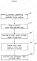
- a method of manufacturing the printed matter 10 is described with reference to FIG. 6 .
- a reference target surface to be printed is imaged and scanned (step S1 in FIG. 6 ). More specifically, for example, a charge-coupled device (CCD) camera, a complementary metal-oxide-semiconductor (CMOS) camera, or the like images a surface portion of an object to be reproduced, and surface irregularities are measured using a laser displacement measuring device or the like. At this time, imaged positions and positions of measured surface irregularities are associated with each other.
- CCD charge-coupled device
- CMOS complementary metal-oxide-semiconductor
- the four colors CMYK and height of convex portions are calculated for each position from data obtained by the imaging and scanning, and are stored in a memory or the like (step S2 in FIG. 6 ).
- Bump data is sequentially read from the memory and clear ink is applied and dried to layer clear element layers on/above a top surface of the light diffusion plate (substrate) 100 according to the bump data (step S31 in FIG. 6 ).
- the laminated clear layer 101 is configured to have four clear element layers 102-105, but the number of layers is changed according to the bump data.
- Color data is sequentially read from the memory, and the color layer 106 is formed so as to cover a top surface and side surfaces of the laminated clear layer 101 (step S32, FIG. 6 ).
- the color layer 106 is formed, for example, by using an inkjet device to apply ultraviolet (UV) curable ink containing a pigment for each color and curing the ink by using UV irradiation.
- UV ultraviolet
- two or more color layers can be formed.
- the light adjustment layer 107 is formed so as to cover the color layer 106 and an exposed surface of the light diffusion plate 100 (step S33 of FIG. 6 ).
- UV curable ink containing white particles made of a white pigment for example, titanium oxide
- step S3 of FIG. 6 printing (step S3 of FIG. 6 ) is completed and the printed matter 10 is completed.
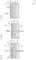
- FIG. 7A corresponds to FIG. 3A of Embodiment 1, and other configurations of the printed matter 30 can be the same as those of Embodiment 1.
- a laminated clear layer 301 which is a layered body of seven clear element layers 302, 303, 304, 305, 306, 307, 308, a light adjustment layer 309, and a color layer 310 are layered in this order in the Z axis direction from the top surface of the light diffusion plate 100.
- Points of difference from Embodiment 1 are that the number of clear element layers 302-308 of the laminated clear layer 301 is seven, and the light adjustment layer 309 is disposed below the color layer 310.
- each of the clear element layers 302-308 of the laminated clear layer 301 have a thickness from 0.010 mm to 0.030 mm, for example.
- the backlight 20 is disposed on a back surface 30b of the printed matter 30 pertaining to the present invention, and when the LED 21 is lit, incident light L 7 is transmitted through the printed matter 30 and emitted from a front surface 30a.
- the light adjustment layer 309 of the present embodiment is formed so as to cover from 2 % to 50 % (for example, 30 %) of the surface of the clear element layer 308 thereunder. More specifically, the light adjustment layer 309 is formed in a dot pattern, as in Embodiment 1.
- the printed matter 30 pertaining to the present embodiment even when surface irregularity 302a is present at surfaces of the clear element layers 302-308 as shown in FIG. 7B , influence of irregular reflection caused by the unevenness 302a can be suppressed by the light adjustment layer 309. That is, if light progressing in an oblique direction angled away from the Z axis direction due to irregular reflection is directly incident on the color layer 310, wavelength of emitted light changes due to a long optical path.
- the light adjustment layer 309 interposing the light adjustment layer 309 between the laminated clear layer 301 and the color layer 310, it is possible to change an optical path of light progressing at an oblique angle to be directed upward in the Z axis direction. This is due to a high probability that light incident on the light adjustment layer 309 in an oblique direction irradiates white particles in the light adjustment layer 309.
- the printed matter pertaining to the present embodiment it is possible to suppress influence of irregular reflection caused by the laminated clear layer 301 when light L 7 from a backlight is incident on the laminated clear layer 301, and the printed matter pertaining to the present embodiment is appropriate in situations such as when the number of clear element layers is increased to adopt an image having a sense of depth, such as a photograph.
- the number of clear element layers of the laminated clear layer 301 is seven according to the present embodiment, eight or more layers (for example, 10 layers) may be used. Thus, a sense of image depth can be increased.
- FIG. 8A also corresponds to FIG. 3A of Embodiment 1, and other configurations of the printed matter 40 can be the same as those of Embodiment 1.
- the laminated clear layer 301 which is a layered body of seven clear element layers, the light adjustment layer 309, the color layer 310, and a protective layer 411 are layered in this order in the Z axis direction from the top surface of the light diffusion plate 100.
- a point of difference from Embodiment 2 is that the protective layer 411 covers a top surface of the color layer 310.
- the protective layer 411 is formed using a hard resin material.
- a hard resin material for example, polypropylene (PP), acrylic resin (PMMA), styrene acrylonitrile resin (SAN), acrylonitrile butadiene styrene (ABS) resin, polycarbonate (PC), or the like can be used.
- density of the light adjustment layer 309 is also from 2 % to 50 % (for example, 30 %). More specifically, the light adjustment layer 309 is formed in a dot pattern, as in Embodiment 1.
- the color layer 310 when the color 310 is covered by the protective layer 411, the color layer 310 is protected when a person touches a printed matter surface, and deterioration of the color layer 310, the light adjustment layer 309, and the laminated clear layer 301 due to moisture and the like can be suppressed. In particular, even in a case in which printed matter to which an ink embossing process is applied is touched by a person, the color layer 310 can be reliably protected.
- Configuration of printed matter 45 pertaining to a modification is described with reference to FIG. 8B .
- the present modification is similar to the printed matter 40 pertaining to Embodiment 3, and configuration of portions that are not illustrated is the same as in Embodiment 1, as in Embodiment 3.
- a top surface of the protective layer 451 is processed to be irregular (surface irregularities 451a), thereby forming a matt finish. It is not always necessary to provide the surface irregularities 451a of the protective layer 451 to the entire surface of the protective layer 451, and in consideration of an image, both a glossy protective layer 411 as shown in FIG. 8A and a matt protective layer 451 as shown in FIG. 8B can be provided.
- density of the light adjustment layer 309 is also from 2 % to 50 % (for example, 30 %). More specifically, the light adjustment layer 309 is formed in a dot pattern, as in Embodiment 1.
- the color layer 310 can be protected, and an texture of an image formed by the color layer 310 can be increased by the matt finish of the protective layer 451.
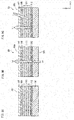
- FIG. 9A, FIG. 9B, and FIG. 9C Configuration of printed matter 50 pertaining to Embodiment 4 is described with reference to FIG. 9A, FIG. 9B, and FIG. 9C .
- FIG. 9A, FIG. 9B, and FIG. 9C parts having the same reference signs as above have the same configuration as described above, and description thereof is not repeated below. Further, configuration of other parts that are not illustrated is the same as in Embodiment 1.
- a second light adjustment layer 512 is disposed between the top surface of the light diffusion plater 100 and the laminated clear layer 101.
- Configurations of the laminated clear layer 101, the color layer 106, and the light adjustment layer 107 are the same as that of the printed matter 10 pertaining to Embodiment 1.
- Configuration of the second light adjustment layer 512 interposed between the light diffusion plate 100 and the laminated clear layer 101 is essentially the same as that of the light adjustment layer 107 shown in FIG. 4B .
- density of the second light adjustment layer 512 (surface area ratio in plan view of the surface of the light diffusion plate 100 covered by the second light adjustment layer 512) is from 2 % to 50 % and is set to be higher than that of the light adjustment layer 107.
- the density of the second light adjustment layer 512 is set higher than that of the light adjustment layer 107 disposed above the second light adjustment layer 512 in consideration of reflection of light incident from above as a function of the second light adjustment layer 512. However, if the density of the second light adjustment layer 512 is made higher than 50 %, much of light from the backlight 20 incident thereon from the back surface of the light diffusion plate 100 is also blocked, so care must be taken. With respect to a partial region in plan view, when transmitted light is to be completely shielded, density can be higher than 50 % (for example, 100 %). This can be considered in relation to an image.
- the printed matter 50 pertaining to the present embodiment by adjusting density of the second light adjustment layer 512, high image quality can be ensured both in a case in which the LED 21 of the backlight 20 is lit and a case in which the LED 21 is not lit, i.e., both when a viewer perceives an image via transmitted light and when a viewer perceived an image via reflected light.
- the effect obtained by the upper-side disposition of the light adjustment layer 107 is the same as that of the printed matter 10 pertaining to Embodiment 1.
- Disposition of the second light adjustment layer 512 is not necessarily required to be between the light diffusion plate 100 and the laminated clear layer 101, and may be between any of the clear element layers 102-105 of the laminated clear layer 101. Further, the number of clear element layers of the laminated clear layer can also be appropriately changed in consideration of a relationship with an image.
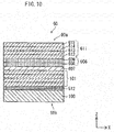
- FIG. 10 Configuration of printed matter 60 pertaining to Embodiment 5 is described with reference to FIG. 10 .
- parts assigned the same reference signs as in Embodiment 4 are configured to be the same as those of Embodiment 4, and are not described below. Further, configuration of other parts that are not illustrated is the same as in Embodiment 1.
- the second light adjustment layer 512, the laminated clear layer 101, and a light adjustment layer 607 are layered in this order on the top surface of the light diffusion plate 100.
- the light adjustment layer 607 has the same configuration as the light adjustment layer 107 of Embodiment 1 or 4, and the second light adjustment layer 512 is the same as in Embodiment 4.
- a laminated color layer 606 made of two color element layers 608, 609 is formed above the light adjustment layer 607 in the Z axis direction, and a laminated clear layer 611 made of four color element layers 612, 613, 614, 615 is layered thereon.
- the laminated color layer 606 made of the two color element layers 608, 609 is used in order to make color depth more noticeable for positions that are to be expressed with deep color.
- the laminated clear layer 611 is further formed on the laminated color layer 606 in order to further enhance texture of a deep color part of an image.
- densities of the light adjustment layer 607 and the second light adjustment layer 512 are each from 2 % to 50 %, in terms of surface area ratio in plan view.
- the printed matter 60 that has the above configuration, high image quality can be realized both in a case in which light is incident from a back surface 60b and a viewer perceives an image via transmitted light and in a case in which light is incident from a front surface 60a and a viewer perceives an image via reflected light. Further, according to the printed matter 60 pertaining to the present embodiment, texture at deep color positions can be increased by the laminated color layer 606 by use of the configuration shown in FIG. 10 .
- FIG. 11A Configuration of printed matter 70 pertaining to Embodiment 6 is described with reference to FIG. 11A .
- parts assigned the same reference signs as in Embodiment 1 are configured to be the same as those of Embodiment 1.
- the laminated clear layer 101, and the light adjustment layer 107 are layered in this order on the top surface of the light diffusion plate 100.
- the light adjustment layer 107 has the same configuration as in Embodiment 1.
- the printed matter 70 pertaining to the present embodiment is different from the printed matter 10 pertaining to Embodiment 1 in that a color layer is not provided, and the light adjustment layer 107 is layered directly on the laminated clear layer 101.
- Density of the light adjustment layer 107 pertaining to the present embodiment is also from 2 % to 50 %, in terms of surface area ratio in plan view.
- the printed matter 70 having the configuration described above can also achieve high image quality by suppressing yellowing when light is incident from a back surface and an image (a white image) is perceived via transmitted light.
- high image quality can be achieved for an image formed by using the printed matter 70 both when perceived via transmitted light and when perceived via reflected light.
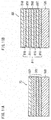
- a clear layer 812, a light adjustment layer 807, a clear layer 813, a light adjustment layer 808, a clear layer 814, a light adjustment layer 809, a clear layer 815, and a light adjustment layer 810 are layered in this order.
- the light adjustment layers 807, 808, 809 are interposed between the four layers of a laminated clear layer 811.
- Density of the light adjustment layers 807-810 is 7 % for the light adjustment layers 807, 808, 809 and 10 % for the light adjustment layer 810. Thickness of each of the light adjustment layers 807-810 is from 0.010 mm to 0.030 mm, or more preferably from 0.010 mm to 0.020 mm (for example, 0.020 mm).
- a total of densities of the light adjustment layers 807-810 of the printed matter 80 is 31 % (7 % ⁇ 3 + 10 %), and this is considered to be the "density of the light adjustment layer".
- the printed matter 80 having the configuration described above can also achieve high image quality by suppressing yellowing when light is incident from a back surface and an image (a white image) is perceived via transmitted light.
- high image quality can be achieved for an image formed by using the printed matter 80 both when perceived via transmitted light and when perceived via reflected light.
- a viewer can experience more sense of depth due to the alternation of the clear layers 812-815 and the light adjustment layers 807-810. This is attributable to the fact that dots of the light adjustment layers 807-810 are slighted shifted in an X-Y plane direction, and it is considered that a sense of depth is imparted due to refraction of light in oblique directions due to misalignment of the dots. Misalignment of the dots of the light adjustment layers 807-810 may be provided intentionally at the time of manufacture or may be achieved by using accuracy variation of an inkjet device.
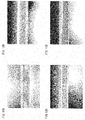
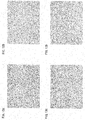
- FIG. 12A, 12B, 12C, 12D Transmission of light incident on a back surface of printed matter is described with reference to FIG. 12A, 12B, 12C, 12D , and FIG. 13A, 13B, 13C, 13D .
- FIG. 12A, 12B, 12C, 12D , and FIG. 13A, 13B, 13C, 13D show transmission states of the printed matter 70 pertaining to Embodiment 6 and the printed matter 80 pertaining to Embodiment 7.
- FIG. 12A is a cross section image taken along a scanning direction of an inkjet head when ink is applied to the printed matter 70
- FIG. 12C is a cross section image taken perpendicular to the scanning direction of the inkjet head.
- FIG. 13A is an image captured from directly above a light emitting side of the printed matter 70
- FIG. 13C is an image captured from an oblique angle above the light emitting side of the printed matter 70.
- FIG. 12B is a cross section image taken along a scanning direction of an inkjet head when ink is applied to the printed matter 80
- FIG. 12D is a cross section image taken perpendicular to the scanning direction of the inkjet head.
- FIG. 13B is an image captured from directly above a light emitting side of the printed matter 80
- FIG. 13D is an image captured from an oblique angle above the light emitting side of the printed matter 80.
- the laminated clear layers 101, 301 directly below the light adjustment layers 107, 309, 607 are composed of the clear element layers 102-105, 302-308 in a pyramid shape in cross section, and top and side surfaces thereof are covered by the light adjustment layers 107, 309, 607. Further, according to Embodiment 7, the clear layers 812-815 alternate with the light adjustment layers 807-810.
- the light adjustment layers 107, 309, 607, 807-810 are provided to suppress coloring of light, in particular transmitted light, due to clear element layers, and to realize high image quality both when an image is perceived via transmitted light and when an image is perceived via reflected light.
- the light adjustment layers 107, 309, 607, 807-810 are provided for light that is transmitted from side surfaces of the clear element layers 102-105, 302-308, 812-815 that constitute the laminated clear layers 101, 301, 807-810 when light from the backlight 20 irradiates a back surface. That is, it is possible for a viewer to perceive a high quality image due to formation of the image on an entire area visible to the viewer and due to the disposition of the light adjustment layers 107, 309, 607, 807-810.
- the light adjustment layers 107, 309, 607 so as to cover the laminated clear layers 101, 301, it is also possible to emphasize texture of deep colors and sense of depth of an image.
- the laminated clear layers 101, 611, 811 are composed of four clear element layers 102-105, 612-615, 812-815, respectively, and the laminated clear layer 301 is composed of seven clear element layers 302-308.
- the number of layers of a laminated clear layer is appropriately defined in relation to each position of an image to be expressed by the color layer. For example, the number of layers may be changed according to a surface condition of cloth, wood, leather, metal, and the like.
- Light adjustment layer density (light adjustment layer coverage of a surface of a layer thereunder, in terms of surface area ratio in plan view) is described with reference to FIG. 14A to FIG. 14O , and FIG. 15A to FIG. 15G .
- the density of a light adjustment layer can be appropriately set taking into account a number of clear layers formed, color of a color layer, texture of an image to be expressed, and the like.
- UV ink is applied by an inkjet device, and the UV ink is dried to form a light adjustment layer.
- a light adjustment layer is formed through a process of ink application and drying, there is a correlation between density and thickness (minimum thickness) of the light adjustment layer. Correlation between density and thickness of a light adjustment layer is shown in Table 1.
- thickness indicates a maximum height of a dot (see FIG. 4B ) of a light adjustment layer.
- the light diffusion plate 100 is used as the substrate, but the present invention is not limited to this example.
- a substrate made of resin or glass can be used.
- the degree of freedom in selection of material for use as a substrate increases, and appropriate selection can be made in consideration of image quality.
- a substrate made of resin or glass it is preferable to use a glossy material in consideration of light transmission rate, but a matt material (a material subjected to a matt treatment) can also be used in consideration of an image to be formed.
- the substrate it is possible to use a flexible substrate such as a film, or a substrate such as Japanese paper or thinly-sliced wood.
- the light adjustment layers 107, 309, 607, 807-810 and the second light adjustment layer 512 are printed in a dot pattern by using an inkjet device, but the present invention is not limited to this example.
- CVD chemical vapor deposition
- light reflecting particles included in the light adjustment layer particles made of material other than titanium oxide, reflective coating on surfaces of light-transmissive resin, or the like can be used.
- a particle shape of the light reflecting particles is not limited to a spherical shape. For example, cylindrical or polyhedral shapes can be used.
- the light adjustment layer when forming the light adjustment layer on a surface of an underlying layer, the light adjustment layer is not required to be in a dot pattern.
- halftone can be used, and a form can be used in which adjacent dots are connected to each other.
- the color layers 106, 310 and the laminated color layer 606 are formed by printing four colors of ink (C, M, Y, K), but the present invention is not limited to this example.
- the present invention is not limited to this example.
- three or less of the four colors can be used, and six colors can be used, adding colors such as light cyan (LC) and light magenta (KM) to the four colors.
- LC light cyan
- KM light magenta
- fluorescent ink phosphorescent ink, or the like can also be used.
- blacklight ink or the like can be used.
- monotone printing is included according to the printed matter of the present invention.
- the printed matter 10, 30, 40, 45, 50, 60, 70, 80 is used as a part of the illumination device 1, but the present invention is not limited to this example, and the printed matter can achieve the effects described above independently.
- the printed matter can achieve the effects described above when attached to an existing lighting device or a building window.
- an "edge light” device is used as a backlight, but the present invention is not limited to this example.
- a direct type of backlight can be used.
- a light guide plate is not necessarily required.
- a configuration without a light guide plate can be used.
- the LED 21 is used as a light source, but the present invention is not limited to this example.
- a hot cathode lamp, a cold cathode lamp, an inorganic EL lamp, an organic EL lamp, or the like can be used.
- light-emission color of a light source is not limited to white, and various wavelength ranges of emitted light may be used. It is also possible to adjust wavelength range of light absorbed and reflected by the light adjustment layer according to the wavelength range of light emitted from the light source.
- a wavelength conversion member in the light path to convert the light to white.
- a wavelength conversion member a wavelength conversion film including a phosphor layer or semiconductor quantum dots can be used.
- the present invention can be used in combination with a display panel or the like.
- a display panel for example, a liquid crystal display panel, an organic EL panel, an inorganic EL panel, etc.
- a configuration without a light guide plate can be used.
- the present invention can be used to realize digital signage in combination with a projector.
- the term "lighting" in connection with the present invention is used to include display devices and the like.
- the light adjustment layer is disposed above the laminated clear layer and/or interposed between clear element layers, and therefore high image quality is realized both in a case in which an image is perceived via transmitted light and in a case in which an image is perceived via reflected light.
- the phrase "high image quality” also means, for example, that a difference in image quality as perceived by a viewer is suppressed between a case in which an image is perceived via transmitted light and a case in which an image is perceived via reflected light.
- the present invention is useful for implementing printed matter that can achieve high image quality both in a case in which a viewer perceives an image via transmitted light and in a case in which a viewer perceives an image via reflected light, as part of interior decoration, advertisement medium, or building material (wall, ceiling, and the like).
Landscapes
- Physics & Mathematics (AREA)
- General Physics & Mathematics (AREA)
- Engineering & Computer Science (AREA)
- Theoretical Computer Science (AREA)
- Geometry (AREA)
- Illuminated Signs And Luminous Advertising (AREA)
- Printing Methods (AREA)
- Optical Elements Other Than Lenses (AREA)
- Planar Illumination Modules (AREA)
- Laminated Bodies (AREA)
Applications Claiming Priority (3)
| Application Number | Priority Date | Filing Date | Title |
|---|---|---|---|
| JP2014256215 | 2014-12-18 | ||
| JP2015084532A JP6385882B2 (ja) | 2014-12-18 | 2015-04-16 | 印刷物および照明装置 |
| PCT/JP2015/085016 WO2016098756A1 (ja) | 2014-12-18 | 2015-12-15 | 印刷物 |
Publications (2)
| Publication Number | Publication Date |
|---|---|
| EP3236455A1 true EP3236455A1 (de) | 2017-10-25 |
| EP3236455A4 EP3236455A4 (de) | 2018-10-31 |
Family
ID=56244217
Family Applications (1)
| Application Number | Title | Priority Date | Filing Date |
|---|---|---|---|
| EP15869961.1A Withdrawn EP3236455A4 (de) | 2014-12-18 | 2015-12-15 | Drucksache |
Country Status (5)
| Country | Link |
|---|---|
| US (1) | US11020998B2 (de) |
| EP (1) | EP3236455A4 (de) |
| JP (1) | JP6385882B2 (de) |
| CN (1) | CN107111975B (de) |
| TW (1) | TWI685824B (de) |
Cited By (1)
| Publication number | Priority date | Publication date | Assignee | Title |
|---|---|---|---|---|
| CN111989215A (zh) * | 2018-05-30 | 2020-11-24 | 日本电气硝子株式会社 | 带有调光功能的层叠体 |
Families Citing this family (18)
| Publication number | Priority date | Publication date | Assignee | Title |
|---|---|---|---|---|
| DE102015117401A1 (de) * | 2015-10-13 | 2017-04-13 | Airbus Operations Gmbh | Flugzeugkabinenanordnung |
| JP7130219B2 (ja) * | 2016-10-24 | 2022-09-05 | タイガー魔法瓶株式会社 | 真空二重容器 |
| JP2018072700A (ja) * | 2016-11-02 | 2018-05-10 | 正寿 戸田 | 観賞物およびその展示室 |
| USD853733S1 (en) * | 2017-06-09 | 2019-07-16 | Suominen Corporation | Material sheet with patterned surface |
| US11119263B2 (en) | 2017-06-22 | 2021-09-14 | Xerox Corporation | System and method for image specific illumination of image printed on optical waveguide |
| US10539732B2 (en) | 2017-06-22 | 2020-01-21 | Xerox Corporation | System and method for image specific illumination of image printed on optical waveguide |
| US11249240B2 (en) | 2017-06-22 | 2022-02-15 | Xerox Corporation | System and method for image specific illumination of image printed on optical waveguide |
| US20180372630A1 (en) * | 2017-06-22 | 2018-12-27 | Xerox Corporation | System and method for image specific illumination of image printed on optical waveguide |
| US10168279B1 (en) | 2017-06-22 | 2019-01-01 | Xerox Corporation | System and method for image specific illumination of image printed on optical waveguide |
| USD929747S1 (en) * | 2017-11-22 | 2021-09-07 | Dsm Ip Assets B.V. | Film sheet for antiballistic articles |
| JP6982830B2 (ja) * | 2017-11-29 | 2021-12-17 | パナソニックIpマネジメント株式会社 | 照明装置、及び、照明装置の製造方法 |
| JP2019144455A (ja) * | 2018-02-22 | 2019-08-29 | 凸版印刷株式会社 | 埋め込み型の表示パネル |
| JP7241278B2 (ja) * | 2019-03-08 | 2023-03-17 | パナソニックIpマネジメント株式会社 | 照明装置、及び、照明装置の製造方法 |
| JP7285447B2 (ja) * | 2019-06-11 | 2023-06-02 | パナソニックIpマネジメント株式会社 | 照明装置、及び、照明装置の製造方法 |
| JP6972096B2 (ja) * | 2019-12-27 | 2021-11-24 | 俊一 朝野 | 立体印刷物、及び立体印刷物の形成方法 |
| USD1003632S1 (en) * | 2020-03-03 | 2023-11-07 | David Matthew Pedicini | Cup placement mat |
| CN112123960B (zh) * | 2020-09-27 | 2022-04-01 | 捷卡(厦门)工业科技有限公司 | 一种打印导光点的导光板制作方法 |
| JP7710050B2 (ja) * | 2022-01-12 | 2025-07-17 | 俊一 朝野 | 立体印刷物、及び立体印刷物の製造方法 |
Family Cites Families (19)
| Publication number | Priority date | Publication date | Assignee | Title |
|---|---|---|---|---|
| JPH05131799A (ja) | 1991-11-08 | 1993-05-28 | Shinichiro Arakawa | 描画構造と描画方法 |
| US5407711A (en) * | 1993-11-30 | 1995-04-18 | Signs & Glassworks, Incorporated | Display with enhanced highlights |
| GB9600247D0 (en) * | 1996-01-06 | 1996-03-06 | Contra Vision Ltd | Panel with light permeable images |
| JPH11143414A (ja) * | 1997-11-12 | 1999-05-28 | Casio Comput Co Ltd | 化粧部材 |
| JP2001255606A (ja) | 2000-03-10 | 2001-09-21 | Seiko Epson Corp | 立体画像形成装置及びそれを用いた立体画像の形成方法 |
| GB0114635D0 (en) * | 2001-06-15 | 2001-08-08 | Hills Hi Speed Plates Ltd | Identification plates |
| JP4358653B2 (ja) | 2003-02-26 | 2009-11-04 | 富士フイルム株式会社 | 立体イメージの形成方法および装置 |
| DE602004000876T2 (de) | 2003-02-26 | 2007-02-15 | Fuji Photo Film Co., Ltd., Minami-Ashigara | Verfahren und Gerät zur Bildung eines dreidimensionalen Bildes |
| JP4248974B2 (ja) * | 2003-09-02 | 2009-04-02 | 日東電工株式会社 | 光源装置および液晶表示装置 |
| JP2008087287A (ja) | 2006-09-29 | 2008-04-17 | Fujifilm Corp | インク吐出不良検出方法および画像形成装置 |
| US8623467B2 (en) | 2007-12-17 | 2014-01-07 | Ricoh Co., Ltd. | Tactile printing |
| JP5146230B2 (ja) | 2008-09-29 | 2013-02-20 | 大日本印刷株式会社 | エンボス同調化粧シート |
| WO2010073726A1 (ja) * | 2008-12-25 | 2010-07-01 | 三菱レイヨン株式会社 | 光源装置用導光体及びその製造方法 |
| JP5391369B1 (ja) * | 2010-11-08 | 2014-01-15 | ウー‐ニカ テクノロギー アーゲー | 顔料が付された基板にuvレーザーを照射することでカラー画像を生成する方法及び装置並びにそれらにより生成される生成物。 |
| AU2011101684B4 (en) * | 2011-12-22 | 2012-08-16 | Innovia Security Pty Ltd | Optical Security Device with Nanoparticle Ink |
| JP2013230625A (ja) | 2012-04-27 | 2013-11-14 | Mimaki Engineering Co Ltd | 印刷方法および印刷装置 |
| JP6056191B2 (ja) * | 2012-05-15 | 2017-01-11 | カシオ計算機株式会社 | 印刷物、印刷方法、画像形成装置、及び、プログラム |
| WO2014134752A1 (zh) * | 2013-03-08 | 2014-09-12 | Hwang Yu-Chen | 一种多功能电子窗及其制造方法 |
| JP2014203671A (ja) * | 2013-04-04 | 2014-10-27 | 株式会社ミマキエンジニアリング | バックライト導光板、バックライト導光板製造方法及びインクジェットプリンタ |
-
2015
- 2015-04-16 JP JP2015084532A patent/JP6385882B2/ja active Active
- 2015-12-07 TW TW104140943A patent/TWI685824B/zh active
- 2015-12-15 EP EP15869961.1A patent/EP3236455A4/de not_active Withdrawn
- 2015-12-15 CN CN201580068899.3A patent/CN107111975B/zh active Active
- 2015-12-15 US US15/534,400 patent/US11020998B2/en active Active
Cited By (1)
| Publication number | Priority date | Publication date | Assignee | Title |
|---|---|---|---|---|
| CN111989215A (zh) * | 2018-05-30 | 2020-11-24 | 日本电气硝子株式会社 | 带有调光功能的层叠体 |
Also Published As
| Publication number | Publication date |
|---|---|
| JP2016118754A (ja) | 2016-06-30 |
| TWI685824B (zh) | 2020-02-21 |
| EP3236455A4 (de) | 2018-10-31 |
| JP6385882B2 (ja) | 2018-09-05 |
| US20170368860A1 (en) | 2017-12-28 |
| US11020998B2 (en) | 2021-06-01 |
| CN107111975A (zh) | 2017-08-29 |
| CN107111975B (zh) | 2020-05-01 |
| TW201636976A (zh) | 2016-10-16 |
Similar Documents
| Publication | Publication Date | Title |
|---|---|---|
| US11020998B2 (en) | Printed matter | |
| JP6007195B2 (ja) | 高い反射率を有するカラーレーザ画像を形成する方法、及び、カラーレーザ画像がこの方法で作製されたドキュメント | |
| US10112429B2 (en) | Method of forming a color laser image, and resulting document | |
| US20080062172A1 (en) | 2d/3d display and method for forming 3d image | |
| US20120170072A1 (en) | Display device | |
| US7948577B2 (en) | Stereoscopic display device | |
| KR20110096086A (ko) | 오토스테레오스코픽 디스플레이 디바이스 | |
| US10129533B2 (en) | High quality and moire-free 3D stereoscopic image rendering system using a lenticular lens | |
| CN110379934A (zh) | 一种显示面板及显示装置 | |
| CN114545648A (zh) | 一种显示面板及其制作方法 | |
| CN105607271B (zh) | 一种显示模组、显示装置及其驱动方法 | |
| CN105892079A (zh) | 一种显示装置 | |
| US20140226188A1 (en) | Image recombination structure | |
| US20070236619A1 (en) | Image display device | |
| JP6972096B2 (ja) | 立体印刷物、及び立体印刷物の形成方法 | |
| WO2016098756A1 (ja) | 印刷物 | |
| US12043056B2 (en) | Method for manufacturing a card | |
| HK1240387A1 (en) | Printed matter | |
| HK1240387B (zh) | 印刷物 | |
| JP4657010B2 (ja) | 立体印刷方法およびそれによる立体印刷体 | |
| US12222604B2 (en) | Wavelength conversion element and backlight module | |
| KR101728220B1 (ko) | 3d 영상 디스플레이용 도광판 | |
| EP4457798A1 (de) | Farbumwandlungssubstrat und anzeigevorrichtung | |
| JP2007173052A (ja) | 照明装置 | |
| CN106959541A (zh) | 显示基板、显示面板和显示装置 |
Legal Events
| Date | Code | Title | Description |
|---|---|---|---|
| STAA | Information on the status of an ep patent application or granted ep patent |
Free format text: STATUS: THE INTERNATIONAL PUBLICATION HAS BEEN MADE |
|
| PUAI | Public reference made under article 153(3) epc to a published international application that has entered the european phase |
Free format text: ORIGINAL CODE: 0009012 |
|
| STAA | Information on the status of an ep patent application or granted ep patent |
Free format text: STATUS: REQUEST FOR EXAMINATION WAS MADE |
|
| 17P | Request for examination filed |
Effective date: 20170718 |
|
| AK | Designated contracting states |
Kind code of ref document: A1 Designated state(s): AL AT BE BG CH CY CZ DE DK EE ES FI FR GB GR HR HU IE IS IT LI LT LU LV MC MK MT NL NO PL PT RO RS SE SI SK SM TR |
|
| AX | Request for extension of the european patent |
Extension state: BA ME |
|
| DAV | Request for validation of the european patent (deleted) | ||
| DAX | Request for extension of the european patent (deleted) | ||
| A4 | Supplementary search report drawn up and despatched |
Effective date: 20180928 |
|
| RIC1 | Information provided on ipc code assigned before grant |
Ipc: G09F 13/04 20060101AFI20180924BHEP Ipc: B41M 3/06 20060101ALN20180924BHEP Ipc: B44F 7/00 20060101ALI20180924BHEP Ipc: B44F 1/04 20060101ALI20180924BHEP Ipc: B44F 1/06 20060101ALI20180924BHEP |
|
| STAA | Information on the status of an ep patent application or granted ep patent |
Free format text: STATUS: EXAMINATION IS IN PROGRESS |
|
| 17Q | First examination report despatched |
Effective date: 20210325 |
|
| GRAP | Despatch of communication of intention to grant a patent |
Free format text: ORIGINAL CODE: EPIDOSNIGR1 |
|
| STAA | Information on the status of an ep patent application or granted ep patent |
Free format text: STATUS: GRANT OF PATENT IS INTENDED |
|
| INTG | Intention to grant announced |
Effective date: 20250131 |
|
| STAA | Information on the status of an ep patent application or granted ep patent |
Free format text: STATUS: THE APPLICATION IS DEEMED TO BE WITHDRAWN |
|
| 18D | Application deemed to be withdrawn |
Effective date: 20250603 |