EP3237287B1 - Sitzvorrichtung - Google Patents
Sitzvorrichtung Download PDFInfo
- Publication number
- EP3237287B1 EP3237287B1 EP15823165.4A EP15823165A EP3237287B1 EP 3237287 B1 EP3237287 B1 EP 3237287B1 EP 15823165 A EP15823165 A EP 15823165A EP 3237287 B1 EP3237287 B1 EP 3237287B1
- Authority
- EP
- European Patent Office
- Prior art keywords
- unit
- seat
- backrest
- passenger
- area
- Prior art date
- Legal status (The legal status is an assumption and is not a legal conclusion. Google has not performed a legal analysis and makes no representation as to the accuracy of the status listed.)
- Active
Links
Images


Classifications
-
- B—PERFORMING OPERATIONS; TRANSPORTING
- B64—AIRCRAFT; AVIATION; COSMONAUTICS
- B64D—EQUIPMENT FOR FITTING IN OR TO AIRCRAFT; FLIGHT SUITS; PARACHUTES; ARRANGEMENT OR MOUNTING OF POWER PLANTS OR PROPULSION TRANSMISSIONS IN AIRCRAFT
- B64D11/00—Passenger or crew accommodation; Flight-deck installations not otherwise provided for
- B64D11/06—Arrangements of seats, or adaptations or details specially adapted for aircraft seats
- B64D11/0639—Arrangements of seats, or adaptations or details specially adapted for aircraft seats with features for adjustment or converting of seats
- B64D11/064—Adjustable inclination or position of seats
-
- B—PERFORMING OPERATIONS; TRANSPORTING
- B60—VEHICLES IN GENERAL
- B60N—SEATS SPECIALLY ADAPTED FOR VEHICLES; VEHICLE PASSENGER ACCOMMODATION NOT OTHERWISE PROVIDED FOR
- B60N2/00—Seats specially adapted for vehicles; Arrangement or mounting of seats in vehicles
- B60N2/02—Seats specially adapted for vehicles; Arrangement or mounting of seats in vehicles the seat or part thereof being movable, e.g. adjustable
- B60N2/22—Seats specially adapted for vehicles; Arrangement or mounting of seats in vehicles the seat or part thereof being movable, e.g. adjustable the back-rest being adjustable
- B60N2/2222—Seats specially adapted for vehicles; Arrangement or mounting of seats in vehicles the seat or part thereof being movable, e.g. adjustable the back-rest being adjustable the back-rest having two or more parts
-
- B—PERFORMING OPERATIONS; TRANSPORTING
- B60—VEHICLES IN GENERAL
- B60N—SEATS SPECIALLY ADAPTED FOR VEHICLES; VEHICLE PASSENGER ACCOMMODATION NOT OTHERWISE PROVIDED FOR
- B60N2/00—Seats specially adapted for vehicles; Arrangement or mounting of seats in vehicles
- B60N2/68—Seat frames
- B60N2/686—Panel like structures
-
- B—PERFORMING OPERATIONS; TRANSPORTING
- B60—VEHICLES IN GENERAL
- B60N—SEATS SPECIALLY ADAPTED FOR VEHICLES; VEHICLE PASSENGER ACCOMMODATION NOT OTHERWISE PROVIDED FOR
- B60N2/00—Seats specially adapted for vehicles; Arrangement or mounting of seats in vehicles
- B60N2/70—Upholstery springs ; Upholstery
- B60N2/7011—Upholstery springs ; Upholstery of substantially two-dimensional shape, e.g. hammock-like, plastic shells, fabrics
-
- B—PERFORMING OPERATIONS; TRANSPORTING
- B60—VEHICLES IN GENERAL
- B60N—SEATS SPECIALLY ADAPTED FOR VEHICLES; VEHICLE PASSENGER ACCOMMODATION NOT OTHERWISE PROVIDED FOR
- B60N2/00—Seats specially adapted for vehicles; Arrangement or mounting of seats in vehicles
- B60N2/80—Head-rests
- B60N2/806—Head-rests movable or adjustable
- B60N2/809—Head-rests movable or adjustable vertically slidable
-
- B—PERFORMING OPERATIONS; TRANSPORTING
- B64—AIRCRAFT; AVIATION; COSMONAUTICS
- B64D—EQUIPMENT FOR FITTING IN OR TO AIRCRAFT; FLIGHT SUITS; PARACHUTES; ARRANGEMENT OR MOUNTING OF POWER PLANTS OR PROPULSION TRANSMISSIONS IN AIRCRAFT
- B64D11/00—Passenger or crew accommodation; Flight-deck installations not otherwise provided for
- B64D11/06—Arrangements of seats, or adaptations or details specially adapted for aircraft seats
- B64D11/0639—Arrangements of seats, or adaptations or details specially adapted for aircraft seats with features for adjustment or converting of seats
- B64D11/0641—Seats convertible into beds
-
- B—PERFORMING OPERATIONS; TRANSPORTING
- B64—AIRCRAFT; AVIATION; COSMONAUTICS
- B64D—EQUIPMENT FOR FITTING IN OR TO AIRCRAFT; FLIGHT SUITS; PARACHUTES; ARRANGEMENT OR MOUNTING OF POWER PLANTS OR PROPULSION TRANSMISSIONS IN AIRCRAFT
- B64D11/00—Passenger or crew accommodation; Flight-deck installations not otherwise provided for
- B64D11/06—Arrangements of seats, or adaptations or details specially adapted for aircraft seats
- B64D11/0646—Seats characterised by special features of stationary arms, foot or head rests
-
- Y—GENERAL TAGGING OF NEW TECHNOLOGICAL DEVELOPMENTS; GENERAL TAGGING OF CROSS-SECTIONAL TECHNOLOGIES SPANNING OVER SEVERAL SECTIONS OF THE IPC; TECHNICAL SUBJECTS COVERED BY FORMER USPC CROSS-REFERENCE ART COLLECTIONS [XRACs] AND DIGESTS
- Y02—TECHNOLOGIES OR APPLICATIONS FOR MITIGATION OR ADAPTATION AGAINST CLIMATE CHANGE
- Y02T—CLIMATE CHANGE MITIGATION TECHNOLOGIES RELATED TO TRANSPORTATION
- Y02T50/00—Aeronautics or air transport
- Y02T50/40—Weight reduction
Definitions
- the invention relates to a seat device according to the preamble of patent claim 1.
- a seat device in particular an aircraft passenger seat device, with at least one seat base unit and a backrest unit connected to the seat base unit, wherein at least the backrest unit can be positioned in a comfort position and another seat position, has already been proposed .
- the object of the invention consists in particular in providing a generic device with improved properties with regard to passenger comfort.
- the object is achieved according to the invention by the features of patent claim 1, while advantageous configurations and developments of the invention can be found in the dependent claims.
- the invention is based on a seat device, in particular an aircraft passenger seat device, with the features of claim 1.
- the comfort position be designed as a basic position optimized for passenger comfort.
- a “seat device” is to be understood in particular as a device which forms at least a part or an entire seat, such as in particular an aircraft passenger seat.
- the seat device forms in particular a passenger seat which is designed as an economy class seat or a premium economy class seat which is provided in particular for medium and/or long-haul flights.
- the seat device preferably forms in particular one Passenger seat with a floor area of more than 0.5 square meters available to one passenger.
- a “passenger seat” is to be understood in particular as meaning a seat that is elevated in an aircraft cabin of an aircraft.
- the passenger seat is preferably designed as part of one of a plurality of passenger seats arranged next to one another.
- the passenger seat includes in particular at least one seat floor unit that forms a seating area for a passenger, a backrest unit that provides a backrest support surface on which a passenger sitting on the passenger seat can support his back, and at least one armrest unit on which the passenger can Arm can at least partially store.
- a “seat floor unit” is to be understood in particular as a unit that forms the seating area for a passenger, with the seat floor unit preferably being formed by a base body and a cushion unit attached to the base body.
- a “seat area” is to be understood in particular as an area of the passenger seat that is provided for a passenger to sit on, in particular during a flight.
- the seat area is formed by the seat bottom unit, which preferably comprises at least one base body and an upholstery element that is attached to the base body and forms the seat area.
- a "backrest unit” is to be understood in particular as a unit of the aircraft passenger seat which forms a backrest support surface against which a passenger sitting on the aircraft seat can lean his back.
- the backrest unit preferably comprises at least one base body and one upholstery unit, which forms the backrest support surface.
- the backrest unit is arranged at a rear end of the seat base unit and extends upwards from the seat base unit, away from a stand unit.
- a “comfort position” is to be understood in particular as a position of the seat device in which a backrest unit of the seat device has a tilt pivoted backwards from a TTL position, which allows a passenger an advantageously comfortable, non-upright seated position.
- a “further seat position” is to be understood in particular as a seat position in which, in particular, the backrest unit has a different inclination to a cabin floor than in the comfort position.
- Another seating position is designed as a TTL position, for example.
- a “TTL position” is to be understood here in particular as an upright position of the passenger seat, which must be assumed for safety reasons, in particular during a take-off phase, in a landing phase and during turbulence.
- a backrest unit of the passenger seat and the seat bottom substantially perpendicular to each other, preferably at an angle of between 90 degrees and 105 degrees.
- the TTL position forms a first end position into which the aircraft seat can be maximally adjusted.
- a "basic position” is to be understood in particular as a position for which a seat, in particular a passenger seat, is designed and constructed.
- the backrest unit preferably forms an essentially flat, continuous surface.
- “Provided” is to be understood in particular as being specially designed and/or equipped.
- the fact that an object is provided for a specific function is to be understood in particular to mean that the object fulfills and/or executes this specific function in at least one application and/or operating state.
- a configuration according to the invention makes it possible to provide a particularly comfortable seat for a passenger; in particular, sleeping comfort can be increased and side sleeping made possible.
- the backrest unit has a rigid partial area which is rigidly coupled to the seat bottom unit.
- a “rigid sub-area” is to be understood in particular as a sub-area which is essentially not elastically deformable.
- “Rigidly coupled” is to be understood in particular as meaning that the two elements coupled to one another, such as in particular the rigid partial area of the backrest unit and the seat base unit, have a fixed, non-destructively unchangeable alignment with one another.
- the backrest unit and the seat base unit can be formed together, at least in part, particularly advantageously, as a result of which particularly advantageous ergonomics can be achieved for a passenger.
- the backrest unit has an upper section which is designed to be pivotable with respect to the lower, rigid section.
- An “upper partial area” is to be understood in particular as a partial area of the backrest unit that forms a part of the backrest unit that faces away from a stand unit.
- the upper partial area and the lower rigid partial area are preferably designed as separate components.
- “Pivotable” is to be understood here in particular as meaning that the orientation of the upper partial area and the lower partial area can be adjusted by rotating them relative to one another about a common pivot axis.
- a particularly advantageous backrest unit can thereby be provided be, which is particularly comfortable for a passenger in a comfort position and can continue to be moved into a necessary TTL position.
- the seat device forms at least one bearing unit, which supports the rigid lower section with the upper pivotable section, and a pivot axis that is offset forward in the seat direction with respect to a rear end of the backrest unit.
- a “bearing unit” is to be understood in particular as a sliding and/or rolling bearing, via which two elements connected to one another via the bearing unit, such as in particular the lower partial area and the upper partial area, can be pivoted relative to one another.
- “Shifted forward” is to be understood here in particular as meaning that the pivot axis is not arranged at a rear end of the backrest unit seen in the direction of the seat, but is shifted forward in the direction of the seat. A particularly advantageous pivoting of the lower partial area and the upper partial area relative to one another can thereby be achieved.
- the seat device has at least one contact element arranged laterally and extending forward from the backrest unit in a region of the bearing unit.
- a "contact element” is to be understood as meaning an element on which a passenger can support himself with part of his body.
- the seat device preferably has a contact element on both sides of the backrest unit.
- the backrest unit can be configured particularly advantageously in a comfortable manner.
- the backrest unit and the seat base unit have a seat angle of at least 120 degrees in the basic position.
- a “seat angle” is to be understood in particular as an angle which the backrest unit and the seat bottom unit have in relation to one another in a mounted state.
- a particularly comfortable and ergonomic seating position can be achieved.
- “At least 120 degrees” should be understood to mean that the seat angle between the backrest unit and the seat base unit is at least 120 degrees, preferably more than 125 degrees and in a particularly advantageous embodiment more than 130 degrees.
- the backrest unit in the basic position has an inclination of at least 120 degrees to a stand-on plane.
- a “stand-up plane” is to be understood in particular as a plane on which the passenger seat is raised with its stand-up unit.
- the stand-up plane is formed by a cabin floor of the aircraft in which the passenger seat is fitted.
- An "inclination of at least 120 degrees” should be understood to mean that an angle between the support plane and the backrest unit is at least 120 degrees, preferably 125 degrees and, in a particularly advantageous embodiment, 130 degrees.
- the backrest unit can be aligned particularly advantageously in the basic position.
- the seat area of the seat bottom unit has a base body which, at least in a front area, forms at least two partial areas that are separate from one another in a transverse direction and that are movable relative to each other at the same height.
- a “base body” is to be understood in particular as an element which is part of a load-bearing structure and is intended to transmit forces introduced into the seat bottom unit.
- “Partial areas that are separate from one another” are to be understood in particular as meaning two areas that are in particular spatially separated from one another, with a gap preferably being arranged between the two partial areas.
- a region between the two partial regions that are separated from one another is formed by a material that in particular has elastic properties, so that this material only marginally restricts movement of the partial regions relative to one another.
- a particularly advantageous seat bottom unit can be provided.
- the base body forms at least one slot, at least in its front area, which separates the at least two partial areas from one another.
- the partial areas can be designed in a particularly simple manner.
- the seat device has at least one armrest unit, which delimits the seat area laterally.
- An “armrest unit” is to be understood in particular as a unit that forms a part or preferably a complete armrest for a seat, in particular an aircraft passenger seat.
- the armrest unit forms at least one support surface on which a passenger sitting on the passenger seat can rest his arm at least partially.
- the armrest unit has at least one support element. This makes it particularly easy to create an element on which a passenger can at least partially rest his arm.
- the armrest unit has at least one supporting and/or separating element aligned essentially perpendicularly to the seat bottom unit and at least one support element pivotably connected thereto.
- a "support element” is to be understood in particular as an element which is preferably formed from an elastic, dimensionally stable material and has at least one surface which forms the support surface directly or indirectly. It is conceivable that the support element forms the support surface directly and a passenger comes into direct contact with the support element or that the armrest unit comprises at least one cushion element that covers the support element and thus forms the support surface, whereby the support element forms the support surface indirectly.
- the support element is preferably designed to be adjustable and can be adjusted at least between a rest position and a position of use.
- the support element is preferably pivotably mounted and can be pivoted between the rest position and the position of use. In principle, it is also conceivable that the support element can be displaced between the two positions in a different way, for example via a linear guide.
- a “supporting and/or separating element” is to be understood in particular as an element that separates an area, in particular the bearing surface of the armrest unit, from a bearing surface of an adjacent passenger seat or from another area of the aircraft, such as an aisle, and Support surface provides on which a passenger can be supported to the side.
- a “supporting surface of the supporting and/or separating element” is to be understood in particular as a surface which is aligned essentially perpendicular to the supporting surface of the supporting element and faces the seating area of the aircraft passenger seat.
- the support element can be pivoted should be understood in particular to mean that the support element can be pivoted between at least two positions via a bearing.
- the support element can preferably be pivoted between a rest position and a position of use.
- a "rest position of the support element” is to be understood in particular as a position of the support element in which the support surface of the support element cannot be used for the passenger to rest his arm and the support element is attached to the seat device in as space-saving a manner as possible.
- the rest position is designed as a position in which the passenger does not need the support element and in which the support element is arranged in the most space-saving and comfortable way possible for the passenger.
- a “position of use of the support element” is to be understood in particular as a position of the support element in which the support surface of the support element can be used by the passenger to rest his arm and the support element is folded away from the supporting and/or separating element. With the pivotable support element, a passenger can either rest his arm on the armrest unit or advantageously fold the support element away in order to use the resulting space differently.
- the seat device has at least one support element, with the support element spanning at least one area between the seat base unit, the armrest unit and/or the backrest unit.
- a “supporting element” is to be understood in particular as an element on which a passenger can support himself with part of his body, in particular with a lower, lateral back area.
- the support element is formed by an element which has a surface via which a force can be introduced into a supporting structure of the seat device.
- the support element can be formed by different elements. It is conceivable that the supporting element is formed by a cushion, an air cushion, an elastic plastic or a covering element, such as in particular a textile.
- the support element is preferably designed as a covering element.
- a “covering element” is to be understood in particular as meaning an elastic element that is stretched out in one area by attachment at several of its ends.
- the covering element is preferably formed by a textile, such as in particular a net.
- the covering element is formed from a thin-walled plastic, a fiber composite material or other materials that appear sensible to a person skilled in the art.
- the support element can advantageously provide lateral support, on which a passenger can support his back laterally and can assume a particularly comfortable position on the passenger seat.
- the support element adjoins a support surface of the support element when the support element is in a rest position.
- a “supporting surface of the support element” is to be understood in particular as a surface against which a passenger sitting on the passenger seat can lean, in particular laterally.
- the support surface is particularly padded.
- the support surface is arranged on a side of the support element that is opposite the support surface. In the folded position, the support surface faces the seating area.
- the backrest unit forms a backrest support surface which has a narrowing in a lower area.
- a “backrest support surface” is to be understood in particular as a surface that is available to the passenger to lean against with his back.
- a “lower area” is to be understood in particular as an area of the backrest unit that faces the seat bottom unit. The lower area takes up approximately the lower third of the backrest support surface.
- a “tapering” is to be understood here in particular as a region which has different widths over a defined length and which, seen from a starting point of the tapering, becomes ever narrower. As a result, a particularly advantageous and comfortable backrest support surface can be achieved.
- a layout is proposed in which at least two passenger seats are arranged one behind the other, with a backrest unit of the front passenger seat extending over a seat floor unit of the rear passenger seat in a comfort position.
- a "layout” should be understood to mean an arrangement of a plurality of aircraft passenger seats in an aircraft cabin. “Arranged one behind the other” is to be understood in particular as being arranged one behind the other in a row, with central axes of the passenger seats arranged one behind the other running parallel to the seat directions of the passenger seats being arranged coaxially to one another. The passenger seats arranged one behind the other are aligned in the same direction. In particular, the passenger seats are arranged at a pitch distance of 33 inches from one another.
- the pitch distance is formed by a distance between the elevation of two passenger seats arranged one behind the other.
- the pitch distance is, for example, by Measuring the distance between two identical components of the two seats arranged one behind the other, for example by measuring a distance between a front edge of the seat bottom unit of the front passenger seat and a front edge of the seat bottom unit of the rear passenger seat.
- measurements are taken parallel to the seat direction of the aircraft passenger seats, preferably parallel to a longitudinal axis of the aircraft cabin.
- the backrest unit of the front passenger seat overlaps over a seat floor unit of the rear passenger seat only in the comfort position. In a TTL position of the front passenger seat, there is in particular no overlapping of the backrest unit of the front passenger seat beyond a seat floor unit of the rear passenger seat.
- a particularly advantageous and space-saving arrangement of passenger seats in a layout can thereby be achieved.
- the backrest unit of the front passenger seat overlaps the seat bottom unit of the rear passenger seat by at least 3.5 inches in a comfort position.
- “At least 3.5 inches” is to be understood as meaning in particular at least 3.5 inches, advantageously at least 4 inches and in a particularly advantageous embodiment at least 5 inches mm.
- the overlap is, in particular with a pitch distance between the passenger seats of 33 inches, in particular at least 3.5 inches.
- the overlap of the backrest unit of the front passenger seat with the seat bottom unit of the rear passenger seat in the comfort position is at least one fifth, preferably at least one quarter of a length of the seat bottom unit of the rear passenger seat. In this way, a particularly advantageously compact layout can be provided.
- the seat device according to the invention should not be limited to the application and embodiment described above.
- the seat device according to the invention can have a number of individual elements, components and units that differs from a number specified here in order to fulfill a function described herein.
- the Figures 1 to 11 show a seat device according to the invention in a first embodiment.
- the seat device is designed as an aircraft passenger seat device.
- the seat device is designed as part of a seat, in particular as part of an aircraft passenger seat 10 .
- the passenger seat 10 is installed in a passenger cabin of an aircraft in an assembled state.
- the passenger cabin has a cabin floor on which the passenger seat 10 is elevated.
- the cabin floor forms an elevated level for the passenger seat 10 .
- Several passenger seats 10, 60, 62 with the seat device according to the invention are arranged in the passenger cabin.
- the passenger seats 10, 60, 62 are arranged in the passenger cabin in a layout described below.
- the passenger seats 10, 60 are arranged together in a seat row 64 side by side.
- the row of seats 64 is formed by three passenger seats 10, 60 arranged next to one another, one of which is not shown in detail in the drawings. In principle, it would also be conceivable for the row of seats 64 to have a different number of passenger seats 10, 60 or for the passenger seats 10, 60 to be in the form of individual seats that are not arranged in a row of seats. Only one aircraft passenger seat 10 with the seat device according to the invention designed as a passenger seat device is described below.
- the seat device has a stand unit 12 .
- the stand unit 12 is provided to stand the passenger seat 10 and the other passenger seats 60 of the same seat row 64 on the cabin floor.
- the stand unit 12 comprises a plurality of connecting elements, not shown in detail, which couple the stand unit 12 firmly to the cabin floor.
- the connecting elements are preferably provided to be arranged in a form-fitting manner in a fastening rail of the cabin floor and to be fixed in the fastening rail for the fixed connection of the row of seats 64 .
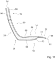
- the seat device comprises a seat bottom unit 14.
- the seat bottom unit 14 is intended to provide a seating area 16 on which a passenger can sit, in particular during a flight.
- the seating area 16 forms a seat surface on which the passenger sits.
- the seat bottom unit 14 is connected to the stand unit 12 .
- the seat bottom unit 14 is rigidly connected to the stand unit 12 .
- the seat bottom unit 14 is pivotably connected to the stand unit 12 via kinematics.
- the seat bottom unit 14 includes a base body 18.
- the base body 18 of the seat bottom unit 14 is connected to the stand unit 12.
- the base body 18 is formed at least partially from a fiber composite material. In principle, it is also conceivable that the base body 18 is formed from a different material, such as a metal.
- the base body 18 has a front area 72 .
- the front area 72 of the base body 18 forms approximately one third of the base body 18 .
- the front area 72 is arranged at a front end of the seat base unit 14 as seen in the direction of the seat 80 .
- the front area 72 faces a front of the passenger seat 10 .
- the base body 18 has two sub-areas 74, 76 which are designed to be separate from one another in a transverse direction 78.
- the transverse direction 78 runs orthogonally to the seat direction 80 and to a vertical direction.
- the two sections 74, 76 which are formed separately from one another, can be moved relative to one another at the same height.
- the two sections 74, 76 which are formed separately from one another, are movable relative to one another in the vertical direction.
- the two sections 74, 76 can be moved independently of one another.
- the two partial regions 74, 76 which are separated from one another in the transverse direction 78 are formed from a flexible material.
- the sub-areas 74, 76 it would also be conceivable for the sub-areas 74, 76 to be formed only partially from a flexible material, with the remainder of the sub-areas 74, 76 being embodied in each case in a rigid manner.
- the two sections 74, 76 have the same dimensions.
- An extension of the partial area 74 in the seat direction 80 and an extension of the partial area 76 in the seat direction 80 are of the same size.
- An extension of the partial area 74 in the transverse direction 78 and an extension of the partial area 76 in the transverse direction 78 are of the same size.
- the base body 18 has a slot 82 in its front region 72 .
- the slot 82 spatially separates the two sections 74, 76 from one another.
- the slot 82 is arranged centrally in the base body 18 in the transverse direction 78 .
- the slot 82 has a width of 20 mm. Basically, it is also conceivable that the slot 82 is made narrower or wider.
- the slot 82 extends from a front end 86 of the base body 18 to a rear end of the front area 72.
- the two partial areas 74, 76 are separated from one another by the slot 82 and can move independently of one another. Basically, it is conceivable that the slot 82 between the two partial areas 74, 76 is covered by a security element to minimize injury.
- the security element is made of a flexible and/or elastic material Material formed that does not prevent mobility of the two sections 74, 76 in an assembled state. It is conceivable, for example, for the security element to be formed from a thin, elastic textile or plastic.
- the safety element is intended to prevent a passenger from being able to be crushed or trapped between the movable partial areas 74 , 76 .
- the base body 18 has a rear area 84 .
- the rear area 84 is designed to be more rigid than the front area 72, in which the base body 18 forms the partial areas 74, 76 that are movable in relation to one another.
- the rear area 84 forms the part of the base body 18 that differs from the front area 72 .
- the rear region 84 is essentially non-elastic.
- the two sub-areas 74, 76 which are formed separately from one another, are connected to one another via the rear area 84.
- the slot 82 which separates the two partial areas 74, 76 in the front area 72, extends from the front end 86 of the base body 18 to a transition from the front area 72 to the rear area 84.
- a rear end of the slot 82 is marked the transition between the front area 72 and the rear area 84.
- the rear area 84 and the at least two partial areas 74, 76 designed to be movable in relation to one another are designed in one piece with one another.
- a transition between the rear area 84 and the respective partial area 74, 76 is flat.
- the base body 18 comprises a thin-walled rear wall 66 for the one-piece formation of the rear region 84 and the two partial regions 74, 76.
- the thin-walled rear wall 66 is designed as a lower wall of the base body 18.
- the thin-walled rear wall 66 is formed from a fiber composite material. In this case, the rear wall 66 is formed by a molded CFRP plate. In principle, it is also conceivable that the thin-walled rear wall 66 is formed from another fiber composite material that appears sensible to a person skilled in the art.
- the thin-walled rear wall 66 has a thickness of about 2 mm. The thin-walled rear wall 66 closes off the base body 18 and thus the seat bottom unit 14 at the bottom.
- the thin-walled rear wall 66 of the base body 18 faces the stand unit 12 arranged under the seat base unit 14 .
- the thin-walled rear wall 66 of the base body 18 has a connection area (not shown) via which the base body 18 and thus the seat base unit 14 is connected to the stand unit 12 .
- the base body 18 also includes a thin-walled front wall 68 for the integral formation of the rear area 84 and the two sub-areas 74, 76.
- the thin-walled front wall 68 is designed as an upper wall of the base body 18.
- the thin-walled front wall 68 is connected to the thin-walled rear wall 66 of the base body 18 .
- the thin-walled front wall 68 is formed from a fiber composite material.
- the thin-walled front wall 68 is formed from the same material as the thin-walled rear wall 66.
- the thin-walled front wall 68 has a thickness of about 2 mm.
- the thin-walled front wall 68 is arranged on an upper side of the base body 18 .
- the thin-walled front wall 68 of the base body 18 is oriented upwards.
- the thin-walled front wall 68 of the base body 18 forms the seating area 16 .
- the base body 18 includes a stiffening element 70.
- the stiffening element 70 is provided to stiffen the base body 18 and thus to stiffen the seat bottom unit 14.
- the stiffening element 70 is arranged between the thin-walled rear wall 66 and the thin-walled front wall 68 of the base body 18 .
- the thin-walled rear wall 66 and the thin-walled front wall 68 enclose the stiffening element 70 .
- the thin-walled rear wall 66 and the thin-walled front wall 68 are connected to one another via the stiffening element 70 in the areas in which they are arranged at a distance from one another.
- the stiffening element 70 is glued to the thin-walled rear wall 66 .
- the stiffening element 70 is glued to the thin-walled front wall 68 .
- the stiffening element 70 is designed as a foam core.
- the thin-walled rear wall 66 and the thin-walled front wall 68 of the base body 18 are connected to one another.
- the thin-walled front wall 68 and the thin-walled rear wall 66 each have a connecting region in a circumferential outer strip, in which the thin-walled front wall 68 and the thin-walled rear wall 66 are connected to one another.
- the thin-walled front wall 68 and the thin-walled rear wall 66 are integrally connected to one another.
- the thin-walled front wall 68 and the thin-walled rear wall 66 which are each formed from a fiber composite material, are preferably connected to one another in a manufacturing process, in particular in a laminating process.
- the thin-walled front wall 68 and the thin-walled rear wall 66 may be subsequently connected in their connection areas by means of a suitable positive, non-positive and/or material connection are firmly connected to each other. It would be conceivable, for example, for the thin-walled front wall 68 and the thin-walled rear wall 66 to be connected to one another in their connection areas by means of an adhesive connection. In principle, it would also be conceivable for the thin-walled front wall 68 and the thin-walled rear wall 66 to be connected to one another in their connection areas via suitable positive-locking elements, such as latching elements.
- the thin-walled front wall 68 and the thin-walled rear wall 66 could be connected in their connection areas via additional side parts, which are optionally subsequently glued to the thin-walled front wall 68 and the thin-walled rear wall 66 or which are already connected to the thin-walled front wall 68 from the outset and the thin-walled rear wall 66 are laminated.
- the thin-walled front wall 68 and the thin-walled rear wall 66 are spaced apart from one another, apart from the connection regions in which the thin-walled front wall 68 and the thin-walled rear wall 66 are connected to one another and thus merge into one another.
- the thin-walled front wall 68 and the thin-walled rear wall 66 form a gap in the rear area 84 .
- the stiffening element 70 embodied as a foam core is arranged in the intermediate space which is spanned in the rear area 84 by the thin-walled front wall 68 and the thin-walled rear wall 66 .
- the rear region 84 is stiffened by the stiffening element 70 .
- the thin-walled front wall 68 and the thin-walled rear wall 66 are connected to one another directly and over a large area.
- the base body 18 has only the thin-walled front wall 68 and the thin-walled rear wall 66 in the two partial areas 74, 76. Since in the sections 74, 76 only the thin-walled front wall 68 and the thin-walled rear wall 66 are connected to each other without including a stiffening element, the sections 74, 76 are much more flexible than the rear section 84.
- the sections 74, 76 have a Basic position, in which both have the same orientation to the rear area 84.
- the basic position forms an undeflected position of the partial areas 74, 76, in which essentially no external force, in particular no force caused by a passenger sitting on the passenger seat 10, acts on the partial areas 74, 76.
- the partial areas 74 , 76 are aligned approximately parallel to the rear area 84 . If the sections 74, 76 by an external force, for example by one of a on the Air passenger seat 10 seated passenger caused force, deflected, an internal stress is generated in the sub-regions 74, 76 by the elastic deformation of the sub-regions 74, 76, which forms a restoring force.
- the partial areas 74, 76 are returned to their respective basic position after a force which led to the deflection has ceased to exist.
- the restoring force generated during an adjustment forms a counterforce that counteracts the force that causes the adjustment.
- the partial areas 74, 76 yield to different degrees.
- the partial area 74, 76 which is arranged on the corresponding side of the passenger seat 10 can advantageously yield further and a load on the body part which is on the corresponding Section 74, 76, for example on a thigh rests relieve.
- a particularly comfortable position can be taken by the passenger.
- the seat base can advantageously be made comfortable by the flexible partial areas 74, 76.
- the seat bottom unit 14 includes a cushion element 20.
- the cushion element 20 is firmly connected to the base body 18 of the seat bottom unit 14.
- the padding element 20 is formed from a foam. In principle, it is also conceivable for the padding element 20 to be formed from a different, at least partially elastic material that appears sensible to a person skilled in the art.
- the upholstery element 20 is covered by a cover, not shown in detail, which is detachably connected to the upholstery element 20 . The cover can be easily removed from the upholstery element 20 to change it. It is conceivable that the cover is pulled both over the upholstery element 20 and also partially over the base body 18 . For the further description of the upholstery element 20, the reference should also be understood implicitly.
- the upholstered element 20 forms the seat area 16 of the seat bottom unit 14 .
- the seating area 16 has a rear area 22 and a front portion 24 on.
- the front area 24 of the seat area 16 is arranged at a front end of the seat bottom unit 14 as seen in the seat direction 80 of the aircraft passenger seat 10 .
- the rear area 22 of the seat bottom unit 14 is arranged at a rear end of the seat bottom unit 14 as seen in the seat direction 80 .
- the seat area 16 forms a taper in the rear area 22 .
- the padding element 20 is narrower in the rear area 22 than in the front area 24.
- a seat surface formed by the seat area 16 is narrower in the rear area 22 than in a front area 24.
- a width of the seat area 16 in the front area 24 is 450mm.
- the width of the seat area 16 in the front area 24 is between 400 mm and 600 mm.
- a minimum width of the seating area 16 in the rear area 22 is 250 mm.
- the width of the seat area 16 in the rear area 22 is between 200 mm and 450 mm.
- the minimum width of the seat area 16 in the front area 24 is at least 30% greater than the minimum width of the seat area 16 in the rear area 22.
- the width of the rear area 22 of the seat area 16 counter to the seat direction 80 steadily decreases. A decrease in the width of the rear area 22 is not uniform. In principle, however, it is also conceivable for the width of the rear region 22 to decrease continuously.
- the rear area 22 of the seat area 16 forms approximately the rear third of the seat area 16 .
- the padding element 20 has a slot 88 at a front end, which runs congruently with the slot 82 of the base body 18 in a mounted state.
- the front area of the cushion element 20 also has two separate partial areas 74, 76, which can be moved independently of one another. In principle, however, it is also conceivable that the padding element 20 does not have a slot 88 and forms a continuous front end.
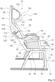
- the seat device includes a backrest unit 26.
- the backrest unit 26 is provided for the purpose that a passenger sitting on the passenger seat 10 can lean on his back.
- the backrest unit 26 is attached to the rear end of the seat bottom unit 14 .
- the backrest unit 26 delimits the seating area 16 to the rear.
- the backrest unit 26 is rigidly connected to the seat bottom unit 14 . In principle, it is also conceivable that the backrest unit 26 and the seat bottom unit 14 are pivotably connected to one another via kinematics.
- the backrest unit 26 includes a rigid section 90.
- the rigid section 90 is designed as a lower section of the backrest unit 26.
- the lower rigid portion 90 faces the seat bottom unit 14 .
- the lower partial area 90 of the backrest unit 26 forms a first base body 28 of the backrest unit 26 .
- the base body 28 of the backrest unit 26 partially forms a supporting structure of the backrest unit 26 .
- the first base body 28 of the backrest unit 26 is formed in one piece with the base body 18 of the seat base unit 14 .
- the base body 28 of the lower rigid partial area 90 is formed by the thin-walled rear wall 66 , the thin-walled front wall 68 and the stiffening element 70 arranged between the thin-walled rear wall 66 and the thin-walled front wall 68 .
- the thin-walled front wall 68 extends upwards from the seat base unit 14 in a region of the lower partial region 90 of the backrest unit 26 on a front side of the backrest unit 26 .
- the thin-walled rear wall 66 points upwards from the seat bottom unit 14 in a region of the lower partial region 90 of the backrest unit 26 on a rear side of the backrest unit 26 .
- the transitions between the thin-walled front wall 68 and the thin-walled rear wall 66 between the backrest unit 26 and the seat bottom unit 14 are each formed by radii. Due to the one-piece design of the base body 18, 28 of the seat base unit 14 and the lower portion 90 of the backrest unit 26, the seat base unit 14 and the lower portion 90 of the backrest unit 26 are rigidly connected to each other.
- the seat bottom unit 14 and the lower portion 90 of the backrest unit 26 have a fixed, unchangeable angle to one another.
- a seat angle between the backrest unit 26 and the seat base unit 14 in a basic position is defined by the angle that the seat base unit 14 and the lower partial area 90 of the backrest unit 26 have to one another.
- the seat angle between the backrest unit 26 and the seat bottom unit 14 is 130 degrees.
- the base body 28, which forms the lower portion 90 of the backrest unit 26 from the base body 18 of the seat bottom unit 14, is formed separately. It would be conceivable that the base body 28 of the backrest unit 26 is also constructed in a sandwich construction and consists of a thin-walled front wall, a thin-walled rear wall and a stiffening element. The one formed separately from the base body 18 of the seat bottom unit 14 The first base body 28 of the backrest unit 26 would be firmly and rigidly connected to the base body 18 of the seat bottom unit 14 during assembly by means of a type of connection that appears sensible to a person skilled in the art, for example a screw connection.
- the base bodies 18, 28 In such a configuration of the base bodies 18, 28, a pivotable connection between the base bodies 18, 28 would also be conceivable.
- the base body 28 it is also conceivable for the base body 28 to be formed from a different material that the person skilled in the art considers appropriate, such as a metal, for example.
- the backrest unit 26 has an upper portion 92 .
- the upper section 92 is designed to be pivotable relative to the lower section 90 .
- the backrest unit 26 has a second base body 94 which forms the upper partial area 92 .
- the base body 94 is essentially formed from a fiber composite material.
- the base body 94 is designed in a sandwich construction.
- the base body 94 has a thin-walled rear wall 96, a thin-walled front wall 98 and a stiffening element, not shown in detail, enclosed therein.
- a structure of the base body 94 corresponds approximately to that of the base body 18 of the seat bottom unit 14. In principle, it is also conceivable for the base body 94 to be formed from another material that the person skilled in the art considers appropriate, such as a metal.
- the backrest unit 26 includes a bearing unit 100.
- the bearing unit 100 allows the lower section 90 and the upper section 92 to be pivoted relative to one another.
- the bearing unit 100 pivotally connects the first base body 28 of the backrest unit 26, which forms the lower section 90, to the second base body 94 of the backrest unit 26.
- the bearing unit 100 has a maximum pivoting range of approximately 35 degrees, by which the lower section 90 and the upper portion 92 are pivotable to each other. In principle, a swivel range of 40 to 50 degrees is also possible.
- the bearing unit 100 which supports the rigid lower section 92 with the upper pivotable section 92 has a pivot axis 102 .
- the pivot axis 102 is offset forward in the seat direction 80 with respect to a rear end of the backrest unit 26 .
- the pivot axis 102 is arranged in front of the thin-walled rear wall 96 or the thin-walled rear wall 66, as seen in the seat direction 80.
- FIG. The pivot axis 102 is, viewed in the seat direction 80, arranged in front of the thin-walled front wall 68, 98 and the thin-walled rear wall 66, 96, respectively.
- the first base body 28 and the second base body 94 each form an elevation 104, 106 extending in the seat direction 80 in their outer regions on sides facing one another.
- the bearing mounts are connected to one another via a bearing element 108 .
- the bearing element 108 is designed as a bearing bolt. In principle, it is also conceivable that the bearing element 108 is designed as another bearing element that appears sensible to a person skilled in the art.
- the base body 28 and the base body 94 can be pivoted relative to one another via the bearing element 108 .
- the bearing unit 100 has a plurality of stop elements 110, 112 which limit the lower partial area 90 and the upper partial area 92 to their maximum positions in relation to one another.
- a stop element 110 is formed by the base body 94 which forms the upper partial area 92 .
- the stop element 112 is formed by the base body 28 which forms the lower partial area 90 .
- a comfort position which is designed as a basic position
- the two stop elements 110, 112 rest against one another and thereby fix the lower partial area 90 and the upper partial area 92 of the backrest unit 26 to one another.
- the bearing unit 100 has further stop elements, not shown in detail, which contact one another in a TTL position of the backrest unit 26 and thereby fix the lower partial area 90 and the upper partial area 92 of the backrest unit 26 in the TTL position to one another.
- the backrest unit 26 forms a backrest support surface 30 .
- the backrest unit 26 comprises a first upholstery element 32 and a second upholstery element 114.
- the first upholstery element 32 is attached to a front side of the first base body 28 of the backrest unit 26.
- the first upholstery element 32 forms the backrest support surface 30 in the lower partial area 90 of the backrest unit 26 .
- the backrest unit 26 has a plurality of connection elements, not shown in detail, which are correspondingly integrated into the base body 28 and the upholstery element 32 .
- the connection elements are designed as loop and hook tapes.
- connection elements are designed in a different way that appears sensible to the person skilled in the art as positive and/or non-positive locking elements, such as snaps.
- the padding element 32 is made of an elastic material, such as in particular a foamed plastic. In principle, it is also conceivable for the padding element 32 to be formed from another elastic plastic and/or natural material that appears sensible to a person skilled in the art.
- the upholstered element 32 forms the backrest support surface 30 on its front side facing away from the base body 28 .
- the upholstery element 32 has a cover, not shown or designated in detail, which closes the upholstery element 32 on the backrest support surface 30 . The cover can be separated from the upholstery element 32 and can be separated from the upholstery element 32 for cleaning or replacement.
- the second pad member 114 is attached to a front side of the second base body 94 of the backrest unit 26 .
- the second upholstered element 114 forms the backrest support surface 30 in the upper partial area 92 of the backrest unit 26 .
- the backrest unit 26 has a plurality of connection elements, not shown in detail, which are correspondingly integrated into the base body 94 and the upholstery element 114 .
- the connection elements are designed as loop and hook tapes.
- the backrest support surface 30 has a lower area which is formed by the upholstery element 32 .
- the lower area of the backrest support surface 30 is arranged on a side of the backrest unit 26 facing the seat bottom unit 14 .
- the lower area of the backrest support surface 30 faces the cabin floor in an assembled state.
- the backrest support surface 30 has an upper area which is formed by the upholstery element 114 .
- the upper area of the backrest support surface 30 is arranged on a side of the backrest unit 26 facing away from the seat bottom unit 14 .
- the upper area of the backrest support surface 30 faces away from the cabin floor in an assembled state.
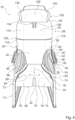
- the backrest support surface 30 has a taper at the lower end.
- the backrest support surface 30 is narrower in the lower area than in the upper area.
- the lower area of the backrest support surface 30 has a width that is more than 50% smaller than a width of the backrest support surface 30 in the upper area.
- a transition between the upper, wide area of the backrest support surface 30 and the lower, narrow area of the backrest support surface 30 is formed by a radius.
- the rejuvenation of Seat back support surface 30 increases in the lower region from a transition from the upper region to a lower end of the seat back support surface 30 .
- the lower area, which forms the tapering of the backrest support surface 30, is wider at an upper end facing the upper area than at the lower end facing away from the upper area.
- the narrowing it is also conceivable for the narrowing to have the same width over its entire length.
- the backrest unit 26 forms contact elements 116, 118 which extend laterally forwards.
- the contact elements 116, 118 are provided so that a passenger sitting on the passenger seat 10 can lean against the contact elements 116, 118 laterally.
- the contact elements 116, 118 each extend from a lower area of the upper partial area 92 of the backrest unit 26 to an upper area of the lower partial area 90 of the backrest unit 26.
- the contact elements 116, 118 rise steadily from the backrest support surface 30 in a radius , until they have their maximum extent approximately in the area of the bearing unit 100 and then steadily decrease in a radius down to the backrest support surface 30 .
- Upper sections of the contact elements 116, 118 are formed by the cushion element 114, which is arranged on the base body 94 of the upper section 92 of the backrest unit 26.
- Lower partial areas of the contact elements 116, 118 are formed by the cushion element 32, which is arranged on the base body 28 of the lower partial area 90 of the backrest unit 26.
- the backrest unit 26 has a headrest 126 .
- the headrest 126 is arranged at an upper end of the upper section 92 of the backrest unit 26 .
- the headrest 126 includes a headrest element 128.
- the headrest element 128 is designed as a padded element.
- the headrest element 128 forms a forward-projecting support element 130, 132 at each of its two lateral ends, which in each case provides a lateral support surface for a passenger's head.
- a passenger can comfortably support his head on the side of the headrest 126, as a result of which the headrest 126 is particularly well suited for side sleepers.
- the supporting elements 130, 132 can be adjusted at an angle to the headrest element 128.
- the height of the headrest 126 in relation to the backrest unit 26 can be adjusted.
- the headrest 126 comprises a linear guide 134.
- the height of the headrest element 128 can be adjusted in relation to the backrest unit 26 via the linear guide 134 .
- the linear guide 134 has a guide rail 136 firmly connected to the backrest unit 26 .
- the headrest element 128 comprises a guide element which is designed to correspond to the guide rail 136 and is not shown in detail, which is guided in the guide rail 136 .
- a movement of the guide element to the guide rail 136 is designed to be self-locking.
- a force must be exerted along a displacement axis of the guide rail 136 that is greater than a force that is exerted on the head support element 128 during operation by a head resting on the head support element 128. This prevents the headrest element 128 from being inadvertently adjusted.
- the headrest 126 it is also conceivable for the headrest 126 to have a locking mechanism which locks the headrest 126 in the various positions, with a passenger having to unlock it manually, for example by means of a push button.
- the seat device also includes a first armrest unit 34.
- the seat device also includes a second armrest unit 36.
- the two armrest units 34, 36 are intended to delimit the seat area 16 laterally.
- the armrest units 34, 36 delimit the seat area 16 on two opposite sides of the seat base unit 14.
- the armrest units 34, 36 delimit the seat area 16 in a direction orthogonal to a seat direction of the passenger seat 10.
- the armrest units 34, 36 are designed to be equivalent to one another.
- the first armrest unit 34 and the second armrest unit 36 are mirror images. In the following, therefore, only the first armrest unit 34 is described in more detail, it being possible for the description to be transferred to the second armrest unit 36, which is of identical design as a mirror image.
- the armrest unit 34 is intended to provide a support surface 38 for a passenger seated on the passenger seat 10 .
- the support surface 38 is provided so that a passenger can at least partially rest his arm and/or his hand on it.
- the armrest unit 34 comprises a supporting and/or separating element 40.
- the supporting and/or separating element 40 is intended to provide a supporting surface 42 for the passenger. In this case, the supporting and/or separating element 40 forms a lateral supporting surface 42 .
- the support surface 42 is towards the seating area 16 aligned.
- the support surface 42 is aligned essentially orthogonally to the seating surface formed by the seating area 16 .
- the support surface 42 runs essentially orthogonally to the cabin floor.
- the supporting and/or separating element 40 extends forward from the backrest unit 26 at a distance from the seat bottom unit 14 .
- the supporting and/or separating element 40 is connected to the backrest unit 26 at a rear end facing the backrest unit 26 .
- the supporting and/or separating element 40 is rigidly connected to the backrest unit 26 .
- the supporting and/or dividing element 40 and the backrest unit 26 each have correspondingly designed connection areas, not shown in detail, via which the supporting and/or dividing element 40 is rigidly connected to the Backrest unit 26 is connected.
- the supporting and/or separating element 40 is connected to the backrest unit 26 via a screw connection that is not shown in detail.
- the supporting and/or separating element 40 it is also conceivable for the supporting and/or separating element 40 to be firmly connected to the backrest unit 26 via another form-locking, non-positive and/or material connection that appears sensible to the person skilled in the art. In principle, it is also conceivable for the supporting and/or separating element 40 to be pivotably coupled to the backrest unit 26 via kinematics.
- the supporting and/or separating element 40 has an upper edge 44 which forms a contour of the supporting and/or separating element 40 which faces away from the seat bottom unit 14 .
- the upper edge 44 has different heights in different areas of the supporting and/or separating element 40 . As a result, the supporting and/or separating element 40 has different heights in the different areas.
- the supporting and/or separating element 40 has a rear region which faces the backrest unit 26 .
- the supporting and/or separating element 40 has a central region which adjoins a side of the rear region of the supporting and/or separating element 40 which faces away from the backrest unit 26 .
- the supporting and/or separating element 40 has a height that is smaller than a height in the central area of the supporting and/or separating element 40.
- the supporting and/or separating element 40 is in that of the backrest unit 26 facing area flatter to create a clearance for an elbow of the passenger sitting on the seat.
- the upper edge 44 forms a support surface in the rear area, in particular for the elbow of a passenger.
- the supporting and/or separating element 40 has a front area which is on a rear area is arranged opposite side of the central area. In the front area, the supporting and/or separating element 40 again has a lower height than in the middle area. The contour is curved from the rear area over the middle area to the front area. The height of the supporting and/or separating element 40 increases in a transition from the rear area to the front area in an arc, with a maximum height of the supporting and/or separating element 40 being reached shortly after the transition to the middle area. From the maximum height, the height of the supporting and/or separating element 40 steadily decreases in an arc up to the front end of the supporting and/or separating element 40 . The supporting and/or separating element 40 forms approximately the shape of half an arrowhead.
- the armrest unit 34 has a first support element 46 to form the support surface 38 .
- the support element 46 is provided to form the support surface 38, which is aligned essentially parallel to the seat surface, in at least one operating state.
- the support element 46 has a wing shape.
- the support element 46 has a rear region which faces the backrest unit 26 .
- a rear end of the support element 46 is arranged at a distance from the backrest unit 26 in an assembled state.
- the first support element 46 is adjustable between different positions.
- the first support element 46 is pivotable.
- the first support element 46 is pivotably mounted relative to the supporting and/or separating element 40 .
- the first support element 46 can be pivoted between a rest position and a use position.
- the support element 46 In a rest position, the support element 46 is folded onto the supporting and/or separating element 40 . In the rest position of the support element 46, the support surface 38, which forms the support element 46, cannot be used by a passenger for support. A part of the supporting surface 38, which is formed by the supporting element 46, faces the supporting surface 42 of the supporting and/or separating element 40 in the rest position. In the position of use, the support element 46 is folded away from the supporting and/or separating element 40 . An angle between the supporting surface 42 of the supporting and/or separating element 40 and the bearing surface 38 of the first bearing element 46 is approximately 90 degrees in the position of use. In the position of use, the supporting and/or separating element 40 and the supporting element 46 essentially form an L-shape.
- the support element 46 In the rest position, the support element 46 forms a support surface 58 .
- the support surface 58 of the support element 46 is formed by an underside of the support element 46 opposite the support surface 38 .
- the support surface 58 In the position of use, the support surface 58 is oriented downwards and faces the seat bottom unit 14 .
- the supporting surface 58 In the rest position, in which the support element 46 is folded onto the supporting and/or separating element 40 , the supporting surface 58 is directed inwards and faces the seating area 16 .
- a passenger can lean against the support surface 58 .
- the passenger can advantageously position himself comfortably in the passenger seat 10 and support himself laterally on the support surface 58 of the support element 46 .
- the armrest unit 36 has a further support element 48 .
- the additional support element 48 is provided to at least partially form the support surface 38 for the passenger.
- the further bearing element 48 is arranged between the supporting and/or separating element 40 and the first bearing element 46 .
- the additional support element 48 is rigidly connected to the supporting and/or separating element 40 .
- the further support element 48 is formed in one piece with the supporting and/or separating element 40 .
- the additional support element 48 it is also conceivable for the additional support element 48 to be connected to the supporting and/or separating element 40 in a positive, non-positive and/or material connection. It is conceivable, for example, for the support element 48 to be connected to the supporting and/or separating element 40 via a screw connection or an adhesive connection.
- a transition between the support surface 42 formed by the support and/or separating element 40 and the support surface 38 formed by the further support element 48 is formed by a radius.
- the armrest unit 34 has a hinge 50 for the pivotable mounting of the first supporting element 46 relative to the supporting and/or separating element 40 .
- the hinge 50 is arranged between the first support element 46 and the further support element 48 .
- the hinge 50 is partially formed by the first support element 46 and partially by the further support element 48 .
- the first support element 46 has a plurality of through-holes which are arranged at a distance from one another and are separated from one another by recesses.
- the further support element 48 also forms through-holes, which are introduced into molded webs, which correspond to the recesses are formed, which has the first support member 48 between its through holes.
- the webs formed onto the further support element 48 are arranged in the recesses of the first support element 46, as a result of which the through-holes of the first support element 46 and the further support element 48 are aligned.
- the hinge 50 has a pin element which is guided through the through-holes of both bearing elements 46, 48 of the hinge 50 for the pivotable connection of the first bearing element 46 and the further bearing element 48.
- the two support elements 46, 48 can be pivoted relative to one another via the pin element.
- the pin element forms a pivot axis 52 about which the first bearing element 46 can be pivoted relative to the supporting or separating element 40 .
- the pivot axis 52 runs along a main extension of the armrest unit 34.
- the pivot axis 5a runs essentially parallel to the seat direction 80. parallel to the seat direction 80.
- the hinge 50 has a stop element 138, which the first support element 46 in the use position and in the rest position holds.
- the stop element 138 is designed as a stop element that is rigidly connected to the support element 46 . In the position of use, the stop element 138 strikes a stop, not shown in any more detail, below the support element 48, so that the support element 46 is fixed in the position of use.
- the hinge 50 has one or more locking elements that fix the first support element 46 in the use position and in the rest position.
- the first support element 46 is linked to a lower end of the armrest unit 34 by being mounted via the hinge 50 .
- the seat assembly includes a first support member 54.
- the support member 54 spans an area between the seat bottom assembly 14 and the armrest assembly 34.
- the seat assembly includes a second support member 56 forming an area between the seat bottom assembly 14 and the armrest assembly 36.
- the support element 56 is designed as a mirror image of the support element 54 . Since the supporting elements 54, 56 represent essentially identical mirror images of one another, only the first supporting element 54 is described in more detail below. The following description of the first support element 54 can also be used to explain the second support element 56 .
- the support element 54 which spans the area between the seat bottom unit 14 and the armrest unit 34, is provided for the purpose that the passenger sitting on the passenger seat 10 can support his lower back thereon.
- the support element 54 is provided for lateral support of the passenger.
- the support element 54 is arranged in the area between the seat bottom unit 14 , the armrest unit 34 and the backrest unit 26 .
- the support element 54 is designed as a covering element.
- the support element 54 designed as a covering element is stretched between the armrest unit 34 , the seat bottom unit 14 and the backrest unit 26 .
- the supporting element 54 designed as a covering element is formed by a net. In principle, it is also conceivable that the supporting element 54 designed as a covering element is made of fabric or another elastic material, such as leather or a thin plastic element.
- the support member 54 is connected to the armrest unit 34 at an upper end.
- the support member 54 extends over an entire length of the armrest unit 34.
- the support member 54 is attached to a lower side of the support member 48. As shown in FIG. In principle, it is also conceivable that the support element 54 is attached to another component of the armrest unit 34 .
- the support element 54 has a connection area that is not shown in detail.
- the connection area is arranged at the upper end of the support element 54 .
- the connection area has at least one connection element via which the support element 54 can be connected to the armrest unit 34 .
- the connection element is designed as a positive and/or non-positive connection element, for example as a loop and hook strip or as part of a zip fastener.
- the support element 54 is connected to the armrest unit 34 in the connection area via a clamp connection.
- the support element 54 it would also be conceivable for the support element 54 to be connected in its connection area to the armrest unit 34, in particular to the support element 48, via a material connection, such as in particular an adhesive connection.
- the support element 54 is connected to the backrest unit 26 at a rear end.
- the support element 54 has a connection area (not shown) at its rear end. With the connection area, not shown, the support element 54 is connected to the first Main body 28 of the backrest unit 26 connected.
- the connection area has at least one connection element via which the support element 54 can be connected to the first base body 28 of the backrest unit 26 .
- the connection element is designed as a positive and/or non-positive connection element, for example as a loop and hook strip or as part of a zip fastener. In principle, it is also conceivable that the support element 54 is connected to the base body 28 of the backrest unit 26 in the connection area via a clamp connection.
- the support element 54 may be connected to the backrest unit 26 via a piping connection.
- the support element 54 it would also be conceivable for the support element 54 to be connected in its connection area to the base body 28 of the backrest unit 26 via a material connection, such as in particular an adhesive connection.
- the support element 54 connects directly to the taper in the backrest support surface 30 .
- the support member 54 extends inward at a rear end toward the seat bottom unit 14 from an upper point where the support member 54 is connected to the armrest unit 34 .
- the support element 54 merges into the backrest support surface 30 on its side facing the backrest unit 26 .
- the support element 54 is connected to the seat bottom unit 14 at its lower end.
- the support element 54 is connected to the base body 18 of the seat bottom unit 14 .
- the support element 54 includes a connection area.
- the support element 54 is firmly connected to the base body 18 via the connection area.
- the support element 54 is not firmly connected to the base body 18 of the seat base unit 14 via the connection area, but is merely clamped between the base body 18 and the upholstered element 20 .
- the support element 54 it would also be conceivable for the support element 54 to be connected to the base body 18 of the seat bottom unit 14 via a piping connection. In an assembled state, the support element 54 connects directly to the narrowing of the seat bottom unit 14 .
- the support element 54 extends from a front end, which is arranged approximately at the front end of the armrest unit 34 facing away from the backrest unit 26, from the outside in the direction of the backrest unit 26 inwards.
- the support member 54 extends furthest inward. From that At the point where the taper of the backrest support surface 30 and the taper of the seat bottom unit 14 meet, the support element 54 extends outwardly as viewed in the direction of the seat. From the point at which the tapering of the backrest support surface 30 and the tapering of the seat bottom unit 14 meet, the support element 54 extends in the direction of the backrest unit 26, that is to say viewed upwards, also outwards.
- the support element 54 is designed as a covering element.
- the support element 54 designed as a covering element is stretched in the area between the armrest unit 34 , the seat bottom unit 14 and the backrest unit 26 .
- the support element 54 designed as a covering element is made from a flexible material.
- the supporting element 54 designed as a covering element is formed by a textile.
- the support element 54 is formed by a net.
- the support element 54 is formed from a substance or another flexible material. It is conceivable that the support element 54 is formed from a plastic plate, for example.
- the armrest unit 34 has a stiffening element 124 .
- the stiffening member 124 is attached to a front end of the support member 54 .
- the stiffening element 124 is intended to keep the support element 54 in shape in its front area.
- the stiffening element 124 is designed as a web to which the support element 54 is connected.
- the stiffening element 124 connects the armrest unit 34 to the seat bottom unit 14.
- the stiffening element 124 is arranged at the front end of the armrest unit 34 and extends from an underside of the armrest unit 34 downward in the direction of the seat bottom unit 14.
- the stiffening element is at its lower end 124 is firmly connected to the seat bottom unit 14, in particular to the base body 18 of the seat bottom unit 14.
- stiffening element 124 it is also conceivable for the stiffening element 124 to be designed merely as a reinforcement that is introduced into the support element 54 formed by a textile. It would be conceivable, for example, for a web to be sewn into the support element 54 .
- the seat device includes an adjustment unit that is not shown in detail.
- the setting unit has a locking mechanism which can lock the support element 54, which is designed as a covering element, at different lengths.
- the size of the support element 54 stretched between the seat bottom unit 14, the armrest unit 34 and the backrest unit 26 can be adjusted by the locking mechanism.
- the locking mechanism has a clamping element that clamps the support element 54 on one side.
- the support element 54 Depending on how hard or soft the support element 54 is set, a greater or lesser part of the support element 54 in the area between the seat bottom unit 14, the armrest unit 34 and the backrest unit 26 is released.
- the support member 54 is set hard, an excess portion of the support member 54 is located behind the locking mechanism and is unusable by the passenger. As a result, the support element 54 is under more tension and cannot be deflected as far by a passenger. If the support element 54 is set softer, the excess part that was previously clamped behind the clamping element is released and is now also located in the area between the seat bottom unit 14, the armrest unit 34 and the backrest unit 26 Passenger are further deflected.
- the passenger seat 10 with the seat device can be positioned in different seat positions.
- the backrest unit 26 connected to the seat bottom unit 14 is positioned differently in the different seating positions.
- a first seating position, in which the backrest unit 26 or the passenger seat 10 can be positioned, is designed as the comfort position.
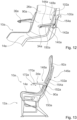
- the comfort position is in the figure 7 shown.
- the comfort position is designed as a basic position optimized for the passenger.
- the basic position is designed as a position for which all parameters of the seat are optimally designed in order to achieve the best possible comfort for a passenger in the comfort position.
- the backrest unit 26 forms a backrest support surface 30 that is essentially planar.
- the backrest support surface 30 has an incline of substantially 135 degrees to the pad plane.
- the lower, rigid section 90 of the backrest unit 26 and the upper, pivotable section 92 are essentially aligned with one another in one plane and are not pivoted with respect to one another (see FIG figure 7 ).
- the upholstered elements 32, 114 form an essentially planar backrest support surface 30. There is essentially no offset in a transition between the cushion element 32 and the cushion element 114 in the comfort position.
- the backrest unit 26, whose sections 90, 92 are essentially aligned with one another in one plane, and the seat floor unit 14 enclose a seat angle of 130 degrees.
- TTL position Another seating position is designed as the TTL position.
- the upper pivotable portion 92 In the TTL position, the upper pivotable portion 92 is erected and oriented substantially perpendicular to the stand plane.
- the TTL position represents a maximum adjustment of the upper section 92 to the lower section 90 of the backrest unit 26.
- the upper section 92 In the TTL position, the upper section 92 is pivoted by essentially 30 degrees to the lower section 90.
- the upper sub-area 92 can be continuously adjusted and locked between the comfort position and the TTL position relative to the lower sub-area 90 .
- the seat device comprises a locking unit that is not shown in detail.
- the locking unit locks the upper sub-area 92 in the various positions relative to the lower sub-area 90.
- the locking unit has a compression spring, for example, which fixes the two sub-areas 90, 92 to one another and uses an actuating element by the operator to adjust the two Sections 90, 92 can be unlocked.
- a locking unit known from the prior art is conceivable here, which is provided for adjusting a backrest unit 26 in relation to the seat base unit 14 .
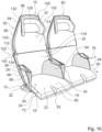
- the figures 9 and 10 each show a part of a layout with several passenger seats 10, 60, 62 with the seat device according to the invention.
- the passenger seats 10, 60, 62 are elevated in the aircraft cabin.
- the passenger seats 10, 60, 62 are arranged in a different way.
- the passenger seats 10, 62 are arranged one behind the other in a longitudinal row 120 of seats.
- the aircraft passenger seats 10, 62 arranged one behind the other in the longitudinal seat row 120 have a pitch spacing of 33 inches.
- a longitudinal row 120 of seats preferably more than 10 passenger seats 10, 62 are arranged one behind the other in the aircraft cabin.
- the backrest unit 26 of the front passenger seat 10 extends over a seat floor unit 122 of the rear passenger seat 62.
- the front passenger seat 10 and the rear passenger seat 62 overlap at least partially.
- an upper partial area 92 of the backrest unit 26 is arranged above the seat bottom unit 122 of the rear passenger seat 62, viewed in a vertical direction.
- An overlap of the backrest unit 26 of the front passenger seat 10 in the comfort position with the seat bottom unit 122 of the rear passenger seat 62 is 3.5 inches.
- an overlap is designed to be larger or smaller.
- the two passenger seats 10, 62 arranged one behind the other do not have any overlap.
- the backrest unit 26 of the front passenger seat 10 does not overlap with the rear passenger seat 62.
- a passenger can advantageously easily get into his passenger seat 62.
- All aircraft passenger seats 10, 62 arranged in a longitudinal row 120 of seats are arranged at the same distance from one another.
- the Figures 12 and 13 show a seat device according to the invention in a second embodiment.
- the seat device is designed as an aircraft passenger seat device.
- the seat device is designed as part of a seat, in particular as part of an aircraft passenger seat 10a.
- the seat device has a stand unit 12a.
- the Stand unit 12a is provided to stand the passenger seat 10a on a cabin floor.
- the seat device includes a seat bottom unit 14a.
- the seat bottom unit 14a is intended to provide a seating area 16a on which a passenger can sit, in particular during a flight.
- the seating area 16a forms a seat surface on which the passenger sits.
- the seat bottom unit 14a is connected to the stand unit 12a.
- the seat bottom unit 14a is rigidly connected to the stand unit 12a.
- the seat bottom unit 14a includes a base body 18a.
- the base body 18a of the seat bottom unit 14a is connected to the stand unit 12a.
- the base body 18a is formed at least partially from a fiber composite material.
- the base body 18a it is also conceivable for the base body 18a to be formed from a metal, such as magnesium in particular.
- the base body 18a is particularly preferably formed from a magnesium die-cast.
- the seat device includes a backrest unit 26a.
- the backrest unit 26a is provided so that a passenger sitting on the passenger seat 10a can lean on his back.
- the backrest unit 26a is attached to the rear end of the seat bottom unit 14a.
- the backrest unit 26a delimits the seating area 16a to the rear.
- the backrest unit 26a is rigidly connected to the seat bottom unit 14a.
- the backrest unit 26a includes a rigid portion 90a.
- the rigid portion 90a is formed as a lower portion of the backrest unit 26a.
- the lower rigid portion 90a faces the seat bottom unit 14a.
- the lower partial area 90a of the backrest unit 26a forms a first base body 28a of the backrest unit 26a.
- the base body 28a of the backrest unit 26a partially forms a supporting structure of the backrest unit 26a.
- the first base body 28a of the backrest unit 26a is formed in one piece with the base body 18a of the seat bottom unit 14a.
- the base body 28a of the lower rigid partial area 90a is formed by a thin-walled rear wall 66a, a thin-walled front wall 68a and a stiffening element 70a arranged between the thin-walled rear wall 66a and the thin-walled front wall 68a.
- the base body 28a of the lower partial area 90a can in principle also be embodied as a frame with a covering. It is conceivable that the frame, which forms part of the base body 28a, is formed from a metal or a fiber composite material. A fabric covering is connected under tension to the frame and forms a support surface for the passenger.
- the backrest unit 26a has an upper portion 92a.
- the upper portion 92a is pivotable to the lower portion 90a.
- the backrest unit 26a has a second base body 94a, which forms the upper partial area 92a.
- the base body 94a is essentially formed from a fiber composite material.
- the base body 94a of the upper partial area 92a can in principle also be embodied as a frame with a covering. It is conceivable that the frame, which forms part of the base body 94a, is formed from a metal or a fiber composite material. A fabric covering is connected under tension to the frame and forms a support surface for the passenger.
- the backrest unit 26a includes a bearing unit 100a.
- the lower partial area 90a and the upper partial area 92a can be pivoted relative to one another via the bearing unit 100a.
- the bearing unit 100a pivotally connects the first base body 28a of the backrest unit 26a, which forms the lower partial area 90a, to the second base body 94a of the backrest unit 26a.
- the bearing unit 100a has a pivot axis 102a about which the upper portion 92a can be pivoted relative to the lower portion 90a.
- the bearing unit 100a further includes a spring element that is not shown in detail.
- the spring element is intended to exert a force on the upper partial area 92a so that it is pressed in the direction of the TTL position of the passenger seat 10a. As a result, a passenger experiences resistance when adjusting to the TTL position and can thus comfortably reach the TTL position. When adjusting from the TTL position, the spring element provides an assisting force.
- the seat assembly further includes a first armrest unit 34a.
- the seat device further includes a second armrest unit 36a.
- the two armrest units 34a, 36a are intended to delimit the seat area 16a laterally.
- the armrest units 34a, 36a delimit the seat area 16a on two opposite sides of the seat bottom unit 14a.
- the armrest units 34a, 36a each have a base body 140a.
- the base body 140a of the armrest units 34a, 36a each has a bearing unit 142a.
- the base bodies 142a of the armrest units 34a, 36a are arranged with the lower partial area 90a of the backrest unit 26a by means of the bearing unit 142a.
- the armrest units 34a, 36a can be pivoted to the backrest unit 26a via the bearing unit 142a.
- the armrest units 34a, 36a are between a use position, in which they are aligned essentially parallel to the seat bottom unit 14a, and a stowed position, in which they are aligned substantially parallel to the lower portion 90a of the backrest unit 26a, adjustable.
- the armrest units 34a, 36a each have a comfort element 144a.
- the comfort element 144a is in each case arranged on an upper side of the base body 140a of the corresponding armrest unit 34a, 36a.
- the comfort element 144a is firmly connected to the respective base body 140a.
- the comfort element 144a is made from a soft plastic and forms a support surface for the passenger. In principle, it is also conceivable that the comfort element 144a is formed at least partially or completely from a silicone. It is also conceivable that the comfort element 144a has a coating.
- the backrest unit 26a has a locking unit 146a, which is provided to lock the bearing unit 100a, by means of which the backrest unit 26a can be adjusted, in different positions.
- a locked state of the locking unit 146a the lower partial area 90a and the upper partial area 92a of the backrest unit 26a are fixed to one another.
- the lower partial area 90a and the upper partial area 92a of the backrest unit 26a cannot be pivoted relative to one another when the locking unit 146a is in the locked state.
- the locking unit 146a has latching elements that are not shown in detail.
- the seat device has an actuating unit 148a for actuating the locking unit 146a.
- the actuating unit 148a is arranged at least partially in the armrest unit 34a.
- the actuating unit 148a has a linkage 150a, via which the locking unit 146a can be actuated.
- the linkage 150a is mounted in an axially displaceable manner in the base body 140a of the armrest unit 34a.
- the actuating unit 148a has an actuating lever 152a, which is mounted rotatably in the backrest unit 26a and is provided for unlocking the locking unit 146a in an actuated state.
- the actuating unit 148a has a spring element 154a.
- the spring element 154a is provided to exert a force on the actuating lever 152a, which moves it into a position in which the actuating lever 152a locks the locking unit.
- the spring element 154a is designed as a leaf spring. In principle, it is also conceivable that the spring element 154a can be used in a different manner that is reasonable for a person skilled in the art Appearing spring is formed, such as a spiral spring.
- the actuation unit 148a has an operating element 170a, via which a passenger can operate the actuation unit 148a.
- the operating element 170a is attached to an underside of the armrest unit 34a.
- the operating element 170a is designed as a lever that can be pushed by a passenger.
- the operating element 170a can be embodied, for example, as a rotary knob, a rocker arm or another operating element that appears useful to a person skilled in the art.
- a passenger can use the operating element 170a to move the linkage 150a axially along a displacement axis 172a and thereby deflect the actuating lever 152a against the spring force of the spring element 154a and thus unlock the locking unit 146a.
- the passenger can then pivot this to the lower partial area 90a by applying a force to the upper partial area 92a of the backrest unit 26a. If the passenger then lets go of the operating element again, the spring element 154a presses the actuating lever 152a back into its locking position and the locking unit 146a is locked again.
- the entire armrest unit 34a or at least the main body 140a of the armrest unit 34a forms the linkage and is pushed axially as a whole by a passenger to unlock the locking unit 146a.
- the seat assembly includes a table unit 156a.
- the table unit 156a is intended to be arranged on a rear side of the backrest unit 26a.
- the table unit 156a is arranged on the lower partial area 90a of the backrest unit 26a.
- the table unit 156a is pivotally attached to the rear of the lower portion 90a of the backrest unit 26a.
- the table unit 156a has a base body 158a, which forms a table surface 160a of the table unit 156a.
- the table unit 156a has a bearing unit 162a.
- the bearing unit 162a is arranged at a lower end of the main body 158a of the table unit 156a.
- the bearing unit 162a includes two bearing levers 164a, 166a.
- a bearing lever 164a, 166a is arranged on one side of the base body 158a on the underside.
- the bearing levers 164a, 166a extend approximately 100 degrees away from the table surface 160a of the base body 140a.
- the bearing levers 164a, 166a have a slightly curved extension.
- the bearing levers 164a, 166a have an extent of less than 15 cm.
- the bearing levers 164a, 166a particularly preferably have an extent of less than 10 cm.
- the bearing levers 164a, 166a have an extension of 6 cm.
- the bearing levers 164a, 166a are each pivotally connected to the backrest unit 26a via a pivot bearing at an end remote from the base body 158a.
- the short bearing levers 164a, 166a for connecting the table unit 156a make it particularly advantageous to provide legroom for a passenger, since in particular long bearing levers extending downward for the table unit are eliminated. Furthermore, an advantageous weight saving can be achieved by the short bearing levers 164a, 166a.
- the lower partial area 90a of the backrest unit 26a forms a stop element 168a for each bearing lever 164a, 166a, on which the corresponding bearing lever 164a, 166a strikes when the table unit 156a is in a folded-out state.
Landscapes
- Engineering & Computer Science (AREA)
- Aviation & Aerospace Engineering (AREA)
- Transportation (AREA)
- Mechanical Engineering (AREA)
- Seats For Vehicles (AREA)
Description
- Die Erfindung betrifft eine Sitzvorrichtung nach dem Oberbegriff des Patentanspruchs 1. Es ist bereits eine Sitzvorrichtung, insbesondere eine Fluggastsitzvorrichtung, mit wenigstens einer Sitzbodeneinheit und einer mit der Sitzbodeneinheit verbundenen Rückenlehneneinheit, wobei zumindest die Rückenlehneneinheit in einer Komfortposition und einer weiteren Sitzposition positionierbar ist, vorgeschlagen worden.
- Die Aufgabe der Erfindung besteht insbesondere darin, eine gattungsgemäße Vorrichtung mit verbesserten Eigenschaften hinsichtlich eines Passagierkomforts bereitzustellen. Die Aufgabe wird erfindungsgemäß durch die Merkmale des Patentanspruchs 1 gelöst, während vorteilhafte Ausgestaltungen und Weiterbildungen der Erfindung den Unteransprüchen entnommen werden können.
- Die Erfindung geht aus von einer Sitzvorrichtung, insbesondere einer Fluggastsitzvorrichtung, mit den Merkmalen des Anspruchs 1.
- Es wird vorgeschlagen, dass die Komfortposition als eine für einen Passagierkomfort optimierte Grundposition ausgebildet ist. Unter einer "Sitzvorrichtung" soll dabei insbesondere eine Vorrichtung verstanden werden, die wenigstens einen Teil oder einen gesamten Sitz, wie insbesondere einen Fluggastsitz, ausbildet. Dabei bildet die Sitzvorrichtung insbesondere einen Fluggastsitz aus, der als ein Economy-Class-Sitz oder ein Premium-Economy-Class-Sitz ausgebildet ist, der insbesondere für Mittel- und/oder Langstreckenflüge vorgesehen ist. Die Sitzvorrichtung bildet dabei vorzugsweise insbesondere einen Fluggastsitz mit einer einem Passagier zur Verfügung stehenden Grundfläche von mehr als 0,5 qm aus. Unter einem "Fluggastsitz" soll dabei insbesondere ein Sitz verstanden werden, der in einer Flugzeugkabine eines Flugzeugs aufgeständert ist. Dabei ist der Fluggastsitz vorzugsweise als Teil einer von mehreren nebeneinander angeordneten Fluggastsitzen ausgebildet. Der Fluggastsitz umfasst dabei insbesondere wenigstens eine Sitzbodeneinheit, die einen Sitzbereich für einen Passagier ausbildet, eine Rückenlehneneinheit, die eine Rückenlehnenauflagefläche bereitstellt, an der sich ein auf dem Fluggastsitz sitzender Passagier mit seinem Rücken abstützen kann, und wenigstens eine Armlehneneinheit, auf der der Passagier einen Arm zumindest teilweise ablegen kann. Unter einer "Sitzbodeneinheit" soll dabei insbesondere eine Einheit verstanden werden, die den Sitzbereich für einen Passagier ausbildet, wobei die Sitzbodeneinheit dabei vorzugsweise von einem Grundkörper und einer auf dem Grundkörper angebrachten Polstereinheit gebildet ist. Unter einem "Sitzbereich" soll dabei insbesondere ein Bereich des Fluggastsitzes verstanden werden, der dazu vorgesehen ist, dass ein Passagier, insbesondere während eines Flugs, darauf sitzt. Der Sitzbereich ist dabei von der Sitzbodeneinheit ausgebildet, die vorzugsweise wenigstens einen Grundkörper und ein auf dem Grundkörper angebrachtes Polsterelement umfasst, welches den Sitzbereich ausbildet. Unter einer "Rückenlehneneinheit" soll dabei insbesondere eine Einheit des Fluggastsitzes verstanden werden, die eine Rückenlehnenauflagefläche ausbildet, an der ein auf dem Fluggastsitz sitzender Passagier seinen Rücken anlehnen kann. Dabei umfasst die Rückenlehneneinheit vorzugsweise zumindest einen Grundkörper und eine Polstereinheit, welche die Rückenlehnenauflagefläche ausbildet. Die Rückenlehneneinheit ist dabei an einem hinteren Ende der Sitzbodeneinheit angeordnet und erstreckt sich von der Sitzbodeneinheit nach oben, von einer Aufständereinheit weg. Unter einer "Komfortposition" soll dabei insbesondere eine Position der Sitzvorrichtung verstanden werden, in der eine Rückenlehneneinheit der Sitzvorrichtung eine aus einer TTL-Position nach hinten verschwenkte Neigung aufweist, die einem Passagier eine vorteilhaft komfortable, nicht aufrechte Sitzposition ermöglicht. Unter einer "weiteren Sitzposition" soll dabei insbesondere eine Sitzposition verstanden werden, in der insbesondere die Rückenlehneneinheit eine andere Neigung zu einem Kabinenboden aufweist als in der Komfortposition. Dabei ist eine weitere Sitzposition beispielsweise als TTL-Position ausgebildet. Unter einer "TTL-Position" soll dabei insbesondere eine aufrechte Position des Fluggastsitzes verstanden werden, die aus Sicherheitsgründen, insbesondere in einer Startphase, in einer Landephase und während Turbulenzen, eingenommen werden muss. Dabei stehen in der TTL-Position eine Rückenlehneneinheit des Fluggastsitzes und der Sitzboden im Wesentlichen senkrecht aufeinander, vorzugsweise in einem Winkel von zwischen 90 Grad und 105 Grad. Die TTL-Position bildet dabei eine erste Endposition aus, in die der Flugzeugsitz maximal verstellbar ist. Unter einer "Grundposition" soll dabei insbesondere eine Position verstanden werden, für die ein Sitz, insbesondere ein Fluggastsitz, ausgelegt und konstruiert ist. In der Grundposition bildet die Rückenlehneneinheit vorzugsweise eine im Wesentlichen ebene durchgehende Fläche aus. Unter "vorgesehen" soll insbesondere speziell ausgelegt und/oder ausgestattet verstanden werden. Darunter, dass ein Objekt zu einer bestimmten Funktion vorgesehen ist, soll insbesondere verstanden werden, dass das Objekt diese bestimmte Funktion in zumindest einem Anwendungs- und/oder Betriebszustand erfüllt und/oder ausführt. Durch eine erfindungsgemäße Ausgestaltung kann ein besonders komfortabler Sitz für einen Passagier bereitgestellt werden, insbesondere kann ein Schlafkomfort erhöht und ein Seitenschlaf ermöglicht werden.
- Weiter wird vorgeschlagen, dass die Rückenlehneneinheit einen starren Teilbereich aufweist, der starr mit der Sitzbodeneinheit gekoppelt ist. Unter einem "starren Teilbereich" soll dabei insbesondere ein Teilbereich verstanden werden, der in sich im Wesentlichen nicht elastisch verformbar ist. Unter "starr gekoppelt" soll dabei insbesondere verstanden werden, dass die beiden miteinander gekoppelten Elemente, wie insbesondere der starre Teilbereich der Rückenlehneneinheit und die Sitzbodeneinheit, eine feste zerstörungsfrei unveränderliche Ausrichtung zueinander aufweisen. Dadurch können die Rückenlehneneinheit und die Sitzbodeneinheit besonders vorteilhaft zumindest teilweise gemeinsam ausgebildet werden, wodurch eine besonders vorteilhafte Ergonomie für einen Passagier erzielt werden kann.
- Es wird weiter vorgeschlagen, dass die Rückenlehneneinheit einen oberen Teilbereich aufweist, der schwenkbar zu dem unteren starren Teilbereich ausgebildet ist. Unter einem "oberen Teilbereich" soll dabei insbesondere ein Teilbereich der Rückenlehneneinheit verstanden werden, der einen von einer Aufständereinheit abgewandten Teil der Rückenlehneneinheit ausbildet. Dabei sind der obere Teilbereich und der untere starre Teilbereich vorzugsweise als separate Bauteile ausgebildet. Unter "schwenkbar" soll dabei insbesondere verstanden werden, dass eine Ausrichtung des oberen Teilbereichs und des unteren Teilbereichs durch eine Rotation zueinander um eine gemeinsame Schwenkachse verstellbar ist. Dadurch kann eine besonders vorteilhafte Rückenlehneneinheit bereitgestellt werden, die insbesondere in einer Komfortposition besonders komfortabel für einen Passagier ist und weiterhin in eine notwendige TTL-Position verfahrbar ist.
- Ferner wird vorgeschlagen, dass die Sitzvorrichtung wenigstens eine Lagereinheit, die den starren unteren Teilbereich mit dem oberen schwenkbaren Teilbereich lagert, und eine Schwenkachse ausbildet, die im Bezug auf ein hinteres Ende der Rückenlehneneinheit in Sitzrichtung nach vorne versetzt ist. Unter einer "Lagereinheit" soll dabei insbesondere eine Gleit- und/oder Rolllagerung verstanden werden, über die zwei über die Lagereinheit miteinander verbundene Elemente, wie insbesondere der untere Teilbereich und der obere Teilbereich, zueinander verschwenkt werden können. Unter "nach vorne versetzt" soll dabei insbesondere verstanden werden, dass die Schwenkachse nicht an einem in Sitzrichtung gesehenen hinteren Ende der Rückenlehneneinheit angeordnet ist, sondern in Sitzrichtung nach vorne verschoben ist. Dadurch kann eine besonders vorteilhafte Verschwenkung des unteren Teilbereichs und des oberen Teilbereichs zueinander erreicht werden.
- Weiter wird vorgeschlagen, dass die Sitzvorrichtung wenigstens ein seitlich angeordnetes, sich von der Rückenlehneneinheit in einem Bereich der Lagereinheit nach vorne erstreckendes Anlageelement aufweist. Unter einem "Anlageelement" soll dabei ein Element verstanden werden an dem sich ein Passagier mit einem Teil seines Körpers abstützen kann. Dabei weist die Sitzvorrichtung vorzugsweise auf beiden Seiten der Rückenlehneneinheit jeweils ein Anlageelement auf. Dadurch kann die Rückenlehneneinheit besonders vorteilhaft komfortabel ausgestaltet werden.
- Zudem wird vorgeschlagen, dass die Rückenlehneneinheit und die Sitzbodeneinheit in der Grundposition einen Sitzwinkel von mindestens 120 Grad aufweisen. Unter einem "Sitzwinkel" soll dabei insbesondere ein Winkel verstanden werden, den die Rückenlehneneinheit und die Sitzbodeneinheit in einem montierten Zustand zueinander aufweisen. Dadurch kann eine besonders komfortable und ergonomische Sitzposition erreicht werden. Unter "mindestens 120 Grad" soll dabei insbesondere verstanden werden, dass der Sitzwinkel zwischen der Rückenlehneneinheit und der Sitzbodeneinheit wenigstens 120 Grad, vorzugsweise mehr als 125 Grad und in einer besonders vorteilhaften Ausgestaltung mehr als 130 Grad aufweist.
- Weiterhin wird vorgeschlagen, dass die Rückenlehneneinheit in der Grundposition eine Neigung von wenigstens 120 Grad zu einer Aufständerebene aufweist. Unter einer "Aufständerebene" soll dabei insbesondere eine Ebene verstanden werden, auf der der Fluggastsitz mit seiner Aufständereinheit aufgeständert ist. Dabei wird die Aufständerebene von einem Kabinenboden des Flugzeuges gebildet, in dem der Fluggastsitz angebracht ist. Unter einer "Neigung von wenigstens 120 Grad" soll dabei verstanden werden, dass ein Winkel zwischen der Aufständerebene und der Rückenlehneneinheit wenigstens 120 Grad, vorzugsweise 125 Grad und in einer besonders vorteilhaften Ausgestaltung 130 Grad beträgt. Dadurch kann die Rückenlehneneinheit in der Grundposition besonders vorteilhaft ausgerichtet werden.
- Ferner wird vorgeschlagen, dass der Sitzbereich der Sitzbodeneinheit einen Grundkörper aufweist, der zumindest in einem vorderen Bereich zumindest zwei in einer Querrichtung voneinander getrennte Teilbereiche ausbildet, die in einer Höhe zueinander beweglich sind. Unter einem "Grundkörper" soll dabei insbesondere ein Element verstanden werden, welches Teil einer tragenden Struktur ist und dazu vorgesehen ist, in die Sitzbodeneinheit eingeleitete Kräfte weiterzuleiten. Unter "voneinander getrennten Teilbereichen" sollen dabei insbesondere zwei Bereiche verstanden werden, die insbesondere räumlich voneinander getrennt sind, wobei zwischen den beiden Teilbereichen dabei vorzugsweise eine Lücke angeordnet ist. Grundsätzlich ist es auch denkbar, dass ein Bereich zwischen den beiden voneinander getrennten Teilbereichen durch ein Material gebildet ist, das insbesondere elastische Eigenschaften aufweist, sodass dieses Material eine Bewegung der Teilbereiche zueinander nur unwesentlich einschränkt. Dadurch kann eine besonders vorteilhafte Sitzbodeneinheit bereitgestellt werden.
- Es wird weiter vorgeschlagen, dass der Grundkörper zumindest in seinem vorderen Bereich zumindest einen Schlitz ausbildet, der die zumindest zwei Teilbereiche voneinander abtrennt. Dadurch können die Teilbereiche besonders einfach ausgebildet werden.
- Weiterhin wird vorgeschlagen, dass die Sitzvorrichtung wenigstens eine Armlehneneinheit aufweist, die den Sitzbereich seitlich begrenzt. Unter einer "Armlehneneinheit" soll dabei insbesondere eine Einheit verstanden werden, die einen Teil oder vorzugsweise eine komplette Armlehne für einen Sitz, insbesondere einen Fluggastsitz, ausbildet. Die Armlehneneinheit bildet dabei wenigstens eine Auflagefläche aus, auf der ein auf dem Fluggastsitz sitzender Passagier seinen Arm zumindest teilweise ablegen kann. Zur Ausbildung der wenigstens einen Auflagefläche weist die Armlehneneinheit dabei wenigstens ein Auflageelement auf. Dadurch kann besonders einfach ein Element geschaffen werden, auf dem ein Passagier seinen Arm zumindest teilweise ablegen kann.
- Es wird weiter vorgeschlagen, dass die Armlehneneinheit wenigstens ein im Wesentlichen senkrecht zur Sitzbodeneinheit ausgerichtetes Abstütz- und/oder Abtrennelement und wenigstens ein damit schwenkbar verbundenes Auflageelement aufweist. Unter einem "Auflageelement" soll dabei insbesondere ein Element verstanden werden, das vorzugsweise aus einem elastischen formstabilen Material gebildet ist und wenigstens eine Fläche aufweist, die die Auflagefläche direkt oder indirekt ausbildet. Es ist denkbar, dass das Auflageelement die Auflagefläche direkt ausbildet und ein Passagier direkt in Kontakt mit dem Auflageelement kommt oder dass die Armlehneneinheit wenigstens ein Polsterelement umfasst, das das Auflageelement bedeckt und so die Auflagefläche ausbildet, wodurch das Auflageelement die Auflagefläche indirekt ausbildet. Das Auflageelement ist dabei vorzugsweise verstellbar ausgebildet und kann zumindest zwischen einer Ruhestellung und einer Gebrauchsstellung verstellt werden. Dabei ist das Auflageelement vorzugsweise schwenkbar gelagert und kann zwischen der Ruhestellung und der Gebrauchsstellung verschwenkt werden. Grundsätzlich ist es auch denkbar, dass das Auflageelement auf eine andere Weise zwischen den beiden Stellungen verschiebbar ist, beispielsweise über eine Linearführung. Unter einem "Abstütz- und/oder Abtrennelement" soll dabei insbesondere ein Element verstanden werden, das einen Bereich, insbesondere die Auflagefläche der Armlehneneinheit, von einer Auflagefläche eines benachbarten Fluggastsitzes oder von einem weiteren Bereich des Flugzeugs, wie beispielsweise einem Gang, abtrennt und eine Abstützfläche bereitstellt, an der sich ein Passagier zur Seite hin abstützen kann. Unter einer "Abstützfläche des Abstütz- und/oder Abtrennelements" soll dabei insbesondere eine Fläche verstanden werden, die im Wesentlichen senkrecht zu der Auflagefläche des Auflageelements ausgerichtet und dem Sitzbereich des Fluggastsitzes zugewandt ist. Darunter, dass das "Auflageelement schwenkbar ist", soll dabei insbesondere verstanden werden, dass das Auflageelement über eine Lagerung zwischen zumindest zwei Stellungen verschwenkt werden kann. Dabei ist das Auflageelement vorzugsweise zwischen einer Ruhestellung und einer Gebrauchsstellung verschwenkbar. Unter einer "Ruhestellung des Auflageelements" soll dabei insbesondere eine Stellung des Auflageelements verstanden werden, in der die Auflagefläche des Auflageelements für den Passagier zur Auflage seines Armes nicht genutzt werden kann und das Auflageelement möglichst platzsparend an der Sitzvorrichtung angebracht ist. Die Ruhestellung ist als Stellung ausgebildet, in der der Passagier das Auflageelement nicht benötigt und in der das Auflageelement dabei möglichst platzsparend und komfortabel für den Passagier angeordnet ist. Unter einer "Gebrauchsstellung des Auflageelements" soll dabei insbesondere eine Stellung des Auflageelements verstanden werden, in der die Auflagefläche des Auflageelements für den Passagier zur Auflage seines Armes genutzt werden kann und das Auflageelement dabei von dem Abstütz- und/oder Abtrennelement weggeklappt ist. Durch das schwenkbare Auflageelement kann ein Passagier wahlweise seinen Arm auf die Armlehneneinheit auflegen oder das Auflageelement vorteilhaft wegklappen, um den dadurch entstehenden Raum anders zu nutzen.
- Weiter wird vorgeschlagen, dass die Sitzvorrichtung wenigstens ein Abstützelement aufweist, wobei das Abstützelement zumindest einen Bereich zwischen der Sitzbodeneinheit, der Armlehneneinheit und/oder der Rückenlehneneinheit überspannt. Unter einem "Abstützelement" soll dabei insbesondere ein Element verstanden werden, an dem sich ein Passagier mit einem Teil seines Körpers, insbesondere mit einem unteren, seitlichen Rückenbereich, abstützen kann. Dabei ist das Abstützelement von einem Element gebildet, das eine Fläche aufweist, über die eine Kraft in eine tragende Struktur der Sitzvorrichtung eingeleitet werden kann. Dabei kann das Abstützelement von verschiedenen Elementen gebildet sein. Dabei ist es denkbar, dass das Abstützelement von einem Polster, einem Luftkissen, einem elastischen Kunststoff oder einem Bespannungselement, wie insbesondere einem Textil, gebildet ist. Grundsätzlich ist es auch denkbar, dass mehrere nebeneinander ausgeordnete Abstützelemente vorhanden sind, beispielsweise mehrere nebeneinander verlaufende Gummibänder. Vorzugsweise ist das Abstützelement dabei als ein Bespannungselement ausgebildet. Unter einem "Bespannungselement" soll dabei insbesondere ein elastisches Element verstanden werden, das durch Befestigung an mehreren seiner Enden in einem Bereich aufgespannt ist. Dabei ist das Bespannungselement vorzugsweise von einem Textil, wie insbesondere einem Netz, gebildet. Grundsätzlich ist es auch denkbar, dass das Bespannungselement von einem dünnwandigen Kunststoff, einem Faserverbundwerkstoff oder anderen, dem Fachmann als sinnvoll erscheinenden Materialien gebildet ist. Durch das Abstützelement kann vorteilhaft eine seitliche Abstützung bereitgestellt werden, an der sich ein Passagier mit seinem Rücken seitlich abstützen kann und eine besonders komfortable Position auf dem Fluggastsitz einnehmen kann.
- Weiter wird vorgeschlagen, dass das Abstützelement in einer Ruhestellung des Auflageelements an eine Abstützfläche des Auflageelements anschließt. Unter einer "Abstützfläche des Auflageelements" soll dabei insbesondere eine Fläche verstanden werden, an die sich ein auf dem Fluggastsitz sitzender Passagier insbesondere seitlich anlehnen kann. Dabei ist die Abstützfläche insbesondere gepolstert ausgebildet. Die Abstützfläche ist dabei auf einer der Auflagefläche gegenüberliegenden Seite des Auflageelements angeordnet. Die Abstützfläche ist in der angeklappten Stellung dem Sitzbereich zugewandt. Dadurch kann das Auflageelement in einer Ruhestellung vorteilhaft genutzt werden und so kann ein besonders komfortabler Fluggastsitz bereitgestellt werden.
- Ferner wird vorgeschlagen, dass die Rückenlehneneinheit eine Rückenlehnenauflagefläche ausbildet, die in einem unteren Bereich eine Verjüngung aufweist. Unter einer "Rückenlehnenauflagefläche" soll dabei insbesondere eine Fläche verstanden werden, die dem Passagier zur Verfügung steht, um sich mit seinem Rücken anzulehnen. Unter einem "unteren Bereich" soll dabei insbesondere ein Bereich der Rückenlehneneinheit verstanden werden, der der Sitzbodeneinheit zugewandt ist. Der untere Bereich nimmt dabei in etwa das untere Drittel der Rückenlehnenauflagefläche ein. Unter einer "Verjüngung" soll dabei insbesondere ein Bereich verstanden werden, der über eine definierte Länge unterschiedliche Breiten aufweist und dabei, von einem Startpunkt der Verjüngung aus gesehen, immer schmäler wird. Dadurch kann eine besonders vorteilhafte und komfortable Rückenlehnenauflagefläche erreicht werden.
- Zudem wird ein Layout vorgeschlagen, bei dem wenigstens zwei Fluggastsitze hintereinander angeordnet sind, wobei sich eine Rückenlehneneinheit des vorderen Fluggastsitzes in einer Komfortposition bis über eine Sitzbodeneinheit des hinteren Fluggastsitzes erstreckt. Unter einem "Layout" soll dabei eine Anordnung mehrerer Flugzeuggastsitze in einer Flugzeugkabine verstanden werden. Unter "hintereinander angeordnet" soll dabei insbesondere in einer Reihe hintereinander angeordnet verstanden werden, wobei parallel zu den Sitzrichtungen der Fluggastsitze verlaufende Mittelachsen der hintereinander angeordneten Fluggastsitze koaxial zueinander angeordnet sind. Die hintereinander angeordneten Fluggastsitze sind dabei in dieselbe Richtung ausgerichtet. Dabei sind die Fluggastsitze insbesondere in einem Pitchabstand von 33 Zoll zueinander angeordnet. Der Pitchabstand wird dabei von einem Abstand der Aufständerung von zwei hintereinander angeordneten Fluggastsitzen gebildet. Der Pitchabstand wird dabei beispielsweise durch Messen des Abstands zweier gleicher Bauteile der beiden hintereinander angeordneten Sitze gemessen, beispielsweise durch Messen eines Abstands zwischen einer Vorderkante der Sitzbodeneinheit des vorderen Fluggastsitzes bis zu einer Vorderkante der Sitzbodeneinheit des hinteren Fluggastsitzes. Dabei wird parallel zu der Sitzrichtung der Fluggastsitze, vorzugsweise parallel zu einer Flugzeugkabinenlängsachse gemessen. Eine Überschneidung der Rückenlehneneinheit des vorderen Fluggastsitzes bis über eine Sitzbodeneinheit des hinteren Fluggastsitzes erfolgt dabei lediglich in der Komfortposition. In einer TTL-Position des vorderen Fluggastsitzes besteht insbesondere keine Überschneidung der Rückenlehneneinheit des vorderen Fluggastsitzes bis über eine Sitzbodeneinheit des hinteren Fluggastsitzes. Dadurch kann eine besonders vorteilhafte und platzsparende Anordnung von Fluggastsitzen in einem Layout erreicht werden.
- Weiterhin wird vorgeschlagen, dass eine Überschneidung der Rückenlehneneinheit des vorderen Fluggastsitzes in einer Komfortposition mit der Sitzbodeneinheit des hinteren Fluggastsitzes zumindest 3,5 Zoll beträgt. Unter "zumindest 3,5 Zoll" soll dabei insbesondere zumindest 3,5 Zoll, vorteilhaft zumindest 4 Zoll und in einer besonders vorteilhaften Ausgestaltung zumindest 5 Zoll mm verstanden werden. Dabei beträgt die Überschneidung, insbesondere bei einem Pitchabstand zwischen den Fluggastsitzen von 33 Zoll, insbesondere zumindest 3,5 Zoll. Die Überschneidung der Rückenlehneneinheit des vorderen Fluggastsitzes mit der Sitzbodeneinheit des hinteren Fluggastsitzes in der Komfortposition beträgt dabei zumindest ein Fünftel, vorzugsweise zumindest ein Viertel einer Länge der Sitzbodeneinheit des hinteren Fluggastsitzes. Dabei ist eine Dadurch kann ein besonders vorteilhaft kompaktes Layout bereitgestellt werden.
- Die erfindungsgemäße Sitzvorrichtung soll hierbei nicht auf die oben beschriebene Anwendung und Ausführungsform beschränkt sein. Insbesondere kann die erfindungsgemäße Sitzvorrichtung zu einer Erfüllung einer hierin beschriebenen Funktionsweise eine von einer hierin genannten Anzahl von einzelnen Elementen, Bauteilen und Einheiten abweichende Anzahl aufweisen.
- Weitere Vorteile ergeben sich aus der folgenden Zeichnungsbeschreibung. In den Zeichnungen sind zwei Ausführungsbeispiele der Erfindung dargestellt. Die Zeichnungen, die Beschreibung und die Ansprüche enthalten zahlreiche Merkmale in Kombination. Der Fachmann wird die Merkmale zweckmäßigerweise auch einzeln betrachten und zu sinnvollen weiteren Kombinationen zusammenfassen.
- Es zeigen:
- Fig. 1
- eine schematische Darstellung eines Fluggastsitzes mit einer erfindungsgemäßen Sitzvorrichtung in einem ersten Ausführungsbeispiel,
- Fig. 2
- eine Detailansicht der Sitzvorrichtung mit einer Armlehneneinheit und einem Abstützelement,
- Fig. 3
- eine weitere Detailansicht der Sitzvorrichtung mit einer Armlehneneinheit und einem Abstützelement,
- Fig. 4
- eine schematische Ansicht des Fluggastsitzes ohne ein Polsterelement einer Sitzbodeneinheit,
- Fig. 5
- eine schematische Seitenansicht der Sitzvorrichtung,
- Fig. 6
- eine schematische Seitenansicht der Sitzvorrichtung in einer als Grundposition ausgebildeten Komfortposition,
- Fig. 7
- eine schematische Seitenansicht der Sitzvorrichtung in einer TTL-Position,
- Fig. 8
- eine schematische Detailansicht einer Lagereinheit der Rückenlehneneinheit,
- Fig. 9
- ein erfindungsgemäßes Layout mit mehreren Fluggastsitzen mit der erfindungsgemäßen Sitzvorrichtung,
- Fig. 10
- eine schematische Darstellung von zwei in einer Sitzreihe nebeneinander angeordneten Fluggastsitzen mit der erfindungsgemäßen Sitzvorrichtung und
- Fig. 11
- eine schematische Schnittansicht der Sitzvorrichtung,
- Fig. 12
- eine schematische Darstellung eines Fluggastsitzes mit einer erfindungsgemäßen Sitzvorrichtung in einem zweiten Ausführungsbeispiel,
- Fig. 13
- eine schematische Darstellung des Fluggastsitzes mit einer angedeuteten Verriegelungseinheit und einer Betätigungseinheit und
- Fig. 14
- eine schematische Darstellung des Fluggastsitzes von hinten mit einer Tischeinheit.
- Die
Figuren 1 bis 11 zeigen eine erfindungsgemäße Sitzvorrichtung in einem ersten Ausführungsbeispiel. Die Sitzvorrichtung ist als eine Fluggastsitzvorrichtung ausgebildet. Die Sitzvorrichtung ist als Teil eines Sitzes, insbesondere als Teil eines Fluggastsitzes 10, ausgebildet. Der Fluggastsitz 10 ist in einem montierten Zustand in einer Passagierkabine eines Flugzeugs angebracht. Die Passagierkabine weist einen Kabinenboden auf, auf dem der Fluggastsitz 10 aufgeständert ist. Der Kabinenboden bildet eine Aufständerebene für den Fluggastsitz 10 aus. In der Passagierkabine sind mehrere Fluggastsitze 10, 60, 62 mit der erfindungsgemäßen Sitzvorrichtung angeordnet. Die Fluggastsitze 10, 60, 62 sind dabei in einem im Folgenden beschriebenen Layout in der Passagierkabine angeordnet. Die Fluggastsitze 10, 60 sind zusammen in einer Sitzreihe 64 nebeneinander angeordnet. Die Sitzreihe 64 ist jeweils von drei nebeneinander angeordneten Fluggastsitzen 10, 60 gebildet, wobei eine in den Zeichnungen nicht näher dargestellt ist. Grundsätzlich wäre es auch denkbar, dass die Sitzreihe 64 eine andere Anzahl an Fluggastsitzen 10, 60 aufweist oder dass die Fluggastsitze 10, 60 als Einzelsitze ausgebildet sind, die nicht in einer Sitzreihe angeordnet sind. Im Folgenden wird lediglich ein Fluggastsitz 10 mit der erfindungsgemäßen, als Fluggastsitzvorrichtung ausgebildeten Sitzvorrichtung beschrieben. Die Sitzvorrichtung weist eine Aufständereinheit 12 auf. Die Aufständereinheit 12 ist dazu vorgesehen, den Fluggastsitz 10 und die weiteren Fluggastsitze 60 derselben Sitzreihe 64 auf dem Kabinenboden aufzuständern. Die Aufständereinheit 12 umfasst mehrere, nicht näher dargestellte Verbindungselemente, die die Aufständereinheit 12 fest mit dem Kabinenboden koppeln. Dabei sind die Verbindungselemente vorzugsweise dazu vorgesehen, formschlüssig in einer Befestigungsschiene des Kabinenbodens angeordnet zu sein und zur festen Anbindung der Sitzreihe 64 in der Befestigungsschiene fixiert zu werden. - Die Sitzvorrichtung umfasst eine Sitzbodeneinheit 14. Die Sitzbodeneinheit 14 ist dazu vorgesehen, einen Sitzbereich 16 bereitzustellen, auf dem ein Passagier, insbesondere während eines Flugs, sitzen kann. Der Sitzbereich 16 bildet eine Sitzfläche aus, auf der der Passagier sitzt. Die Sitzbodeneinheit 14 ist mit der Aufständereinheit 12 verbunden. Die Sitzbodeneinheit 14 ist starr mit der Aufständereinheit 12 verbunden. Grundsätzlich ist es auch denkbar, dass die Sitzbodeneinheit 14 über eine Kinematik verschwenkbar mit der Aufständereinheit 12 verbunden ist. Die Sitzbodeneinheit 14 umfasst einen Grundkörper 18. Der Grundkörper 18 der Sitzbodeneinheit 14 ist mit der Aufständereinheit 12 verbunden. Der Grundkörper 18 ist zumindest teilweise aus einem Faserverbundwerkstoff gebildet. Grundsätzlich ist es auch denkbar, dass der Grundkörper 18 aus einem anderen Material, wie beispielsweise aus einem Metall, gebildet ist.
- Der Grundkörper 18 weist einen vorderen Bereich 72 auf. Der vordere Bereich 72 des Grundkörpers 18 bildet dabei in etwa ein Drittel des Grundkörpers 18 aus. Der vordere Bereich 72 ist dabei, in Sitzrichtung 80 gesehen, an einem vorderen Ende der Sitzbodeneinheit 14 angeordnet. Der vordere Bereich 72 ist einer Front des Fluggastsitzes 10 zugewandt. In dem vorderen Bereich 72 weist der Grundkörper 18 zwei in einer Querrichtung 78 voneinander getrennt ausgebildete Teilbereiche 74, 76 auf. Die Querrichtung 78 verläuft dabei orthogonal zu der Sitzrichtung 80 und zu einer Vertikalrichtung. Die zwei voneinander getrennt ausgebildeten Teilbereiche 74, 76 sind in einer Höhe zueinander beweglich. Die zwei voneinander getrennt ausgebildeten Teilbereiche 74, 76 sind in der Vertikalrichtung zueinander beweglich. Die beiden Teilbereiche 74, 76 können unabhängig voneinander bewegt werden. Die zwei voneinander in Querrichtung 78 getrennten Teilbereiche 74, 76 sind aus einem flexiblen Material gebildet. Grundsätzlich wäre es auch denkbar, dass die Teilbereiche 74, 76 lediglich teilweise aus einem flexiblen Material gebildet sind, wobei ein Rest der Teilbereiche 74, 76 dabei jeweils starr ausgebildet wäre. Die beiden Teilbereiche 74, 76 weisen gleiche Abmessungen auf. Eine Erstreckung des Teilbereichs 74 in Sitzrichtung 80 und eine Erstreckung des Teilbereichs 76 in Sitzrichtung 80 sind gleich groß. Eine Erstreckung des Teilbereichs 74 in Querrichtung 78 und eine Erstreckung des Teilbereichs 76 in Querrichtung 78 sind gleich groß.
- Der Grundkörper 18 weist in seinem vorderen Bereich 72 einen Schlitz 82 auf. Der Schlitz 82 trennt die beiden Teilbereiche 74, 76 räumlich voneinander ab. Der Schlitz 82 ist dabei in Querrichtung 78 mittig in dem Grundkörper 18 angeordnet. Der Schlitz 82 weist eine Breite von 20 mm auf. Grundsätzlich ist es auch denkbar, dass der Schlitz 82 schmäler oder breiter ausgebildet ist. Der Schlitz 82 erstreckt sich von einem vorderen Ende 86 des Grundkörpers 18 bis an ein hinteres Ende des vorderen Bereichs 72. Durch den Schlitz 82 sind die beiden Teilbereiche 74, 76 voneinander abgetrennt und können sich unabhängig voneinander bewegen. Grundsätzlich ist es denkbar, dass der Schlitz 82 zwischen den beiden Teilbereichen 74, 76 zur Verletzungsminimierung durch ein Sicherheitselement überdeckt ist. Dabei ist das Sicherheitselement aus einem flexiblen und/oder elastischen Material gebildet, das eine Beweglichkeit der beiden Teilbereiche 74, 76 in einem montierten Zustand nicht verhindert. Dabei ist es beispielsweise denkbar, dass das Sicherheitselement von einem dünnen, elastischen Textil oder Kunststoff gebildet ist. Durch das Sicherheitselement soll verhindert werden, dass sich ein Passagier zwischen den beweglichen Teilbereichen 74, 76 quetschen oder einklemmen kann.
- Der Grundkörper 18 weist einen hinteren Bereich 84 auf. Der hintere Bereich 84 ist starrer ausgebildet als der vordere Bereich 72, in dem der Grundkörper 18 die zueinander beweglichen Teilbereiche 74, 76 ausbildet. Der hintere Bereich 84 bildet dabei den von dem vorderen Bereich 72 unterschiedlichen Teil des Grundkörpers 18 aus. Der hintere Bereich 84 ist dabei im Wesentlichen unelastisch ausgebildet. Über den hinteren Bereich 84 sind die beiden getrennt voneinander ausgebildeten Teilbereiche 74, 76 miteinander verbunden. Der Schlitz 82, der die beiden Teilbereiche 74, 76 in dem vorderen Bereich 72 voneinander trennt, reicht von dem vorderen Ende 86 des Grundkörpers 18 bis an einen Übergang von dem vorderen Bereich 72 zu dem hinteren Bereich 84. Ein hinteres Ende des Schlitzes 82 markiert den Übergang zwischen dem vorderen Bereich 72 und dem hinteren Bereich 84. Der hintere Bereich 84 und die zumindest zwei beweglich zueinander ausgebildeten Teilbereiche 74, 76 sind einstückig miteinander ausgebildet. Ein Übergang zwischen dem hinteren Bereich 84 und dem jeweiligen Teilbereich 74, 76 ist eben.
- Zur einstückigen Ausbildung des hinteren Bereichs 84 und der beiden Teilbereiche 74, 76 umfasst der Grundkörper 18 eine dünnwandige Rückwand 66. Die dünnwandige Rückwand 66 ist als eine untere Wandung des Grundkörpers 18 ausgebildet. Die dünnwandige Rückwand 66 ist aus einem Faserverbundwerkstoff gebildet. Dabei ist die Rückwand 66 von einer geformten CFK-Platte gebildet. Grundsätzlich ist es auch denkbar, dass die dünnwandige Rückwand 66 aus einem anderen, dem Fachmann als sinnvoll erscheinenden Faserverbundwerkstoff gebildet ist. Die dünnwandige Rückwand 66 weist dabei eine Dicke von etwa 2 mm auf. Die dünnwandige Rückwand 66 schließt den Grundkörper 18 und damit die Sitzbodeneinheit 14 nach unten hin ab. Die dünnwandige Rückwand 66 des Grundkörpers 18 ist dabei der unter der Sitzbodeneinheit 14 angeordneten Aufständereinheit 12 zugewandt. Die dünnwandige Rückwand 66 des Grundkörpers 18 weist einen nicht näher dargestellten Anbindungsbereich auf, über den der Grundkörper 18 und damit die Sitzbodeneinheit 14 mit der Aufständereinheit 12 verbunden ist.
- Zur einstückigen Ausbildung des hinteren Bereichs 84 und der beiden Teilbereiche 74, 76 umfasst der Grundkörper 18 weiter eine dünnwandige Frontwand 68. Die dünnwandige Frontwand 68 ist als eine obere Wandung des Grundkörpers 18 ausgebildet. Die dünnwandige Frontwand 68 ist mit der dünnwandigen Rückwand 66 des Grundkörpers 18 verbunden. Die dünnwandige Frontwand 68 ist aus einem Faserverbundwerkstoff gebildet. Die dünnwandige Frontwand 68 ist dabei aus einem gleichen Material gebildet wie die dünnwandige Rückwand 66. Die dünnwandige Frontwand 68 weist dabei eine Dicke von etwa 2 mm auf. Die dünnwandige Frontwand 68 ist an einer Oberseite des Grundkörpers 18 angeordnet. Die dünnwandige Frontwand 68 des Grundkörpers 18 ist nach oben ausgerichtet. Die dünnwandige Frontwand 68 des Grundkörpers 18 bildet den Sitzbereich 16 aus.
- Der Grundkörper 18 umfasst ein Versteifungselement 70. Das Versteifungselement 70 ist zur Versteifung des Grundkörpers 18 und damit zur Versteifung der Sitzbodeneinheit 14 vorgesehen. Dazu ist das Versteifungselement 70 zwischen der dünnwandigen Rückwand 66 und der dünnwandigen Frontwand 68 des Grundkörpers 18 angeordnet. Die dünnwandige Rückwand 66 und die dünnwandige Frontwand 68 schließen das Versteifungselement 70 ein. Die dünnwandige Rückwand 66 und die dünnwandige Frontwand 68 sind in den Bereichen, in denen sie beabstandet zueinander angeordnet sind, über das Versteifungselement 70 miteinander verbunden. Das Versteifungselement 70 ist mit der dünnwandigen Rückwand 66 verklebt. Das Versteifungselement 70 ist mit der dünnwandigen Frontwand 68 verklebt. Das Versteifungselement 70 ist als ein Schaumkern ausgebildet.
- Die dünnwandige Rückwand 66 und die dünnwandige Frontwand 68 des Grundkörpers 18 sind miteinander verbunden. Die dünnwandige Frontwand 68 und die dünnwandige Rückwand 66 weisen dabei in einem umlaufenden Außenstreifen jeweils einen Verbindungsbereich auf, in dem die dünnwandige Frontwand 68 und die dünnwandige Rückwand 66 miteinander verbunden sind. Dabei sind die dünnwandige Frontwand 68 und die dünnwandige Rückwand 66 stoffschlüssig miteinander verbunden. Die dünnwandige Frontwand 68 und die dünnwandige Rückwand 66, die jeweils aus einem Faserverbundwerkstoff gebildet sind, sind dabei vorzugsweise in einem Herstellungsverfahren, insbesondere in einem Laminierverfahren, miteinander verbunden. Grundsätzlich ist es auch denkbar, dass die dünnwandige Frontwand 68 und die dünnwandige Rückwand 66 nachträglich über eine geeignete Form-, Kraft- und/oder Stoffschlussverbindung in ihren Verbindungsbereichen miteinander fest verbunden sind. Dabei wäre es beispielsweise denkbar, dass die dünnwandige Frontwand 68 und die dünnwandige Rückwand 66 in ihren Verbindungsbereichen über eine Klebeverbindung miteinander verbunden sind. Grundsätzlich wäre es auch denkbar, dass die dünnwandige Frontwand 68 und die dünnwandige Rückwand 66 in ihren Verbindungsbereichen über geeignete Formschlusselemente, wie beispielsweise Rastelemente, miteinander verbunden sind. Grundsätzlich wäre es ebenso denkbar, dass die dünnwandige Frontwand 68 und die dünnwandige Rückwand 66 in ihren Verbindungsbereichen über zusätzliche Seitenteile verbunden sind, die wahlweise nachträglich mit der dünnwandigen Frontwand 68 und der dünnwandigen Rückwand 66 verklebt sind oder die schon von Vornherein mit der dünnwandigen Frontwand 68 und der dünnwandigen Rückwand 66 laminiert sind.
- In dem hinteren Bereich 84 sind die dünnwandige Frontwand 68 und die dünnwandige Rückwand 66, abgesehen von den Verbindungsbereichen, in denen die dünnwandige Frontwand 68 und die dünnwandige Rückwand 66 miteinander verbunden sind und so ineinander übergehen, beabstandet zueinander angeordnet. Dadurch bilden die dünnwandige Frontwand 68 und die dünnwandige Rückwand 66 in dem hinteren Bereich 84 einen Zwischenraum aus. In dem Zwischenraum, der in dem hinteren Bereich 84 von der dünnwandigen Frontwand 68 und der dünnwandigen Rückwand 66 aufgespannt wird, ist das als Schaumkern ausgebildete Versteifungselement 70 angeordnet. Durch das Versteifungselement 70 ist der hintere Bereich 84 ausgesteift. In den zwei Teilbereichen 74, 76 sind die dünnwandige Frontwand 68 und die dünnwandige Rückwand 66 direkt und flächig miteinander verbunden. Der Grundkörper 18 weist in den zwei Teilbereichen 74, 76 lediglich die dünnwandige Frontwand 68 und die dünnwandige Rückwand 66 auf. Da in den Teilbereichen 74, 76 lediglich die dünnwandige Frontwand 68 und die dünnwandige Rückwand 66 miteinander verbunden sind, ohne dass sie ein Versteifungselement einschließen, sind die Teilbereiche 74, 76 wesentlich flexibler ausgebildet als der hintere Bereich 84. Die Teilbereiche 74, 76 weisen eine Grundposition auf, in der beide eine gleiche Ausrichtung zu dem hinteren Bereich 84 aufweisen. Die Grundposition bildet eine unausgelenkte Position der Teilbereiche 74, 76 aus, in der im Wesentlichen keine äußere Kraft, insbesondere keine durch einen auf dem Fluggastsitz 10 sitzenden Passagier verursachte Kraft, auf die Teilbereiche 74, 76 wirkt. In der Grundposition sind die Teilbereiche 74, 76 in etwa parallel zu dem hinteren Bereich 84 ausgerichtet. Werden die Teilbereiche 74, 76 durch eine äußere Kraft, beispielsweise durch eine von einem auf dem Fluggastsitz 10 sitzenden Passagier verursachte Kraft, ausgelenkt, wird in den Teilbereichen 74, 76 durch die elastische Verformung der Teilbereiche 74, 76 eine innere Spannung erzeugt, die eine Rückstellkraft ausbildet. Durch die Rückstellkraft werden die Teilbereiche 74, 76 nach einem Wegfall einer Kraft, die zur Auslenkung geführt hat, wieder in ihre jeweilige Grundposition zurückgestellt. Die bei einer Verstellung erzeugte Rückstellkraft bildet eine Gegenkraft, die der Kraft entgegenwirkt, die die Verstellung bewirkt. Durch eine Einstellung einer Steifigkeit der Teilbereiche 74, 76 durch Variation einer Dicke der dünnwandigen Frontwand 68 oder der dünnwandigen Rückwand 66 oder durch Einsetzen eines Versteifungselements können ein Verstellbereich und eine Nachgiebigkeit der Teilbereiche 74, 76 eingestellt werden. Durch die Teilbereiche 74, 76, die sich unterschiedlich zueinander aus ihrer Ruhestellung bewegen, kann sich der Sitzbereich 16 vorteilhaft an eine Sitzposition des auf dem Fluggastsitz 10 sitzenden Passagiers anpassen. Je nachdem, wie der Passagier sein Gewicht, insbesondere in dem vorderen Bereich 72, verlagert, geben die Teilbereiche 74, 76 unterschiedlich stark nach. Dadurch kann in einer Situation, in der sich der Passagier auf eine Seite des Fluggastsitzes 10 anlehnt, der Teilbereich 74, 76, der auf der entsprechenden Seite des Fluggastsitzes 10 angeordnet ist, vorteilhaft weiter nachgeben und eine Belastung auf das Körperteil, welches auf dem entsprechenden Teilbereich 74, 76, beispielsweise auf einem Oberschenkel, aufliegt, entlasten. Dadurch kann von dem Passagier eine besonders komfortable Position eingenommen werden. Insbesondere in einem Seitenschlaf, in dem ein Gewicht des Passagiers einseitig auf der Sitzbodeneinheit 14 angeordnet ist, kann der Sitzboden durch die nachgiebigen Teilbereiche 74, 76 vorteilhaft komfortabel ausgestaltet werden.
- Die Sitzbodeneinheit 14 umfasst ein Polsterelement 20. Das Polsterelement 20 ist fest mit dem Grundkörper 18 der Sitzbodeneinheit 14 verbunden. Das Polsterelement 20 ist aus einem Schaumstoff gebildet. Grundsätzlich ist es auch denkbar, dass das Polsterelement 20 aus einem anderen, dem Fachmann als sinnvoll erscheinenden, zumindest teilweise elastischen Material gebildet ist. Das Polsterelement 20 ist dabei von einem nicht näher dargestellten Bezug überzogen, der abnehmbar mit dem Polsterelement 20 verbunden ist. Der Bezug kann zum Wechseln einfach von dem Polsterelement 20 entfernt werden. Dabei ist es denkbar, dass der Bezug sowohl über das Polsterelement 20 als auch teilweise über den Grundkörper 18 gezogen ist. Für die weitere Beschreibung des Polsterelements 20 soll dabei implizit der Bezug mit verstanden werden. Das Polsterelement 20 bildet den Sitzbereich 16 der Sitzbodeneinheit 14 aus. Der Sitzbereich 16 weist einen hinteren Bereich 22 und einen vorderen Bereich 24 auf. Der vordere Bereich 24 des Sitzbereichs 16 ist an einem, in Sitzrichtung 80 des Fluggastsitzes 10 gesehen, vorderen Ende der Sitzbodeneinheit 14 angeordnet. Der hintere Bereich 22 der Sitzbodeneinheit 14 ist, in Sitzrichtung 80 gesehen, an einem hinteren Ende der Sitzbodeneinheit 14 angeordnet. Der Sitzbereich 16 bildet in dem hinteren Bereich 22 eine Verjüngung aus. Das Polsterelement 20 ist in dem hinteren Bereich 22 schmäler ausgebildet als in dem vorderen Bereich 24. Eine Sitzfläche, die der Sitzbereich 16 ausbildet, ist in dem hinteren Bereich 22 schmäler als in einem vorderen Bereich 24. Eine Breite des Sitzbereichs 16 in dem vorderen Bereich 24 beträgt 450 mm. Grundsätzlich ist es denkbar, dass die Breite des Sitzbereichs 16 in dem vorderen Bereich 24 zwischen 400 mm und 600 mm liegt. Eine minimale Breite des Sitzbereichs 16 in dem hinteren Bereich 22 beträgt 250 mm. Grundsätzlich ist es denkbar, dass die Breite des Sitzbereichs 16 in dem hinteren Bereich 22 zwischen 200 mm und 450 mm liegt. Die minimale Breite des Sitzbereichs 16 in dem vorderen Bereich 24 ist um wenigstens 30 % größer als die minimale Breite des Sitzbereichs 16 in dem hinteren Bereich 22. Dabei nimmt die Breite des hinteren Bereichs 22 des Sitzbereichs 16 entgegen der Sitzrichtung 80 stetig ab. Eine Abnahme der Breite des hinteren Bereichs 22 ist dabei nicht gleichmäßig. Grundsätzlich ist es allerdings auch denkbar, dass die Abnahme der Breite des hinteren Bereichs 22 stetig verläuft. Der hintere Bereich 22 des Sitzbereichs 16 bildet in etwa das hintere Drittel des Sitzbereichs 16 aus. Das Polsterelement 20 weist an einem vorderen Ende einen Schlitz 88 auf, der in einem montierten Zustand deckungsgleich mit dem Schlitz 82 des Grundkörpers 18 verläuft. Dadurch weist auch das Polsterelement 20 in seinem vorderen Bereich zwei voneinander getrennte Teilbereiche 74, 76 auf, die unabhängig voneinander bewegt werden können. Grundsätzlich ist es aber auch denkbar, dass das Polsterelement 20 keinen Schlitz 88 aufweist und ein durchgehendes vorderes Ende ausbildet.
- Die Sitzvorrichtung umfasst eine Rückenlehneneinheit 26. Die Rückenlehneneinheit 26 ist dazu vorgesehen, dass sich ein auf dem Fluggastsitz 10 sitzender Passagier mit seinem Rücken anlehnen kann. Die Rückenlehneneinheit 26 ist an dem hinteren Ende der Sitzbodeneinheit 14 angebracht. Die Rückenlehneneinheit 26 begrenzt den Sitzbereich 16 nach hinten. Die Rückenlehneneinheit 26 ist starr mit der Sitzbodeneinheit 14 verbunden. Grundsätzlich ist es auch denkbar, dass die Rückenlehneneinheit 26 und die Sitzbodeneinheit 14 über eine Kinematik verschwenkbar miteinander verbunden sind.
- Die Rückenlehneneinheit 26 umfasst einen starren Teilbereich 90. Der starre Teilbereich 90 ist als ein unterer Bereich der Rückenlehneneinheit 26 ausgebildet. Der untere starre Teilbereich 90 ist der Sitzbodeneinheit 14 zugewandt. Der untere Teilbereich 90 der Rückenlehneneinheit 26 bildet einen ersten Grundkörper 28 der Rückenlehneneinheit 26 aus. Der Grundkörper 28 der Rückenlehneneinheit 26 bildet dabei teilweise eine tragende Struktur der Rückenlehneneinheit 26 aus. Der erste Grundkörper 28 der Rückenlehneneinheit 26 ist einstückig mit dem Grundkörper 18 der Sitzbodeneinheit 14 ausgebildet. Dabei ist der Grundkörper 28 des unteren starren Teilbereichs 90 von der dünnwandigen Rückwand 66, der dünnwandigen Frontwand 68 und dem zwischen der dünnwandigen Rückwand 66 und der dünnwandigen Frontwand 68 angeordneten Versteifungselement 70 ausgebildet. Dabei erstreckt sich die dünnwandige Frontwand 68 in einem Bereich des unteren Teilbereichs 90 der Rückenlehneneinheit 26 auf einer Vorderseite der Rückenlehneneinheit 26 von der Sitzbodeneinheit 14 nach oben. Die dünnwandige Rückwand 66 zeigt in einem Bereich des unteren Teilbereichs 90 der Rückenlehneneinheit 26 auf einer Rückseite der Rückenlehneneinheit 26 von der Sitzbodeneinheit 14 nach oben. Dabei sind Übergänge der dünnwandigen Frontwand 68 und der dünnwandigen Rückwand 66 zwischen der Rückenlehneneinheit 26 und der Sitzbodeneinheit 14 jeweils von Radien gebildet. Durch die einstückige Ausbildung der Grundkörper 18, 28 der Sitzbodeneinheit 14 und des unteren Teilbereichs 90 der Rückenlehneneinheit 26 sind die Sitzbodeneinheit 14 und der untere Teilbereich 90 der Rückenlehneneinheit 26 starr miteinander verbunden. Die Sitzbodeneinheit 14 und der untere Teilbereich 90 der Rückenlehneneinheit 26 weisen einen festen, unveränderbaren Winkel zueinander auf. Durch den Winkel, den die Sitzbodeneinheit 14 und der untere Teilbereich 90 der Rückenlehneneinheit 26 zueinander aufweisen, ist ein Sitzwinkel zwischen der Rückenlehneneinheit 26 und die Sitzbodeneinheit 14 in einer Grundposition definiert. Der Sitzwinkel zwischen der Rückenlehneneinheit 26 und der Sitzbodeneinheit 14 beträgt dabei 130 Grad.
- Grundsätzlich wäre es auch denkbar, dass der Grundkörper 28, der den unteren Teilbereich 90 der Rückenlehneneinheit 26 von dem Grundkörper 18 der Sitzbodeneinheit 14 bildet, separat ausgebildet ist. Dabei wäre es denkbar, dass der Grundkörper 28 der Rückenlehneneinheit 26 ebenfalls in einer Sandwichbauweise aufgebaut ist und aus einer dünnwandigen Frontwand, einer dünnwandigen Rückwand sowie einem Versteifungselement besteht. Der getrennt von dem Grundkörper 18 der Sitzbodeneinheit 14 ausgebildete erste Grundkörper 28 der Rückenlehneneinheit 26 würde dabei während einer Montage mittels einer dem Fachmann als sinnvoll erscheinenden Verbindungsart, beispielsweise einer Schraubenverbindung, fest und starr mit dem Grundkörper 18 der Sitzbodeneinheit 14 verbunden werden. In einer solchen Ausgestaltung der Grundkörper 18 , 28 wäre auch eine schwenkbare Verbindung zwischen den Grundkörpern 18, 28 denkbar. Grundsätzlich ist es auch denkbar, dass der Grundkörper 28 aus einem anderen, dem Fachmann als sinnvoll erscheinenden Material, wie beispielsweise einem Metall, gebildet ist.
- Die Rückenlehneneinheit 26 weist einen oberen Teilbereich 92 auf. Der obere Teilbereich 92 ist schwenkbar zu dem unteren Teilbereich 90 ausgebildet. Die Rückenlehneneinheit 26 weist einen zweiten Grundkörper 94 auf, der den oberen Teilbereich 92 ausbildet. Der Grundkörper 94 ist dabei im Wesentlichen aus einem Faserverbundwerkstoff gebildet. Der Grundkörper 94 ist in einer Sandwichbauweise ausgestaltet. Dabei weist der Grundkörper 94 eine dünnwandige Rückwand 96, eine dünnwandige Frontwand 98 und ein darin eingeschlossenes, nicht näher dargestelltes Versteifungselement auf. Ein Aufbau des Grundkörpers 94 entspricht dabei in etwa dem des Grundkörpers 18 der Sitzbodeneinheit 14. Grundsätzlich ist es auch denkbar, dass der Grundkörper 94 aus einem anderen, dem Fachmann als sinnvoll erscheinenden Material, wie beispielsweise einem Metall, gebildet ist.
- Die Rückenlehneneinheit 26 umfasst eine Lagereinheit 100. Über die Lagereinheit 100 sind der untere Teilbereich 90 und der obere Teilbereich 92 zueinander schwenkbar. Die Lagereinheit 100 verbindet den ersten Grundkörper 28 der Rückenlehneneinheit 26, der den unteren Teilbereich 90 ausbildet, schwenkbar mit dem zweiten Grundkörper 94 der Rückenlehneneinheit 26. Dabei weist die Lagereinheit 100 einen maximalen Schwenkbereich von etwa 35 Grad auf, um den der untere Teilbereich 90 und der obere Teilbereich 92 zueinander verschwenkbar sind. Grundsätzlich ist auch ein Schwenkbereich von 40 bis 50 Grad möglich. Die Lagereinheit 100, die den starren unteren Teilbereich 92 mit dem oberen schwenkbaren Teilbereich 92 lagert, weist eine Schwenkachse 102 auf. Die Schwenkache 102 ist im Bezug auf ein hinteres Ende der Rückenlehneneinheit 26 in Sitzrichtung 80 nach vorne versetzt. Die Schwenkache 102 ist, in der Sitzrichtung 80 gesehen, vor der dünnwandigen Rückwand 96 bzw. der dünnwandigen Rückwand 66 angeordnet. Die Schwenkache 102 ist, in der Sitzrichtung 80 gesehen, vor der dünnwandigen Frontwand 68, 98 bzw. der dünnwandigen Rückwand 66, 96 angeordnet.
- Zur Ausbildung der Lagereinheit 100 bilden der erste Grundkörper 28 und der zweite Grundkörper 94 in ihren Außenbereichen an einander zugewandten Seiten jeweils eine sich in Sitzrichtung 80 erstreckende Erhöhung 104, 106 aus. In dem Bereich der Lagereinheit 100, in dem die Grundkörper 28, 94 die Erhöhungen 104, 106 ausbilden, überlappen sich die beiden Grundkörper 28, 94. In den Erhöhungen 104, 106 bilden die Grundkörper 28, 94 jeweils nicht näher dargestellte Lageraufnahmen aus. Die Lageraufnahmen sind über ein Lagerelement 108 miteinander verbunden. Das Lagerelement 108 ist dabei als ein Lagerbolzen ausgebildet. Grundsätzlich ist es auch denkbar, dass das Lagerelement 108 als ein anderes, dem Fachmann als sinnvoll erscheinendes Lagerelement ausgebildet ist. Über das Lagerelement 108 können der Grundkörper 28 und der Grundkörper 94 zueinander verschwenkt werden. Grundsätzlich ist es auch denkbar, dass die Lagereinheit 100 auf eine andere, dem Fachmann als sinnvoll erscheinende Art und Weise ausgebildet ist. Die Lagereinheit 100 weist mehrere Anschlagselemente 110, 112 auf, die den unteren Teilbereich 90 und den oberen Teilbereich 92 auf ihre Maximalstellungen zueinander begrenzen. Dabei ist ein Anschlagselement 110 von dem Grundkörper 94, der den oberen Teilbereich 92 ausbildet, gebildet. Das Anschlagselement 112 ist von dem Grundkörper 28, der den unteren Teilbereich 90 ausbildet, gebildet. In einer Komfortposition, die als Grundposition ausgebildet ist, liegen die beiden Anschlagselemente 110, 112 aneinander an und fixieren den unteren Teilbereich 90 und den oberen Teilbereich 92 der Rückenlehneneinheit 26 dabei zueinander. Die Lagereinheit 100 weist weitere, nicht näher dargestellte Anschlagselemente auf, die in einer TTL-Position der Rückenlehneneinheit 26 einander kontaktieren und den unteren Teilbereich 90 und den oberen Teilbereich 92 der Rückenlehneneinheit 26 dabei in der TTL-Position zueinander fixieren.
- Die Rückenlehneneinheit 26 bildet eine Rückenlehnenauflagefläche 30 aus. Zur Ausbildung der Rückenlehnenauflagefläche 30 umfasst die Rückenlehneneinheit 26 ein erstes Polsterelement 32 und ein zweites Polsterelement 114. Das erste Polsterelement 32 ist auf einer Vorderseite des ersten Grundkörpers 28 der Rückenlehneneinheit 26 angebracht. Das erste Polsterelement 32 bildet die Rückenlehnenauflagefläche 30 in dem unteren Teilbereich 90 der Rückenlehneneinheit 26 aus. Zur Anbindung des Polsterelements 32 an den Grundkörper 28 weist die Rückenlehneneinheit 26 mehrere, nicht näher dargestellte Anbindungselemente auf, die korrespondierend in den Grundkörper 28 und das Polsterelement 32 integriert sind. Die Anbindungselemente sind dabei als Flausch- und Hakenbänder ausgebildet. Grundsätzlich ist es auch denkbar, dass die nicht näher dargestellten Anbindungselemente auf eine andere, dem Fachmann als sinnvoll erscheinende Weise als Form- und/oder Kraftschlusselemente ausgebildet sind, wie beispielsweise Druckknöpfe. Das Polsterelement 32 ist aus einem elastischen Material, wie insbesondere aus einem aufgeschäumten Kunststoff, gebildet. Grundsätzlich ist es auch denkbar, dass das Polsterelement 32 aus einem anderen, dem Fachmann als sinnvoll erscheinenden elastischen Kunst- und/oder Naturstoff gebildet ist. Das Polsterelement 32 bildet an seiner, dem Grundkörper 28 abgewandten Vorderseite die Rückenlehnenauflagefläche 30 aus. Dabei weist das Polsterelement 32 einen nicht näher dargestellten oder bezeichneten Bezug auf, der das Polsterelement 32 an der Rückenlehnenauflagefläche 30 abschließt. Der Bezug ist dabei von dem Polsterelement 32 trennbar und kann zur Reinigung oder zum Austausch von dem Polsterelement 32 getrennt werden. Das zweite Polsterelement 114 ist auf einer Vorderseite des zweiten Grundkörpers 94 der Rückenlehneneinheit 26 angebracht. Das zweite Polsterelement 114 bildet die Rückenlehnenauflagefläche 30 in dem oberen Teilbereich 92 der Rückenlehneneinheit 26 aus. Zur Anbindung des zweiten Polsterelements 114 an den Grundkörper 94 weist die Rückenlehneneinheit 26 mehrere, nicht näher dargestellte Anbindungselemente auf, die korrespondierend in den Grundkörper 94 und das Polsterelement 114 integriert sind. Die Anbindungselemente sind dabei als Flausch- und Hakenbänder ausgebildet. Die Rückenlehnenauflagefläche 30 weist einen unteren Bereich auf, der von dem Polsterelement 32 gebildet ist. Der untere Bereich der Rückenlehnenauflagefläche 30 ist an einer der Sitzbodeneinheit 14 zugewandten Seite der Rückenlehneneinheit 26 angeordnet. Der untere Bereich der Rückenlehnenauflagefläche 30 ist in einem montierten Zustand dem Kabinenboden zugewandt. Die Rückenlehnenauflagefläche 30 weist einen oberen Bereich auf, der von dem Polsterelement 114 gebildet ist. Der obere Bereich der Rückenlehnenauflagefläche 30 ist an einer der Sitzbodeneinheit 14 abgewandten Seite der Rückenlehneneinheit 26 angeordnet. Der obere Bereich der Rückenlehnenauflagefläche 30 ist in einem montierten Zustand dem Kabinenboden abgewandt. Die Rückenlehnenauflagefläche 30 weist an dem unteren Ende eine Verjüngung auf. Die Rückenlehnenauflagefläche 30 ist in dem unteren Bereich schmäler als in dem oberen Bereich. Der untere Bereich der Rückenlehnenauflagefläche 30 weist eine Breite auf, die um mehr als 50 % kleiner ist als eine Breite der Rückenlehnenauflagefläche 30 in dem oberen Bereich. Ein Übergang zwischen dem oberen, breiten Bereich der Rückenlehnenauflagefläche 30 und dem unteren, schmalen Bereich der Rückenlehnenauflagefläche 30 wird von einem Radius gebildet. Die Verjüngung der Rückenlehnenauflagefläche 30 nimmt in dem unteren Bereich von einem Übergang von dem oberen Bereich bis zu einem unteren Ende der Rückenlehnenauflagefläche 30 zu. Der untere Bereich, der die Verjüngung der Rückenlehnenauflagefläche 30 ausbildet, ist an einem oberen, dem oberen Bereich zugewandten Ende breiter als an dem unteren, dem oberen Bereich abgewandten Ende. Grundsätzlich ist es auch denkbar, dass die Verjüngung über ihre gesamte Länge eine gleiche Breite aufweist.
- Die Rückenlehneneinheit 26 bildet in einem Bereich der Lagereinheit 100 seitlich jeweils sich nach vorne erstreckende Anlageelemente 116, 118 aus. Die Anlageelemente 116, 118 sind dazu vorgesehen, dass sich ein auf dem Fluggastsitz 10 sitzender Passagier seitlich an den Anlageelementen 116, 118 anlehnen kann. Die Anlageelemente 116, 118 erstrecken sich dabei jeweils von einem unteren Bereich des oberen Teilbereichs 92 der Rückenlehneneinheit 26 bis in einen oberen Bereich des unteren Teilbereichs 90 der Rückenlehneneinheit 26. Die Anlageelemente 116, 118 erheben sich dabei von der Rückenlehnenauflagefläche 30 aus stetig in einem Radius, bis sie ihre maximale Erstreckung in etwa im Bereich der Lagereinheit 100 aufweisen und senken sich dann in einem Radius wieder stetig bis auf die Rückenlehnenauflagefläche 30 ab. Obere Teilbereiche der Anlageelemente 116, 118 werden dabei von dem Polsterelement 114, welches auf dem Grundkörper 94 des oberen Teilbereichs 92 der Rückenlehneneinheit 26 angeordnet ist, ausgebildet. Untere Teilbereiche der Anlageelemente 116, 118 werden dabei von dem Polsterelement 32, welches auf dem Grundkörper 28 des unteren Teilbereichs 90 der Rückenlehneneinheit 26 angeordnet ist, ausgebildet.
- Die Rückenlehneneinheit 26 weist eine Kopfstütze 126 auf. Die Kopfstütze 126 ist an einem oberen Ende des oberen Teilbereichs 92 der Rückenlehneneinheit 26 angeordnet. Die Kopfstütze 126 umfasst ein Kopfstützelement 128. Das Kopfstützelement 128 ist als ein gepolstertes Element ausgebildet. Das Kopfstützelement 128 bildet an seinen beiden seitlichen Enden jeweils ein nach vorne ragendes Abstützelement 130, 132 aus, welches jeweils eine seitliche Abstützfläche für einen Kopf des Passagiers bereitstellt. Dadurch kann ein Passagier seinen Kopf komfortabel seitlich an der Kopfstütze 126 abstützen, wodurch die Kopfstütze 126 insbesondere gut für einen Seitenschlaf geeignet ist. Dabei ist denkbar, dass die Abstützelemente 130, 132 in einem Winkel zu dem Kopfstützelement 128 verstellbar sind. Die Kopfstütze 126 ist dabei in einer Höhe zu der Rückenlehneneinheit 26 verstellbar. Die Kopfstütze 126 umfasst dazu eine Linearführung 134. Das Kopfstützelement 128 kann über die Linearführung 134 in einer Höhe zu der Rückenlehneneinheit 26 verstellt werden. Dazu weist die Linearführung 134 eine mit der Rückenlehneneinheit 26 fest verbundene Führungsschiene 136 auf. Das Kopfstützelement 128 umfasst ein zu der Führungsschiene 136 korrespondierend ausgebildetes, nicht näher dargestelltes Führungselement, das in der Führungsschiene 136 geführt ist. Eine Bewegung des Führungselements zu der Führungsschiene 136 ist selbsthemmend ausgebildet. Zur Verschiebung des Kopfstützelements 128 auf der Führungsschiene 136 muss eine Kraft entlang einer Verschiebeachse der Führungsschiene 136 ausgeübt werden, die größer ist als eine Kraft, die in einem Betrieb durch einen auf dem Kopfstützelement 128 aufliegenden Kopf auf das Kopfstützelement 128 ausgeübt wird. Dadurch wird ein versehentliches Verstellen des Kopfstützelements 128 verhindert. Grundsätzlich ist es auch denkbar, dass die Kopfstütze 126 einen Verriegelungsmechanismus aufweist, der die Kopfstütze 126 in den verschiedenen Stellungen arretiert, wobei ein Passagier eine Entriegelung, beispielsweise durch einen Druckknopf, händisch vornehmen muss.
- Die Sitzvorrichtung umfasst weiter eine erste Armlehneneinheit 34. Weiter umfasst die Sitzvorrichtung eine zweite Armlehneneinheit 36. Die beiden Armlehneneinheiten 34, 36 sind dazu vorgesehen, den Sitzbereich 16 seitlich zu begrenzen. Die Armlehneneinheiten 34, 36 begrenzen den Sitzbereich 16 an jeweils zwei gegenüberliegenden Seiten der Sitzbodeneinheit 14. Die Armlehneneinheiten 34, 36 begrenzen den Sitzbereich 16 in einer Richtung orthogonal zu einer Sitzrichtung des Fluggastsitzes 10. Die Armlehneneinheiten 34, 36 sind äquivalent zueinander ausgebildet. Die erste Armlehneneinheit 34 und die zweite Armlehneneinheit 36 sind spiegelbildlich ausgebildet. Im Folgenden wird deshalb lediglich die erste Armlehneneinheit 34 näher beschrieben, wobei die Beschreibung auf die zweite Armlehneneinheit 36 übertragen werden kann, welche spiegelbildlich identisch ausgebildet ist.
- Die Armlehneneinheit 34 ist dazu vorgesehen, eine Auflagefläche 38 für einen auf dem Fluggastsitz 10 sitzenden Passagier bereitzustellen. Die Auflagefläche 38 ist dazu vorgesehen, dass ein Passagier wenigstens teilweise seinen Arm und/oder seine Hand darauf ablegen kann. Die Armlehneneinheit 34 umfasst ein Abstütz- und/oder Abtrennelement 40. Das Abstütz- und/oder Abtrennelement 40 ist dazu vorgesehen, eine Abstützfläche 42 für den Passagier bereitzustellen. Dabei bildet das Abstütz- und/oder Abtrennelement 40 eine seitliche Abstützfläche 42 aus. Die Abstützfläche 42 ist in Richtung des Sitzbereichs 16 ausgerichtet. Die Abstützfläche 42 ist im Wesentlichen orthogonal zu der von dem Sitzbereich 16 gebildeten Sitzfläche ausgerichtet. Die Abstützfläche 42 verläuft im Wesentlichen orthogonal zu dem Kabinenboden. Das Abstütz- und/oder Abtrennelement 40 erstreckt sich, beabstandet von der Sitzbodeneinheit 14, von der Rückenlehneneinheit 26 aus nach vorne. An einem hinteren, der Rückenlehneneinheit 26 zugewandten Ende ist das Abstütz- und/oder Abtrennelement 40 mit der Rückenlehneneinheit 26 verbunden. Dabei ist das Abstütz- und/oder Abtrennelement 40 starr mit der Rückenlehneneinheit 26 verbunden. Zur Verbindung des Abstütz- und/oder Abtrennelements 40 mit der Rückenlehneneinheit 26 weisen das Abstütz- und/oder Abtrennelement 40 und die Rückenlehneneinheit 26 jeweils nicht näher dargestellte, korrespondierend ausgebildete Anbindungsbereiche auf, über die das Abstütz- und/oder Abtrennelement 40 starr mit der Rückenlehneneinheit 26 verbunden ist. Das Abstütz- und/oder Abtrennelement 40 ist über eine nicht näher dargestellte Schraubenverbindung mit der Rückenlehneneinheit 26 verbunden. Grundsätzlich ist es auch denkbar, dass das Abstütz- und/oder Abtrennelement 40 über eine andere, dem Fachmann als sinnvoll erscheinende form-, kraft- und/oder stoffschlüssige Verbindung mit der Rückenlehneneinheit 26 fest verbunden ist. Grundsätzlich ist es auch denkbar, dass das Abstütz- und/oder Abtrennelement 40 über eine Kinematik schwenkbar mit der Rückenlehneneinheit 26 gekoppelt ist. Das Abstützund/oder Abtrennelement 40 weist eine Oberkante 44 auf, die eine der Sitzbodeneinheit 14 abgewandte Kontur des Abstütz- und/oder Abtrennelements 40 ausbildet. Die Oberkante 44 weist in unterschiedlichen Bereichen des Abstütz- und/oder Abtrennelements 40 unterschiedliche Höhen auf. Dadurch ist das Abstütz- und/oder Abtrennelement 40 in den unterschiedlichen Bereichen unterschiedlich hoch ausgebildet. Das Abstütz- und/oder Abtrennelement 40 weist einen hinteren Bereich auf, der der Rückenlehneneinheit 26 zugewandt ist. Das Abstütz- und/oder Abtrennelement 40 weist einen mittleren Bereich auf, der an eine der Rückenlehneneinheit 26 abgewandte Seite des hinteren Bereichs des Abstütz- und/oder Abtrennelements 40 anschließt. In dem hinteren Bereich weist das Abstütz- und/oder Abtrennelement 40 eine Höhe auf, die kleiner ist als eine Höhe in dem mittleren Bereich des Abstütz- und/oder Abtrennelements 40. Das Abstütz- und/oder Abtrennelement 40 ist in dem der Rückenlehneneinheit 26 zugewandten Bereich flacher ausgebildet, um einen Freiraum für einen Ellenbogen des auf dem Sitz sitzenden Passagiers zu schaffen. Dabei bildet die Oberkante 44 in dem hinteren Bereich eine Auflagefläche, insbesondere für den Ellenbogen eines Passagiers, aus. Das Abstütz- und/oder Abtrennelement 40 weist einen vorderen Bereich auf, der auf einer dem hinteren Bereich abgewandten Seite des mittleren Bereichs angeordnet ist. In dem vorderen Bereich weist das Abstütz- und/oder Abtrennelement 40 wieder eine geringere Höhe auf als in dem mittleren Bereich. Die Kontur ist von dem hinteren Bereich über den mittleren Bereich zu dem vorderen Bereich geschwungen ausgebildet. Die Höhe des Abstütz- und/oder Abtrennelements 40 steigt in einem Übergang von dem hinteren Bereich zu dem vorderen Bereich in einem Bogen an, wobei eine maximale Höhe des Abstütz- und/oder Abtrennelements 40 dabei kurz nach dem Übergang zum mittleren Bereich erreicht ist. Von der maximalen Höhe nimmt die Höhe des Abstütz- und/oder Abtrennelements 40 bis hin zu dem vorderen Ende des Abstütz- und/oder Abtrennelements 40 in einem Bogen stetig ab. Das Abstütz- und/oder Abtrennelement 40 bildet in etwa die Form einer halben Pfeilspitze aus.
- Die Armlehneneinheit 34 weist zur Ausbildung der Auflagefläche 38 ein erstes Auflageelement 46 auf. Das Auflageelement 46 ist dazu vorgesehen, in zumindest einem Betriebszustand die im Wesentlichen parallel zur Sitzfläche ausgerichtete Auflagefläche 38 auszubilden. Das Auflageelement 46 weist eine Flügelform auf. Das Auflageelement 46 weist einen hinteren Bereich auf, der der Rückenlehneneinheit 26 zugewandt ist. Ein hinteres Ende des Auflageelements 46 ist in einem montierten Zustand beabstandet zu der Rückenlehneneinheit 26 angeordnet. Das erste Auflageelement 46 ist zwischen verschiedenen Stellungen verstellbar ausgebildet. Das erste Auflageelement 46 ist schwenkbar ausgebildet. Das erste Auflageelement 46 ist zu dem Abstütz- und/oder Abtrennelement 40 schwenkbar gelagert. Das erste Auflageelement 46 ist dabei zwischen einer Ruhestellung und einer Gebrauchsstellung verschwenkbar. In einer Ruhestellung ist das Auflageelement 46 an das Abstütz- und/oder Abtrennelement 40 angeklappt. In der Ruhestellung des Auflageelements 46 ist die Auflagefläche 38, die das Auflageelement 46 ausbildet, nicht von einem Passagier zur Auflage nutzbar. Ein Teil der Auflagefläche 38, der von dem Auflageelement 46 gebildet wird, ist in der Ruhestellung der Abstützfläche 42 des Abstütz- und/oder Abtrennelements 40 zugewandt. In der Gebrauchsstellung ist das Auflageelement 46 von dem Abstütz- und/oder Abtrennelement 40 weggeklappt. Ein Winkel zwischen der Abstützfläche 42 des Abstütz- und/oder Abtrennelements 40 und der Auflagefläche 38 des ersten Auflageelements 46 beträgt in der Gebrauchsstellung in etwa 90 Grad. In der Gebrauchsstellung bilden das Abstütz- und/oder Abtrennelement 40 und das Auflageelement 46 im Wesentlichen eine L-Form aus.
- In der Ruhestellung bildet das Auflageelement 46 eine Abstützfläche 58 aus. Die Abstützfläche 58 des Auflageelements 46 ist von einer der Auflagefläche 38 gegenüberliegenden Unterseite des Auflageelements 46 ausgebildet. In der Gebrauchsstellung ist die Abstützfläche 58 nach unten ausgerichtet und der Sitzbodeneinheit 14 zugewandt. In der Ruhestellung, in der das Auflageelement 46 an das Abstütz- und/oder Abtrennelement 40 angeklappt ist, ist die Abstützfläche 58 nach innen gerichtet und dem Sitzbereich 16 zugewandt. An der Abstützfläche 58 kann sich ein Passagier anlehnen. Insbesondere in einer Schlafposition, in der die Armlehneneinheit 34 nicht zum Ablegen des Arms genutzt wird, kann sich der Passagier vorteilhaft komfortabel in dem Fluggastsitz 10 positionieren und sich seitlich an der Abstützfläche 58 des Auflageelements 46 abstützen.
- Die Armlehneneinheit 36 weist ein weiteres Auflageelement 48 auf. Das weitere Auflageelement 48 ist dazu vorgesehen, die Auflagefläche 38 für den Passagier zumindest teilweise auszubilden. Das weitere Auflageelement 48 ist dabei zwischen dem Abstützund/oder Abtrennelement 40 und dem ersten Auflageelement 46 angeordnet. Das weitere Auflageelement 48 ist starr mit dem Abstütz- und/oder Abtrennelement 40 verbunden. Dabei ist das weitere Auflageelement 48 einstückig mit dem Abstütz- und/oder Abtrennelement 40 ausgebildet. Grundsätzlich ist es auch denkbar, dass das weitere Auflageelement 48 form-, kraft- und/oder stoffschlüssig mit dem Abstütz- und/oder Abtrennelement 40 verbunden ist. Dabei ist es beispielsweise denkbar, dass das Auflageelement 48 über eine Schraubenverbindung oder eine Klebeverbindung mit dem Abstütz- und/oder Abtrennelement 40 verbunden ist. Ein Übergang zwischen der von dem Abstütz- und/oder Abtrennelement 40 ausgebildeten Abstützfläche 42 und der von dem weiteren Auflageelement 48 ausgebildeten Auflagefläche 38 ist von einem Radius gebildet.
- Zur schwenkbaren Lagerung des ersten Auflageelements 46 zu dem Abstütz- und/oder Abtrennelement 40 weist die Armlehneneinheit 34 ein Scharnier 50 auf. Das Scharnier 50 ist zwischen dem ersten Auflageelement 46 und dem weiteren Auflageelement 48 angeordnet. Das Scharnier 50 ist teilweise von dem ersten Auflageelement 46 und teilweise von dem weiteren Auflageelement 48 gebildet. Zur Ausbildung des Scharniers 50 weist das erste Auflageelement 46 mehrere, beabstandet zueinander angeordnete Durchgangslöcher auf, die durch Ausnehmungen voneinander getrennt sind. Zur Ausbildung des Scharniers 50 bildet das weitere Auflageelement 48 ebenfalls Durchgangslöcher auf, die in angeformten Stegen eingebracht sind, welche korrespondierend zu den Ausnehmungen ausgebildet sind, die das erste Auflageelement 48 zwischen seinen Durchgangslöchern aufweist. In einem montierten Zustand sind die an das weitere Auflageelement 48 angeformten Stege in den Ausnehmungen des ersten Auflageelements 46 angeordnet, wodurch die Durchgangslöcher des ersten Auflageelements 46 und des weiteren Auflageelements 48 in einer Flucht liegen. Das Scharnier 50 weist ein Stiftelement auf, welches zur schwenkbaren Verbindung des ersten Auflageelements 46 und des weiteren Auflageelements 48 durch die Durchgangslöcher beider Auflageelemente 46, 48 des Scharniers 50 geführt ist. Über das Stiftelement sind die beiden Auflageelemente 46, 48 zueinander schwenkbar. Das Stiftelement bildet eine Schwenkachse 52 aus, um die das erste Auflageelement 46 zu dem Abstütz- oder Abtrennelement 40 verschwenkbar ist. Die Schwenkachse 52 verläuft einer Haupterstreckung der Armlehneneinheit 34. Dabei verläuft die Schwenkachse 5a im Wesentlichen parallel zur Sitzrichtung 80. parallel zu der Sitzrichtung 80. Dabei weist das Scharnier 50 ein Stoppelement 138 auf, das das erste Auflageelement 46 in der Gebrauchsstellung sowie in der Ruhestellung hält. Das Stoppelement 138 ist als ein Anschlagselement ausgebildet, das starr mit dem Auflageelement 46 verbunden ist. Das Stoppelement 138 schlägt in der Gebrauchsstellung an einen nicht näher dargestellten Anschlag unterhalb des Auflageelements 48 an, sodass das Auflageelement 46 in der Gebrauchsstellung fixiert ist. Grundsätzlich ist es auch denkbar, dass das Scharnier 50 ein oder mehrere Rastelemente aufweist, die das erste Auflageelement 46 in der Gebrauchsstellung sowie in der Ruhestellung fixieren. Durch die Lagerung über das Scharnier 50 ist das erste Auflageelement 46 an einem unteren Ende der Armlehneneinheit 34 angelenkt.
- Die Sitzvorrichtung umfasst ein erstes Abstützelement 54. Das Abstützelement 54 überspannt einen Bereich zwischen der Sitzbodeneinheit 14 und der Armlehneneinheit 34. Die Sitzvorrichtung umfasst ein zweites Abstützelement 56, das einen Bereich zwischen der Sitzbodeneinheit 14 und der Armlehneneinheit 36 ausbildet. Das Abstützelement 56 ist dabei spiegelbildlich zu dem Abstützelement 54 ausgebildet. Da die Abstützelemente 54, 56 im Wesentlichen identische Spiegelbilder voneinander darstellen, wird im Folgenden lediglich das erste Abstützelement 54 näher beschrieben. Die folgende Beschreibung des ersten Abstützelements 54 kann ebenfalls zur Erläuterung des zweiten Abstützelements 56 herangezogen werden.
- Das Abstützelement 54, das den Bereich zwischen der Sitzbodeneinheit 14 und der Armlehneneinheit 34 überspannt, ist dazu vorgesehen, dass sich der auf dem Fluggastsitz 10 sitzende Passagier mit seinem unteren Rückenbereich daran abstützen kann. Das Abstützelement 54 ist für eine seitliche Abstützung des Passagiers vorgesehen. Das Abstützelement 54 ist in dem Bereich zwischen der Sitzbodeneinheit 14, der Armlehneneinheit 34 und der Rückenlehneneinheit 26 angeordnet. Das Abstützelement 54 ist als ein Bespannungselement ausgebildet. Das als Bespannungselement ausgebildete Abstützelement 54 ist zwischen der Armlehneneinheit 34, der Sitzbodeneinheit 14 und der Rückenlehneneinheit 26 gespannt. Dabei ist das als Bespannungselement ausgebildete Abstützelement 54 von einem Netz gebildet. Grundsätzlich ist es auch denkbar, dass das als Bespannungselement ausgebildete Abstützelement 54 von Stoff oder einem anderen elastischen Material ausgebildet ist, wie beispielsweise Leder oder aus einem dünnen Kunststoffelement. Das Abstützelement 54 ist mit einem oberen Ende an der Armlehneneinheit 34 angebunden. Das Abstützelement 54 erstreckt sich über eine gesamte Länge der Armlehneneinheit 34. Das Abstützelement 54 ist an einer unteren Seite des Auflageelements 48 angebracht. Grundsätzlich ist es auch denkbar, dass das Abstützelement 54 an einem anderen Bauteil der Armlehneneinheit 34 angebracht ist. Zur Anbindung des Abstützelements 54 an das Auflageelement 48 weist das Abstützelement 54 einen nicht näher gezeigten Anbindungsbereich auf. Der Anbindungsbereich ist an dem oberen Ende des Abstützelements 54 angeordnet. Der Anbindungsbereich weist dabei wenigstens ein Anbindungselement auf, über das das Abstützelement 54 mit der Armlehneneinheit 34 verbindbar ist. Dabei ist das Anbindungselement als ein Formund/oder Kraftschlusselement ausgebildet, wie beispielsweise als ein Flausch- und Hakenband oder als ein Teil eines Reißverschlusses. Grundsätzlich ist es auch denkbar, dass das Abstützelement 54 in dem Anbindungsbereich über eine Klemmverbindung mit der Armlehneneinheit 34 verbunden ist. Alternativ wäre es auch denkbar, dass das Abstützelement 54 in seinem Anbindungsbereich über eine Stoffschlussverbindung, wie insbesondere eine Klebeverbindung, mit der Armlehneneinheit 34, insbesondere mit dem Auflageelement 48, verbunden ist.
- An einem hinteren Ende ist das Abstützelement 54 an die Rückenlehneneinheit 26 angebunden. Zur Anbindung an die Rückenlehneneinheit 26 weist das Abstützelement 54 an seinem hinteren Ende einen nicht näher dargestellten Anbindungsbereich auf. Mit dem nicht näher dargestellten Anbindungsbereich ist das Abstützelement 54 mit dem ersten Grundkörper 28 der Rückenlehneneinheit 26 verbunden. Der Anbindungsbereich weist dabei wenigstens ein Anbindungselement auf, über das das Abstützelement 54 mit dem ersten Grundkörper 28 der Rückenlehneneinheit 26 verbindbar ist. Dabei ist das Anbindungselement als ein Form- und/oder Kraftschlusselement ausgebildet, wie beispielsweise als ein Flausch- und Hakenband oder als ein Teil eines Reißverschlusses. Grundsätzlich ist es auch denkbar, dass das Abstützelement 54 in dem Anbindungsbereich über eine Klemmverbindung mit dem Grundkörper 28 der Rückenlehneneinheit 26 verbunden ist. Alternativ wäre es auch denkbar, dass das Abstützelement 54 über eine Kederverbindung mit der Rückenlehneneinheit 26 verbunden ist. Alternativ wäre auch denkbar, dass das Abstützelement 54 in seinem Anbindungsbereich über eine Stoffschlussverbindung, wie insbesondere einer Klebeverbindung, mit dem Grundkörper 28 der Rückenlehneneinheit 26 verbunden ist. In einem montierten Zustand schließt das Abstützelement 54 direkt an die Verjüngung in der Rückenlehnenauflagefläche 30 an. Das Abstützelement 54 erstreckt sich an einem hinteren Ende von einem oberen Punkt, an dem das Abstützelement 54 mit der Armlehneneinheit 34 verbunden ist, in Richtung der Sitzbodeneinheit 14 nach innen. Das Abstützelement 54 geht an seiner der Rückenlehneneinheit 26 zugewandten Seite in die Rückenlehnenauflagefläche 30 über.
- An seinem unteren Ende ist das Abstützelement 54 mit der Sitzbodeneinheit 14 verbunden. Das Abstützelement 54 ist mit dem Grundkörper 18 der Sitzbodeneinheit 14 verbunden. Zur Anbindung des Abstützelements 54 an die Sitzbodeneinheit 14 umfasst das Abstützelement 54 einen Anbindungsbereich. Über den Anbindungsbereich ist das Abstützelement 54 fest mit dem Grundkörper 18 verbunden. Grundsätzlich ist es auch denkbar, dass das Abstützelement 54 über den Anbindungsbereich nicht fest mit dem Grundkörper 18 der Sitzbodeneinheit 14 verbunden ist, sondern lediglich zwischen dem Grundkörper 18 und dem Polsterelement 20 eingeklemmt ist. Alternativ wäre es auch denkbar, dass das Abstützelement 54 über eine Kederverbindung mit dem Grundkörper 18 der Sitzbodeneinheit 14 verbunden ist. In einem montierten Zustand schließt das Abstützelement 54 direkt an die Verjüngung der Sitzbodeneinheit 14 an. Dadurch erstreckt sich das Abstützelement 54 von einem vorderen Ende, welches in etwa an dem vorderen, der Rückenlehneneinheit 26 abgewandten Ende der Armlehneneinheit 34 angeordnet ist, von außen in Richtung der Rückenlehneneinheit 26 nach innen. An einem Punkt, an dem sich die Verjüngung der Rückenlehnenauflagefläche 30 und die Verjüngung der Sitzbodeneinheit 14 treffen, erstreckt sich das Abstützelement 54 am weitesten nach innen. Von dem Punkt, an dem sich die Verjüngung der Rückenlehnenauflagefläche 30 und die Verjüngung der Sitzbodeneinheit 14 treffen, erstreckt sich das Abstützelement 54, in Sitzrichtung gesehen, nach außen. Von dem Punkt, an dem sich die Verjüngung der Rückenlehnenauflagefläche 30 und die Verjüngung der Sitzbodeneinheit 14 treffen, erstreckt sich das Abstützelement 54 in Richtung der Rückenlehneneinheit 26, also nach oben gesehen, ebenfalls nach außen.
- Das Abstützelement 54 ist als ein Bespannungselement ausgebildet. Das als Bespannungselement ausgebildete Abstützelement 54 ist in dem Bereich zwischen der Armlehneneinheit 34, der Sitzbodeneinheit 14 und der Rückenlehneneinheit 26 aufgespannt. Das als Bespannungselement ausgebildete Abstützelement 54 ist dabei von einem flexiblen Material ausgebildet. Insbesondere ist das als Bespannungselement ausgebildete Abstützelement 54 von einem Textil gebildet. Das Abstützelement 54 ist von einem Netz gebildet. Grundsätzlich ist es auch denkbar, dass das Abstützelement 54 aus einem Stoff oder einem anderen flexiblen Material gebildet ist. Dabei ist es denkbar, dass das Abstützelement 54 beispielsweise von einer Kunststoffplatte ausgebildet ist. Durch die Ausbildung des Abstützelements 54 als ein Bespannungselement kann sich das Abstützelement 54 vorteilhaft an eine Kontur des auf dem Fluggastsitz 10 sitzenden Passagiers anpassen.
- Die Armlehneneinheit 34 weist ein Versteifungselement 124 auf. Das Versteifungselement 124 ist an einem vorderen Ende des Abstützelements 54 angebracht. Das Versteifungselement 124 ist dazu vorgesehen, das Abstützelement 54 in seinem vorderen Bereich in Form zu halten. Das Versteifungselement 124 ist dabei als ein Steg ausgebildet, an dem das Abstützelement 54 angebunden ist. Das Versteifungselement 124 verbindet dabei die Armlehneneinheit 34 mit der Sitzbodeneinheit 14. Das Versteifungselement 124 ist dabei an dem vorderen Ende der Armlehneneinheit 34 angeordnet und erstreckt sich von einer Unterseite der Armlehneneinheit 34 nach unten in Richtung der Sitzbodeneinheit 14. An seinem unteren Ende ist das Versteifungselement 124 fest mit der Sitzbodeneinheit 14, insbesondere mit dem Grundkörper 18 der Sitzbodeneinheit 14, verbunden. Grundsätzlich ist es auch denkbar, dass das Versteifungselement 124 lediglich als eine Verstärkung ausgebildet ist, die in das von einem Textil gebildete Abstützelement 54 eingebracht ist. Dabei wäre es beispielsweise denkbar, dass ein Steg in das Abstützelement 54 eingenäht ist.
- Das Abstützelement 54 ist in seiner Länge und/oder in seiner Breite einstellbar. Dadurch kann eine Härte bzw. eine Nachgiebigkeit des Abstützelements 54 eingestellt werden. Dadurch kann ein Passagier je nach seinen Proportionen das Abstützelement 54 so einstellen, dass ein maximaler Komfort für ihn entsteht. Zur Einstellung der Länge und/oder Breite umfasst die Sitzvorrichtung eine nicht näher dargestellte Einstelleinheit. Die Einstelleinheit weist einen Arretiermechanismus auf, der das als Bespannungselement ausgebildete Abstützelement 54 auf verschiedenen Längen arretieren kann. Durch den Arretiermechanismus kann eine Größe des zwischen der Sitzbodeneinheit 14, der Armlehneneinheit 34 und der Rückenlehneneinheit 26 gespannten Abstützelements 54 eingestellt werden. Dazu weist der Arretiermechanismus ein Klemmelement auf, das das Abstützelement 54 auf einer Seite einklemmt. Je nachdem, wie hart oder weich das Abstützelement 54 eingestellt ist, ist ein mehr oder weniger großer Teil des Abstützelements 54 in dem Bereich zwischen der Sitzbodeneinheit 14, der Armlehneneinheit 34 und der Rückenlehneneinheit 26 freigegeben. Ist das Abstützelement 54 hart eingestellt, ist ein überschüssiger Teil des Abstützelements 54 hinter dem Arretiermechanismus angeordnet und nicht von dem Passagier nutzbar. Dadurch ist das Abstützelement 54 stärker gespannt und kann nicht so weit von einem Passagier ausgelenkt werden. Wird das Abstützelement 54 weicher eingestellt, wird der vormals hinter dem Klemmelement eingeklemmte überschüssige Teil freigegeben und befindet sich nun auch in dem Bereich zwischen der Sitzbodeneinheit 14, der Armlehneneinheit 34 und der Rückenlehneneinheit 26. Dadurch ist das Abstützelement 54 weniger gespannt und kann so von einem Passagier weiter ausgelenkt werden.
- Der Fluggastsitz 10 mit der Sitzvorrichtung kann in verschiedenen Sitzpositionen positioniert werden. Die mit der Sitzbodeneinheit 14 verbundene Rückenlehneneinheit 26 ist in den verschiedenen Sitzpositionen unterschiedlich positioniert. Eine erste Sitzposition, in der die Rückenlehneneinheit 26 bzw. der Fluggastsitz 10 positionierbar ist, ist als die Komfortposition ausgebildet. Die Komfortposition ist dabei in der
Figur 7 dargestellt. Die Komfortposition ist als eine für den Passagier optimierte Grundposition ausgebildet. Die Grundposition ist als eine Stellung ausgebildet, für die alle Parameter des Sitzes optimal ausgelegt sind, um in der Komfortposition einen bestmöglichen Komfort für einen Passagier zu erreichen. In der Komfortposition bildet die Rückenlehneneinheit 26 eine im Wesentlichen eben ausgebildete Rückenlehnenauflagefläche 30 aus. In der Komfortposition, die als Grundposition ausgebildet ist, weist die Rückenlehnenauflagefläche 30 eine Neigung von im Wesentlichen 135 Grad zu der Aufständerebene auf. In der Komfortposition sind der untere starre Teilbereich 90 der Rückenlehneneinheit 26 und der obere schwenkbare Teilbereich 92 im Wesentlichen in einer Ebene zueinander ausgerichtet und nicht zueinander verschwenkt (sieheFigur 7 ). Die Polsterelemente 32, 114 bilden eine im Wesentliche ebene Rückenlehnenauflagefläche 30 aus. In einem Übergang zwischen dem Polsterelement 32 und dem Polsterelement 114 besteht in der Komfortposition im Wesentlichen kein Versatz. Die Rückenlehneneinheit 26, deren Teilbereiche 90, 92 im Wesentlichen in einer Ebene zueinander ausgerichtet sind, und die Sitzbodeneinheit 14 schließen in der Komfortposition, die als die Grundposition des Fluggastsitzes 10 ausgebildet ist, einen Sitzwinkel von 130 Grad ein. - Eine weitere Sitzposition ist als die TTL-Position ausgebildet. In der TTL-Position ist der obere, schwenkbare Teilbereich 92 aufgestellt und im Wesentlichen senkrecht zu der Aufständerebene ausgerichtet. Dabei ist zur Verstellung der Rückenlehneneinheit 26 lediglich der obere schwenkbare Teilbereich 92 zu dem unteren starren Teilbereich 90 verschwenkt. Die TTL-Position stellt dabei eine maximale Verstellung des oberen Teilbereichs 92 zu dem unteren Teilbereich 90 der Rückenlehneneinheit 26 dar. In der TTL-Position ist der obere Teilbereich 92 um im Wesentlichen 30 Grad zu dem unteren Teilbereich 90 verschwenkt. Der obere Teilbereich 92 kann dabei zwischen der Komfortposition und der TTL-Position stufenlos zu dem unteren Teilbereich 90 verstellt und arretiert werden. Zur Arretierung des oberen Teilbereichs 92 zu dem unteren Teilbereich 90 umfasst die Sitzvorrichtung eine nicht näher dargestellte Verriegeleinheit. Die Verriegeleinheit arretiert den oberen Teilbereich 92 in den verschiedenen Stellungen zu dem unteren Teilbereich 90. Dabei ist es denkbar, dass die Verriegeleinheit beispielsweise eine Druckfeder aufweist, die die beiden Teilbereiche 90, 92 zueinander fixiert und über ein Betätigungselement von dem Bediener zur Verstellung der beiden Teilbereiche 90, 92 entriegelt werden kann. Dabei ist eine aus dem Stand der Technik bekannte Verriegeleinheit denkbar, die zur Verstellung einer Rückenlehneneinheit 26 zur Sitzbodeneinheit 14 vorgesehen ist.
- Die
Figuren 9 und10 zeigen jeweils einen Teil eines Layouts mit mehreren Fluggastsitzen 10, 60, 62 mit der erfindungsgemäßen Sitzvorrichtung. In dem beispielhaft gezeigten Layout sind die Fluggastsitze 10, 60, 62 in der Flugzeugkabine aufgeständert. Grundsätzlich sind natürlich auch andere, dem Fachmann als sinnvoll erscheinende Layouts denkbar, in denen die Fluggastsitze 10, 60, 62 in einer anderen Art und Weise angeordnet sind. Wie inFigur 9 zu erkennen, sind die Fluggastsitze 10, 62 in einer Sitzlängsreihe 120 hintereinander angeordnet. Die in der Sitzlängsreihe 120 hintereinander angeordneten Fluggastsitze 10, 62 weisen dabei einen Pitchabstand von 33 Zoll auf. In einer Sitzlängsreihe 120 sind dabei vorzugsweise mehr als 10 Fluggastsitze 10, 62 hintereinander in der Flugzeugkabine angeordnet. In der Komfortposition des Fluggastsitzes 10 erstreckt sich die Rückenlehneneinheit 26 des vorderen Fluggastsitzes 10 bis über eine Sitzbodeneinheit 122 des hinteren Fluggastsitzes 62. In der Vertikalrichtung überschneiden sich der vordere Fluggastsitz 10 und der hintere Fluggastsitz 62 zumindest teilweise. Dabei ist insbesondere ein oberer Teilbereich 92 der Rückenlehneneinheit 26, in einer Vertikalrichtung gesehen, oberhalb der Sitzbodeneinheit 122 des hinteren Fluggastsitzes 62 angeordnet. Eine Überschneidung der Rückenlehneneinheit 26 des vorderen Fluggastsitzes 10 in der Komfortposition mit der Sitzbodeneinheit 122 des hinteren Fluggastsitzes 62 beträgt dabei 3,5 Zoll. Grundsätzlich ist es auch denkbar, dass eine Überschneidung größer oder kleiner ausgebildet ist. Grundsätzlich ist es aber auch denkbar, dass die beiden hintereinander angeordneten Fluggastsitze 10, 62 keine Überschneidung aufweisen. In einer TTL-Position der Rückenlehneneinheit 26 des vorderen Fluggastsitzes 10 überschneidet sich die Rückenlehneneinheit 26 nicht mit dem hinteren Fluggastsitz 62. Dadurch kann in einer TTL-Position des vorderen Fluggastsitzes 10 ein Passagier vorteilhaft einfach in seinen Fluggastsitz 62 gelangen. Dabei sind alle in einer Sitzlängsreihe 120 angeordneten Fluggastsitze 10, 62 jeweils in einem gleichen Abstand zueinander angeordnet. - In den
Figuren 12 bis 14 ist ein weiteres Ausführungsbeispiel der Erfindung gezeigt. Die nachfolgenden Beschreibungen und die Zeichnungen beschränken sich im Wesentlichen auf die Unterschiede zwischen den Ausführungsbeispielen, wobei bezüglich gleich bezeichneter Bauteile, insbesondere in Bezug auf Bauteile mit gleichen Bezugszeichen, grundsätzlich auch auf die Zeichnungen und/oder die Beschreibung des anderen Ausführungsbeispiels, insbesondere derFiguren 1 bis 11 , verwiesen werden kann. Zur Unterscheidung der Ausführungsbeispiele ist den Bezugszeichen des zweiten Ausführungsbeispiels in denFiguren 12 bis 14 der Buchstabe a nachgestellt. - Die
Figuren 12 und 13 zeigen eine erfindungsgemäße Sitzvorrichtung in einem zweiten Ausführungsbeispiel. Die Sitzvorrichtung ist als eine Fluggastsitzvorrichtung ausgebildet. Die Sitzvorrichtung ist als Teil eines Sitzes, insbesondere als Teil eines Fluggastsitzes 10a, ausgebildet. Die Sitzvorrichtung weist eine Aufständereinheit 12a auf. Die Aufständereinheit 12a ist dazu vorgesehen, den Fluggastsitz 10a auf einem Kabinenboden aufzuständern. Die Sitzvorrichtung umfasst eine Sitzbodeneinheit 14a. Die Sitzbodeneinheit 14a ist dazu vorgesehen, einen Sitzbereich 16a bereitzustellen, auf dem ein Passagier, insbesondere während eines Flugs, sitzen kann. Der Sitzbereich 16a bildet eine Sitzfläche aus, auf der der Passagier sitzt. Die Sitzbodeneinheit 14a ist mit der Aufständereinheit 12a verbunden. Die Sitzbodeneinheit 14a ist starr mit der Aufständereinheit 12a verbunden. Die Sitzbodeneinheit 14a umfasst einen Grundkörper 18a. Der Grundkörper 18a der Sitzbodeneinheit 14a ist mit der Aufständereinheit 12a verbunden. Der Grundkörper 18a ist zumindest teilweise aus einem Faserverbundwerkstoff gebildet. Grundsätzlich ist es auch denkbar, dass der Grundkörper 18a aus einem Metall, wie insbesondere einem Magnesium, gebildet ist. Dabei ist der Grundkörper 18a besonders bevorzugt aus einem Magnesiumdruckguss gebildet. - Die Sitzvorrichtung umfasst eine Rückenlehneneinheit 26a. Die Rückenlehneneinheit 26a ist dazu vorgesehen, dass sich ein auf dem Fluggastsitz 10a sitzender Passagier mit seinem Rücken anlehnen kann. Die Rückenlehneneinheit 26a ist an dem hinteren Ende der Sitzbodeneinheit 14a angebracht. Die Rückenlehneneinheit 26a begrenzt den Sitzbereich 16a nach hinten. Die Rückenlehneneinheit 26a ist starr mit der Sitzbodeneinheit 14a verbunden. Die Rückenlehneneinheit 26a umfasst einen starren Teilbereich 90a. Der starre Teilbereich 90a ist als ein unterer Bereich der Rückenlehneneinheit 26a ausgebildet. Der untere starre Teilbereich 90a ist der Sitzbodeneinheit 14a zugewandt. Der untere Teilbereich 90a der Rückenlehneneinheit 26a bildet einen ersten Grundkörper 28a der Rückenlehneneinheit 26a aus. Der Grundkörper 28a der Rückenlehneneinheit 26a bildet dabei teilweise eine tragende Struktur der Rückenlehneneinheit 26a aus. Der erste Grundkörper 28a der Rückenlehneneinheit 26a ist einstückig mit dem Grundkörper 18a der Sitzbodeneinheit 14a ausgebildet. Dabei ist der Grundkörper 28a des unteren starren Teilbereichs 90a von einer dünnwandigen Rückwand 66a, einer dünnwandigen Frontwand 68a und einem zwischen der dünnwandigen Rückwand 66a und der dünnwandigen Frontwand 68a angeordneten Versteifungselement 70a ausgebildet. Der Grundkörper 28a des unteren Teilbereichs 90a kann dabei grundsätzlich auch als ein Rahmen mit einer Bespannung ausgebildet sein. Dabei ist es denkbar, dass der Rahmen, der einen Teil des Grundkörpers 28a bildet, aus einem Metall oder einem Faserverbundwerkstoff gebildet ist. Eine Bespannung aus einem Textil ist dabei unter Spannung mit dem Rahmen verbunden und bildet dabei eine Abstützfläche für den Passagier aus.
- Die Rückenlehneneinheit 26a weist einen oberen Teilbereich 92a auf. Der obere Teilbereich 92a ist schwenkbar zu dem unteren Teilbereich 90a ausgebildet. Die Rückenlehneneinheit 26a weist einen zweiten Grundkörper 94a auf, der den oberen Teilbereich 92a ausbildet. Der Grundkörper 94a ist dabei im Wesentlichen aus einem Faserverbundwerkstoff gebildet. Der Grundkörper 94a des oberen Teilbereichs 92a kann dabei grundsätzlich auch als ein Rahmen mit einer Bespannung ausgebildet sein. Dabei ist es denkbar, dass der Rahmen, der einen Teil des Grundkörpers 94a bildet, aus einem Metall oder einem Faserverbundwerkstoff gebildet ist. Eine Bespannung aus einem Textil ist dabei unter Spannung mit dem Rahmen verbunden und bildet dabei eine Abstützfläche für den Passagier aus. Die Rückenlehneneinheit 26a umfasst eine Lagereinheit 100a. Über die Lagereinheit 100a sind der untere Teilbereich 90a und der obere Teilbereich 92a zueinander schwenkbar. Die Lagereinheit 100a verbindet den ersten Grundkörper 28a der Rückenlehneneinheit 26a, der den unteren Teilbereich 90a ausbildet, schwenkbar mit dem zweiten Grundkörper 94a der Rückenlehneneinheit 26a. Die Lagereinheit 100a weist eine Schwenkachse 102a auf, um die der obere Teilbereich 92a zu dem unteren Teilbereich 90a schwenkbar ist. Die Lagereinheit 100a umfasst weiter ein nicht näher dargestelltes Federelement. Das Federelement ist dazu vorgesehen, eine Kraft auf den oberen Teilbereich 92a auszuüben, sodass dieser in Richtung der TTL-Position des Fluggastsitzes 10a gedrückt wird. Dadurch erfährt ein Passagier bei einem Verstellen in die TTL-Position einen Widerstand und kann so komfortabel die TTL-Position erreichen. Bei einer Verstellung aus der TTL-Position stellt das Federelement eine unterstützende Kraft bereit.
- Die Sitzvorrichtung umfasst weiter eine erste Armlehneneinheit 34a. Weiter umfasst die Sitzvorrichtung eine zweite Armlehneneinheit 36a. Die beiden Armlehneneinheiten 34a, 36a sind dazu vorgesehen, den Sitzbereich 16a seitlich zu begrenzen. Die Armlehneneinheiten 34a, 36a begrenzen den Sitzbereich 16a an jeweils zwei gegenüberliegenden Seiten der Sitzbodeneinheit 14a. Die Armlehneneinheiten 34a, 36a weisen beide jeweils einen Grundkörper 140a auf. Der Grundkörper 140a der Armlehneneinheiten 34a, 36a weist jeweils eine Lagereinheit 142a auf. Mittels der Lagereinheit 142a sind die Grundkörper 142a der Armlehneneinheiten 34a, 36a mit dem unteren Teilbereich 90a der Rückenlehneneinheit 26a angeordnet. Über die Lagereinheit 142a sind die Armlehneneinheiten 34a, 36a zu der Rückenlehneneinheit 26a verschwenkbar. Dabei sind die Armlehneneinheiten 34a, 36a zwischen einer Gebrauchsstellung, in der sie die im Wesentlichen parallel zu dem Sitzbodeneinheit 14a ausgerichtet sind, und einer Verstaustellung, in der sie im Wesentlichen parallel zu dem unteren Teilbereich 90a der Rückenlehneneinheit 26a ausgerichtet sind, verstellbar. Die Armlehneneinheiten 34a, 36a weisen jeweils ein Komfortelement 144a auf. Das Komfortelement 144a ist jeweils auf einer Oberseite des Grundkörpers 140a der entsprechenden Armlehneneinheit 34a, 36a angeordnet. Das Komfortelement 144a ist fest mit dem jeweiligen Grundkörper 140a verbunden. Das Komfortelement 144a ist dabei aus einem weichen Kunststoff gebildet und bildet eine Auflagefläche für den Passagier aus. Grundsätzlich ist es auch denkbar, dass das Komfortelement 144a zumindest teilweise oder komplett aus einem Silikon gebildet ist. Dabei ist es weiter denkbar, dass das Komfortelement 144a eine Beschichtung aufweist.
- Die Rückenlehneneinheit 26a weist eine Verriegelungseinheit 146a auf, die dazu vorgesehen ist, die Lagereinheit 100a, mittels der die Rückenlehneneinheit 26a verstellt werden kann, in unterschiedlichen Stellungen zu arretieren. In einem verriegelten Zustand der Verriegelungseinheit 146a sind der untere Teilbereich 90a und der obere Teilbereich 92a der Rückenlehneneinheit 26a zueinander fixiert. Der untere Teilbereich 90a und der obere Teilbereich 92a der Rückenlehneneinheit 26a können in dem verriegelten Zustand der Verriegelungseinheit 146a nicht zueinander verschwenkt werden. Dazu weist die Verriegelungseinheit 146a nicht näher dargestellte Rastelemente auf. In einem entriegelten Zustand der Verriegelungseinheit 146a sind der untere Teilbereich 90a und der obere Teilbereich 92a der Rückenlehneneinheit 26a zueinander freigegeben und können über die Lagereinheit 100a zueinander verschwenkt werden. Zur Betätigung der Verriegelungseinheit 146a weist die Sitzvorrichtung eine Betätigungseinheit 148a auf. Die Betätigungseinheit 148a ist dabei zumindest teilweise in der Armlehneneinheit 34a angeordnet. Die Betätigungseinheit 148a weist ein Gestänge 150a auf, über das die Verriegelungseinheit 146a betätigbar ist. Das Gestänge 150a ist axial verschiebbar in dem Grundkörper 140a der Armlehneneinheit 34a gelagert. Die Betätigungseinheit 148a weist einen drehbar in der Rückenlehneneinheit 26a gelagerten Betätigungshebel 152a auf, der dazu vorgesehen ist, in einem betätigten Zustand die Verriegelungseinheit 146a zu entriegeln. Die Betätigungseinheit 148a weist ein Federelement 154a auf. Das Federelement 154a ist dazu vorgesehen, eine Kraft auf den Betätigungshebel 152a auszuüben, die diesen in eine Stellung bewegt, in der der Betätigungshebel 152a die Verriegelungseinheit verriegelt. Das Federelement 154a ist dabei als eine Blattfeder ausgebildet. Grundsätzlich ist es auch denkbar, dass das Federelement 154a als eine andere, dem Fachmann als sinnvoll erscheinende Feder ausgebildet ist, wie beispielsweise eine Spiralfeder. Die Betätigungseinheit 148a weist ein Bedienelement 170a auf, über das ein Passagier die Betätigungseinheit 148a bedienen kann. Das Bedienelement 170a ist dabei an einer Unterseite der Armlehneneinheit 34a angebracht. Das Bedienelement 170a ist dabei als ein Hebel ausgebildet, der von einem Passagier verschoben werden kann. Grundsätzlich ist es auch denkbar, dass das Bedienelement 170a beispielsweise als ein Drehknopf, ein Kipphebel oder ein anderes, dem Fachmann als sinnvoll erscheinendes Betätigungselement ausgebildet sein kann. Über das Bedienelement 170a kann ein Passagier das Gestänge 150a axial entlang einer Verschiebeachse 172a verschieben und dadurch den Betätigungshebel 152a gegen die Federkraft des Federelements 154a auslenken und so die Verriegelungseinheit 146a entriegeln. Dann kann der Passagier durch eine Krafteinwirkung auf den oberen Teilbereich 92a der Rückenlehneneinheit 26a diesen zu dem unteren Teilbereich 90a verschwenken. Lässt der Passagier dann das Bedienelement wieder los, drückt das Federelement 154a den Betätigungshebel 152a wieder in seine Verriegelstellung und die Verriegelungseinheit 146a ist wieder verriegelt. Grundsätzlich ist es auch denkbar, dass beispielsweise die gesamte Armlehneneinheit 34a oder zumindest der Grundkörper 140a der Armlehneneinheit 34a das Gestänge ausbildet und als Ganzes von einem Passagier zur Entriegelung der Verriegelungseinheit 146a axial verschoben wird.
- Die Sitzvorrichtung weist eine Tischeinheit 156a auf. Die Tischeinheit 156a ist dazu vorgesehen an einer Rückseite der Rückenlehneneinheit 26a angeordnet zu werden. Die Tischeinheit 156a ist dabei an dem unteren Teilbereich 90a der Rückenlehneneinheit 26a angeordnet. Die Tischeinheit 156a ist verschwenkbar an der Rückseite des unteren Teilbereichs 90a der Rückenlehneneinheit 26a angebracht. Die Tischeinheit 156a weist einen Grundkörper 158a auf, der eine Tischfläche 160a der Tischeinheit 156a ausbildet. Zur Anbindung der Tischeinheit 156a weist die Tischeinheit 156a eine Lagereinheit 162a auf. Die Lagereinheit 162a ist an einem unteren Ende des Grundkörpers 158a der Tischeinheit 156a angeordnet. Die Lagereinheit 162a umfasst zwei Lagerhebel 164a, 166a. Dabei ist je ein Lagerhebel 164a, 166a auf einer Seite des Grundkörpers 158a an der Unterseite angeordnet. Die Lagerhebel 164a, 166a erstrecken sich etwa um 100 Grad von der Tischfläche 160a des Grundkörpers 140a weg. Dabei weisen die Lagerhebel 164a, 166a eine leicht gekrümmte Erstreckung auf. Die Lagerhebel 164a, 166a weisen dabei eine Erstreckung von weniger als 15 cm auf. Besonders bevorzugt weisen die Lagerhebel 164a, 166a eine Erstreckung von weniger als 10 cm auf. Die Lagerhebel 164a, 166a weisen eine Erstreckung von 6 cm auf. Die Lagerhebel 164a, 166a sind jeweils mit einem dem Grundkörper 158a abgewandten Ende über ein Schwenklager schwenkbar mit der Rückenlehneneinheit 26a verbunden. Durch die kurzen Lagerhebel 164a, 166a zur Anbindung der Tischeinheit 156a kann besonders vorteilhaft eine Beinfreiheit für einen Passagier bereitgestellt werden, da insbesondere lange, sich nach unten erstreckende Lagerhebel für die Tischeinheit entfallen. Des Weiteren kann durch die kurzen Lagerhebel 164a, 166a eine vorteilhafte Gewichtsersparnis erreicht werden. Der untere Teilbereich 90a der Rückenlehneneinheit 26a bildet je Lagerhebel 164a, 166a ein Anschlagelement 168a aus, an dem der entsprechende Lagerhebel 164a, 166a in einem ausgeklappten Zustand der Tischeinheit 156a anschlägt..
-
- 10
- Fluggastsitz
- 12
- Aufständereinheit
- 14
- Sitzbodeneinheit
- 16
- Sitzbereich
- 18
- Grundkörper
- 20
- Polsterelement
- 22
- hinterer Bereich
- 24
- vorderer Bereich
- 26
- Rückenlehneneinheit
- 28
- Grundkörper
- 30
- Rückenlehnenauflagefläche
- 32
- Polsterelement
- 34
- Armlehneneinheit
- 36
- Armlehneneinheit
- 38
- Auflagefläche
- 40
- Abstütz- und/oder Abtrennelement
- 42
- Abstützfläche
- 44
- Oberkante
- 46
- Auflageelement
- 48
- Auflageelement
- 50
- Scharnier
- 52
- Schwenkachse
- 54
- Abstützelement
- 56
- Abstützelement
- 58
- Abstützfläche
- 60
- Fluggastsitz
- 62
- Fluggastsitz
- 64
- Sitzreihe
- 66
- dünnwandige Rückwand
- 68
- dünnwandige Frontwand
- 70
- Versteifungselement
- 72
- vorderer Bereich
- 74
- Teilbereich
- 76
- Teilbereich
- 78
- Querrichtung
- 80
- Sitzrichtung
- 82
- Schlitz
- 84
- hinterer Bereich
- 86
- vorderes Ende
- 88
- Schlitz
- 90
- starrer unterer Teilbereich
- 92
- oberer Teilbereich
- 94
- Grundkörper
- 96
- dünnwandige Rückwand
- 98
- dünnwandige Frontwand
- 100
- Lagereinheit
- 102
- Schwenkachse
- 104
- Erhöhung
- 106
- Erhöhung
- 108
- Lagerelement
- 110
- Anschlagselement
- 112
- Anschlagselement
- 114
- Polsterelement
- 116
- Anlageelement
- 118
- Anlageelement
- 120
- Sitzlängsreihe
- 122
- Sitzbodeneinheit
- 124
- Versteifungselement
- 126
- Kopfstütze
- 128
- Kopfstützelement
- 130
- Abstützelement
- 132
- Abstützelement
- 134
- Linearführung
- 136
- Führungsschiene
- 138
- Stoppelement
- 140
- Grundkörper
- 142
- Lagereinheit
- 144
- Komfortelement
- 146
- Verriegelungseinheit
- 148
- Betätigungseinheit
- 150
- Gestänge
- 152
- Betätigungshebel
- 154
- Federelement
- 156
- Tischeinheit
- 158
- Grundkörper
- 160
- Tischfläche
- 162
- Lagereinheit
- 164
- Lagerhebel
- 166
- Lagerhebel
- 168
- Anschlagelement
- 170
- Bedienelement
- 172
- Verschiebeachse
Claims (12)
- Sitzvorrichtung, insbesondere Fluggastsitzvorrichtung, mit wenigstens einer Sitzbodeneinheit (14; 14a) und einer mit der Sitzbodeneinheit (14; 14a) verbundenen Rückenlehneneinheit (26; 26a), die einen starren Teilbereich (90; 90a), der starr mit der Sitzbodeneinheit (14; 14a) gekoppelt ist und einen oberen Teilbereich (92; 92a) aufweist, der schwenkbar zu dem unteren starren Teilbereich (90; 90a) ausgebildet ist, dadurch gekennzeichnet, dass die Rückenlehneneinheit (26) eine Lagereinheit (100) umfasst, die einen maximalen Schwenkbereich von etwa 35 Grad aufweist, um den der untere Teilbereich (90) und der obere Teilbereich (92) zueinander verschwenkbar sind, wobei die Rückenlehneneinheit (26; 26a) in einer Komfortposition, die als eine für einen Passagierkomfort optimierte Grundposition ausgebildet ist, in der die Rückenlehneneinheit (26; 26a) eine im Wesentlichen ebene durchgehende Fläche ausbildet, und in der die Rückenlehneneinheit (26; 26a) eine aus einer TTL-Position nach hinten verschwenkte Neigung aufweist, die einem Passagier eine nicht aufrechte Sitzposition ermöglicht, wobei der untere starre Teilbereich (90; 90a) der Rückenlehneneinheit (26; 26a) und der obere schwenkbare Teilbereich (92; 92a) in der Komfortposition im Wesentlichen in einer Ebene zueinander ausgerichtet und nicht zueinander verschwenkt sind, und einer weiteren, als TTL-Position ausgebildeten Sitzposition positionierbar ist, in der die Rückenlehneneinheit (26; 26a) eine andere Neigung zu einem Kabinenboden aufweist als in der Komfortposition, wobei zur Verstellung der Rückenlehneneinheit (26; 26a) lediglich der obere schwenkbare Teilbereich (92; 92a) zu dem unteren starren Teilbereich (90; 90a) verschwenkt ist.
- Sitzvorrichtung nach Anspruch 1, gekennzeichnet durch wenigstens ein seitlich angeordnetes, sich von der Rückenlehneneinheit (26) in einem Bereich der Lagereinheit (100) nach vorne erstreckendes Anlageelement (116, 118).
- Sitzvorrichtung nach einem der vorhergehenden Ansprüche, dadurch gekennzeichnet, dass die Rückenlehneneinheit (26; 26a) und die Sitzbodeneinheit (14; 14a) in der Grundposition einen Sitzwinkel von mindestens 120 Grad aufweisen.
- Sitzvorrichtung nach einem der vorhergehenden Ansprüche, dadurch gekennzeichnet, dass die Rückenlehneneinheit (26; 26a) in der Grundposition eine Neigung von wenigstens 120 Grad zu einer Aufständerebene aufweist.
- Sitzvorrichtung nach einem der vorhergehenden Ansprüche, dadurch gekennzeichnet, dass der Sitzbereich der Sitzbodeneinheit (14) einen Grundkörper (18) aufweist, der zumindest in einem vorderen Bereich (72) zumindest zwei in einer Querrichtung (78) voneinander getrennte Teilbereiche (74, 76) ausbildet, die in einer Höhe zueinander beweglich sind.
- Sitzvorrichtung nach Anspruch 5, dadurch gekennzeichnet, dass der Grundkörper (18) zumindest in seinem vorderen Bereich (72) zumindest einen Schlitz (82) ausbildet, der die zumindest zwei Teilbereiche (72, 74) voneinander abtrennt.
- Sitzvorrichtung nach einem der vorhergehenden Ansprüche, dadurch gekennzeichnet, dass die Armlehneneinheit (34, 36) wenigstens ein im Wesentlichen senkrecht zur Sitzbodeneinheit (14) ausgerichtetes Abstütz- und/oder Abtrennelement (40) und wenigstens ein damit schwenkbar verbundenes Auflageelement (46) aufweist.
- Sitzvorrichtung nach Anspruch 7, gekennzeichnet durch wenigstens ein Abstützelement (54, 56), wobei das Abstützelement (54, 56) zumindest einen Bereich zwischen der Sitzbodeneinheit (14), der Armlehneneinheit (34, 36) und/oder der Rückenlehneneinheit (26) überspannt.
- Sitzvorrichtung zumindest nach Anspruch 7, dadurch gekennzeichnet, dass das Abstützelement (54) in einer Ruhestellung des Auflageelements (46) an eine Abstützfläche (58) des Auflageelements (46) anschließt.
- Sitzvorrichtung nach einem der vorhergehenden Ansprüche, dadurch gekennzeichnet, dass die Rückenlehneneinheit (26) eine Rückenlehnenauflagefläche (30) ausbildet, die in einem unteren Bereich eine Verjüngung aufweist.
- Layout mit mehreren Fluggastsitzen (10, 60, 62), die eine Sitzvorrichtung nach einem der vorhergehenden Ansprüche aufweisen, dadurch gekennzeichnet, dass wenigstens zwei Fluggastsitze (10, 62) hintereinander angeordnet sind, wobei sich eine Rückenlehneneinheit (26) des vorderen Fluggastsitzes (10) in einer Komfortposition bis über eine Sitzbodeneinheit (122) des hinteren Fluggastsitzes (62) erstreckt.
- Layout nach Anspruch 11, dadurch gekennzeichnet, dass eine Überschneidung der Rückenlehneneinheit (26) des vorderen Fluggastsitzes (10) in einer Komfortposition mit der Sitzbodeneinheit (122) des hinteren Fluggastsitzes (62) zumindest 8,89 cm beträgt.
Applications Claiming Priority (2)
| Application Number | Priority Date | Filing Date | Title |
|---|---|---|---|
| DE102014119611.2A DE102014119611A1 (de) | 2014-12-23 | 2014-12-23 | Sitzvorrichtung |
| PCT/EP2015/081217 WO2016102699A1 (de) | 2014-12-23 | 2015-12-23 | Sitzvorrichtung |
Publications (2)
| Publication Number | Publication Date |
|---|---|
| EP3237287A1 EP3237287A1 (de) | 2017-11-01 |
| EP3237287B1 true EP3237287B1 (de) | 2023-08-30 |
Family
ID=55083394
Family Applications (1)
| Application Number | Title | Priority Date | Filing Date |
|---|---|---|---|
| EP15823165.4A Active EP3237287B1 (de) | 2014-12-23 | 2015-12-23 | Sitzvorrichtung |
Country Status (4)
| Country | Link |
|---|---|
| US (1) | US10287019B2 (de) |
| EP (1) | EP3237287B1 (de) |
| DE (1) | DE102014119611A1 (de) |
| WO (1) | WO2016102699A1 (de) |
Families Citing this family (7)
| Publication number | Priority date | Publication date | Assignee | Title |
|---|---|---|---|---|
| JP6994840B2 (ja) * | 2017-04-03 | 2022-01-14 | 株式会社ジャムコ | 背面シェル構造体及び座席ユニット |
| CN107215250A (zh) * | 2017-07-25 | 2017-09-29 | 江铃汽车股份有限公司 | 新型座椅靠背调节手柄 |
| DE102018111209A1 (de) * | 2018-05-09 | 2019-11-14 | Recaro Aircraft Seating Gmbh & Co. Kg | Flugzeugsitzvorrichtung |
| US11046213B2 (en) * | 2019-01-08 | 2021-06-29 | Ford Global Technologies, Llc | Seating assembly bracket |
| US20240278698A1 (en) * | 2021-06-18 | 2024-08-22 | Ts Tech Co., Ltd. | Conveyance seat |
| DE102022122322A1 (de) * | 2022-09-02 | 2024-03-07 | Recaro Aircraft Seating Gmbh & Co. Kg | Passagiersitzvorrichtung |
| DE102023132153A1 (de) * | 2023-11-17 | 2025-05-22 | Recaro Aircraft Seating Gmbh & Co. Kg | Passagiersitzvorrichtung |
Citations (4)
| Publication number | Priority date | Publication date | Assignee | Title |
|---|---|---|---|---|
| DE2632354A1 (de) * | 1975-07-22 | 1977-01-27 | Air France | Verstellbarer sitz fuer transportfahrzeuge, insbesondere luftfahrzeuge |
| DE10224048A1 (de) * | 2002-05-31 | 2003-12-18 | Airbus Gmbh | Passagiersitz, insbesondere für ein Verkehrsflugzeug |
| DE102005017879A1 (de) * | 2005-04-19 | 2006-10-26 | Recaro Aircraft Seating Gmbh & Co. Kg | Passagiersitz, insbesondere Fluggastsitz |
| GB2437164A (en) * | 2006-04-06 | 2007-10-17 | Virgin Atlantic Airways Ltd | Vehicle seat assembly |
Family Cites Families (14)
| Publication number | Priority date | Publication date | Assignee | Title |
|---|---|---|---|---|
| FR2442742A1 (fr) | 1978-11-13 | 1980-06-27 | Chardon Max | Siege notamment pour vehicules de transports en commun |
| EP0249605A1 (de) * | 1985-11-22 | 1987-12-23 | BOULAY, Maurice | Dynamischer sitz dessen rückenlehnen- und kopfstützenneigung sich in abhängigkeit von der beschleunigung und verzögerung ändert |
| US4790496A (en) * | 1987-07-31 | 1988-12-13 | The Jepson Burns Corporation | Aircraft seat with flexible lumbar panel |
| JP2633780B2 (ja) | 1992-08-31 | 1997-07-23 | 池田物産株式会社 | 座席装置 |
| EP0639479B1 (de) | 1993-08-20 | 1997-10-15 | Britax Rumbold Limited | Fahrgastsitz |
| JPH1075847A (ja) * | 1996-09-02 | 1998-03-24 | Takano Co Ltd | 連結椅子の肘掛け |
| FR2768243B1 (fr) | 1997-09-08 | 1999-11-19 | Ecia Equip Composants Ind Auto | Dispositif de commande manuelle d'un mecanisme |
| US5913568A (en) * | 1997-09-30 | 1999-06-22 | Brightbill; Stephen T. | Two platform motion seat |
| JP4250128B2 (ja) * | 2003-09-29 | 2009-04-08 | 株式会社豊田中央研究所 | シート |
| NO20055244D0 (no) * | 2005-11-08 | 2005-11-08 | Opsvik Peter As | Stol for kjoretoyer |
| US7475943B1 (en) * | 2007-06-26 | 2009-01-13 | Sheng Jia Sheng Co., Ltd. | Chair that is designed ergonomically to support a user's back snugly and completely |
| DE102009011387A1 (de) * | 2009-03-03 | 2010-09-09 | Recaro Aircraft Seating Gmbh & Co. Kg | Fluggastsitzvorrichtung |
| DE102013001190A1 (de) * | 2013-01-24 | 2014-07-24 | Airbus Operations Gmbh | Passagiersitz, Gepäckstück und Passagiersitz/Gepäckstücksystem |
| US9468302B2 (en) * | 2013-02-04 | 2016-10-18 | Isaac Negusse | Armrest expansion device |
-
2014
- 2014-12-23 DE DE102014119611.2A patent/DE102014119611A1/de not_active Withdrawn
-
2015
- 2015-12-23 EP EP15823165.4A patent/EP3237287B1/de active Active
- 2015-12-23 WO PCT/EP2015/081217 patent/WO2016102699A1/de not_active Ceased
- 2015-12-23 US US15/538,370 patent/US10287019B2/en active Active
Patent Citations (4)
| Publication number | Priority date | Publication date | Assignee | Title |
|---|---|---|---|---|
| DE2632354A1 (de) * | 1975-07-22 | 1977-01-27 | Air France | Verstellbarer sitz fuer transportfahrzeuge, insbesondere luftfahrzeuge |
| DE10224048A1 (de) * | 2002-05-31 | 2003-12-18 | Airbus Gmbh | Passagiersitz, insbesondere für ein Verkehrsflugzeug |
| DE102005017879A1 (de) * | 2005-04-19 | 2006-10-26 | Recaro Aircraft Seating Gmbh & Co. Kg | Passagiersitz, insbesondere Fluggastsitz |
| GB2437164A (en) * | 2006-04-06 | 2007-10-17 | Virgin Atlantic Airways Ltd | Vehicle seat assembly |
Also Published As
| Publication number | Publication date |
|---|---|
| WO2016102699A1 (de) | 2016-06-30 |
| US20180162533A1 (en) | 2018-06-14 |
| DE102014119611A1 (de) | 2016-06-23 |
| EP3237287A1 (de) | 2017-11-01 |
| US10287019B2 (en) | 2019-05-14 |
Similar Documents
| Publication | Publication Date | Title |
|---|---|---|
| EP3237287B1 (de) | Sitzvorrichtung | |
| DE69304145T2 (de) | Sitz und seine Verwendung in einem Fahrzeug | |
| DE3822574C2 (de) | ||
| DE69406225T2 (de) | Fahrgastsitz | |
| EP2349836B1 (de) | Sitz für ein verkehrsmittel | |
| EP2985177B1 (de) | Fahrzeugsitz mit veränderbarer rückenlehne | |
| DE2911027A1 (de) | Sitz, insbesondere fuer oeffentliche transportfahrzeuge | |
| WO2008119671A2 (de) | Kraftfahrzeugsitz mit einem sitzbereich | |
| DE102018007523B4 (de) | Sitzvorrichtung und Fahrzeug | |
| DE102012203932A1 (de) | Klappbares Polsterkissen | |
| DE102017122823A1 (de) | Zusammenklappbarer autositz zum erhöhen des frachtraums und der flexibilität | |
| EP1695909A1 (de) | Fahrgastsitz, insbesondere Fluggastsitz | |
| DE112019000441B4 (de) | Sitz, insbesondere Fahrzeugsitz | |
| EP3606822B1 (de) | Flugzeugsitzvorrichtung | |
| WO2008034606A1 (de) | Armlehne für einen fahrzeugsitz sowie fahrzeugsitz mit armlehne | |
| DE102018120643A1 (de) | Schwenkbares zusammengesetztes mechanisches verkleidungsausgabeverbindungssystem für oberschenkelausschub | |
| DE112008004026B4 (de) | Fahrzeugsitz-Baugruppe mit selbsteinstellendem Sitzpolster | |
| EP1818211A2 (de) | Fahrzeugsitz | |
| DE102014119612A1 (de) | Sitzvorrichtung mit längsgeteilter Sitzbodeneinheit | |
| EP3237285B1 (de) | Sitzvorrichtung mit abstützelement | |
| DE102015000747B4 (de) | Fahrzeugsitz mit einem verschiebbaren Kniepolsterelement | |
| DE102014119600A1 (de) | Sitzvorrichtung mit klappbarer Armlehneneinheit | |
| DE202016102640U1 (de) | Flugzeugdivan | |
| DE102004025980B4 (de) | Sitzrückenlehne für ein Besatzungs-Aufenthaltsabteil eines Flugzeugs | |
| DE102024001256B4 (de) | Formveränderbare Fahrzeugsitzanordnung |
Legal Events
| Date | Code | Title | Description |
|---|---|---|---|
| STAA | Information on the status of an ep patent application or granted ep patent |
Free format text: STATUS: THE INTERNATIONAL PUBLICATION HAS BEEN MADE |
|
| PUAI | Public reference made under article 153(3) epc to a published international application that has entered the european phase |
Free format text: ORIGINAL CODE: 0009012 |
|
| STAA | Information on the status of an ep patent application or granted ep patent |
Free format text: STATUS: REQUEST FOR EXAMINATION WAS MADE |
|
| 17P | Request for examination filed |
Effective date: 20170714 |
|
| AK | Designated contracting states |
Kind code of ref document: A1 Designated state(s): AL AT BE BG CH CY CZ DE DK EE ES FI FR GB GR HR HU IE IS IT LI LT LU LV MC MK MT NL NO PL PT RO RS SE SI SK SM TR |
|
| AX | Request for extension of the european patent |
Extension state: BA ME |
|
| DAV | Request for validation of the european patent (deleted) | ||
| DAX | Request for extension of the european patent (deleted) | ||
| STAA | Information on the status of an ep patent application or granted ep patent |
Free format text: STATUS: EXAMINATION IS IN PROGRESS |
|
| 17Q | First examination report despatched |
Effective date: 20200213 |
|
| GRAP | Despatch of communication of intention to grant a patent |
Free format text: ORIGINAL CODE: EPIDOSNIGR1 |
|
| STAA | Information on the status of an ep patent application or granted ep patent |
Free format text: STATUS: GRANT OF PATENT IS INTENDED |
|
| INTG | Intention to grant announced |
Effective date: 20230320 |
|
| GRAS | Grant fee paid |
Free format text: ORIGINAL CODE: EPIDOSNIGR3 |
|
| GRAA | (expected) grant |
Free format text: ORIGINAL CODE: 0009210 |
|
| STAA | Information on the status of an ep patent application or granted ep patent |
Free format text: STATUS: THE PATENT HAS BEEN GRANTED |
|
| AK | Designated contracting states |
Kind code of ref document: B1 Designated state(s): AL AT BE BG CH CY CZ DE DK EE ES FI FR GB GR HR HU IE IS IT LI LT LU LV MC MK MT NL NO PL PT RO RS SE SI SK SM TR |
|
| REG | Reference to a national code |
Ref country code: GB Ref legal event code: FG4D Free format text: NOT ENGLISH |
|
| REG | Reference to a national code |
Ref country code: CH Ref legal event code: EP |
|
| REG | Reference to a national code |
Ref country code: DE Ref legal event code: R096 Ref document number: 502015016573 Country of ref document: DE |
|
| REG | Reference to a national code |
Ref country code: IE Ref legal event code: FG4D Free format text: LANGUAGE OF EP DOCUMENT: GERMAN |
|
| P01 | Opt-out of the competence of the unified patent court (upc) registered |
Effective date: 20230908 |
|
| REG | Reference to a national code |
Ref country code: LT Ref legal event code: MG9D |
|
| REG | Reference to a national code |
Ref country code: NL Ref legal event code: MP Effective date: 20230830 |
|
| PG25 | Lapsed in a contracting state [announced via postgrant information from national office to epo] |
Ref country code: GR Free format text: LAPSE BECAUSE OF FAILURE TO SUBMIT A TRANSLATION OF THE DESCRIPTION OR TO PAY THE FEE WITHIN THE PRESCRIBED TIME-LIMIT Effective date: 20231201 |
|
| PGFP | Annual fee paid to national office [announced via postgrant information from national office to epo] |
Ref country code: GB Payment date: 20231218 Year of fee payment: 9 |
|
| PG25 | Lapsed in a contracting state [announced via postgrant information from national office to epo] |
Ref country code: IS Free format text: LAPSE BECAUSE OF FAILURE TO SUBMIT A TRANSLATION OF THE DESCRIPTION OR TO PAY THE FEE WITHIN THE PRESCRIBED TIME-LIMIT Effective date: 20231230 |
|
| PG25 | Lapsed in a contracting state [announced via postgrant information from national office to epo] |
Ref country code: SE Free format text: LAPSE BECAUSE OF FAILURE TO SUBMIT A TRANSLATION OF THE DESCRIPTION OR TO PAY THE FEE WITHIN THE PRESCRIBED TIME-LIMIT Effective date: 20230830 Ref country code: RS Free format text: LAPSE BECAUSE OF FAILURE TO SUBMIT A TRANSLATION OF THE DESCRIPTION OR TO PAY THE FEE WITHIN THE PRESCRIBED TIME-LIMIT Effective date: 20230830 Ref country code: NO Free format text: LAPSE BECAUSE OF FAILURE TO SUBMIT A TRANSLATION OF THE DESCRIPTION OR TO PAY THE FEE WITHIN THE PRESCRIBED TIME-LIMIT Effective date: 20231130 Ref country code: LV Free format text: LAPSE BECAUSE OF FAILURE TO SUBMIT A TRANSLATION OF THE DESCRIPTION OR TO PAY THE FEE WITHIN THE PRESCRIBED TIME-LIMIT Effective date: 20230830 Ref country code: LT Free format text: LAPSE BECAUSE OF FAILURE TO SUBMIT A TRANSLATION OF THE DESCRIPTION OR TO PAY THE FEE WITHIN THE PRESCRIBED TIME-LIMIT Effective date: 20230830 Ref country code: IS Free format text: LAPSE BECAUSE OF FAILURE TO SUBMIT A TRANSLATION OF THE DESCRIPTION OR TO PAY THE FEE WITHIN THE PRESCRIBED TIME-LIMIT Effective date: 20231230 Ref country code: HR Free format text: LAPSE BECAUSE OF FAILURE TO SUBMIT A TRANSLATION OF THE DESCRIPTION OR TO PAY THE FEE WITHIN THE PRESCRIBED TIME-LIMIT Effective date: 20230830 Ref country code: GR Free format text: LAPSE BECAUSE OF FAILURE TO SUBMIT A TRANSLATION OF THE DESCRIPTION OR TO PAY THE FEE WITHIN THE PRESCRIBED TIME-LIMIT Effective date: 20231201 Ref country code: FI Free format text: LAPSE BECAUSE OF FAILURE TO SUBMIT A TRANSLATION OF THE DESCRIPTION OR TO PAY THE FEE WITHIN THE PRESCRIBED TIME-LIMIT Effective date: 20230830 |
|
| PGFP | Annual fee paid to national office [announced via postgrant information from national office to epo] |
Ref country code: FR Payment date: 20231219 Year of fee payment: 9 Ref country code: DE Payment date: 20231219 Year of fee payment: 9 |
|
| PG25 | Lapsed in a contracting state [announced via postgrant information from national office to epo] |
Ref country code: PL Free format text: LAPSE BECAUSE OF FAILURE TO SUBMIT A TRANSLATION OF THE DESCRIPTION OR TO PAY THE FEE WITHIN THE PRESCRIBED TIME-LIMIT Effective date: 20230830 Ref country code: NL Free format text: LAPSE BECAUSE OF FAILURE TO SUBMIT A TRANSLATION OF THE DESCRIPTION OR TO PAY THE FEE WITHIN THE PRESCRIBED TIME-LIMIT Effective date: 20230830 |
|
| PG25 | Lapsed in a contracting state [announced via postgrant information from national office to epo] |
Ref country code: ES Free format text: LAPSE BECAUSE OF FAILURE TO SUBMIT A TRANSLATION OF THE DESCRIPTION OR TO PAY THE FEE WITHIN THE PRESCRIBED TIME-LIMIT Effective date: 20230830 |
|
| PG25 | Lapsed in a contracting state [announced via postgrant information from national office to epo] |
Ref country code: SM Free format text: LAPSE BECAUSE OF FAILURE TO SUBMIT A TRANSLATION OF THE DESCRIPTION OR TO PAY THE FEE WITHIN THE PRESCRIBED TIME-LIMIT Effective date: 20230830 Ref country code: RO Free format text: LAPSE BECAUSE OF FAILURE TO SUBMIT A TRANSLATION OF THE DESCRIPTION OR TO PAY THE FEE WITHIN THE PRESCRIBED TIME-LIMIT Effective date: 20230830 Ref country code: ES Free format text: LAPSE BECAUSE OF FAILURE TO SUBMIT A TRANSLATION OF THE DESCRIPTION OR TO PAY THE FEE WITHIN THE PRESCRIBED TIME-LIMIT Effective date: 20230830 Ref country code: EE Free format text: LAPSE BECAUSE OF FAILURE TO SUBMIT A TRANSLATION OF THE DESCRIPTION OR TO PAY THE FEE WITHIN THE PRESCRIBED TIME-LIMIT Effective date: 20230830 Ref country code: DK Free format text: LAPSE BECAUSE OF FAILURE TO SUBMIT A TRANSLATION OF THE DESCRIPTION OR TO PAY THE FEE WITHIN THE PRESCRIBED TIME-LIMIT Effective date: 20230830 Ref country code: CZ Free format text: LAPSE BECAUSE OF FAILURE TO SUBMIT A TRANSLATION OF THE DESCRIPTION OR TO PAY THE FEE WITHIN THE PRESCRIBED TIME-LIMIT Effective date: 20230830 Ref country code: SK Free format text: LAPSE BECAUSE OF FAILURE TO SUBMIT A TRANSLATION OF THE DESCRIPTION OR TO PAY THE FEE WITHIN THE PRESCRIBED TIME-LIMIT Effective date: 20230830 Ref country code: PT Free format text: LAPSE BECAUSE OF FAILURE TO SUBMIT A TRANSLATION OF THE DESCRIPTION OR TO PAY THE FEE WITHIN THE PRESCRIBED TIME-LIMIT Effective date: 20240102 |
|
| PG25 | Lapsed in a contracting state [announced via postgrant information from national office to epo] |
Ref country code: IT Free format text: LAPSE BECAUSE OF FAILURE TO SUBMIT A TRANSLATION OF THE DESCRIPTION OR TO PAY THE FEE WITHIN THE PRESCRIBED TIME-LIMIT Effective date: 20230830 |
|
| REG | Reference to a national code |
Ref country code: DE Ref legal event code: R097 Ref document number: 502015016573 Country of ref document: DE |
|
| PLBE | No opposition filed within time limit |
Free format text: ORIGINAL CODE: 0009261 |
|
| STAA | Information on the status of an ep patent application or granted ep patent |
Free format text: STATUS: NO OPPOSITION FILED WITHIN TIME LIMIT |
|
| PG25 | Lapsed in a contracting state [announced via postgrant information from national office to epo] |
Ref country code: SI Free format text: LAPSE BECAUSE OF FAILURE TO SUBMIT A TRANSLATION OF THE DESCRIPTION OR TO PAY THE FEE WITHIN THE PRESCRIBED TIME-LIMIT Effective date: 20230830 |
|
| REG | Reference to a national code |
Ref country code: CH Ref legal event code: PL |
|
| 26N | No opposition filed |
Effective date: 20240603 |
|
| PG25 | Lapsed in a contracting state [announced via postgrant information from national office to epo] |
Ref country code: LU Free format text: LAPSE BECAUSE OF NON-PAYMENT OF DUE FEES Effective date: 20231223 |
|
| PG25 | Lapsed in a contracting state [announced via postgrant information from national office to epo] |
Ref country code: MC Free format text: LAPSE BECAUSE OF FAILURE TO SUBMIT A TRANSLATION OF THE DESCRIPTION OR TO PAY THE FEE WITHIN THE PRESCRIBED TIME-LIMIT Effective date: 20230830 |
|
| REG | Reference to a national code |
Ref country code: BE Ref legal event code: MM Effective date: 20231231 |
|
| PG25 | Lapsed in a contracting state [announced via postgrant information from national office to epo] |
Ref country code: MC Free format text: LAPSE BECAUSE OF FAILURE TO SUBMIT A TRANSLATION OF THE DESCRIPTION OR TO PAY THE FEE WITHIN THE PRESCRIBED TIME-LIMIT Effective date: 20230830 Ref country code: LU Free format text: LAPSE BECAUSE OF NON-PAYMENT OF DUE FEES Effective date: 20231223 |
|
| REG | Reference to a national code |
Ref country code: IE Ref legal event code: MM4A |
|
| PG25 | Lapsed in a contracting state [announced via postgrant information from national office to epo] |
Ref country code: IE Free format text: LAPSE BECAUSE OF NON-PAYMENT OF DUE FEES Effective date: 20231223 |
|
| PG25 | Lapsed in a contracting state [announced via postgrant information from national office to epo] |
Ref country code: BE Free format text: LAPSE BECAUSE OF NON-PAYMENT OF DUE FEES Effective date: 20231231 |
|
| PG25 | Lapsed in a contracting state [announced via postgrant information from national office to epo] |
Ref country code: CH Free format text: LAPSE BECAUSE OF NON-PAYMENT OF DUE FEES Effective date: 20231231 |
|
| PG25 | Lapsed in a contracting state [announced via postgrant information from national office to epo] |
Ref country code: IE Free format text: LAPSE BECAUSE OF NON-PAYMENT OF DUE FEES Effective date: 20231223 Ref country code: CH Free format text: LAPSE BECAUSE OF NON-PAYMENT OF DUE FEES Effective date: 20231231 Ref country code: BE Free format text: LAPSE BECAUSE OF NON-PAYMENT OF DUE FEES Effective date: 20231231 |
|
| PG25 | Lapsed in a contracting state [announced via postgrant information from national office to epo] |
Ref country code: BG Free format text: LAPSE BECAUSE OF FAILURE TO SUBMIT A TRANSLATION OF THE DESCRIPTION OR TO PAY THE FEE WITHIN THE PRESCRIBED TIME-LIMIT Effective date: 20230830 |
|
| PG25 | Lapsed in a contracting state [announced via postgrant information from national office to epo] |
Ref country code: BG Free format text: LAPSE BECAUSE OF FAILURE TO SUBMIT A TRANSLATION OF THE DESCRIPTION OR TO PAY THE FEE WITHIN THE PRESCRIBED TIME-LIMIT Effective date: 20230830 |
|
| REG | Reference to a national code |
Ref country code: AT Ref legal event code: MM01 Ref document number: 1605145 Country of ref document: AT Kind code of ref document: T Effective date: 20231223 |
|
| PG25 | Lapsed in a contracting state [announced via postgrant information from national office to epo] |
Ref country code: AT Free format text: LAPSE BECAUSE OF NON-PAYMENT OF DUE FEES Effective date: 20231223 |
|
| REG | Reference to a national code |
Ref country code: DE Ref legal event code: R119 Ref document number: 502015016573 Country of ref document: DE |
|
| PG25 | Lapsed in a contracting state [announced via postgrant information from national office to epo] |
Ref country code: CY Free format text: LAPSE BECAUSE OF FAILURE TO SUBMIT A TRANSLATION OF THE DESCRIPTION OR TO PAY THE FEE WITHIN THE PRESCRIBED TIME-LIMIT; INVALID AB INITIO Effective date: 20151223 |
|
| PG25 | Lapsed in a contracting state [announced via postgrant information from national office to epo] |
Ref country code: HU Free format text: LAPSE BECAUSE OF FAILURE TO SUBMIT A TRANSLATION OF THE DESCRIPTION OR TO PAY THE FEE WITHIN THE PRESCRIBED TIME-LIMIT; INVALID AB INITIO Effective date: 20151223 |
|
| GBPC | Gb: european patent ceased through non-payment of renewal fee |
Effective date: 20241223 |
|
| PG25 | Lapsed in a contracting state [announced via postgrant information from national office to epo] |
Ref country code: DE Free format text: LAPSE BECAUSE OF NON-PAYMENT OF DUE FEES Effective date: 20250701 |
|
| PG25 | Lapsed in a contracting state [announced via postgrant information from national office to epo] |
Ref country code: GB Free format text: LAPSE BECAUSE OF NON-PAYMENT OF DUE FEES Effective date: 20241223 |
|
| PG25 | Lapsed in a contracting state [announced via postgrant information from national office to epo] |
Ref country code: FR Free format text: LAPSE BECAUSE OF NON-PAYMENT OF DUE FEES Effective date: 20241231 |
|
| PG25 | Lapsed in a contracting state [announced via postgrant information from national office to epo] |
Ref country code: TR Free format text: LAPSE BECAUSE OF FAILURE TO SUBMIT A TRANSLATION OF THE DESCRIPTION OR TO PAY THE FEE WITHIN THE PRESCRIBED TIME-LIMIT Effective date: 20230830 |