EP3237287B1 - Dispositif de siège - Google Patents
Dispositif de siège Download PDFInfo
- Publication number
- EP3237287B1 EP3237287B1 EP15823165.4A EP15823165A EP3237287B1 EP 3237287 B1 EP3237287 B1 EP 3237287B1 EP 15823165 A EP15823165 A EP 15823165A EP 3237287 B1 EP3237287 B1 EP 3237287B1
- Authority
- EP
- European Patent Office
- Prior art keywords
- unit
- seat
- backrest
- passenger
- area
- Prior art date
- Legal status (The legal status is an assumption and is not a legal conclusion. Google has not performed a legal analysis and makes no representation as to the accuracy of the status listed.)
- Active
Links
Images




Classifications
-
- B—PERFORMING OPERATIONS; TRANSPORTING
- B64—AIRCRAFT; AVIATION; COSMONAUTICS
- B64D—EQUIPMENT FOR FITTING IN OR TO AIRCRAFT; FLIGHT SUITS; PARACHUTES; ARRANGEMENT OR MOUNTING OF POWER PLANTS OR PROPULSION TRANSMISSIONS IN AIRCRAFT
- B64D11/00—Passenger or crew accommodation; Flight-deck installations not otherwise provided for
- B64D11/06—Arrangements of seats, or adaptations or details specially adapted for aircraft seats
- B64D11/0639—Arrangements of seats, or adaptations or details specially adapted for aircraft seats with features for adjustment or converting of seats
- B64D11/064—Adjustable inclination or position of seats
-
- B—PERFORMING OPERATIONS; TRANSPORTING
- B60—VEHICLES IN GENERAL
- B60N—SEATS SPECIALLY ADAPTED FOR VEHICLES; VEHICLE PASSENGER ACCOMMODATION NOT OTHERWISE PROVIDED FOR
- B60N2/00—Seats specially adapted for vehicles; Arrangement or mounting of seats in vehicles
- B60N2/02—Seats specially adapted for vehicles; Arrangement or mounting of seats in vehicles the seat or part thereof being movable, e.g. adjustable
- B60N2/22—Seats specially adapted for vehicles; Arrangement or mounting of seats in vehicles the seat or part thereof being movable, e.g. adjustable the back-rest being adjustable
- B60N2/2222—Seats specially adapted for vehicles; Arrangement or mounting of seats in vehicles the seat or part thereof being movable, e.g. adjustable the back-rest being adjustable the back-rest having two or more parts
-
- B—PERFORMING OPERATIONS; TRANSPORTING
- B60—VEHICLES IN GENERAL
- B60N—SEATS SPECIALLY ADAPTED FOR VEHICLES; VEHICLE PASSENGER ACCOMMODATION NOT OTHERWISE PROVIDED FOR
- B60N2/00—Seats specially adapted for vehicles; Arrangement or mounting of seats in vehicles
- B60N2/68—Seat frames
- B60N2/686—Panel like structures
-
- B—PERFORMING OPERATIONS; TRANSPORTING
- B60—VEHICLES IN GENERAL
- B60N—SEATS SPECIALLY ADAPTED FOR VEHICLES; VEHICLE PASSENGER ACCOMMODATION NOT OTHERWISE PROVIDED FOR
- B60N2/00—Seats specially adapted for vehicles; Arrangement or mounting of seats in vehicles
- B60N2/70—Upholstery springs ; Upholstery
- B60N2/7011—Upholstery springs ; Upholstery of substantially two-dimensional shape, e.g. hammock-like, plastic shells, fabrics
-
- B—PERFORMING OPERATIONS; TRANSPORTING
- B60—VEHICLES IN GENERAL
- B60N—SEATS SPECIALLY ADAPTED FOR VEHICLES; VEHICLE PASSENGER ACCOMMODATION NOT OTHERWISE PROVIDED FOR
- B60N2/00—Seats specially adapted for vehicles; Arrangement or mounting of seats in vehicles
- B60N2/80—Head-rests
- B60N2/806—Head-rests movable or adjustable
- B60N2/809—Head-rests movable or adjustable vertically slidable
-
- B—PERFORMING OPERATIONS; TRANSPORTING
- B64—AIRCRAFT; AVIATION; COSMONAUTICS
- B64D—EQUIPMENT FOR FITTING IN OR TO AIRCRAFT; FLIGHT SUITS; PARACHUTES; ARRANGEMENT OR MOUNTING OF POWER PLANTS OR PROPULSION TRANSMISSIONS IN AIRCRAFT
- B64D11/00—Passenger or crew accommodation; Flight-deck installations not otherwise provided for
- B64D11/06—Arrangements of seats, or adaptations or details specially adapted for aircraft seats
- B64D11/0639—Arrangements of seats, or adaptations or details specially adapted for aircraft seats with features for adjustment or converting of seats
-
- B—PERFORMING OPERATIONS; TRANSPORTING
- B64—AIRCRAFT; AVIATION; COSMONAUTICS
- B64D—EQUIPMENT FOR FITTING IN OR TO AIRCRAFT; FLIGHT SUITS; PARACHUTES; ARRANGEMENT OR MOUNTING OF POWER PLANTS OR PROPULSION TRANSMISSIONS IN AIRCRAFT
- B64D11/00—Passenger or crew accommodation; Flight-deck installations not otherwise provided for
- B64D11/06—Arrangements of seats, or adaptations or details specially adapted for aircraft seats
- B64D11/0639—Arrangements of seats, or adaptations or details specially adapted for aircraft seats with features for adjustment or converting of seats
- B64D11/0641—Seats convertible into beds
-
- B—PERFORMING OPERATIONS; TRANSPORTING
- B64—AIRCRAFT; AVIATION; COSMONAUTICS
- B64D—EQUIPMENT FOR FITTING IN OR TO AIRCRAFT; FLIGHT SUITS; PARACHUTES; ARRANGEMENT OR MOUNTING OF POWER PLANTS OR PROPULSION TRANSMISSIONS IN AIRCRAFT
- B64D11/00—Passenger or crew accommodation; Flight-deck installations not otherwise provided for
- B64D11/06—Arrangements of seats, or adaptations or details specially adapted for aircraft seats
- B64D11/0646—Seats characterised by special features of stationary arms, foot or head rests
-
- Y—GENERAL TAGGING OF NEW TECHNOLOGICAL DEVELOPMENTS; GENERAL TAGGING OF CROSS-SECTIONAL TECHNOLOGIES SPANNING OVER SEVERAL SECTIONS OF THE IPC; TECHNICAL SUBJECTS COVERED BY FORMER USPC CROSS-REFERENCE ART COLLECTIONS [XRACs] AND DIGESTS
- Y02—TECHNOLOGIES OR APPLICATIONS FOR MITIGATION OR ADAPTATION AGAINST CLIMATE CHANGE
- Y02T—CLIMATE CHANGE MITIGATION TECHNOLOGIES RELATED TO TRANSPORTATION
- Y02T50/00—Aeronautics or air transport
- Y02T50/40—Weight reduction
Definitions
- the invention relates to a seat device according to the preamble of patent claim 1.
- a seat device in particular an aircraft passenger seat device, with at least one seat base unit and a backrest unit connected to the seat base unit, wherein at least the backrest unit can be positioned in a comfort position and another seat position, has already been proposed .
- the object of the invention consists in particular in providing a generic device with improved properties with regard to passenger comfort.
- the object is achieved according to the invention by the features of patent claim 1, while advantageous configurations and developments of the invention can be found in the dependent claims.
- the invention is based on a seat device, in particular an aircraft passenger seat device, with the features of claim 1.
- the comfort position be designed as a basic position optimized for passenger comfort.
- a “seat device” is to be understood in particular as a device which forms at least a part or an entire seat, such as in particular an aircraft passenger seat.
- the seat device forms in particular a passenger seat which is designed as an economy class seat or a premium economy class seat which is provided in particular for medium and/or long-haul flights.
- the seat device preferably forms in particular one Passenger seat with a floor area of more than 0.5 square meters available to one passenger.
- a “passenger seat” is to be understood in particular as meaning a seat that is elevated in an aircraft cabin of an aircraft.
- the passenger seat is preferably designed as part of one of a plurality of passenger seats arranged next to one another.
- the passenger seat includes in particular at least one seat floor unit that forms a seating area for a passenger, a backrest unit that provides a backrest support surface on which a passenger sitting on the passenger seat can support his back, and at least one armrest unit on which the passenger can Arm can at least partially store.
- a “seat floor unit” is to be understood in particular as a unit that forms the seating area for a passenger, with the seat floor unit preferably being formed by a base body and a cushion unit attached to the base body.
- a “seat area” is to be understood in particular as an area of the passenger seat that is provided for a passenger to sit on, in particular during a flight.
- the seat area is formed by the seat bottom unit, which preferably comprises at least one base body and an upholstery element that is attached to the base body and forms the seat area.
- a "backrest unit” is to be understood in particular as a unit of the aircraft passenger seat which forms a backrest support surface against which a passenger sitting on the aircraft seat can lean his back.
- the backrest unit preferably comprises at least one base body and one upholstery unit, which forms the backrest support surface.
- the backrest unit is arranged at a rear end of the seat base unit and extends upwards from the seat base unit, away from a stand unit.
- a “comfort position” is to be understood in particular as a position of the seat device in which a backrest unit of the seat device has a tilt pivoted backwards from a TTL position, which allows a passenger an advantageously comfortable, non-upright seated position.
- a “further seat position” is to be understood in particular as a seat position in which, in particular, the backrest unit has a different inclination to a cabin floor than in the comfort position.
- Another seating position is designed as a TTL position, for example.
- a “TTL position” is to be understood here in particular as an upright position of the passenger seat, which must be assumed for safety reasons, in particular during a take-off phase, in a landing phase and during turbulence.
- a backrest unit of the passenger seat and the seat bottom substantially perpendicular to each other, preferably at an angle of between 90 degrees and 105 degrees.
- the TTL position forms a first end position into which the aircraft seat can be maximally adjusted.
- a "basic position” is to be understood in particular as a position for which a seat, in particular a passenger seat, is designed and constructed.
- the backrest unit preferably forms an essentially flat, continuous surface.
- “Provided” is to be understood in particular as being specially designed and/or equipped.
- the fact that an object is provided for a specific function is to be understood in particular to mean that the object fulfills and/or executes this specific function in at least one application and/or operating state.
- a configuration according to the invention makes it possible to provide a particularly comfortable seat for a passenger; in particular, sleeping comfort can be increased and side sleeping made possible.
- the backrest unit has a rigid partial area which is rigidly coupled to the seat bottom unit.
- a “rigid sub-area” is to be understood in particular as a sub-area which is essentially not elastically deformable.
- “Rigidly coupled” is to be understood in particular as meaning that the two elements coupled to one another, such as in particular the rigid partial area of the backrest unit and the seat base unit, have a fixed, non-destructively unchangeable alignment with one another.
- the backrest unit and the seat base unit can be formed together, at least in part, particularly advantageously, as a result of which particularly advantageous ergonomics can be achieved for a passenger.
- the backrest unit has an upper section which is designed to be pivotable with respect to the lower, rigid section.
- An “upper partial area” is to be understood in particular as a partial area of the backrest unit that forms a part of the backrest unit that faces away from a stand unit.
- the upper partial area and the lower rigid partial area are preferably designed as separate components.
- “Pivotable” is to be understood here in particular as meaning that the orientation of the upper partial area and the lower partial area can be adjusted by rotating them relative to one another about a common pivot axis.
- a particularly advantageous backrest unit can thereby be provided be, which is particularly comfortable for a passenger in a comfort position and can continue to be moved into a necessary TTL position.
- the seat device forms at least one bearing unit, which supports the rigid lower section with the upper pivotable section, and a pivot axis that is offset forward in the seat direction with respect to a rear end of the backrest unit.
- a “bearing unit” is to be understood in particular as a sliding and/or rolling bearing, via which two elements connected to one another via the bearing unit, such as in particular the lower partial area and the upper partial area, can be pivoted relative to one another.
- “Shifted forward” is to be understood here in particular as meaning that the pivot axis is not arranged at a rear end of the backrest unit seen in the direction of the seat, but is shifted forward in the direction of the seat. A particularly advantageous pivoting of the lower partial area and the upper partial area relative to one another can thereby be achieved.
- the seat device has at least one contact element arranged laterally and extending forward from the backrest unit in a region of the bearing unit.
- a "contact element” is to be understood as meaning an element on which a passenger can support himself with part of his body.
- the seat device preferably has a contact element on both sides of the backrest unit.
- the backrest unit can be configured particularly advantageously in a comfortable manner.
- the backrest unit and the seat base unit have a seat angle of at least 120 degrees in the basic position.
- a “seat angle” is to be understood in particular as an angle which the backrest unit and the seat bottom unit have in relation to one another in a mounted state.
- a particularly comfortable and ergonomic seating position can be achieved.
- “At least 120 degrees” should be understood to mean that the seat angle between the backrest unit and the seat base unit is at least 120 degrees, preferably more than 125 degrees and in a particularly advantageous embodiment more than 130 degrees.
- the backrest unit in the basic position has an inclination of at least 120 degrees to a stand-on plane.
- a “stand-up plane” is to be understood in particular as a plane on which the passenger seat is raised with its stand-up unit.
- the stand-up plane is formed by a cabin floor of the aircraft in which the passenger seat is fitted.
- An "inclination of at least 120 degrees” should be understood to mean that an angle between the support plane and the backrest unit is at least 120 degrees, preferably 125 degrees and, in a particularly advantageous embodiment, 130 degrees.
- the backrest unit can be aligned particularly advantageously in the basic position.
- the seat area of the seat bottom unit has a base body which, at least in a front area, forms at least two partial areas that are separate from one another in a transverse direction and that are movable relative to each other at the same height.
- a “base body” is to be understood in particular as an element which is part of a load-bearing structure and is intended to transmit forces introduced into the seat bottom unit.
- “Partial areas that are separate from one another” are to be understood in particular as meaning two areas that are in particular spatially separated from one another, with a gap preferably being arranged between the two partial areas.
- a region between the two partial regions that are separated from one another is formed by a material that in particular has elastic properties, so that this material only marginally restricts movement of the partial regions relative to one another.
- a particularly advantageous seat bottom unit can be provided.
- the base body forms at least one slot, at least in its front area, which separates the at least two partial areas from one another.
- the partial areas can be designed in a particularly simple manner.
- the seat device has at least one armrest unit, which delimits the seat area laterally.
- An “armrest unit” is to be understood in particular as a unit that forms a part or preferably a complete armrest for a seat, in particular an aircraft passenger seat.
- the armrest unit forms at least one support surface on which a passenger sitting on the passenger seat can rest his arm at least partially.
- the armrest unit has at least one support element. This makes it particularly easy to create an element on which a passenger can at least partially rest his arm.
- the armrest unit has at least one supporting and/or separating element aligned essentially perpendicularly to the seat bottom unit and at least one support element pivotably connected thereto.
- a "support element” is to be understood in particular as an element which is preferably formed from an elastic, dimensionally stable material and has at least one surface which forms the support surface directly or indirectly. It is conceivable that the support element forms the support surface directly and a passenger comes into direct contact with the support element or that the armrest unit comprises at least one cushion element that covers the support element and thus forms the support surface, whereby the support element forms the support surface indirectly.
- the support element is preferably designed to be adjustable and can be adjusted at least between a rest position and a position of use.
- the support element is preferably pivotably mounted and can be pivoted between the rest position and the position of use. In principle, it is also conceivable that the support element can be displaced between the two positions in a different way, for example via a linear guide.
- a “supporting and/or separating element” is to be understood in particular as an element that separates an area, in particular the bearing surface of the armrest unit, from a bearing surface of an adjacent passenger seat or from another area of the aircraft, such as an aisle, and Support surface provides on which a passenger can be supported to the side.
- a “supporting surface of the supporting and/or separating element” is to be understood in particular as a surface which is aligned essentially perpendicular to the supporting surface of the supporting element and faces the seating area of the aircraft passenger seat.
- the support element can be pivoted should be understood in particular to mean that the support element can be pivoted between at least two positions via a bearing.
- the support element can preferably be pivoted between a rest position and a position of use.
- a "rest position of the support element” is to be understood in particular as a position of the support element in which the support surface of the support element cannot be used for the passenger to rest his arm and the support element is attached to the seat device in as space-saving a manner as possible.
- the rest position is designed as a position in which the passenger does not need the support element and in which the support element is arranged in the most space-saving and comfortable way possible for the passenger.
- a “position of use of the support element” is to be understood in particular as a position of the support element in which the support surface of the support element can be used by the passenger to rest his arm and the support element is folded away from the supporting and/or separating element. With the pivotable support element, a passenger can either rest his arm on the armrest unit or advantageously fold the support element away in order to use the resulting space differently.
- the seat device has at least one support element, with the support element spanning at least one area between the seat base unit, the armrest unit and/or the backrest unit.
- a “supporting element” is to be understood in particular as an element on which a passenger can support himself with part of his body, in particular with a lower, lateral back area.
- the support element is formed by an element which has a surface via which a force can be introduced into a supporting structure of the seat device.
- the support element can be formed by different elements. It is conceivable that the supporting element is formed by a cushion, an air cushion, an elastic plastic or a covering element, such as in particular a textile.
- the support element is preferably designed as a covering element.
- a “covering element” is to be understood in particular as meaning an elastic element that is stretched out in one area by attachment at several of its ends.
- the covering element is preferably formed by a textile, such as in particular a net.
- the covering element is formed from a thin-walled plastic, a fiber composite material or other materials that appear sensible to a person skilled in the art.
- the support element can advantageously provide lateral support, on which a passenger can support his back laterally and can assume a particularly comfortable position on the passenger seat.
- the support element adjoins a support surface of the support element when the support element is in a rest position.
- a “supporting surface of the support element” is to be understood in particular as a surface against which a passenger sitting on the passenger seat can lean, in particular laterally.
- the support surface is particularly padded.
- the support surface is arranged on a side of the support element that is opposite the support surface. In the folded position, the support surface faces the seating area.
- the backrest unit forms a backrest support surface which has a narrowing in a lower area.
- a “backrest support surface” is to be understood in particular as a surface that is available to the passenger to lean against with his back.
- a “lower area” is to be understood in particular as an area of the backrest unit that faces the seat bottom unit. The lower area takes up approximately the lower third of the backrest support surface.
- a “tapering” is to be understood here in particular as a region which has different widths over a defined length and which, seen from a starting point of the tapering, becomes ever narrower. As a result, a particularly advantageous and comfortable backrest support surface can be achieved.
- a layout is proposed in which at least two passenger seats are arranged one behind the other, with a backrest unit of the front passenger seat extending over a seat floor unit of the rear passenger seat in a comfort position.
- a "layout” should be understood to mean an arrangement of a plurality of aircraft passenger seats in an aircraft cabin. “Arranged one behind the other” is to be understood in particular as being arranged one behind the other in a row, with central axes of the passenger seats arranged one behind the other running parallel to the seat directions of the passenger seats being arranged coaxially to one another. The passenger seats arranged one behind the other are aligned in the same direction. In particular, the passenger seats are arranged at a pitch distance of 33 inches from one another.
- the pitch distance is formed by a distance between the elevation of two passenger seats arranged one behind the other.
- the pitch distance is, for example, by Measuring the distance between two identical components of the two seats arranged one behind the other, for example by measuring a distance between a front edge of the seat bottom unit of the front passenger seat and a front edge of the seat bottom unit of the rear passenger seat.
- measurements are taken parallel to the seat direction of the aircraft passenger seats, preferably parallel to a longitudinal axis of the aircraft cabin.
- the backrest unit of the front passenger seat overlaps over a seat floor unit of the rear passenger seat only in the comfort position. In a TTL position of the front passenger seat, there is in particular no overlapping of the backrest unit of the front passenger seat beyond a seat floor unit of the rear passenger seat.
- a particularly advantageous and space-saving arrangement of passenger seats in a layout can thereby be achieved.
- the backrest unit of the front passenger seat overlaps the seat bottom unit of the rear passenger seat by at least 3.5 inches in a comfort position.
- “At least 3.5 inches” is to be understood as meaning in particular at least 3.5 inches, advantageously at least 4 inches and in a particularly advantageous embodiment at least 5 inches mm.
- the overlap is, in particular with a pitch distance between the passenger seats of 33 inches, in particular at least 3.5 inches.
- the overlap of the backrest unit of the front passenger seat with the seat bottom unit of the rear passenger seat in the comfort position is at least one fifth, preferably at least one quarter of a length of the seat bottom unit of the rear passenger seat. In this way, a particularly advantageously compact layout can be provided.
- the seat device according to the invention should not be limited to the application and embodiment described above.
- the seat device according to the invention can have a number of individual elements, components and units that differs from a number specified here in order to fulfill a function described herein.
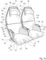
- the Figures 1 to 11 show a seat device according to the invention in a first embodiment.
- the seat device is designed as an aircraft passenger seat device.
- the seat device is designed as part of a seat, in particular as part of an aircraft passenger seat 10 .
- the passenger seat 10 is installed in a passenger cabin of an aircraft in an assembled state.
- the passenger cabin has a cabin floor on which the passenger seat 10 is elevated.
- the cabin floor forms an elevated level for the passenger seat 10 .
- Several passenger seats 10, 60, 62 with the seat device according to the invention are arranged in the passenger cabin.
- the passenger seats 10, 60, 62 are arranged in the passenger cabin in a layout described below.
- the passenger seats 10, 60 are arranged together in a seat row 64 side by side.
- the row of seats 64 is formed by three passenger seats 10, 60 arranged next to one another, one of which is not shown in detail in the drawings. In principle, it would also be conceivable for the row of seats 64 to have a different number of passenger seats 10, 60 or for the passenger seats 10, 60 to be in the form of individual seats that are not arranged in a row of seats. Only one aircraft passenger seat 10 with the seat device according to the invention designed as a passenger seat device is described below.
- the seat device has a stand unit 12 .
- the stand unit 12 is provided to stand the passenger seat 10 and the other passenger seats 60 of the same seat row 64 on the cabin floor.
- the stand unit 12 comprises a plurality of connecting elements, not shown in detail, which couple the stand unit 12 firmly to the cabin floor.
- the connecting elements are preferably provided to be arranged in a form-fitting manner in a fastening rail of the cabin floor and to be fixed in the fastening rail for the fixed connection of the row of seats 64 .
- the seat device comprises a seat bottom unit 14.
- the seat bottom unit 14 is intended to provide a seating area 16 on which a passenger can sit, in particular during a flight.
- the seating area 16 forms a seat surface on which the passenger sits.
- the seat bottom unit 14 is connected to the stand unit 12 .
- the seat bottom unit 14 is rigidly connected to the stand unit 12 .
- the seat bottom unit 14 is pivotably connected to the stand unit 12 via kinematics.
- the seat bottom unit 14 includes a base body 18.
- the base body 18 of the seat bottom unit 14 is connected to the stand unit 12.
- the base body 18 is formed at least partially from a fiber composite material. In principle, it is also conceivable that the base body 18 is formed from a different material, such as a metal.
- the base body 18 has a front area 72 .
- the front area 72 of the base body 18 forms approximately one third of the base body 18 .
- the front area 72 is arranged at a front end of the seat base unit 14 as seen in the direction of the seat 80 .
- the front area 72 faces a front of the passenger seat 10 .
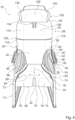
- the base body 18 has two sub-areas 74, 76 which are designed to be separate from one another in a transverse direction 78.
- the transverse direction 78 runs orthogonally to the seat direction 80 and to a vertical direction.
- the two sections 74, 76 which are formed separately from one another, can be moved relative to one another at the same height.
- the two sections 74, 76 which are formed separately from one another, are movable relative to one another in the vertical direction.
- the two sections 74, 76 can be moved independently of one another.
- the two partial regions 74, 76 which are separated from one another in the transverse direction 78 are formed from a flexible material.
- the sub-areas 74, 76 it would also be conceivable for the sub-areas 74, 76 to be formed only partially from a flexible material, with the remainder of the sub-areas 74, 76 being embodied in each case in a rigid manner.
- the two sections 74, 76 have the same dimensions.
- An extension of the partial area 74 in the seat direction 80 and an extension of the partial area 76 in the seat direction 80 are of the same size.
- An extension of the partial area 74 in the transverse direction 78 and an extension of the partial area 76 in the transverse direction 78 are of the same size.
- the base body 18 has a slot 82 in its front region 72 .
- the slot 82 spatially separates the two sections 74, 76 from one another.
- the slot 82 is arranged centrally in the base body 18 in the transverse direction 78 .
- the slot 82 has a width of 20 mm. Basically, it is also conceivable that the slot 82 is made narrower or wider.
- the slot 82 extends from a front end 86 of the base body 18 to a rear end of the front area 72.
- the two partial areas 74, 76 are separated from one another by the slot 82 and can move independently of one another. Basically, it is conceivable that the slot 82 between the two partial areas 74, 76 is covered by a security element to minimize injury.
- the security element is made of a flexible and/or elastic material Material formed that does not prevent mobility of the two sections 74, 76 in an assembled state. It is conceivable, for example, for the security element to be formed from a thin, elastic textile or plastic.
- the safety element is intended to prevent a passenger from being able to be crushed or trapped between the movable partial areas 74 , 76 .
- the base body 18 has a rear area 84 .
- the rear area 84 is designed to be more rigid than the front area 72, in which the base body 18 forms the partial areas 74, 76 that are movable in relation to one another.
- the rear area 84 forms the part of the base body 18 that differs from the front area 72 .
- the rear region 84 is essentially non-elastic.
- the two sub-areas 74, 76 which are formed separately from one another, are connected to one another via the rear area 84.
- the slot 82 which separates the two partial areas 74, 76 in the front area 72, extends from the front end 86 of the base body 18 to a transition from the front area 72 to the rear area 84.
- a rear end of the slot 82 is marked the transition between the front area 72 and the rear area 84.
- the rear area 84 and the at least two partial areas 74, 76 designed to be movable in relation to one another are designed in one piece with one another.
- a transition between the rear area 84 and the respective partial area 74, 76 is flat.
- the base body 18 comprises a thin-walled rear wall 66 for the one-piece formation of the rear region 84 and the two partial regions 74, 76.
- the thin-walled rear wall 66 is designed as a lower wall of the base body 18.
- the thin-walled rear wall 66 is formed from a fiber composite material. In this case, the rear wall 66 is formed by a molded CFRP plate. In principle, it is also conceivable that the thin-walled rear wall 66 is formed from another fiber composite material that appears sensible to a person skilled in the art.
- the thin-walled rear wall 66 has a thickness of about 2 mm. The thin-walled rear wall 66 closes off the base body 18 and thus the seat bottom unit 14 at the bottom.
- the thin-walled rear wall 66 of the base body 18 faces the stand unit 12 arranged under the seat base unit 14 .
- the thin-walled rear wall 66 of the base body 18 has a connection area (not shown) via which the base body 18 and thus the seat base unit 14 is connected to the stand unit 12 .
- the base body 18 also includes a thin-walled front wall 68 for the integral formation of the rear area 84 and the two sub-areas 74, 76.
- the thin-walled front wall 68 is designed as an upper wall of the base body 18.
- the thin-walled front wall 68 is connected to the thin-walled rear wall 66 of the base body 18 .
- the thin-walled front wall 68 is formed from a fiber composite material.
- the thin-walled front wall 68 is formed from the same material as the thin-walled rear wall 66.
- the thin-walled front wall 68 has a thickness of about 2 mm.
- the thin-walled front wall 68 is arranged on an upper side of the base body 18 .
- the thin-walled front wall 68 of the base body 18 is oriented upwards.
- the thin-walled front wall 68 of the base body 18 forms the seating area 16 .
- the base body 18 includes a stiffening element 70.
- the stiffening element 70 is provided to stiffen the base body 18 and thus to stiffen the seat bottom unit 14.
- the stiffening element 70 is arranged between the thin-walled rear wall 66 and the thin-walled front wall 68 of the base body 18 .
- the thin-walled rear wall 66 and the thin-walled front wall 68 enclose the stiffening element 70 .
- the thin-walled rear wall 66 and the thin-walled front wall 68 are connected to one another via the stiffening element 70 in the areas in which they are arranged at a distance from one another.
- the stiffening element 70 is glued to the thin-walled rear wall 66 .
- the stiffening element 70 is glued to the thin-walled front wall 68 .
- the stiffening element 70 is designed as a foam core.
- the thin-walled rear wall 66 and the thin-walled front wall 68 of the base body 18 are connected to one another.
- the thin-walled front wall 68 and the thin-walled rear wall 66 each have a connecting region in a circumferential outer strip, in which the thin-walled front wall 68 and the thin-walled rear wall 66 are connected to one another.
- the thin-walled front wall 68 and the thin-walled rear wall 66 are integrally connected to one another.
- the thin-walled front wall 68 and the thin-walled rear wall 66 which are each formed from a fiber composite material, are preferably connected to one another in a manufacturing process, in particular in a laminating process.
- the thin-walled front wall 68 and the thin-walled rear wall 66 may be subsequently connected in their connection areas by means of a suitable positive, non-positive and/or material connection are firmly connected to each other. It would be conceivable, for example, for the thin-walled front wall 68 and the thin-walled rear wall 66 to be connected to one another in their connection areas by means of an adhesive connection. In principle, it would also be conceivable for the thin-walled front wall 68 and the thin-walled rear wall 66 to be connected to one another in their connection areas via suitable positive-locking elements, such as latching elements.
- the thin-walled front wall 68 and the thin-walled rear wall 66 could be connected in their connection areas via additional side parts, which are optionally subsequently glued to the thin-walled front wall 68 and the thin-walled rear wall 66 or which are already connected to the thin-walled front wall 68 from the outset and the thin-walled rear wall 66 are laminated.
- the thin-walled front wall 68 and the thin-walled rear wall 66 are spaced apart from one another, apart from the connection regions in which the thin-walled front wall 68 and the thin-walled rear wall 66 are connected to one another and thus merge into one another.
- the thin-walled front wall 68 and the thin-walled rear wall 66 form a gap in the rear area 84 .
- the stiffening element 70 embodied as a foam core is arranged in the intermediate space which is spanned in the rear area 84 by the thin-walled front wall 68 and the thin-walled rear wall 66 .
- the rear region 84 is stiffened by the stiffening element 70 .
- the thin-walled front wall 68 and the thin-walled rear wall 66 are connected to one another directly and over a large area.
- the base body 18 has only the thin-walled front wall 68 and the thin-walled rear wall 66 in the two partial areas 74, 76. Since in the sections 74, 76 only the thin-walled front wall 68 and the thin-walled rear wall 66 are connected to each other without including a stiffening element, the sections 74, 76 are much more flexible than the rear section 84.
- the sections 74, 76 have a Basic position, in which both have the same orientation to the rear area 84.
- the basic position forms an undeflected position of the partial areas 74, 76, in which essentially no external force, in particular no force caused by a passenger sitting on the passenger seat 10, acts on the partial areas 74, 76.
- the partial areas 74 , 76 are aligned approximately parallel to the rear area 84 . If the sections 74, 76 by an external force, for example by one of a on the Air passenger seat 10 seated passenger caused force, deflected, an internal stress is generated in the sub-regions 74, 76 by the elastic deformation of the sub-regions 74, 76, which forms a restoring force.
- the partial areas 74, 76 are returned to their respective basic position after a force which led to the deflection has ceased to exist.
- the restoring force generated during an adjustment forms a counterforce that counteracts the force that causes the adjustment.
- the partial areas 74, 76 yield to different degrees.
- the partial area 74, 76 which is arranged on the corresponding side of the passenger seat 10 can advantageously yield further and a load on the body part which is on the corresponding Section 74, 76, for example on a thigh rests relieve.
- a particularly comfortable position can be taken by the passenger.
- the seat base can advantageously be made comfortable by the flexible partial areas 74, 76.
- the seat bottom unit 14 includes a cushion element 20.
- the cushion element 20 is firmly connected to the base body 18 of the seat bottom unit 14.
- the padding element 20 is formed from a foam. In principle, it is also conceivable for the padding element 20 to be formed from a different, at least partially elastic material that appears sensible to a person skilled in the art.
- the upholstery element 20 is covered by a cover, not shown in detail, which is detachably connected to the upholstery element 20 . The cover can be easily removed from the upholstery element 20 to change it. It is conceivable that the cover is pulled both over the upholstery element 20 and also partially over the base body 18 . For the further description of the upholstery element 20, the reference should also be understood implicitly.
- the upholstered element 20 forms the seat area 16 of the seat bottom unit 14 .
- the seating area 16 has a rear area 22 and a front portion 24 on.
- the front area 24 of the seat area 16 is arranged at a front end of the seat bottom unit 14 as seen in the seat direction 80 of the aircraft passenger seat 10 .
- the rear area 22 of the seat bottom unit 14 is arranged at a rear end of the seat bottom unit 14 as seen in the seat direction 80 .
- the seat area 16 forms a taper in the rear area 22 .
- the padding element 20 is narrower in the rear area 22 than in the front area 24.
- a seat surface formed by the seat area 16 is narrower in the rear area 22 than in a front area 24.
- a width of the seat area 16 in the front area 24 is 450mm.
- the width of the seat area 16 in the front area 24 is between 400 mm and 600 mm.
- a minimum width of the seating area 16 in the rear area 22 is 250 mm.
- the width of the seat area 16 in the rear area 22 is between 200 mm and 450 mm.
- the minimum width of the seat area 16 in the front area 24 is at least 30% greater than the minimum width of the seat area 16 in the rear area 22.
- the width of the rear area 22 of the seat area 16 counter to the seat direction 80 steadily decreases. A decrease in the width of the rear area 22 is not uniform. In principle, however, it is also conceivable for the width of the rear region 22 to decrease continuously.
- the rear area 22 of the seat area 16 forms approximately the rear third of the seat area 16 .
- the padding element 20 has a slot 88 at a front end, which runs congruently with the slot 82 of the base body 18 in a mounted state.
- the front area of the cushion element 20 also has two separate partial areas 74, 76, which can be moved independently of one another. In principle, however, it is also conceivable that the padding element 20 does not have a slot 88 and forms a continuous front end.
- the seat device includes a backrest unit 26.
- the backrest unit 26 is provided for the purpose that a passenger sitting on the passenger seat 10 can lean on his back.
- the backrest unit 26 is attached to the rear end of the seat bottom unit 14 .
- the backrest unit 26 delimits the seating area 16 to the rear.
- the backrest unit 26 is rigidly connected to the seat bottom unit 14 . In principle, it is also conceivable that the backrest unit 26 and the seat bottom unit 14 are pivotably connected to one another via kinematics.
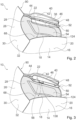
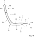
- the backrest unit 26 includes a rigid section 90.
- the rigid section 90 is designed as a lower section of the backrest unit 26.
- the lower rigid portion 90 faces the seat bottom unit 14 .
- the lower partial area 90 of the backrest unit 26 forms a first base body 28 of the backrest unit 26 .
- the base body 28 of the backrest unit 26 partially forms a supporting structure of the backrest unit 26 .
- the first base body 28 of the backrest unit 26 is formed in one piece with the base body 18 of the seat base unit 14 .
- the base body 28 of the lower rigid partial area 90 is formed by the thin-walled rear wall 66 , the thin-walled front wall 68 and the stiffening element 70 arranged between the thin-walled rear wall 66 and the thin-walled front wall 68 .
- the thin-walled front wall 68 extends upwards from the seat base unit 14 in a region of the lower partial region 90 of the backrest unit 26 on a front side of the backrest unit 26 .
- the thin-walled rear wall 66 points upwards from the seat bottom unit 14 in a region of the lower partial region 90 of the backrest unit 26 on a rear side of the backrest unit 26 .
- the transitions between the thin-walled front wall 68 and the thin-walled rear wall 66 between the backrest unit 26 and the seat bottom unit 14 are each formed by radii. Due to the one-piece design of the base body 18, 28 of the seat base unit 14 and the lower portion 90 of the backrest unit 26, the seat base unit 14 and the lower portion 90 of the backrest unit 26 are rigidly connected to each other.
- the seat bottom unit 14 and the lower portion 90 of the backrest unit 26 have a fixed, unchangeable angle to one another.
- a seat angle between the backrest unit 26 and the seat base unit 14 in a basic position is defined by the angle that the seat base unit 14 and the lower partial area 90 of the backrest unit 26 have to one another.
- the seat angle between the backrest unit 26 and the seat bottom unit 14 is 130 degrees.
- the base body 28, which forms the lower portion 90 of the backrest unit 26 from the base body 18 of the seat bottom unit 14, is formed separately. It would be conceivable that the base body 28 of the backrest unit 26 is also constructed in a sandwich construction and consists of a thin-walled front wall, a thin-walled rear wall and a stiffening element. The one formed separately from the base body 18 of the seat bottom unit 14 The first base body 28 of the backrest unit 26 would be firmly and rigidly connected to the base body 18 of the seat bottom unit 14 during assembly by means of a type of connection that appears sensible to a person skilled in the art, for example a screw connection.
- the base bodies 18, 28 In such a configuration of the base bodies 18, 28, a pivotable connection between the base bodies 18, 28 would also be conceivable.
- the base body 28 it is also conceivable for the base body 28 to be formed from a different material that the person skilled in the art considers appropriate, such as a metal, for example.
- the backrest unit 26 has an upper portion 92 .
- the upper section 92 is designed to be pivotable relative to the lower section 90 .
- the backrest unit 26 has a second base body 94 which forms the upper partial area 92 .
- the base body 94 is essentially formed from a fiber composite material.
- the base body 94 is designed in a sandwich construction.
- the base body 94 has a thin-walled rear wall 96, a thin-walled front wall 98 and a stiffening element, not shown in detail, enclosed therein.
- a structure of the base body 94 corresponds approximately to that of the base body 18 of the seat bottom unit 14. In principle, it is also conceivable for the base body 94 to be formed from another material that the person skilled in the art considers appropriate, such as a metal.
- the backrest unit 26 includes a bearing unit 100.
- the bearing unit 100 allows the lower section 90 and the upper section 92 to be pivoted relative to one another.
- the bearing unit 100 pivotally connects the first base body 28 of the backrest unit 26, which forms the lower section 90, to the second base body 94 of the backrest unit 26.
- the bearing unit 100 has a maximum pivoting range of approximately 35 degrees, by which the lower section 90 and the upper portion 92 are pivotable to each other. In principle, a swivel range of 40 to 50 degrees is also possible.
- the bearing unit 100 which supports the rigid lower section 92 with the upper pivotable section 92 has a pivot axis 102 .
- the pivot axis 102 is offset forward in the seat direction 80 with respect to a rear end of the backrest unit 26 .
- the pivot axis 102 is arranged in front of the thin-walled rear wall 96 or the thin-walled rear wall 66, as seen in the seat direction 80.
- FIG. The pivot axis 102 is, viewed in the seat direction 80, arranged in front of the thin-walled front wall 68, 98 and the thin-walled rear wall 66, 96, respectively.
- the first base body 28 and the second base body 94 each form an elevation 104, 106 extending in the seat direction 80 in their outer regions on sides facing one another.
- the bearing mounts are connected to one another via a bearing element 108 .
- the bearing element 108 is designed as a bearing bolt. In principle, it is also conceivable that the bearing element 108 is designed as another bearing element that appears sensible to a person skilled in the art.
- the base body 28 and the base body 94 can be pivoted relative to one another via the bearing element 108 .
- the bearing unit 100 has a plurality of stop elements 110, 112 which limit the lower partial area 90 and the upper partial area 92 to their maximum positions in relation to one another.
- a stop element 110 is formed by the base body 94 which forms the upper partial area 92 .
- the stop element 112 is formed by the base body 28 which forms the lower partial area 90 .
- a comfort position which is designed as a basic position
- the two stop elements 110, 112 rest against one another and thereby fix the lower partial area 90 and the upper partial area 92 of the backrest unit 26 to one another.
- the bearing unit 100 has further stop elements, not shown in detail, which contact one another in a TTL position of the backrest unit 26 and thereby fix the lower partial area 90 and the upper partial area 92 of the backrest unit 26 in the TTL position to one another.
- the backrest unit 26 forms a backrest support surface 30 .
- the backrest unit 26 comprises a first upholstery element 32 and a second upholstery element 114.
- the first upholstery element 32 is attached to a front side of the first base body 28 of the backrest unit 26.
- the first upholstery element 32 forms the backrest support surface 30 in the lower partial area 90 of the backrest unit 26 .
- the backrest unit 26 has a plurality of connection elements, not shown in detail, which are correspondingly integrated into the base body 28 and the upholstery element 32 .
- the connection elements are designed as loop and hook tapes.
- connection elements are designed in a different way that appears sensible to the person skilled in the art as positive and/or non-positive locking elements, such as snaps.
- the padding element 32 is made of an elastic material, such as in particular a foamed plastic. In principle, it is also conceivable for the padding element 32 to be formed from another elastic plastic and/or natural material that appears sensible to a person skilled in the art.
- the upholstered element 32 forms the backrest support surface 30 on its front side facing away from the base body 28 .
- the upholstery element 32 has a cover, not shown or designated in detail, which closes the upholstery element 32 on the backrest support surface 30 . The cover can be separated from the upholstery element 32 and can be separated from the upholstery element 32 for cleaning or replacement.
- the second pad member 114 is attached to a front side of the second base body 94 of the backrest unit 26 .
- the second upholstered element 114 forms the backrest support surface 30 in the upper partial area 92 of the backrest unit 26 .
- the backrest unit 26 has a plurality of connection elements, not shown in detail, which are correspondingly integrated into the base body 94 and the upholstery element 114 .
- the connection elements are designed as loop and hook tapes.
- the backrest support surface 30 has a lower area which is formed by the upholstery element 32 .
- the lower area of the backrest support surface 30 is arranged on a side of the backrest unit 26 facing the seat bottom unit 14 .
- the lower area of the backrest support surface 30 faces the cabin floor in an assembled state.
- the backrest support surface 30 has an upper area which is formed by the upholstery element 114 .
- the upper area of the backrest support surface 30 is arranged on a side of the backrest unit 26 facing away from the seat bottom unit 14 .
- the upper area of the backrest support surface 30 faces away from the cabin floor in an assembled state.
- the backrest support surface 30 has a taper at the lower end.
- the backrest support surface 30 is narrower in the lower area than in the upper area.
- the lower area of the backrest support surface 30 has a width that is more than 50% smaller than a width of the backrest support surface 30 in the upper area.
- a transition between the upper, wide area of the backrest support surface 30 and the lower, narrow area of the backrest support surface 30 is formed by a radius.
- the rejuvenation of Seat back support surface 30 increases in the lower region from a transition from the upper region to a lower end of the seat back support surface 30 .
- the lower area, which forms the tapering of the backrest support surface 30, is wider at an upper end facing the upper area than at the lower end facing away from the upper area.
- the narrowing it is also conceivable for the narrowing to have the same width over its entire length.
- the backrest unit 26 forms contact elements 116, 118 which extend laterally forwards.
- the contact elements 116, 118 are provided so that a passenger sitting on the passenger seat 10 can lean against the contact elements 116, 118 laterally.
- the contact elements 116, 118 each extend from a lower area of the upper partial area 92 of the backrest unit 26 to an upper area of the lower partial area 90 of the backrest unit 26.
- the contact elements 116, 118 rise steadily from the backrest support surface 30 in a radius , until they have their maximum extent approximately in the area of the bearing unit 100 and then steadily decrease in a radius down to the backrest support surface 30 .
- Upper sections of the contact elements 116, 118 are formed by the cushion element 114, which is arranged on the base body 94 of the upper section 92 of the backrest unit 26.
- Lower partial areas of the contact elements 116, 118 are formed by the cushion element 32, which is arranged on the base body 28 of the lower partial area 90 of the backrest unit 26.
- the backrest unit 26 has a headrest 126 .
- the headrest 126 is arranged at an upper end of the upper section 92 of the backrest unit 26 .
- the headrest 126 includes a headrest element 128.
- the headrest element 128 is designed as a padded element.
- the headrest element 128 forms a forward-projecting support element 130, 132 at each of its two lateral ends, which in each case provides a lateral support surface for a passenger's head.
- a passenger can comfortably support his head on the side of the headrest 126, as a result of which the headrest 126 is particularly well suited for side sleepers.
- the supporting elements 130, 132 can be adjusted at an angle to the headrest element 128.
- the height of the headrest 126 in relation to the backrest unit 26 can be adjusted.
- the headrest 126 comprises a linear guide 134.
- the height of the headrest element 128 can be adjusted in relation to the backrest unit 26 via the linear guide 134 .
- the linear guide 134 has a guide rail 136 firmly connected to the backrest unit 26 .
- the headrest element 128 comprises a guide element which is designed to correspond to the guide rail 136 and is not shown in detail, which is guided in the guide rail 136 .
- a movement of the guide element to the guide rail 136 is designed to be self-locking.
- a force must be exerted along a displacement axis of the guide rail 136 that is greater than a force that is exerted on the head support element 128 during operation by a head resting on the head support element 128. This prevents the headrest element 128 from being inadvertently adjusted.
- the headrest 126 it is also conceivable for the headrest 126 to have a locking mechanism which locks the headrest 126 in the various positions, with a passenger having to unlock it manually, for example by means of a push button.
- the seat device also includes a first armrest unit 34.
- the seat device also includes a second armrest unit 36.
- the two armrest units 34, 36 are intended to delimit the seat area 16 laterally.
- the armrest units 34, 36 delimit the seat area 16 on two opposite sides of the seat base unit 14.
- the armrest units 34, 36 delimit the seat area 16 in a direction orthogonal to a seat direction of the passenger seat 10.
- the armrest units 34, 36 are designed to be equivalent to one another.
- the first armrest unit 34 and the second armrest unit 36 are mirror images. In the following, therefore, only the first armrest unit 34 is described in more detail, it being possible for the description to be transferred to the second armrest unit 36, which is of identical design as a mirror image.
- the armrest unit 34 is intended to provide a support surface 38 for a passenger seated on the passenger seat 10 .
- the support surface 38 is provided so that a passenger can at least partially rest his arm and/or his hand on it.
- the armrest unit 34 comprises a supporting and/or separating element 40.
- the supporting and/or separating element 40 is intended to provide a supporting surface 42 for the passenger. In this case, the supporting and/or separating element 40 forms a lateral supporting surface 42 .
- the support surface 42 is towards the seating area 16 aligned.
- the support surface 42 is aligned essentially orthogonally to the seating surface formed by the seating area 16 .
- the support surface 42 runs essentially orthogonally to the cabin floor.
- the supporting and/or separating element 40 extends forward from the backrest unit 26 at a distance from the seat bottom unit 14 .
- the supporting and/or separating element 40 is connected to the backrest unit 26 at a rear end facing the backrest unit 26 .
- the supporting and/or separating element 40 is rigidly connected to the backrest unit 26 .
- the supporting and/or dividing element 40 and the backrest unit 26 each have correspondingly designed connection areas, not shown in detail, via which the supporting and/or dividing element 40 is rigidly connected to the Backrest unit 26 is connected.
- the supporting and/or separating element 40 is connected to the backrest unit 26 via a screw connection that is not shown in detail.
- the supporting and/or separating element 40 it is also conceivable for the supporting and/or separating element 40 to be firmly connected to the backrest unit 26 via another form-locking, non-positive and/or material connection that appears sensible to the person skilled in the art. In principle, it is also conceivable for the supporting and/or separating element 40 to be pivotably coupled to the backrest unit 26 via kinematics.
- the supporting and/or separating element 40 has an upper edge 44 which forms a contour of the supporting and/or separating element 40 which faces away from the seat bottom unit 14 .
- the upper edge 44 has different heights in different areas of the supporting and/or separating element 40 . As a result, the supporting and/or separating element 40 has different heights in the different areas.
- the supporting and/or separating element 40 has a rear region which faces the backrest unit 26 .
- the supporting and/or separating element 40 has a central region which adjoins a side of the rear region of the supporting and/or separating element 40 which faces away from the backrest unit 26 .
- the supporting and/or separating element 40 has a height that is smaller than a height in the central area of the supporting and/or separating element 40.
- the supporting and/or separating element 40 is in that of the backrest unit 26 facing area flatter to create a clearance for an elbow of the passenger sitting on the seat.
- the upper edge 44 forms a support surface in the rear area, in particular for the elbow of a passenger.
- the supporting and/or separating element 40 has a front area which is on a rear area is arranged opposite side of the central area. In the front area, the supporting and/or separating element 40 again has a lower height than in the middle area. The contour is curved from the rear area over the middle area to the front area. The height of the supporting and/or separating element 40 increases in a transition from the rear area to the front area in an arc, with a maximum height of the supporting and/or separating element 40 being reached shortly after the transition to the middle area. From the maximum height, the height of the supporting and/or separating element 40 steadily decreases in an arc up to the front end of the supporting and/or separating element 40 . The supporting and/or separating element 40 forms approximately the shape of half an arrowhead.
- the armrest unit 34 has a first support element 46 to form the support surface 38 .
- the support element 46 is provided to form the support surface 38, which is aligned essentially parallel to the seat surface, in at least one operating state.
- the support element 46 has a wing shape.
- the support element 46 has a rear region which faces the backrest unit 26 .
- a rear end of the support element 46 is arranged at a distance from the backrest unit 26 in an assembled state.
- the first support element 46 is adjustable between different positions.
- the first support element 46 is pivotable.
- the first support element 46 is pivotably mounted relative to the supporting and/or separating element 40 .
- the first support element 46 can be pivoted between a rest position and a use position.
- the support element 46 In a rest position, the support element 46 is folded onto the supporting and/or separating element 40 . In the rest position of the support element 46, the support surface 38, which forms the support element 46, cannot be used by a passenger for support. A part of the supporting surface 38, which is formed by the supporting element 46, faces the supporting surface 42 of the supporting and/or separating element 40 in the rest position. In the position of use, the support element 46 is folded away from the supporting and/or separating element 40 . An angle between the supporting surface 42 of the supporting and/or separating element 40 and the bearing surface 38 of the first bearing element 46 is approximately 90 degrees in the position of use. In the position of use, the supporting and/or separating element 40 and the supporting element 46 essentially form an L-shape.
- the support element 46 In the rest position, the support element 46 forms a support surface 58 .
- the support surface 58 of the support element 46 is formed by an underside of the support element 46 opposite the support surface 38 .
- the support surface 58 In the position of use, the support surface 58 is oriented downwards and faces the seat bottom unit 14 .
- the supporting surface 58 In the rest position, in which the support element 46 is folded onto the supporting and/or separating element 40 , the supporting surface 58 is directed inwards and faces the seating area 16 .
- a passenger can lean against the support surface 58 .
- the passenger can advantageously position himself comfortably in the passenger seat 10 and support himself laterally on the support surface 58 of the support element 46 .
- the armrest unit 36 has a further support element 48 .
- the additional support element 48 is provided to at least partially form the support surface 38 for the passenger.
- the further bearing element 48 is arranged between the supporting and/or separating element 40 and the first bearing element 46 .
- the additional support element 48 is rigidly connected to the supporting and/or separating element 40 .
- the further support element 48 is formed in one piece with the supporting and/or separating element 40 .
- the additional support element 48 it is also conceivable for the additional support element 48 to be connected to the supporting and/or separating element 40 in a positive, non-positive and/or material connection. It is conceivable, for example, for the support element 48 to be connected to the supporting and/or separating element 40 via a screw connection or an adhesive connection.
- a transition between the support surface 42 formed by the support and/or separating element 40 and the support surface 38 formed by the further support element 48 is formed by a radius.
- the armrest unit 34 has a hinge 50 for the pivotable mounting of the first supporting element 46 relative to the supporting and/or separating element 40 .
- the hinge 50 is arranged between the first support element 46 and the further support element 48 .
- the hinge 50 is partially formed by the first support element 46 and partially by the further support element 48 .
- the first support element 46 has a plurality of through-holes which are arranged at a distance from one another and are separated from one another by recesses.
- the further support element 48 also forms through-holes, which are introduced into molded webs, which correspond to the recesses are formed, which has the first support member 48 between its through holes.
- the webs formed onto the further support element 48 are arranged in the recesses of the first support element 46, as a result of which the through-holes of the first support element 46 and the further support element 48 are aligned.
- the hinge 50 has a pin element which is guided through the through-holes of both bearing elements 46, 48 of the hinge 50 for the pivotable connection of the first bearing element 46 and the further bearing element 48.
- the two support elements 46, 48 can be pivoted relative to one another via the pin element.
- the pin element forms a pivot axis 52 about which the first bearing element 46 can be pivoted relative to the supporting or separating element 40 .
- the pivot axis 52 runs along a main extension of the armrest unit 34.
- the pivot axis 5a runs essentially parallel to the seat direction 80. parallel to the seat direction 80.
- the hinge 50 has a stop element 138, which the first support element 46 in the use position and in the rest position holds.
- the stop element 138 is designed as a stop element that is rigidly connected to the support element 46 . In the position of use, the stop element 138 strikes a stop, not shown in any more detail, below the support element 48, so that the support element 46 is fixed in the position of use.
- the hinge 50 has one or more locking elements that fix the first support element 46 in the use position and in the rest position.
- the first support element 46 is linked to a lower end of the armrest unit 34 by being mounted via the hinge 50 .
- the seat assembly includes a first support member 54.
- the support member 54 spans an area between the seat bottom assembly 14 and the armrest assembly 34.
- the seat assembly includes a second support member 56 forming an area between the seat bottom assembly 14 and the armrest assembly 36.
- the support element 56 is designed as a mirror image of the support element 54 . Since the supporting elements 54, 56 represent essentially identical mirror images of one another, only the first supporting element 54 is described in more detail below. The following description of the first support element 54 can also be used to explain the second support element 56 .
- the support element 54 which spans the area between the seat bottom unit 14 and the armrest unit 34, is provided for the purpose that the passenger sitting on the passenger seat 10 can support his lower back thereon.
- the support element 54 is provided for lateral support of the passenger.
- the support element 54 is arranged in the area between the seat bottom unit 14 , the armrest unit 34 and the backrest unit 26 .
- the support element 54 is designed as a covering element.
- the support element 54 designed as a covering element is stretched between the armrest unit 34 , the seat bottom unit 14 and the backrest unit 26 .
- the supporting element 54 designed as a covering element is formed by a net. In principle, it is also conceivable that the supporting element 54 designed as a covering element is made of fabric or another elastic material, such as leather or a thin plastic element.
- the support member 54 is connected to the armrest unit 34 at an upper end.
- the support member 54 extends over an entire length of the armrest unit 34.
- the support member 54 is attached to a lower side of the support member 48. As shown in FIG. In principle, it is also conceivable that the support element 54 is attached to another component of the armrest unit 34 .
- the support element 54 has a connection area that is not shown in detail.
- the connection area is arranged at the upper end of the support element 54 .
- the connection area has at least one connection element via which the support element 54 can be connected to the armrest unit 34 .
- the connection element is designed as a positive and/or non-positive connection element, for example as a loop and hook strip or as part of a zip fastener.
- the support element 54 is connected to the armrest unit 34 in the connection area via a clamp connection.
- the support element 54 it would also be conceivable for the support element 54 to be connected in its connection area to the armrest unit 34, in particular to the support element 48, via a material connection, such as in particular an adhesive connection.
- the support element 54 is connected to the backrest unit 26 at a rear end.
- the support element 54 has a connection area (not shown) at its rear end. With the connection area, not shown, the support element 54 is connected to the first Main body 28 of the backrest unit 26 connected.
- the connection area has at least one connection element via which the support element 54 can be connected to the first base body 28 of the backrest unit 26 .
- the connection element is designed as a positive and/or non-positive connection element, for example as a loop and hook strip or as part of a zip fastener. In principle, it is also conceivable that the support element 54 is connected to the base body 28 of the backrest unit 26 in the connection area via a clamp connection.
- the support element 54 may be connected to the backrest unit 26 via a piping connection.
- the support element 54 it would also be conceivable for the support element 54 to be connected in its connection area to the base body 28 of the backrest unit 26 via a material connection, such as in particular an adhesive connection.
- the support element 54 connects directly to the taper in the backrest support surface 30 .
- the support member 54 extends inward at a rear end toward the seat bottom unit 14 from an upper point where the support member 54 is connected to the armrest unit 34 .
- the support element 54 merges into the backrest support surface 30 on its side facing the backrest unit 26 .
- the support element 54 is connected to the seat bottom unit 14 at its lower end.
- the support element 54 is connected to the base body 18 of the seat bottom unit 14 .
- the support element 54 includes a connection area.
- the support element 54 is firmly connected to the base body 18 via the connection area.
- the support element 54 is not firmly connected to the base body 18 of the seat base unit 14 via the connection area, but is merely clamped between the base body 18 and the upholstered element 20 .
- the support element 54 it would also be conceivable for the support element 54 to be connected to the base body 18 of the seat bottom unit 14 via a piping connection. In an assembled state, the support element 54 connects directly to the narrowing of the seat bottom unit 14 .
- the support element 54 extends from a front end, which is arranged approximately at the front end of the armrest unit 34 facing away from the backrest unit 26, from the outside in the direction of the backrest unit 26 inwards.
- the support member 54 extends furthest inward. From that At the point where the taper of the backrest support surface 30 and the taper of the seat bottom unit 14 meet, the support element 54 extends outwardly as viewed in the direction of the seat. From the point at which the tapering of the backrest support surface 30 and the tapering of the seat bottom unit 14 meet, the support element 54 extends in the direction of the backrest unit 26, that is to say viewed upwards, also outwards.
- the support element 54 is designed as a covering element.
- the support element 54 designed as a covering element is stretched in the area between the armrest unit 34 , the seat bottom unit 14 and the backrest unit 26 .
- the support element 54 designed as a covering element is made from a flexible material.
- the supporting element 54 designed as a covering element is formed by a textile.
- the support element 54 is formed by a net.
- the support element 54 is formed from a substance or another flexible material. It is conceivable that the support element 54 is formed from a plastic plate, for example.
- the armrest unit 34 has a stiffening element 124 .
- the stiffening member 124 is attached to a front end of the support member 54 .
- the stiffening element 124 is intended to keep the support element 54 in shape in its front area.
- the stiffening element 124 is designed as a web to which the support element 54 is connected.
- the stiffening element 124 connects the armrest unit 34 to the seat bottom unit 14.
- the stiffening element 124 is arranged at the front end of the armrest unit 34 and extends from an underside of the armrest unit 34 downward in the direction of the seat bottom unit 14.
- the stiffening element is at its lower end 124 is firmly connected to the seat bottom unit 14, in particular to the base body 18 of the seat bottom unit 14.
- stiffening element 124 it is also conceivable for the stiffening element 124 to be designed merely as a reinforcement that is introduced into the support element 54 formed by a textile. It would be conceivable, for example, for a web to be sewn into the support element 54 .
- the seat device includes an adjustment unit that is not shown in detail.
- the setting unit has a locking mechanism which can lock the support element 54, which is designed as a covering element, at different lengths.
- the size of the support element 54 stretched between the seat bottom unit 14, the armrest unit 34 and the backrest unit 26 can be adjusted by the locking mechanism.
- the locking mechanism has a clamping element that clamps the support element 54 on one side.
- the support element 54 Depending on how hard or soft the support element 54 is set, a greater or lesser part of the support element 54 in the area between the seat bottom unit 14, the armrest unit 34 and the backrest unit 26 is released.
- the support member 54 is set hard, an excess portion of the support member 54 is located behind the locking mechanism and is unusable by the passenger. As a result, the support element 54 is under more tension and cannot be deflected as far by a passenger. If the support element 54 is set softer, the excess part that was previously clamped behind the clamping element is released and is now also located in the area between the seat bottom unit 14, the armrest unit 34 and the backrest unit 26 Passenger are further deflected.
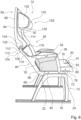
- the passenger seat 10 with the seat device can be positioned in different seat positions.
- the backrest unit 26 connected to the seat bottom unit 14 is positioned differently in the different seating positions.
- a first seating position, in which the backrest unit 26 or the passenger seat 10 can be positioned, is designed as the comfort position.
- the comfort position is in the figure 7 shown.
- the comfort position is designed as a basic position optimized for the passenger.
- the basic position is designed as a position for which all parameters of the seat are optimally designed in order to achieve the best possible comfort for a passenger in the comfort position.
- the backrest unit 26 forms a backrest support surface 30 that is essentially planar.
- the backrest support surface 30 has an incline of substantially 135 degrees to the pad plane.
- the lower, rigid section 90 of the backrest unit 26 and the upper, pivotable section 92 are essentially aligned with one another in one plane and are not pivoted with respect to one another (see FIG figure 7 ).
- the upholstered elements 32, 114 form an essentially planar backrest support surface 30. There is essentially no offset in a transition between the cushion element 32 and the cushion element 114 in the comfort position.
- the backrest unit 26, whose sections 90, 92 are essentially aligned with one another in one plane, and the seat floor unit 14 enclose a seat angle of 130 degrees.
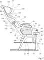
- TTL position Another seating position is designed as the TTL position.
- the upper pivotable portion 92 In the TTL position, the upper pivotable portion 92 is erected and oriented substantially perpendicular to the stand plane.
- the TTL position represents a maximum adjustment of the upper section 92 to the lower section 90 of the backrest unit 26.
- the upper section 92 In the TTL position, the upper section 92 is pivoted by essentially 30 degrees to the lower section 90.
- the upper sub-area 92 can be continuously adjusted and locked between the comfort position and the TTL position relative to the lower sub-area 90 .
- the seat device comprises a locking unit that is not shown in detail.
- the locking unit locks the upper sub-area 92 in the various positions relative to the lower sub-area 90.
- the locking unit has a compression spring, for example, which fixes the two sub-areas 90, 92 to one another and uses an actuating element by the operator to adjust the two Sections 90, 92 can be unlocked.
- a locking unit known from the prior art is conceivable here, which is provided for adjusting a backrest unit 26 in relation to the seat base unit 14 .
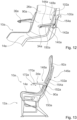
- the figures 9 and 10 each show a part of a layout with several passenger seats 10, 60, 62 with the seat device according to the invention.
- the passenger seats 10, 60, 62 are elevated in the aircraft cabin.
- the passenger seats 10, 60, 62 are arranged in a different way.
- the passenger seats 10, 62 are arranged one behind the other in a longitudinal row 120 of seats.
- the aircraft passenger seats 10, 62 arranged one behind the other in the longitudinal seat row 120 have a pitch spacing of 33 inches.
- a longitudinal row 120 of seats preferably more than 10 passenger seats 10, 62 are arranged one behind the other in the aircraft cabin.
- the backrest unit 26 of the front passenger seat 10 extends over a seat floor unit 122 of the rear passenger seat 62.
- the front passenger seat 10 and the rear passenger seat 62 overlap at least partially.
- an upper partial area 92 of the backrest unit 26 is arranged above the seat bottom unit 122 of the rear passenger seat 62, viewed in a vertical direction.
- An overlap of the backrest unit 26 of the front passenger seat 10 in the comfort position with the seat bottom unit 122 of the rear passenger seat 62 is 3.5 inches.
- an overlap is designed to be larger or smaller.
- the two passenger seats 10, 62 arranged one behind the other do not have any overlap.
- the backrest unit 26 of the front passenger seat 10 does not overlap with the rear passenger seat 62.
- a passenger can advantageously easily get into his passenger seat 62.
- All aircraft passenger seats 10, 62 arranged in a longitudinal row 120 of seats are arranged at the same distance from one another.
- the Figures 12 and 13 show a seat device according to the invention in a second embodiment.
- the seat device is designed as an aircraft passenger seat device.
- the seat device is designed as part of a seat, in particular as part of an aircraft passenger seat 10a.
- the seat device has a stand unit 12a.
- the Stand unit 12a is provided to stand the passenger seat 10a on a cabin floor.
- the seat device includes a seat bottom unit 14a.
- the seat bottom unit 14a is intended to provide a seating area 16a on which a passenger can sit, in particular during a flight.
- the seating area 16a forms a seat surface on which the passenger sits.
- the seat bottom unit 14a is connected to the stand unit 12a.
- the seat bottom unit 14a is rigidly connected to the stand unit 12a.
- the seat bottom unit 14a includes a base body 18a.
- the base body 18a of the seat bottom unit 14a is connected to the stand unit 12a.
- the base body 18a is formed at least partially from a fiber composite material.
- the base body 18a it is also conceivable for the base body 18a to be formed from a metal, such as magnesium in particular.
- the base body 18a is particularly preferably formed from a magnesium die-cast.
- the seat device includes a backrest unit 26a.
- the backrest unit 26a is provided so that a passenger sitting on the passenger seat 10a can lean on his back.
- the backrest unit 26a is attached to the rear end of the seat bottom unit 14a.
- the backrest unit 26a delimits the seating area 16a to the rear.
- the backrest unit 26a is rigidly connected to the seat bottom unit 14a.
- the backrest unit 26a includes a rigid portion 90a.
- the rigid portion 90a is formed as a lower portion of the backrest unit 26a.
- the lower rigid portion 90a faces the seat bottom unit 14a.
- the lower partial area 90a of the backrest unit 26a forms a first base body 28a of the backrest unit 26a.
- the base body 28a of the backrest unit 26a partially forms a supporting structure of the backrest unit 26a.
- the first base body 28a of the backrest unit 26a is formed in one piece with the base body 18a of the seat bottom unit 14a.
- the base body 28a of the lower rigid partial area 90a is formed by a thin-walled rear wall 66a, a thin-walled front wall 68a and a stiffening element 70a arranged between the thin-walled rear wall 66a and the thin-walled front wall 68a.
- the base body 28a of the lower partial area 90a can in principle also be embodied as a frame with a covering. It is conceivable that the frame, which forms part of the base body 28a, is formed from a metal or a fiber composite material. A fabric covering is connected under tension to the frame and forms a support surface for the passenger.
- the backrest unit 26a has an upper portion 92a.
- the upper portion 92a is pivotable to the lower portion 90a.
- the backrest unit 26a has a second base body 94a, which forms the upper partial area 92a.
- the base body 94a is essentially formed from a fiber composite material.
- the base body 94a of the upper partial area 92a can in principle also be embodied as a frame with a covering. It is conceivable that the frame, which forms part of the base body 94a, is formed from a metal or a fiber composite material. A fabric covering is connected under tension to the frame and forms a support surface for the passenger.
- the backrest unit 26a includes a bearing unit 100a.
- the lower partial area 90a and the upper partial area 92a can be pivoted relative to one another via the bearing unit 100a.
- the bearing unit 100a pivotally connects the first base body 28a of the backrest unit 26a, which forms the lower partial area 90a, to the second base body 94a of the backrest unit 26a.
- the bearing unit 100a has a pivot axis 102a about which the upper portion 92a can be pivoted relative to the lower portion 90a.
- the bearing unit 100a further includes a spring element that is not shown in detail.
- the spring element is intended to exert a force on the upper partial area 92a so that it is pressed in the direction of the TTL position of the passenger seat 10a. As a result, a passenger experiences resistance when adjusting to the TTL position and can thus comfortably reach the TTL position. When adjusting from the TTL position, the spring element provides an assisting force.
- the seat assembly further includes a first armrest unit 34a.
- the seat device further includes a second armrest unit 36a.
- the two armrest units 34a, 36a are intended to delimit the seat area 16a laterally.
- the armrest units 34a, 36a delimit the seat area 16a on two opposite sides of the seat bottom unit 14a.
- the armrest units 34a, 36a each have a base body 140a.
- the base body 140a of the armrest units 34a, 36a each has a bearing unit 142a.
- the base bodies 142a of the armrest units 34a, 36a are arranged with the lower partial area 90a of the backrest unit 26a by means of the bearing unit 142a.
- the armrest units 34a, 36a can be pivoted to the backrest unit 26a via the bearing unit 142a.
- the armrest units 34a, 36a are between a use position, in which they are aligned essentially parallel to the seat bottom unit 14a, and a stowed position, in which they are aligned substantially parallel to the lower portion 90a of the backrest unit 26a, adjustable.
- the armrest units 34a, 36a each have a comfort element 144a.
- the comfort element 144a is in each case arranged on an upper side of the base body 140a of the corresponding armrest unit 34a, 36a.
- the comfort element 144a is firmly connected to the respective base body 140a.
- the comfort element 144a is made from a soft plastic and forms a support surface for the passenger. In principle, it is also conceivable that the comfort element 144a is formed at least partially or completely from a silicone. It is also conceivable that the comfort element 144a has a coating.
- the backrest unit 26a has a locking unit 146a, which is provided to lock the bearing unit 100a, by means of which the backrest unit 26a can be adjusted, in different positions.
- a locked state of the locking unit 146a the lower partial area 90a and the upper partial area 92a of the backrest unit 26a are fixed to one another.
- the lower partial area 90a and the upper partial area 92a of the backrest unit 26a cannot be pivoted relative to one another when the locking unit 146a is in the locked state.
- the locking unit 146a has latching elements that are not shown in detail.
- the seat device has an actuating unit 148a for actuating the locking unit 146a.
- the actuating unit 148a is arranged at least partially in the armrest unit 34a.
- the actuating unit 148a has a linkage 150a, via which the locking unit 146a can be actuated.
- the linkage 150a is mounted in an axially displaceable manner in the base body 140a of the armrest unit 34a.
- the actuating unit 148a has an actuating lever 152a, which is mounted rotatably in the backrest unit 26a and is provided for unlocking the locking unit 146a in an actuated state.
- the actuating unit 148a has a spring element 154a.
- the spring element 154a is provided to exert a force on the actuating lever 152a, which moves it into a position in which the actuating lever 152a locks the locking unit.
- the spring element 154a is designed as a leaf spring. In principle, it is also conceivable that the spring element 154a can be used in a different manner that is reasonable for a person skilled in the art Appearing spring is formed, such as a spiral spring.
- the actuation unit 148a has an operating element 170a, via which a passenger can operate the actuation unit 148a.
- the operating element 170a is attached to an underside of the armrest unit 34a.
- the operating element 170a is designed as a lever that can be pushed by a passenger.
- the operating element 170a can be embodied, for example, as a rotary knob, a rocker arm or another operating element that appears useful to a person skilled in the art.
- a passenger can use the operating element 170a to move the linkage 150a axially along a displacement axis 172a and thereby deflect the actuating lever 152a against the spring force of the spring element 154a and thus unlock the locking unit 146a.
- the passenger can then pivot this to the lower partial area 90a by applying a force to the upper partial area 92a of the backrest unit 26a. If the passenger then lets go of the operating element again, the spring element 154a presses the actuating lever 152a back into its locking position and the locking unit 146a is locked again.
- the entire armrest unit 34a or at least the main body 140a of the armrest unit 34a forms the linkage and is pushed axially as a whole by a passenger to unlock the locking unit 146a.
- the seat assembly includes a table unit 156a.
- the table unit 156a is intended to be arranged on a rear side of the backrest unit 26a.
- the table unit 156a is arranged on the lower partial area 90a of the backrest unit 26a.
- the table unit 156a is pivotally attached to the rear of the lower portion 90a of the backrest unit 26a.
- the table unit 156a has a base body 158a, which forms a table surface 160a of the table unit 156a.
- the table unit 156a has a bearing unit 162a.
- the bearing unit 162a is arranged at a lower end of the main body 158a of the table unit 156a.
- the bearing unit 162a includes two bearing levers 164a, 166a.
- a bearing lever 164a, 166a is arranged on one side of the base body 158a on the underside.
- the bearing levers 164a, 166a extend approximately 100 degrees away from the table surface 160a of the base body 140a.
- the bearing levers 164a, 166a have a slightly curved extension.
- the bearing levers 164a, 166a have an extent of less than 15 cm.
- the bearing levers 164a, 166a particularly preferably have an extent of less than 10 cm.
- the bearing levers 164a, 166a have an extension of 6 cm.
- the bearing levers 164a, 166a are each pivotally connected to the backrest unit 26a via a pivot bearing at an end remote from the base body 158a.
- the short bearing levers 164a, 166a for connecting the table unit 156a make it particularly advantageous to provide legroom for a passenger, since in particular long bearing levers extending downward for the table unit are eliminated. Furthermore, an advantageous weight saving can be achieved by the short bearing levers 164a, 166a.
- the lower partial area 90a of the backrest unit 26a forms a stop element 168a for each bearing lever 164a, 166a, on which the corresponding bearing lever 164a, 166a strikes when the table unit 156a is in a folded-out state.
Landscapes
- Engineering & Computer Science (AREA)
- Aviation & Aerospace Engineering (AREA)
- Transportation (AREA)
- Mechanical Engineering (AREA)
- Seats For Vehicles (AREA)
Claims (12)
- Dispositif de siège, en particulier dispositif de siège de passager d'avion,avec au moins une unité base de siège (14 ; 14a) et avec une unité dossier (26 ; 26a) liée avec l'unité base de siège (14 ; 14a), comprenant une sub-zone rigide (90 ; 90a) qui est rigidement couplée avec l'unité base de siège (14 ; 14a) et comprenant une sub-zone supérieure (92 ; 92a) qui est réalisée à être pivotable par rapport à la sub-zone rigide inférieure (90 ; 90a),caractérisé en ce que l'unité dossier (26 ; 26a) comprend une unité à palier (100) ayant une plage de pivotement maximale d'approximativement 35 degrés par laquelle la sub-zone inférieure (90) et la sub-zone supérieure (92) sont pivotable l'une par rapport à l'autre,où l'unité dossier (26 ; 26a) peut être positionnée dans une position de confort, qui est réalisée comme position basique optimisée pour un confort du passager, dans laquelle l'unité dossier (26 ; 26a) forme une surface continue, sensiblement planaire et dans laquelle l'unité dossier (26 ; 26a) a une inclinaison pivotée d'une position TTL [roulage, décollage, atterrissage] en arrière, ce qui permet à un passager une position non-debout, où dans la position de confort la zone rigide inférieure (90 ; 90a) de l'unité dossier (26 ; 26a) et la zone supérieure (92 ; 92a) sont alignées sensiblement en un plan l'une par rapport à l'autre et ne sont pas pivotées l'une par rapport à l'autre,ou peut être positionnée dans une autre position d'assise réalisée comme position TTL, dans laquelle l'unité dossier (26 ; 26a) présente une inclinaison par rapport à un sol de cabine qui diffère de l'inclinaison dans la position de confort, où pour un ajustement de l'unité dossier (26 ; 26a) seulement la sub-zone pivotable supérieure (92 ; 92a) est pivotée par rapport à la sub-zone rigide inférieure (90 ; 90a).
- Dispositif de siège selon la revendication 1,
caractérisé par au moins un élément jouxtant (116, 118) qui s'étend de l'unité dossier (26) dans une région de l'unité à palier (100) en avant. - Dispositif de siège selon l'une des revendications précédentes,
caractérisé en ce que dans la position basique l'unité dossier (26 ; 26a) et l'unité base de siège (14 ; 14a) ont un angle d'assise d'au moins 120 degrés. - Dispositif de siège selon l'une des revendications précédentes,
caractérisé en ce que dans la position basique l'unité dossier (26 ; 26a) a une inclinaison d'au moins 120 degrés par rapport à un plan de structure élevée. - Dispositif de siège selon l'une des revendications précédentes,
caractérisé en ce que la zone d'assise de l'unité base de siège (14) comprend un corps de base (18) qui forme, au moins dans une zone avant (72), au moins deux zones partielles (74, 76) qui sont séparées l'une de l'autre en direction transversale (78) et sont mouvables l'une par rapport à l'autre en termes de hauteur. - Dispositif de siège selon la revendication 5,
caractérisé en ce que le corps de base (18) forme au moins dans sa zone avant (72) au moins une fente (82) qui sépare les au moins deux zones partielles (74, 76) l'une de l'autre. - Dispositif de siège selon l'une des revendications précédentes,
caractérisé en ce que l'unité appuie-bras (34, 36) comprend au moins un élément de support et/ou de partage (40) et au moins un élément porteur (46) raccordé à celui-ci pivotablement. - Dispositif de siège selon la revendication 7,
caractérisé par au moins un élément de support (54, 56), ledit élément de support (54, 56) enchevauchant au moins une région entre l'unité base de siège (14), l'unité appuie-bras (34, 36) et/ou l'unité dossier (26). - Dispositif de siège au moins selon la revendication 7,
caractérisé en ce que dans une position de repos de l'élément porteur (46), l'élément de support (54) jouxte une surface de support (58) de l'élément porteur (46). - Dispositif de siège selon l'une des revendications précédentes,
caractérisé en ce que l'unité dossier (26) forme une surface support-dossier (30) ayant un rétrécissement dans sa région inférieure. - Agencement avec plusieurs sièges de passager d'avion (10, 60, 62) comprenantun dispositif de siège selon l'une des revendications précédentes,caractérisé en ce qu'au moins deux sièges de passager d'avion (10, 62) sont agencés l'un derrière l'autre,où dans une position de confort une unité dossier (26) du siège de passager d'avion avant (10) s'étende jusqu'à et à travers une unité base de siège (122) du siège de passager d'avion arrière (62).
- Agencement selon la revendication 11,
caractérisé en ce que dans une position de confort un chevauchement de l'unité dossier (26) du siège de passager d'avion avant (10) avec l'unité base de siège (122) du siège de passager d'avion arrière (62) est au moins 8,89 cm.
Applications Claiming Priority (2)
| Application Number | Priority Date | Filing Date | Title |
|---|---|---|---|
| DE102014119611.2A DE102014119611A1 (de) | 2014-12-23 | 2014-12-23 | Sitzvorrichtung |
| PCT/EP2015/081217 WO2016102699A1 (fr) | 2014-12-23 | 2015-12-23 | Ensemble siège |
Publications (2)
| Publication Number | Publication Date |
|---|---|
| EP3237287A1 EP3237287A1 (fr) | 2017-11-01 |
| EP3237287B1 true EP3237287B1 (fr) | 2023-08-30 |
Family
ID=55083394
Family Applications (1)
| Application Number | Title | Priority Date | Filing Date |
|---|---|---|---|
| EP15823165.4A Active EP3237287B1 (fr) | 2014-12-23 | 2015-12-23 | Dispositif de siège |
Country Status (4)
| Country | Link |
|---|---|
| US (1) | US10287019B2 (fr) |
| EP (1) | EP3237287B1 (fr) |
| DE (1) | DE102014119611A1 (fr) |
| WO (1) | WO2016102699A1 (fr) |
Families Citing this family (7)
| Publication number | Priority date | Publication date | Assignee | Title |
|---|---|---|---|---|
| JP6994840B2 (ja) * | 2017-04-03 | 2022-01-14 | 株式会社ジャムコ | 背面シェル構造体及び座席ユニット |
| CN107215250A (zh) * | 2017-07-25 | 2017-09-29 | 江铃汽车股份有限公司 | 新型座椅靠背调节手柄 |
| DE102018111209A1 (de) * | 2018-05-09 | 2019-11-14 | Recaro Aircraft Seating Gmbh & Co. Kg | Flugzeugsitzvorrichtung |
| US11046213B2 (en) * | 2019-01-08 | 2021-06-29 | Ford Global Technologies, Llc | Seating assembly bracket |
| US20240278698A1 (en) * | 2021-06-18 | 2024-08-22 | Ts Tech Co., Ltd. | Conveyance seat |
| DE102022122322A1 (de) * | 2022-09-02 | 2024-03-07 | Recaro Aircraft Seating Gmbh & Co. Kg | Passagiersitzvorrichtung |
| DE102023132153A1 (de) * | 2023-11-17 | 2025-05-22 | Recaro Aircraft Seating Gmbh & Co. Kg | Passagiersitzvorrichtung |
Citations (4)
| Publication number | Priority date | Publication date | Assignee | Title |
|---|---|---|---|---|
| DE2632354A1 (de) * | 1975-07-22 | 1977-01-27 | Air France | Verstellbarer sitz fuer transportfahrzeuge, insbesondere luftfahrzeuge |
| DE10224048A1 (de) * | 2002-05-31 | 2003-12-18 | Airbus Gmbh | Passagiersitz, insbesondere für ein Verkehrsflugzeug |
| DE102005017879A1 (de) * | 2005-04-19 | 2006-10-26 | Recaro Aircraft Seating Gmbh & Co. Kg | Passagiersitz, insbesondere Fluggastsitz |
| GB2437164A (en) * | 2006-04-06 | 2007-10-17 | Virgin Atlantic Airways Ltd | Vehicle seat assembly |
Family Cites Families (14)
| Publication number | Priority date | Publication date | Assignee | Title |
|---|---|---|---|---|
| FR2442742A1 (fr) | 1978-11-13 | 1980-06-27 | Chardon Max | Siege notamment pour vehicules de transports en commun |
| EP0249605A1 (fr) * | 1985-11-22 | 1987-12-23 | BOULAY, Maurice | Siege dynamique dont l'inclinaison du dossier et de l'appui-tete varie en fonction des accelerations et des decelerations du vehicule |
| US4790496A (en) * | 1987-07-31 | 1988-12-13 | The Jepson Burns Corporation | Aircraft seat with flexible lumbar panel |
| JP2633780B2 (ja) | 1992-08-31 | 1997-07-23 | 池田物産株式会社 | 座席装置 |
| EP0639479B1 (fr) | 1993-08-20 | 1997-10-15 | Britax Rumbold Limited | Siège de passager |
| JPH1075847A (ja) * | 1996-09-02 | 1998-03-24 | Takano Co Ltd | 連結椅子の肘掛け |
| FR2768243B1 (fr) | 1997-09-08 | 1999-11-19 | Ecia Equip Composants Ind Auto | Dispositif de commande manuelle d'un mecanisme |
| US5913568A (en) * | 1997-09-30 | 1999-06-22 | Brightbill; Stephen T. | Two platform motion seat |
| JP4250128B2 (ja) * | 2003-09-29 | 2009-04-08 | 株式会社豊田中央研究所 | シート |
| NO20055244D0 (no) * | 2005-11-08 | 2005-11-08 | Opsvik Peter As | Stol for kjoretoyer |
| US7475943B1 (en) * | 2007-06-26 | 2009-01-13 | Sheng Jia Sheng Co., Ltd. | Chair that is designed ergonomically to support a user's back snugly and completely |
| DE102009011387A1 (de) * | 2009-03-03 | 2010-09-09 | Recaro Aircraft Seating Gmbh & Co. Kg | Fluggastsitzvorrichtung |
| DE102013001190A1 (de) * | 2013-01-24 | 2014-07-24 | Airbus Operations Gmbh | Passagiersitz, Gepäckstück und Passagiersitz/Gepäckstücksystem |
| US9468302B2 (en) * | 2013-02-04 | 2016-10-18 | Isaac Negusse | Armrest expansion device |
-
2014
- 2014-12-23 DE DE102014119611.2A patent/DE102014119611A1/de not_active Withdrawn
-
2015
- 2015-12-23 EP EP15823165.4A patent/EP3237287B1/fr active Active
- 2015-12-23 WO PCT/EP2015/081217 patent/WO2016102699A1/fr not_active Ceased
- 2015-12-23 US US15/538,370 patent/US10287019B2/en active Active
Patent Citations (4)
| Publication number | Priority date | Publication date | Assignee | Title |
|---|---|---|---|---|
| DE2632354A1 (de) * | 1975-07-22 | 1977-01-27 | Air France | Verstellbarer sitz fuer transportfahrzeuge, insbesondere luftfahrzeuge |
| DE10224048A1 (de) * | 2002-05-31 | 2003-12-18 | Airbus Gmbh | Passagiersitz, insbesondere für ein Verkehrsflugzeug |
| DE102005017879A1 (de) * | 2005-04-19 | 2006-10-26 | Recaro Aircraft Seating Gmbh & Co. Kg | Passagiersitz, insbesondere Fluggastsitz |
| GB2437164A (en) * | 2006-04-06 | 2007-10-17 | Virgin Atlantic Airways Ltd | Vehicle seat assembly |
Also Published As
| Publication number | Publication date |
|---|---|
| WO2016102699A1 (fr) | 2016-06-30 |
| US20180162533A1 (en) | 2018-06-14 |
| DE102014119611A1 (de) | 2016-06-23 |
| EP3237287A1 (fr) | 2017-11-01 |
| US10287019B2 (en) | 2019-05-14 |
Similar Documents
| Publication | Publication Date | Title |
|---|---|---|
| EP3237287B1 (fr) | Dispositif de siège | |
| DE69304145T2 (de) | Sitz und seine Verwendung in einem Fahrzeug | |
| DE3822574C2 (fr) | ||
| DE69406225T2 (de) | Fahrgastsitz | |
| EP2349836B1 (fr) | Siège pour moyen de transport | |
| EP2985177B1 (fr) | Siege de vehicule dote d'une forme de dossier pouvant etre modifiee | |
| DE2911027A1 (de) | Sitz, insbesondere fuer oeffentliche transportfahrzeuge | |
| WO2008119671A2 (fr) | Siège de véhicule automobile comportant une zone d'assise | |
| DE102018007523B4 (de) | Sitzvorrichtung und Fahrzeug | |
| DE102012203932A1 (de) | Klappbares Polsterkissen | |
| DE102017122823A1 (de) | Zusammenklappbarer autositz zum erhöhen des frachtraums und der flexibilität | |
| EP1695909A1 (fr) | Siège pour passager, en particulier pour un avion | |
| DE112019000441B4 (de) | Sitz, insbesondere Fahrzeugsitz | |
| EP3606822B1 (fr) | Dispositif de siège d'avion | |
| WO2008034606A1 (fr) | Accoudoir pour un siège de véhicule ainsi que siège de véhicule comportant un accoudoir | |
| DE102018120643A1 (de) | Schwenkbares zusammengesetztes mechanisches verkleidungsausgabeverbindungssystem für oberschenkelausschub | |
| DE112008004026B4 (de) | Fahrzeugsitz-Baugruppe mit selbsteinstellendem Sitzpolster | |
| EP1818211A2 (fr) | Siège de véhicule | |
| DE102014119612A1 (de) | Sitzvorrichtung mit längsgeteilter Sitzbodeneinheit | |
| EP3237285B1 (fr) | Dispositif de siège avec élément de support | |
| DE102015000747B4 (de) | Fahrzeugsitz mit einem verschiebbaren Kniepolsterelement | |
| DE102014119600A1 (de) | Sitzvorrichtung mit klappbarer Armlehneneinheit | |
| DE202016102640U1 (de) | Flugzeugdivan | |
| DE102004025980B4 (de) | Sitzrückenlehne für ein Besatzungs-Aufenthaltsabteil eines Flugzeugs | |
| DE102024001256B4 (de) | Formveränderbare Fahrzeugsitzanordnung |
Legal Events
| Date | Code | Title | Description |
|---|---|---|---|
| STAA | Information on the status of an ep patent application or granted ep patent |
Free format text: STATUS: THE INTERNATIONAL PUBLICATION HAS BEEN MADE |
|
| PUAI | Public reference made under article 153(3) epc to a published international application that has entered the european phase |
Free format text: ORIGINAL CODE: 0009012 |
|
| STAA | Information on the status of an ep patent application or granted ep patent |
Free format text: STATUS: REQUEST FOR EXAMINATION WAS MADE |
|
| 17P | Request for examination filed |
Effective date: 20170714 |
|
| AK | Designated contracting states |
Kind code of ref document: A1 Designated state(s): AL AT BE BG CH CY CZ DE DK EE ES FI FR GB GR HR HU IE IS IT LI LT LU LV MC MK MT NL NO PL PT RO RS SE SI SK SM TR |
|
| AX | Request for extension of the european patent |
Extension state: BA ME |
|
| DAV | Request for validation of the european patent (deleted) | ||
| DAX | Request for extension of the european patent (deleted) | ||
| STAA | Information on the status of an ep patent application or granted ep patent |
Free format text: STATUS: EXAMINATION IS IN PROGRESS |
|
| 17Q | First examination report despatched |
Effective date: 20200213 |
|
| GRAP | Despatch of communication of intention to grant a patent |
Free format text: ORIGINAL CODE: EPIDOSNIGR1 |
|
| STAA | Information on the status of an ep patent application or granted ep patent |
Free format text: STATUS: GRANT OF PATENT IS INTENDED |
|
| INTG | Intention to grant announced |
Effective date: 20230320 |
|
| GRAS | Grant fee paid |
Free format text: ORIGINAL CODE: EPIDOSNIGR3 |
|
| GRAA | (expected) grant |
Free format text: ORIGINAL CODE: 0009210 |
|
| STAA | Information on the status of an ep patent application or granted ep patent |
Free format text: STATUS: THE PATENT HAS BEEN GRANTED |
|
| AK | Designated contracting states |
Kind code of ref document: B1 Designated state(s): AL AT BE BG CH CY CZ DE DK EE ES FI FR GB GR HR HU IE IS IT LI LT LU LV MC MK MT NL NO PL PT RO RS SE SI SK SM TR |
|
| REG | Reference to a national code |
Ref country code: GB Ref legal event code: FG4D Free format text: NOT ENGLISH |
|
| REG | Reference to a national code |
Ref country code: CH Ref legal event code: EP |
|
| REG | Reference to a national code |
Ref country code: DE Ref legal event code: R096 Ref document number: 502015016573 Country of ref document: DE |
|
| REG | Reference to a national code |
Ref country code: IE Ref legal event code: FG4D Free format text: LANGUAGE OF EP DOCUMENT: GERMAN |
|
| P01 | Opt-out of the competence of the unified patent court (upc) registered |
Effective date: 20230908 |
|
| REG | Reference to a national code |
Ref country code: LT Ref legal event code: MG9D |
|
| REG | Reference to a national code |
Ref country code: NL Ref legal event code: MP Effective date: 20230830 |
|
| PG25 | Lapsed in a contracting state [announced via postgrant information from national office to epo] |
Ref country code: GR Free format text: LAPSE BECAUSE OF FAILURE TO SUBMIT A TRANSLATION OF THE DESCRIPTION OR TO PAY THE FEE WITHIN THE PRESCRIBED TIME-LIMIT Effective date: 20231201 |
|
| PGFP | Annual fee paid to national office [announced via postgrant information from national office to epo] |
Ref country code: GB Payment date: 20231218 Year of fee payment: 9 |
|
| PG25 | Lapsed in a contracting state [announced via postgrant information from national office to epo] |
Ref country code: IS Free format text: LAPSE BECAUSE OF FAILURE TO SUBMIT A TRANSLATION OF THE DESCRIPTION OR TO PAY THE FEE WITHIN THE PRESCRIBED TIME-LIMIT Effective date: 20231230 |
|
| PG25 | Lapsed in a contracting state [announced via postgrant information from national office to epo] |
Ref country code: SE Free format text: LAPSE BECAUSE OF FAILURE TO SUBMIT A TRANSLATION OF THE DESCRIPTION OR TO PAY THE FEE WITHIN THE PRESCRIBED TIME-LIMIT Effective date: 20230830 Ref country code: RS Free format text: LAPSE BECAUSE OF FAILURE TO SUBMIT A TRANSLATION OF THE DESCRIPTION OR TO PAY THE FEE WITHIN THE PRESCRIBED TIME-LIMIT Effective date: 20230830 Ref country code: NO Free format text: LAPSE BECAUSE OF FAILURE TO SUBMIT A TRANSLATION OF THE DESCRIPTION OR TO PAY THE FEE WITHIN THE PRESCRIBED TIME-LIMIT Effective date: 20231130 Ref country code: LV Free format text: LAPSE BECAUSE OF FAILURE TO SUBMIT A TRANSLATION OF THE DESCRIPTION OR TO PAY THE FEE WITHIN THE PRESCRIBED TIME-LIMIT Effective date: 20230830 Ref country code: LT Free format text: LAPSE BECAUSE OF FAILURE TO SUBMIT A TRANSLATION OF THE DESCRIPTION OR TO PAY THE FEE WITHIN THE PRESCRIBED TIME-LIMIT Effective date: 20230830 Ref country code: IS Free format text: LAPSE BECAUSE OF FAILURE TO SUBMIT A TRANSLATION OF THE DESCRIPTION OR TO PAY THE FEE WITHIN THE PRESCRIBED TIME-LIMIT Effective date: 20231230 Ref country code: HR Free format text: LAPSE BECAUSE OF FAILURE TO SUBMIT A TRANSLATION OF THE DESCRIPTION OR TO PAY THE FEE WITHIN THE PRESCRIBED TIME-LIMIT Effective date: 20230830 Ref country code: GR Free format text: LAPSE BECAUSE OF FAILURE TO SUBMIT A TRANSLATION OF THE DESCRIPTION OR TO PAY THE FEE WITHIN THE PRESCRIBED TIME-LIMIT Effective date: 20231201 Ref country code: FI Free format text: LAPSE BECAUSE OF FAILURE TO SUBMIT A TRANSLATION OF THE DESCRIPTION OR TO PAY THE FEE WITHIN THE PRESCRIBED TIME-LIMIT Effective date: 20230830 |
|
| PGFP | Annual fee paid to national office [announced via postgrant information from national office to epo] |
Ref country code: FR Payment date: 20231219 Year of fee payment: 9 Ref country code: DE Payment date: 20231219 Year of fee payment: 9 |
|
| PG25 | Lapsed in a contracting state [announced via postgrant information from national office to epo] |
Ref country code: PL Free format text: LAPSE BECAUSE OF FAILURE TO SUBMIT A TRANSLATION OF THE DESCRIPTION OR TO PAY THE FEE WITHIN THE PRESCRIBED TIME-LIMIT Effective date: 20230830 Ref country code: NL Free format text: LAPSE BECAUSE OF FAILURE TO SUBMIT A TRANSLATION OF THE DESCRIPTION OR TO PAY THE FEE WITHIN THE PRESCRIBED TIME-LIMIT Effective date: 20230830 |
|
| PG25 | Lapsed in a contracting state [announced via postgrant information from national office to epo] |
Ref country code: ES Free format text: LAPSE BECAUSE OF FAILURE TO SUBMIT A TRANSLATION OF THE DESCRIPTION OR TO PAY THE FEE WITHIN THE PRESCRIBED TIME-LIMIT Effective date: 20230830 |
|
| PG25 | Lapsed in a contracting state [announced via postgrant information from national office to epo] |
Ref country code: SM Free format text: LAPSE BECAUSE OF FAILURE TO SUBMIT A TRANSLATION OF THE DESCRIPTION OR TO PAY THE FEE WITHIN THE PRESCRIBED TIME-LIMIT Effective date: 20230830 Ref country code: RO Free format text: LAPSE BECAUSE OF FAILURE TO SUBMIT A TRANSLATION OF THE DESCRIPTION OR TO PAY THE FEE WITHIN THE PRESCRIBED TIME-LIMIT Effective date: 20230830 Ref country code: ES Free format text: LAPSE BECAUSE OF FAILURE TO SUBMIT A TRANSLATION OF THE DESCRIPTION OR TO PAY THE FEE WITHIN THE PRESCRIBED TIME-LIMIT Effective date: 20230830 Ref country code: EE Free format text: LAPSE BECAUSE OF FAILURE TO SUBMIT A TRANSLATION OF THE DESCRIPTION OR TO PAY THE FEE WITHIN THE PRESCRIBED TIME-LIMIT Effective date: 20230830 Ref country code: DK Free format text: LAPSE BECAUSE OF FAILURE TO SUBMIT A TRANSLATION OF THE DESCRIPTION OR TO PAY THE FEE WITHIN THE PRESCRIBED TIME-LIMIT Effective date: 20230830 Ref country code: CZ Free format text: LAPSE BECAUSE OF FAILURE TO SUBMIT A TRANSLATION OF THE DESCRIPTION OR TO PAY THE FEE WITHIN THE PRESCRIBED TIME-LIMIT Effective date: 20230830 Ref country code: SK Free format text: LAPSE BECAUSE OF FAILURE TO SUBMIT A TRANSLATION OF THE DESCRIPTION OR TO PAY THE FEE WITHIN THE PRESCRIBED TIME-LIMIT Effective date: 20230830 Ref country code: PT Free format text: LAPSE BECAUSE OF FAILURE TO SUBMIT A TRANSLATION OF THE DESCRIPTION OR TO PAY THE FEE WITHIN THE PRESCRIBED TIME-LIMIT Effective date: 20240102 |
|
| PG25 | Lapsed in a contracting state [announced via postgrant information from national office to epo] |
Ref country code: IT Free format text: LAPSE BECAUSE OF FAILURE TO SUBMIT A TRANSLATION OF THE DESCRIPTION OR TO PAY THE FEE WITHIN THE PRESCRIBED TIME-LIMIT Effective date: 20230830 |
|
| REG | Reference to a national code |
Ref country code: DE Ref legal event code: R097 Ref document number: 502015016573 Country of ref document: DE |
|
| PLBE | No opposition filed within time limit |
Free format text: ORIGINAL CODE: 0009261 |
|
| STAA | Information on the status of an ep patent application or granted ep patent |
Free format text: STATUS: NO OPPOSITION FILED WITHIN TIME LIMIT |
|
| PG25 | Lapsed in a contracting state [announced via postgrant information from national office to epo] |
Ref country code: SI Free format text: LAPSE BECAUSE OF FAILURE TO SUBMIT A TRANSLATION OF THE DESCRIPTION OR TO PAY THE FEE WITHIN THE PRESCRIBED TIME-LIMIT Effective date: 20230830 |
|
| REG | Reference to a national code |
Ref country code: CH Ref legal event code: PL |
|
| 26N | No opposition filed |
Effective date: 20240603 |
|
| PG25 | Lapsed in a contracting state [announced via postgrant information from national office to epo] |
Ref country code: LU Free format text: LAPSE BECAUSE OF NON-PAYMENT OF DUE FEES Effective date: 20231223 |
|
| PG25 | Lapsed in a contracting state [announced via postgrant information from national office to epo] |
Ref country code: MC Free format text: LAPSE BECAUSE OF FAILURE TO SUBMIT A TRANSLATION OF THE DESCRIPTION OR TO PAY THE FEE WITHIN THE PRESCRIBED TIME-LIMIT Effective date: 20230830 |
|
| REG | Reference to a national code |
Ref country code: BE Ref legal event code: MM Effective date: 20231231 |
|
| PG25 | Lapsed in a contracting state [announced via postgrant information from national office to epo] |
Ref country code: MC Free format text: LAPSE BECAUSE OF FAILURE TO SUBMIT A TRANSLATION OF THE DESCRIPTION OR TO PAY THE FEE WITHIN THE PRESCRIBED TIME-LIMIT Effective date: 20230830 Ref country code: LU Free format text: LAPSE BECAUSE OF NON-PAYMENT OF DUE FEES Effective date: 20231223 |
|
| REG | Reference to a national code |
Ref country code: IE Ref legal event code: MM4A |
|
| PG25 | Lapsed in a contracting state [announced via postgrant information from national office to epo] |
Ref country code: IE Free format text: LAPSE BECAUSE OF NON-PAYMENT OF DUE FEES Effective date: 20231223 |
|
| PG25 | Lapsed in a contracting state [announced via postgrant information from national office to epo] |
Ref country code: BE Free format text: LAPSE BECAUSE OF NON-PAYMENT OF DUE FEES Effective date: 20231231 |
|
| PG25 | Lapsed in a contracting state [announced via postgrant information from national office to epo] |
Ref country code: CH Free format text: LAPSE BECAUSE OF NON-PAYMENT OF DUE FEES Effective date: 20231231 |
|
| PG25 | Lapsed in a contracting state [announced via postgrant information from national office to epo] |
Ref country code: IE Free format text: LAPSE BECAUSE OF NON-PAYMENT OF DUE FEES Effective date: 20231223 Ref country code: CH Free format text: LAPSE BECAUSE OF NON-PAYMENT OF DUE FEES Effective date: 20231231 Ref country code: BE Free format text: LAPSE BECAUSE OF NON-PAYMENT OF DUE FEES Effective date: 20231231 |
|
| PG25 | Lapsed in a contracting state [announced via postgrant information from national office to epo] |
Ref country code: BG Free format text: LAPSE BECAUSE OF FAILURE TO SUBMIT A TRANSLATION OF THE DESCRIPTION OR TO PAY THE FEE WITHIN THE PRESCRIBED TIME-LIMIT Effective date: 20230830 |
|
| PG25 | Lapsed in a contracting state [announced via postgrant information from national office to epo] |
Ref country code: BG Free format text: LAPSE BECAUSE OF FAILURE TO SUBMIT A TRANSLATION OF THE DESCRIPTION OR TO PAY THE FEE WITHIN THE PRESCRIBED TIME-LIMIT Effective date: 20230830 |
|
| REG | Reference to a national code |
Ref country code: AT Ref legal event code: MM01 Ref document number: 1605145 Country of ref document: AT Kind code of ref document: T Effective date: 20231223 |
|
| PG25 | Lapsed in a contracting state [announced via postgrant information from national office to epo] |
Ref country code: AT Free format text: LAPSE BECAUSE OF NON-PAYMENT OF DUE FEES Effective date: 20231223 |
|
| REG | Reference to a national code |
Ref country code: DE Ref legal event code: R119 Ref document number: 502015016573 Country of ref document: DE |
|
| PG25 | Lapsed in a contracting state [announced via postgrant information from national office to epo] |
Ref country code: CY Free format text: LAPSE BECAUSE OF FAILURE TO SUBMIT A TRANSLATION OF THE DESCRIPTION OR TO PAY THE FEE WITHIN THE PRESCRIBED TIME-LIMIT; INVALID AB INITIO Effective date: 20151223 |
|
| PG25 | Lapsed in a contracting state [announced via postgrant information from national office to epo] |
Ref country code: HU Free format text: LAPSE BECAUSE OF FAILURE TO SUBMIT A TRANSLATION OF THE DESCRIPTION OR TO PAY THE FEE WITHIN THE PRESCRIBED TIME-LIMIT; INVALID AB INITIO Effective date: 20151223 |
|
| GBPC | Gb: european patent ceased through non-payment of renewal fee |
Effective date: 20241223 |
|
| PG25 | Lapsed in a contracting state [announced via postgrant information from national office to epo] |
Ref country code: DE Free format text: LAPSE BECAUSE OF NON-PAYMENT OF DUE FEES Effective date: 20250701 |
|
| PG25 | Lapsed in a contracting state [announced via postgrant information from national office to epo] |
Ref country code: GB Free format text: LAPSE BECAUSE OF NON-PAYMENT OF DUE FEES Effective date: 20241223 |
|
| PG25 | Lapsed in a contracting state [announced via postgrant information from national office to epo] |
Ref country code: FR Free format text: LAPSE BECAUSE OF NON-PAYMENT OF DUE FEES Effective date: 20241231 |
|
| PG25 | Lapsed in a contracting state [announced via postgrant information from national office to epo] |
Ref country code: TR Free format text: LAPSE BECAUSE OF FAILURE TO SUBMIT A TRANSLATION OF THE DESCRIPTION OR TO PAY THE FEE WITHIN THE PRESCRIBED TIME-LIMIT Effective date: 20230830 |