EP3238573A2 - Elektromotorischer doppelantrieb - Google Patents
Elektromotorischer doppelantrieb Download PDFInfo
- Publication number
- EP3238573A2 EP3238573A2 EP17167278.5A EP17167278A EP3238573A2 EP 3238573 A2 EP3238573 A2 EP 3238573A2 EP 17167278 A EP17167278 A EP 17167278A EP 3238573 A2 EP3238573 A2 EP 3238573A2
- Authority
- EP
- European Patent Office
- Prior art keywords
- double drive
- drive
- support member
- double
- support
- Prior art date
- Legal status (The legal status is an assumption and is not a legal conclusion. Google has not performed a legal analysis and makes no representation as to the accuracy of the status listed.)
- Granted
Links
- 230000009977 dual effect Effects 0.000 abstract description 3
- 244000309466 calf Species 0.000 description 5
- 238000000034 method Methods 0.000 description 2
- 240000003517 Elaeocarpus dentatus Species 0.000 description 1
- 230000000712 assembly Effects 0.000 description 1
- 238000000429 assembly Methods 0.000 description 1
- 230000000295 complement effect Effects 0.000 description 1
- 230000002349 favourable effect Effects 0.000 description 1
- 238000012423 maintenance Methods 0.000 description 1
- 230000000284 resting effect Effects 0.000 description 1
Images







Classifications
-
- A—HUMAN NECESSITIES
- A47—FURNITURE; DOMESTIC ARTICLES OR APPLIANCES; COFFEE MILLS; SPICE MILLS; SUCTION CLEANERS IN GENERAL
- A47C—CHAIRS; SOFAS; BEDS
- A47C20/00—Head-, foot- or like rests for beds, sofas or the like
- A47C20/04—Head-, foot- or like rests for beds, sofas or the like with adjustable inclination
- A47C20/041—Head-, foot- or like rests for beds, sofas or the like with adjustable inclination by electric motors
Definitions
- the invention relates to an electric motor double drive for adjusting relative to each other pivotally supporting parts of a support means for supporting a box spring mattress or a cushion bed relative to each other.
- Double drives are well known, for example for use with slatted frames. They have a base body, which may be formed in particular as a housing and are arranged on or in the two drive units, each having an output member which cooperates in the mounting position of the double drive with a pivot member in the form of a pivot shaft, with a support member to be adjusted for pivoting the same is in operative connection.
- the pivot shaft is part of a Verstellbeschlags that is part of a support to be adjusted, for example, a slatted base.
- the output member is formed in the known furniture drives usually by a linearly movable spindle nut.
- a pivot lever is rotatably mounted on the pivot shaft.
- the spindle nut presses against the articulation lever, so that the pivot shaft is pivoted and thereby the support member is adjusted in the desired manner.
- the invention is based on the object to provide an electric motor double drive, in which the mounting on the support device is simplified.
- the invention provides a dual drive adapted for tool-less mounting on a support for a box spring mattress or an upholstered bed. In this way, the assembly of the double drive on the support means is simple and can be done quickly.
- the respective pivot lever can be attached to the associated support member during assembly of the double drive, for example screwed to the support member.
- at least one pivot lever of the double drive acts on the assigned support part loosely. In this way, an attachment to the support member is unnecessary.
- each pivot lever by means of an associated output member for pivoting the associated support member is pivotable, as provides an advantageous development.
- the output member is linearly movable.
- Corresponding linear actuators are available as relatively simple and cost-effective assemblies and are suitable for applying large forces.
- the output member is a spindle nut which is arranged against rotation and movable in the axial direction on a stationary threaded spindle, which is in rotary drive connection with an electric motor of the drive unit, as provides an advantageous development.
- the output member may also be a threaded spindle, which is mounted for rotation against rotation in its axial direction and on which a stationary spindle nut is arranged, which is in rotary drive connection with an electric motor of the drive unit.
- Corresponding spindle drives are available as relatively simple and inexpensive standard modules and are suitable for applying large forces.
- the main body of the double drive can be designed according to the respective requirements in a variety of ways.
- An advantageous development of the invention provides insofar as the main body of the double drive as a housing, preferably made of plastic, is formed. By the housing recorded components of the double drive are protected in the housing.
- the housing consists of two half-shells.
- support elements are formed at the ends of the base body, with which the base body rests in the mounting position of the double drive on transverse struts of the support means.
- the assembly is particularly simple in which is placed in a first assembly step, the main body on the struts.
- Another advantageous development of the invention provides fastening means for tool-free attachment of the central support member to the main body of the double drive.
- the fastening means may comprise, for example and in particular, a tool-free operable screwing device, as provided by another development.
- an electromotively adjustable support device for supporting a box spring mattress or an upholstered bed is specified in claim 14. It has a double drive according to the invention.
- FIG. 1 an embodiment of an electromotive adjustable support device 2 for supporting a box spring mattress is shown.
- the box spring mattress itself is not shown in the drawing to simplify the illustration.
- the support device 2 has a frame 4 and relatively pivotable, plate-shaped support members having a stationary central support member 6, one end of which hinged and pivotable about a horizontal pivot axis, an upper body support member 8 is connected. With the upper body support member 8 facing away from the end of the central support member 6 is pivotally connected and pivotable about a horizontal pivot axis, a leg support member 10 to which a calf support member 12 is articulated.
- Fig. 2 are omitted for ease of illustration in the support members 6 to 12.
- Fig. 3 In addition, the frame 4 of the support device 2 is omitted
- the double drive 14 has a base body 16, which is formed in this embodiment as a C-profile rail.
- the drive unit 18 will be explained in more detail.
- the drive unit 18 has an electric motor 20, which is in rotary drive connection via a worm gear with a threaded spindle 22, on the rotationally secure and in the axial direction the threaded spindle 22 is linearly movable, a spindle nut 24 is arranged, which forms the output member of the drive unit 18.
- a pivot member is provided in the form of a pivot lever 26 which is pivotally mounted about a pivot axis 28 on the main body 16 of the double drive 14.
- the pivot axis 28 facing away from the end of the pivot lever 26 carries rollers 30, 30 'on which the upper body support member 8 is supported with its side facing away from the box spring mattress, so that the pivot lever 26, the upper body support member 8 applied loosely.
- the pivot lever 26 With the pivot lever 26 is spaced from the ends of one end of a raising lever 32 hingedly connected, the other end is acted upon by the spindle nut 24 loose.
- the electric motor 20 drives the threaded spindle 22 in such a way in that the spindle nut 24 moves to the right in the drawing and presses against the facing end of the setting lever 32, whereby the set-up lever 32 sets up.
- the pivot lever 26 is pivoted in the drawing in a clockwise direction, so that the upper body support member is pivoted in the desired manner.
- the double drive 14 is designed for tool-free mounting on the support device 2.
- the support means 2 transverse to its longitudinal direction extending struts 36, 36 '(see, in particular Fig. 2 and Fig. 3 ) on.
- the support elements 38, 38 ' are arranged, with which the base body 16 in the mounting position of the double drive 14 shown in the drawing on the struts 36, 36' is supported.
- the support elements 38, 38 ' can be fastened to the struts 36, 36' via suitable fastening means. In the illustrated embodiment, however, the support elements 38, 38 'lay loose on the struts 36, 36'.
- the distance between facing away from each other vertical surfaces of the support elements 38, 38 ' corresponds substantially to the clear width between the cross braces 36, 36'. Possibly.
- the double drive 14 can be held in a slightly clamping manner between the transverse struts 36, 36 '.
- fastening means for tool-free attachment of the central support member 6 are further provided on the base body 16 of the double drive 14, which in this embodiment, a tool-free have manually operable screwing.
- the screwing device has in the illustrated embodiment in the sense of a tool-free attachment are thumbscrews, of which in Fig. 6 only a thumbscrew 42 can be seen. The thumbscrews can be screwed into nuts 40, 40 'arranged on the middle support part 6.
- the leg support part 10 and the calf support part 12 associated pivot lever 26 ' carries at its ends a parallel to the pivot axis of the pivot lever 26' extending axis 44 (see. Fig. 3 ), which is received in mounting position of the double drive 14 in receptacles 46, 46 ', which are fixed to the underside of the calf support part 12. In this way, the leg support part 10 and the calf support part 14 are adjusted during pivoting of the pivot lever 26.
- Autonomous inventive significance also has a method for emergency lowering of an adjusted by means of a furniture drive according to the invention support member.
- the pivot lever 26 can be moved counterclockwise in the drawing, wherein the upper body support member moves back to the starting position and the raising lever 32 via the spindle nut 24 in the drawing to slides left over.
- the set-up lever 32 and the spindle nut 24 are received in the recess 34 of the pivoting lever 26.
- the raising lever 32 may be provided at the bottom of its free end with a run-on slope 46, as seen from Fig. 6 evident.
- the emergency lowering is thus designed very simple.
- FIGS. 7 to 14 Referenced To explain a second embodiment of a furniture drive according to the invention is hereinafter referred to the FIGS. 7 to 14 Referenced.
- a second embodiment of a double drive 14 according to the invention is shown, are mounted on the base body 16 in accordance with the first embodiment, pivot elements in the form of pivoting levers 26, 26 each about a pivot axis 28, 28 'pivotally mounted.
- the double drive 14 is designed for tool-less mounting on a support means for a box spring mattress or a cushion bed, as has been explained for the first embodiment.
- Fig. 7 shows the dual drive 14 in an initial position of the adjustment movement with a position of the pivot lever 26, 26, which corresponds to an adjustment position of the support means in which the support members span a substantially horizontal support plane.
- Fig. 8 shows the double drive according to Fig. 7 in a position of the pivot lever 26, 26 ', which corresponds to an end position of the adjusting movement, in which the supporting parts are adjusted relative to each other maximum.
- the second embodiment differs from the first embodiment initially in that the base body 16 is formed as a housing 50, in which the pivot levers 26, 26 'associated drive units are added.
- the housing 50 consists in the illustrated embodiment of two half-shells 52, 52 'made of plastic.
- the half-shells 52, 52 ' are screw-connected or screw-connected with each other.
- fastening tabs 54, 54 ' are integrally formed on the half-shells 52, 52, as in Fig. 8 and especially good at Fig. 14 recognizable.
- the assembly of the double drive 14 on a support means takes place in principle in the same manner as explained in relation to the first embodiment.
- the double drive 14 is placed by means of the support elements 38, 38 'on the transverse struts of the support means.
- the double drive 14 can be screwed via the fastening straps 54, 54 'with its housing with a stationary central support part of a support device.
- the screw can be made in particular via a tool-operated screwing.
- Fig. 9 shows the double drive 14 in the adjustment accordingly Fig. 1 , wherein for reasons of explanation of the structure of the drive units 18, 18 ', the half-shell 52 of the housing 16 is omitted. Below, only the drive unit 18 is explained in detail, the drive unit 18 'is constructed accordingly and will therefore not be explained in detail.
- the drive unit 18 has a rotatably mounted in the housing 16, stationary spindle nut 56 which is mounted on a rotatably mounted in the housing 16 and movable in its axial direction threaded spindle 58.
- a worm wheel 60 is rotatably connected, which is in engagement with a screw 62 which is in engagement with the drive shaft of an electric motor of the drive unit 18, so that the threaded spindle 58 according to the direction of rotation of the drive shaft of the electric motor in Fig. 10 moved to the left or right.
- a pressure piece 64 is placed on the pivot axis 28 facing the end of the threaded spindle 58.
- the pivot lever 26 is formed as a two-armed lever in the second embodiment, the first lever arm 66, the associated to be adjusted support member loosely applied and the second lever arm 68 is in driving connection with the drive member 18 formed by the pressure member 64 drive unit.
- a tab 70 is arranged, the first End remote from the pivot axis 28 is pivotally connected to the second lever arm 68 and the second end of the pressure piece 64 can be pressurized or during the adjustment is pressurized.
- the pressure piece acts on the second end of the tab 70 by means of an engagement surface loose.
- Fig. 11 shows the drive unit 18, wherein the pressure piece 64 is omitted for explanation.
- Fig. 12 shows the pressure piece 64 taken by itself, in particular an engagement surface 72 of the pressure piece 64 can be seen.
- the engagement surface 72 and the second end of the tab are profiled in cross-section and formed complementary to each other.
- the engagement surface 64 is concave in cross-section and the second end of the tab is correspondingly complementarily convex, with the engagement surface 72 and the end of the tab 70 being arcuate in cross-section.
- spring means are provided which are formed in this embodiment between an inner wall of the housing 50 and the tab 70 acting tension spring in the form of a coil spring 74.
- end position of the adjustment movement of the electric motor drives the spindle nut 56 such that the threaded spindle 58 with the pressure piece 64 in Fig. 10 moved to the left.
- the pressure member 64 presses against the second end of the tab 70.
- the coil spring 74 is the second end of the Tab 70 is held in engagement with the engagement surface 72.
- the tab 70 is provided at its lower end with a handle member 76 which is accessible through an opening formed in the housing 50, as is apparent from Fig. 8 is apparent.
- the grip element 76 By means of the grip element 76, the tab 70 can be pulled down and moved out of the path of movement of the pressure piece 64. Subsequently, the pivot lever with the thus adjusted support member in Fig. 10 be reset counterclockwise, wherein the tab 70 moves outside of the housing 50 below the stopped pressure piece.
- the pivot lever 26 can be moved by hand Fig. 10 to be moved clockwise, the tab 70 again comes under the action of the coil spring 74 into engagement with the engagement surface 72 of the pressure piece 64.
- Fig. 13 is the distance between the pivot axes 28, 28 'to each other marked with "A".
- the distance "A" is greater than 620 mm. In this way, arise in the adjustment of support parts of a support particularly favorable conditions.
Landscapes
- Health & Medical Sciences (AREA)
- General Health & Medical Sciences (AREA)
- Nursing (AREA)
- Invalid Beds And Related Equipment (AREA)
Abstract
Description
- Die Erfindung betrifft einen elektromotorischen Doppelantrieb zum Verstellen von relativ zueinander schwenkbeweglichen Stützteilen einer Stützeinrichtung zum Abstützen einer Boxspring-Matratze oder eines Polsterbetts relativ zueinander.
- Doppelantriebe sind, beispielsweise zur Verwendung mit Lattenrosten, allgemein bekannt. Sie weisen einen Grundkörper auf, der insbesondere als Gehäuse ausgebildet sein kann und an bzw. in dem zwei Antriebseinheiten angeordnet sind, die jeweils ein Abtriebsorgan aufweisen, das in Montageposition des Doppelantriebs mit einem Schwenkelement in Form einer Schwenkwelle zusammenwirkt, die mit einem zu verstellenden Stützteil zum Verschwenken desselben in Wirkungsverbindung steht. Die Schwenkwelle ist Teil eines Verstellbeschlags, der Teil einer zu verstellenden Stützeinrichtung, beispielsweise eines Lattenrostes, ist. Das Abtriebsorgan ist bei den bekannten Möbelantrieben in der Regel durch eine linear bewegliche Spindelmutter gebildet. Um die lineare Bewegung der Spindelmutter in eine Schwenkbewegung der Schwenkwelle umzusetzen, ist auf die Schwenkwelle drehfest ein Anlenkhebel aufgesetzt. Zum Verstellen eines Stützteiles der Stützeinrichtung drückt die Spindelmutter gegen den Anlenkhebel, so dass die Schwenkwelle verschwenkt und dadurch in der gewünschten Weise das Stützteil verstellt wird.
- Der Erfindung liegt die Aufgabe zu Grunde, einen elektromotorischen Doppelantrieb anzugeben, bei dem die Montage an der Stützeinrichtung vereinfacht ist.
- Die Erfindung stellt einen Doppelantrieb bereit, der für eine werkzeuglose Montage an einer Stützeinrichtung für eine Boxspring-Matratze oder ein Polsterbett ausgebildet ist. Auf diese Weise ist die Montage des Doppelantriebs an der Stützeinrichtung einfach gestaltet und kann schnell vorgenommen werden.
- Erfindungsgemäß kann bei der Montage des Doppelantriebs der jeweilige Schwenkhebel an dem zugeordneten Stützteil befestigt, beispielsweise mit dem Stützteil verschraubt werden. Um die Montage weiter zu vereinfachen, sieht eine vorteilhafte Weiterbildung der Erfindung vor, dass wenigstens ein Schwenkhebel des Doppelantriebs das zugeordnete Stützteil lose beaufschlagt. Auf diese Weise erübrigt sich eine Befestigung an dem Stützteil.
- Zweckmäßigerweise ist jeder Schwenkhebel mittels eines zugeordneten Abtriebsorgans zum Verschwenken des zugeordneten Stützteiles verschwenkbar, wie dies eine vorteilhafte Weiterbildung vorsieht.
- Bei der vorgenannten Ausführungsform ist es vorteilhaft, wenn das Abtriebsorgan linear beweglich ist. Entsprechende Linearantriebe stehen als relativ einfache und kostengünstige Baugruppen zur Verfügung und sind zum Aufbringen großer Kräfte geeignet.
- Eine Weiterbildung der vorgenannten Ausführungsform sieht vor, dass das Abtriebsorgan eine Spindelmutter ist, die verdrehsicher und in Axialrichtung beweglich auf einer ortsfesten Gewindespindel angeordnet ist, die in Drehantriebsverbindung mit einem Elektromotor der Antriebseinheit steht, wie dies eine vorteilhafte Weiterbildung vorsieht.
- In kinematischer Umkehrung der vorgenannten Ausführungsform kann das Abtriebsorgan jedoch auch eine Gewindespindel sein, die verdrehsicher in ihrer Axialrichtung beweglich gelagert ist und auf der eine ortsfeste Spindelmutter angeordnet ist, die in Drehantriebsverbindung mit einem Elektromotor der Antriebseinheit steht.
- Entsprechende Spindeltriebe stehen als relativ einfache und kostengünstige Standardbaugruppen zur Verfügung und sind zum Aufbringen großer Kräfte geeignet.
- Der Grundkörper des Doppelantriebs kann entsprechend den jeweiligen Anforderungen in vielfältiger Weise ausgestaltet sein. Eine vorteilhafte Weiterbildung der Erfindung sieht insoweit vor, dass der Grundkörper des Doppelantriebs als Gehäuse, vorzugsweise aus Kunststoff, ausgebildet ist. Durch das Gehäuse sind in dem Gehäuse aufgenommene Bauteile des Doppelantriebs geschützt.
- Um bei der vorgenannten Ausführungsform die Herstellung des Gehäuses zu vereinfachen, sieht eine vorteilhafte Weiterbildung vor, dass das Gehäuse aus zwei Halbschalen besteht.
- Eine andere vorteilhafte Weiterbildung der Erfindung sieht vor, dass an den Enden des Grundkörpers Auflageelemente gebildet sind, mit denen der Grundkörper in Montageposition des Doppelantriebs auf querverlaufenden Streben der Stützeinrichtung aufliegt. Auf diese Weise ist die Montage besonders einfach gestaltet, in dem in einem ersten Montageschritt der Grundkörper auf die Streben aufgelegt wird.
- Bei der vorgenannten Ausführungsform ist es grundsätzlich möglich, die Auflageelemente an den Streben zu befestigen. Um die Montage noch weiter zu vereinfachen, sieht eine vorteilhafte Weiterbildung vor, dass die Auflageelemente in Montageposition des Doppelantriebs lose auf den Streben aufliegen. Auf diese Weise erübrigt sich eine Befestigung an den Streben.
- Eine andere vorteilhafte Weiterbildung der Erfindung sieht Befestigungsmittel zur werkzeuglosen Befestigung des mittleren Stützteils an dem Grundkörper des Doppelantriebs vor.
- Hierbei können die Befestigungsmittel beispielsweise und insbesondere eine werkzeuglose betätigbare Schraubvorrichtung aufweisen, wie dies eine andere Weiterbildung vorsieht.
- Um eine Befestigung des Grundkörpers an dem mittleren Stützteil der Stützeinrichtung weiter zu vereinfachen, sieht eine andere vorteilhafte Weiterbildung vor, dass Befestigungslaschen zur Schraubbefestigung des Grundkörpers an dem ortsfesten mittleren Stützteil der Stützeinrichtung an den Grundkörper angeformt oder an dem Grundkörper ausgebildet sind. Eine erfindungsgemäße elektromotorisch verstellbare Stützeinrichtung zum Abstützen einer Boxspring-Matratze oder eines Polsterbettes ist im Anspruch 14 angegeben. Sie weist einen erfindungsgemäßen Doppelantrieb auf.
- Diese Aufgabe wird durch die im Anspruch 1 angegebene Erfindung gelöst.
- Die Erfindung wird nachfolgend unter Bezugnahme auf die beigefügte schematisierte Zeichnung näher erläutert, in der Ausführungsbeispiele eines erfindungsgemäßen Doppelantriebs und einer erfindungsgemäßen Stützeinrichtung dargestellt sind. Dabei bilden alle in der Beschreibung beschriebenen, in der Zeichnung dargestellten und in den Patentansprüchen beanspruchten Merkmale für sich genommen sowie in beliebiger geeigneter Kombination miteinander den Gegenstand der Erfindung, unabhängig von ihrer Zusammenfassung in den Patentansprüchen und deren Rückbezügen sowie unabhängig von ihrer Beschreibung bzw. Darstellung in der Zeichnung.
- Es zeigt:
- Fig. 1
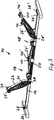
- eine Perspektivansicht eines Ausführungsbeispiels einer erfindungsgemäßen elektromotorisch verstellbaren Stützeinrichtung zum Abstützen einer Boxspring-Matratze mit einem ersten Ausführungsbeispiel eines erfindungsgemäßen Möbelantriebs in Form eines Doppelantriebs, wobei die Stützeinrichtung in der Enlage der Verstellbewegung gezeigt ist, die einer maximal verstellten Position entspricht,
- Fig. 2
- in gleicher Darstellung wie
Fig. 1 die Stützeinrichtung gemäßFig. 1 , wobei Stützteile der Stützeinrichtung weggelassen sind, - Fig. 3
- in gleicher Darstellung wie
Fig. 2 die Stützeinrichtung gemäßFig. 2 , wobei zusätzlich ein Rahmen der Stützeinrichtung weggelassen ist, - Fig. 4
- in gegenüber
Fig. 3 vergrößertem Maßstab eine Einzelheit ausFig. 3 , - Fig. 5
- in gleicher Darstellung wie
Fig. 3 die Stützeinrichtung gemäßFig. 3 , wobei der als Profilschiene ausgebildete Grundkörper des Möbelantriebs weggelassen ist, - Fig. 6
- in vergrößertem Maßstab eine Einzelheit aus
Fig.5 , - Fig. 7
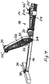
- eine Perspektivansicht eines zweiten Ausführungsbeispiels eines erfindungsgemäßen Doppelantriebs, wobei Schwenkhebel des Doppelantriebs in einer Ausgangslage der Verstellbewegung dargestellt sind,
- Fig. 8
- in gleicher Darstellung wie
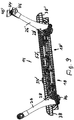
Fig. 7 den Doppelantrieb gemäßFig. 7 , wobei die Schwenkhebel in der Endlage der Verstellbewegung dargestellt sind, - Fig. 9
- in gleicher Darstellung wie
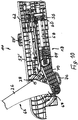
Fig. 8 den Doppelantrieb gemäßFig. 8 , wobei eine Halbschale eines Gehäuses des Doppelantriebs weggelassen ist, - Fig. 10
- in gleicher Darstellung wie
Fig. 9 , jedoch in vergrößertem Maßstab eine Einzelheit ausFig. 9 , - Fig. 11
- in gleicher Darstellung wie
Fig. 10 den Doppelantrieb gemäßFig. 10 , wobei aus Gründen der Veranschaulichung ein Druckstück einer Antriebseinheit des Doppelantriebs weggelassen ist, - Fig. 12:
- in gleicher Darstellung wie
Fig. 10 für sich genommen das Druckstück, - Fig. 13
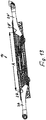
- in gleicher Darstellung wie
Fig. 9 den Doppelantrieb in der inFig. 7 dargestellten Ausgangslage der Verstellbewegung und - Fig. 14
- in gleicher Darstellung wie
Fig. 8 , jedoch in vergrößertem Maßstab eine Einzelheit ausFig. 8 . - Zur Erläuterung eines Ausführungsbeispiels einer erfindungsgemäßen elektromotorisch verstellbaren Stützeinrichtung, die mit einem Ausführungsbeispiel eines elektromotorischen Doppelantriebs versehen ist, wird nachfolgend auf die
Fig. 1 bis 6 Bezug genommen. - In
Fig. 1 ist ein Ausführungsbeispiel einer erfindungsgemäßen elektromotorisch verstellbaren Stützeinrichtung 2 zum Abstützen einer Boxspring-Matratze dargestellt. Die Boxspring-Matratze selbst ist zur Vereinfachung der Darstellung in der Zeichnung nicht gezeigt. - Die Stützeinrichtung 2 weist einen Rahmen 4 und relativ zueinander schwenkverstellbare, plattenfömige Stützteile auf, die ein ortsfestes mittleres Stützteil 6 aufweisen, mit dessen einem Ende gelenkig und um eine horizontale Schwenkachse verschwenkbar ein Oberkörperstützteil 8 verbunden ist. Mit dem dem Oberkörperstützteil 8 abgewandten Ende des mittleren Stützteils 6 ist gelenkig und um eine horizontale Schwenkachse verschwenkbar ein Beinstützteil 10 verbunden, an das ein Wadenstützteil 12 angelenkt ist.
- In
Fig. 2 sind zur Vereinfachung der Darstellung in die Stützteile 6 bis 12 weggelassen. InFig. 3 ist zusätzlich noch der Rahmen 4 der Stützeinrichtung 2 weggelassen - Der Aufbau eines Ausführungsbeispieles eines erfindungsgemäßen Doppelantriebs 14 wird nachfolgend erläutert. Der Doppelantrieb 14 weist einen Grundkörper 16 auf, der bei diesem Ausführungsbeispiel als C-Profilschiene ausgebildet ist. An dem Grundkörper 16 sind zwei Antriebseinheiten 18, 18' angeordnet, wobei die Antriebseinheit 18 dem Oberkörperstützteil 8 zum Verstellen desselben und die Antriebseinheit 18' dem Beinstützteil 10 und dem Wadentützteil 12 zum Verstellen derselben zugeordnet sind. Nachfolgend wird ausschließlich die Antriebseinheit 18 näher erläutert. Die Antriebseinheit 18'ist entsprechend aufgebaut und wird daher hier nicht näher erläutert.
- Die Antriebseinheit 18 weist einen Elektromotor 20 auf, der über ein Schneckengetriebe mit einer Gewindespindel 22 in Drehantriebsverbindung steht, auf der verdrehsicher und in Axialrichtung der Gewindespindel 22 linear beweglich eine Spindelmutter 24 angeordnet ist, die das Abtriebsorgan der Antriebseinheit 18 bildet. Zum Verschwenken des Oberkörperstützteils 8 relativ zu dem mittleren Stützteil 6 ist ein Schwenkelement in Form eines Schwenkhebels 26 vorgesehen, der um eine Schwenkachse 28 schwenkbar an dem Grundkörper 16 des Doppelantriebs 14 gelagert ist. Das der Schwenkachse 28 abgewandte Ende des Schwenkhebels 26 trägt Rollen 30, 30', auf denen sich das Oberkörperstützteil 8 mit seiner der Boxspring-Matratze abgewandten Seite abstützt, so dass der Schwenkhebel 26 das Oberkörperstützteil 8 lose beaufschlagt.
- Mit dem Schwenkhebel 26 ist beabstandet zu dessen Enden gelenkig ein Ende eines Aufstellhebels 32 verbunden, dessen anderes Ende durch die Spindelmutter 24 lose beaufschlagt wird. Ausgehend von einer Ausgangslage der Verstellbewegung, die einer Liegeposition der Stützeinrichtung 2 entspricht und in der das Oberkörperstützteil 8 zusammen mit dem mittleren Stützteil 6 und dem Beinstützteil 10 sowie dem Wadenstüzteil 12 eine im wesentlichen horizontale Stützebene aufspannt, treibt der Elektromotor 20 die Gewindespindel 22 derart an, dass sich die Spindelmutter 24 in der Zeichnung nach rechts bewegt und gegen das zugewandte Ende des Aufstellhebels 32 drückt, wodurch sich der Aufstellhebel 32 aufstellt. Hierdurch wird der Schwenkhebel 26 in der Zeichnung im Uhrzeigersinn verschwenkt, so dass das Oberkörperstützteil in der gewünschten Weise verschwenkt wird.
- Die Rückstellung aus der in der Zeichnung dargestellten Endlage der Verstellbewegung in die Ausgangslage vollzieht sich bei eingeschalteten Elektromotor 20, jedoch unter der Gewichtskraft des Oberkörperstützteils 8 bzw. einer auf der Stützeinrichtung 2 ruhenden Person.
- Wie aus
Fig. 6 ersichtlich ist, weist der Schwenkhebel 26 auf seiner der Spindelmutter 24 und dem Aufstellhebel 32 zugewandten Seite eine in Längsrichtung des Schwenkhebels 26 verlaufende Ausnehmung 34 auf, die so ausgebildet ist, dass in der Ausgangslage der Verstellbewegung, in der das Oberkörperstützteil 8 im wesentlichen horizontal angeordnet ist, die Spindelmutter 24 und der Aufstellhebel 32 in der Ausnehmung 34 aufgenommen sind. - Dadurch, dass der Schwenkhebel 26 schwenkbar an dem Grundkörper 16 des Doppelantriebs 14 gelagert ist, erübrigt sich ein separater Verstellbeschlag. Auf diese Weise ergibt sich ein besonders einfacher Aufbau.
- Erfindungsgemäß ist der Doppelantrieb 14 für eine werkzeuglose Montage an der Stützeinrichtung 2 ausgebildet. Bei dem dargestellten Ausführungsbeispiel weist die Stützeinrichtung 2 quer zu ihrer Längsrichtung verlaufende Streben 36, 36' (vgl. insbesondere
Fig. 2 undFig. 3 ) auf. An den Enden der Profilschiene, die den Grundkörper 16 des Doppelantriebs 14 bildet, sind Auflagerelemente 38, 38' angeordnet, mit denen sich der Grundkörper 16 in der in der Zeichnung dargestellten Montageposition des Doppelantriebs 14 auf den Streben 36, 36' abstützt. Entsprechend den jeweiligen Anforderungen können die Auflagerelemente 38, 38' über geeignete Befestigungsmittel an den Streben 36, 36' befestigt werden. Bei dem dargestellten Ausführungsbeispiel legen die Auflagerelemente 38, 38' jedoch lose auf den Streben 36, 36' auf. Der Abstand zwischen voneinander weg weisenden vertikalen Flächen der Auflagerelemente 38, 38' entspricht dabei im wesentlichen der lichten Weite zwischen den Querstreben 36, 36'. Ggf. kann der Doppelantrieb 14 hierbei leicht klemmend zwischen den Querstreben 36, 36'gehalten sein. - Bei dem dargestellten Ausführungsbeispiel sind ferner Befestigungsmittel zur werkzeuglosen Befestigung des mittleren Stützteils 6 an dem Grundkörper 16 des Doppelantriebs 14 vorgesehen, die bei diesem Ausführungsbeispiel eine werkzeuglos handbetätigbare Schraubvorrichtung aufweisen. Die Schraubvorrichtung weist bei dem dargestellten Ausführungsbeispiel im Sinne einer werkzeuglosen Befestigung sind Flügelschrauben auf, von denen in
Fig. 6 lediglich eine Flügelschraube 42 erkennbar ist. Die Flügelschrauben sind in an dem mittleren Stützteil 6 angeordnete Muttern 40, 40' einschraubbar. - Zur Demontage des Doppelantriebs 14, beispielsweise zu Wartungszwecken, ist es lediglich erforderlich, die Flügelschrauben 42, 42' zu lösen und die Auflagerelemente 38, 38' von den Streben 36, 36' abzuheben. Die Montage und Demontage des Doppelantriebs 14 sind damit völlig werkzeuglos und besonders einfach zu bewerkstelligen.
- Der dem Beinstützteil 10 und dem Wadenstützteil 12 zugeordnete Schwenkhebel 26' trägt an seinen Enden eine parallel zu der Schwenkachse des Schwenkhebels 26' verlaufende Achse 44 (vgl.
Fig. 3 ), die in Montageposition des Doppelantriebs 14 in Aufnahmen 46, 46' aufgenommen ist, die an der Unterseite des Wadenstützteils 12 befestigt sind. Auf diese Weise werden beim Verschwenken des Schwenkhebels 26 das Beinstützteil 10 und das Wadenstützteil 14 verstellt. - Eigenständige erfinderische Bedeutung hat auch ein Verfahren zur Notabsenkung eines mittels eines erfindungsgemäßen Möbelantriebs verstellten Stützteiles. Fällt beispielsweise in der in
Fig. 6 dargestellten Verstelllage des Schwenkhebels 26 und damit des Oberkörperstützteils 8 der Strom aus, so kann der Schwenkhebel 26 von Hand inFig. 6 im Uhrzeigersinn bewegt werden, so dass der Aufstellhebel 32 außer Eingriff von der Spindelmutter 24 kommt und der Schwenkhebel 26 damit von den Antriebsstrang der Antriebseinheit 18 entkoppelt ist. Daran anschließend kann der Schwenkhebel 26 in der Zeichnung entgegen dem Uhrzeigersinn bewegt werden, wobei sich das Oberkörperstützteil zurück in die Ausgangslage bewegt und der Aufstellhebel 32 über die Spindelmutter 24 in der Zeichnung nach links hinweg gleitet. In der am Ende dieser Bewegung wieder erreichten Ausgangslage der Verstellbewegung sind der Aufstellhebel 32 und die Spindelmutter 24 in der Ausnehmung 34 des Schwenkhebels 26 aufgenommen. - Um den Schwenkhebel 26 wieder in Antriebsverbindung mit dem Antriebsstrang der Antriebseinheit 18 zu bringen, ist es lediglich erforderlich, den Elektromotor 20 so anzusteuern, dass die Spindelmutter 24 in der Zeichnung nach links zurück in ihre Ausgangslage fährt. Dabei unterfährt sie den Aufstellhebel 32, so dass dieser über die Spindelmutter 24 hinweggleitet und wieder in Eingriff mit dem dem Elektromotor 20 zugewandten Ende der Spindelmutter 24 kommt und die Antriebsverbindung somit wieder hergestellt ist. Um diesen Vorgang zu erleichtern, kann der Aufstellhebel 32 an der Unterseite seines freien Endes mit einer Anlaufschräge 46 versehen sein, wie aus
Fig. 6 ersichtlich.Die Notabsenkung ist damit besonders einfach gestaltet. - Zur Erläuterung eines zweiten Ausführungsbeispiels eines erfindungsgemäßen Möbelantriebs wird nachfolgend auf die
Figuren 7 bis 14 Bezug genommen. - In
Fig. 7 ist ein zweites Ausführungsbeispiel eines erfindungsgemäßen Doppelantriebs 14 dargestellt, an dessen Grundkörper 16 in Übereinstimmung mit dem ersten Ausführungsbeispiel Schwenkelemente in Form von Schwenkhebeln 26, 26 jeweils um eine Schwenkachse 28, 28' schwenkbar gelagert befestigt sind. In weiterer Übereinstimmung mit dem ersten Ausführungsbeispiel ist der Doppelantrieb 14 für eine werkzeuglose Montage an einer Stützeinrichtung für eine Boxspring-Matratze oder ein Polsterbett ausgebildet, wie dies für das erste Ausführungsbeispiel erläutert worden ist.Fig. 7 zeigt den Doppelantrieb 14 in einer Ausgangslage der Verstellbewegung mit einer Position der Schwenkhebel 26, 26, die einer Verstelllage der Stützeinrichtung entspricht, in der die Stützteile eine im Wesentlichen horizontale Stützebene aufspannen. -
Fig. 8 zeigt den Doppelantrieb gemäßFig. 7 in einer Position der Schwenkhebel 26, 26', die einer Endlage der Verstellbewegung entspricht, in der die Stützteile relativ zueinander maximal verstellt sind. - Das zweite Ausführungsbeispiel unterscheidet sich von dem ersten Ausführungsbeispiel zunächst dadurch, dass der Grundkörper 16 als Gehäuse 50 ausgebildet ist, in dem die den Schwenkhebeln 26, 26' zugeordneten Antriebseinheiten aufgenommen sind. Das Gehäuse 50 besteht bei dem dargestellten Ausführungsbeispiel aus zwei Halbschalen 52, 52' aus Kunststoff. Die Halbschalen 52, 52' sind miteinander schraubverbunden bzw. schraubverbindbar.
- An den in Längsrichtung gelegenen Enden des Gehäuses 50 sind Auflagerelemente 38, 38' in das Gehäuse eingeformt, mit denen der Doppelantrieb 14 in Montageposition auf quer verlaufenden Streben einer Stützeinrichtung aufliegt und sich an diesen abstützt (vgl. die Bezugszeichen 36, 36' in
Fig. 3 ). - Zur Befestigung an einem ortsfesten mittleren Stützteil einer Stützeinrichtung sind an die Halbschalen 52, 52' Befestigungslaschen 54, 54' angeformt, wie in
Fig. 8 und besonders gut inFig. 14 erkennbar. - Die Montage des Doppelantriebs 14 an einer Stützeinrichtung vollzieht sich prinzipiell in der gleichen Art und Weise wie in Bezug auf das erste Ausführungsbeispiel erläutert. Hierzu wird der Doppelantrieb 14 mittels der Auflagerelemente 38, 38' auf die quer verlaufenden Streben der Stützeinrichtung aufgelegt. Daran anschließend kann der Doppelantrieb 14 über die Befestigungslaschen 54, 54' mit seinem Gehäuse mit einem ortsfesten mittleren Stützteil einer Stützeinrichtung verschraubt werden. Die Verschraubung kann insbesondere über eine werkzeuglos betätigbare Schraubvorrichtung hergestellt werden.
- Anhand der
Figuren 9 bis 12 werden nachfolgend die Antriebseinheiten 18, 18' des Doppelantriebs 14 näher erläutert. -
Fig. 9 zeigt den Doppelantrieb 14 in der Verstelllage entsprechendFig. 1 , wobei aus Gründen der Erläuterung des Aufbaus der Antriebseinheiten 18, 18' die Halbschale 52 des Gehäuses 16 weggelassen ist. Nachfolgend wird ausschließlich die Antriebseinheit 18 näher erläutert, die Antriebseinheit 18' ist entsprechend aufgebaut und wird daher nicht näher erläutert. - Die Antriebseinheit 18 weist eine drehbar in dem Gehäuse 16 gelagerte, ortsfeste Spindelmutter 56 auf, die auf eine in dem Gehäuse 16 verdrehsicher gelagerte und in ihrer Axialrichtung bewegliche Gewindespindel 58 aufgesetzt ist. Mit der Spindelmutter 56 ist drehfest ein Schneckenrad 60 verbunden, das mit einer Schnecke 62 in Eingriff steht, die mit der Antriebswelle eines Elektromotors der Antriebseinheit 18 in Eingriff steht, so dass sich die Gewindespindel 58 entsprechend der Drehrichtung der Antriebswelle des Elektromotors in
Fig. 10 nach links oder rechts bewegt. - Zur Spannungsversorgung und Ansteuerung der Antriebseinheiten 18, 18' sind in der Zeichnung nicht näher dargestellte Spannungsversorgungs- und Ansteuerungsmittel vorgesehen, deren grundsätzlicher Aufbau dem Fachmann jedoch allgemein bekannt ist und daher hier nicht näher erläutert wird.
- Auf das der Schwenkachse 28 zugewandte Ende der Gewindespindel 58 ist ein Druckstück 64 aufgesetzt.
- Abweichend von dem ersten Ausführungsbeispiel ist bei dem zweiten Ausführungsbeispiel der Schwenkhebel 26 als zweiarmiger Hebel ausgebildet, dessen erster Hebelarm 66 das zugeordnete zu verstellende Stützteil lose beaufschlagt und dessen zweiter Hebelarm 68 mit dem durch das Druckstück 64 gebildete Antriebsorgan der Antriebseinheit 18 in Antriebsverbindung steht.
- Zwischen dem zweiten Hebelarm 68 und dem Druckstück 64 der Antriebseinheit 18 ist eine Lasche 70 angeordnet, deren erstes Ende entfernt zu der Schwenkachse 28 gelenkig mit dem zweiten Hebelarm 68 verbunden ist und deren zweites Ende von dem Druckstück 64 druckbeaufschlagbar ist bzw. während der Verstellbewegung druckbeaufschlagt wird. Bei dem dargestellten Ausführungsbeispiel beaufschlagt das Druckstück das zweite Ende der Lasche 70 mittels einer Eingriffsfläche lose.
-
Fig. 11 zeigt die Antriebseinheit 18, wobei zur Erläuterung das Druckstück 64 weggelassen ist. -
Fig. 12 zeigt das Druckstück 64 für sich genommen, wobei insbesondere eine Eingriffsfläche 72 des Druckstücks 64 erkennbar ist. - Aus
Fig. 11 undFig. 12 sowie einem Vergleich vonFig. 11 mitFig. 12 ist ersichtlich, dass die Eingriffsfläche 72 und das zweite Ende der Lasche in Querschnitt profiliert und zueinander komplementär geformt sind. Bei dem dargestellten Ausführungsbeispiel ist die Eingriffsfläche 64 im Querschnitt konkav und das zweite Ende der Lasche entsprechend komplementär konvex geformt, wobei die Eingriffsfläche 72 und das Ende der Lasche 70 im Querschnitt kreisbogenförmig ausgebildet sind. - Zum Vorspannen des zweiten Endes der Lasche 70 gegen die Eingriffsfläche 72 des Druckstücks 64 sind Federmittel vorgesehen, die bei diesem Ausführungsbeispiel zwischen einer Innenwandung des Gehäuses 50 und der Lasche 70 wirkende Zugfeder in Form einer Schraubenfeder 74 gebildet sind.
- Zum Verstellen des Schwenkhebels 26 und damit des zugeordneten Stützteiles aus der in
Fig. 7 dargestellten Ausgangslage der Verstellbewegung in Richtung auf die inFig. 8 dargestellte Endlage der Verstellbewegung treibt der Elektromotor die Spindelmutter 56 derart an, dass sich die Gewindespindel 58 mit dem Druckstück 64 inFig. 10 nach links bewegt. Hierbei drückt das Druckstück 64 gegen das zweite Ende der Lasche 70. Mittels der Schraubenfeder 74 ist dabei das zweite Ende der Lasche 70 in Eingriff mit der Eingriffsfläche 72 gehalten. Während der Bewegung des Druckstücks 64 inFig. 10 nach links verschwenkt der Schwenkhebel 26 inFig. 10 im Uhrzeigersinn, so dass in der gewünschten Weise das von dem Schwenkhebel 26 beaufschlagte Stützteil verschwenkt wird. - Falls bei verstellter Stützeinrichtung der Strom ausfällt, kann der Schwenkhebel 26 mit dem dadurch verstellten Stützteil im Sinne einer Notausrückung (Notabsenkung) wie folgt von Hand zurückgestellt werden:
- Zum Durchführen einer Notabsenkung wird der Schwenkhebel 26 über die in
Fig. 10 dargestellte Endlage der Verstellbewegung hinaus von Hand inFig. 10 im Uhrzeigersinn bewegt, wobei das zweite Ende der Lasche 70 von der Eingriffsfläche 72 des Druckstücks 64 außer Eingriff kommt. Durch die Schraubenfeder 74 wird hierbei die Lasche 70 nach oben gezogen. - Die Lasche 70 ist an ihrem unteren Ende mit einem Griffelement 76 versehen, das durch eine in dem Gehäuse 50 gebildete Öffnung zugänglich ist, wie dies aus
Fig. 8 ersichtlich ist. Mittels des Griffelementes 76 kann die Lasche 70 nach unten gezogen und aus der Bewegungsbahn des Druckstücks 64 herausbewegt werden. Daran anschließend kann der Schwenkhebel mit dem dadurch verstellten Stützteil inFig. 10 entgegen dem Uhrzeigersinn zurückverstellt werden, wobei sich die Lasche 70 außerhalb des Gehäuses 50 unter das stillgesetzte Druckstück bewegt. - Um die Lasche 70 wieder in Eingriff mit der Eingriffsfläche 72 zu bringen und die Antriebseinheit 18 damit wieder zu aktivieren, kann der Schwenkhebel 26 von Hand in
Fig. 10 im Uhrzeigersinn bewegt werden, wobei die Lasche 70 unter der Wirkung der Schraubenfeder 74 wieder in Eingriff mit der Eingriffsfläche 72 des Druckstücks 64 gelangt. - Auf diese Weise ist eine Notabsenkung realisiert, die für sich genommen eine eigenständige erfinderische Bedeutung hat.
- In
Fig. 13 ist der Abstand der Schwenkachsen 28, 28' zueinander mit "A" gekennzeichnet. Gemäß einer Ausführungsform der Erfindung, die für sich genommen bei Doppelantrieben jeglicher Art eine eigenständige erfinderische Bedeutung besitzt, ist der Abstand "A" größer als 620 mm. Auf diese Weise ergeben sich bei der Verstellung von Stützteilen einer Stützeinrichtung besonders günstige Verhältnisse.
Claims (14)
- Elektromotorischer Doppelantrieb (14) für eine verstellbare Stützeinrichtung (2) zum Abstützen einer Boxspring-Matratze oder eines Polsterbetts , die einen Rahmen (4) und relativ zueinander schwenkverstellbare, plattenfömige Stützteile (6-12) aufweist, die wenigstens ein ortsfestes mittleres Stützteil aufweisen, mit dessen einem Ende gelenkig und um eine horizontale Schwenkachse verschwenkbar ein Oberkörperstützteil (8) und mit dessen anderem Ende gelenkig und um eine horizontale Schwenkachse verschwenkbar ein Beinstützteil (10) verbunden ist,
wobei der Doppelantrieb (14) einen Grundkörper (16) aufweist, an dem zwei Antriebseinheiten (18, 18') angeordnet sind, wobei jede Antriebseinheit (18, 18') in Montageposition des Doppelantriebs (14) mit einem Schwenkhebel (26, 26') antriebstechnisch verbunden ist,
wobei die Schwenkhebel (26, 26') schwenkbar gelagert an dem Grundkörper befestigt sind und jeweils mit einem zu verstellenden Stützteil in Wirkungsverbindung stehen zum Verstellen desselben und
wobei der Doppelantrieb (14) für eine werkzeuglose Montage an der Stützeinrichtung (2) ausgebildet ist. - Doppelantrieb nach Anspruch 1, wobei wenigstens ein Schwenkhebel (26) in Montageposition des Doppelantriebs (14) das zugeordnete Stützteil lose beaufschlagt.
- Möbelantrieb nach Anspruch 1 oder 2, wobei jeder Schwenkhebel (26, 26) mittels eines zugeordneten Abtriebsorganes zum Verschwenken des zugeordneten Stützteiles verschwenkbar ist.
- Möbelantrieb nach Anspruch 3, wobei das oder jedes Abtriebsorgan linear beweglich ist.
- Möbelantrieb nach Anspruch 4, wobei das Abtriebsorgan eine Spindelmutter (24) ist, die verdrehsicher und in Axialrichtung beweglich auf einer Gewindespindel (22) angeordnet ist, die in Drehantriebsverbindung mit einem Elektromotor (20) der Antriebseinheit steht,
- Doppelantrieb nach Anspruch 4, wobei das Abtriebsorgan eine Gewindespindel ist, die verdrehsicher und in ihrer Axialrichtung beweglich gelagert ist und auf der eine ortsfeste Spindelmutter angeordnet ist, die in Drehantriebsverbindung mit einem Elektromotor der Antriebseinheit steht.
- Doppelantrieb nach einem der vorhergehenden Ansprüche, wobei der Grundkörper (16) des Doppelantriebs (14) als Gehäuse (50), vorzugsweise aus Kunststoff, ausgebildet ist.
- Doppelantrieb nach Anspruch 7, dadurch gekennzeichnet wobei das Gehäuse (50) aus zwei Halbschalen (52, 52') besteht.
- Doppelantrieb nach einem der vorhergehenden Ansprüche, bei dem an den Enden des Grundkörpers (16) Auflagerelemente gebildet sind, mit denen der Grundkörper (16) in Montageposition des Doppelantriebs (14) auf quer verlaufenden Streben (36, 36') der Stützeinrichtung (2) aufliegt.
- Doppelantrieb nach Anspruch 9, dadurch gekennzeichnet, dass die Auflagerelemente (38, 38') in Montageposition des Doppelantriebs (14) lose auf den Streben (36, 36') aufliegen.
- Doppelantrieb nach einem der vorhergehenden Ansprüche, wobei Befestigungsmittel zur werkzeuglosen Befestigung des mittleren Stützteils (6) an dem Grundkörper (16) des Doppelantriebs (14) vorgesehen sind.
- Doppelantrieb nach Anspruch 11, wobei die Befestigungsmittel eine werkzeuglos handbetätigbare Schraubvorrichtung aufweisen.
- Doppelantrieb nach einem der vorhergehenden Ansprüche, wobei an den Grundkörper (16) Befestigungslaschen (54, 54') zur Schraubbefestigung des Grundkörpers (16) an dem ortsfesten mittleren Stützteil angeformt sind oder an dem Grundkörper (16) ausgebildet sind.
- Elektromotorisch verstellbare Stützeinrichtung zum Abstützen einer Boxspring-Matratze oder eines Polsterbetts, die einen einem Doppelantrieb nach einem der vorhergehenden Ansprüche aufweist.
Applications Claiming Priority (3)
| Application Number | Priority Date | Filing Date | Title |
|---|---|---|---|
| DE102016108033 | 2016-04-29 | ||
| DE102016113980 | 2016-07-28 | ||
| DE102016116250.7A DE102016116250A1 (de) | 2016-04-29 | 2016-08-31 | Elektromotorischer Doppelantrieb |
Publications (3)
| Publication Number | Publication Date |
|---|---|
| EP3238573A2 true EP3238573A2 (de) | 2017-11-01 |
| EP3238573A3 EP3238573A3 (de) | 2018-02-14 |
| EP3238573B1 EP3238573B1 (de) | 2019-06-12 |
Family
ID=58579070
Family Applications (1)
| Application Number | Title | Priority Date | Filing Date |
|---|---|---|---|
| EP17167278.5A Active EP3238573B1 (de) | 2016-04-29 | 2017-04-20 | Elektromotorischer doppelantrieb |
Country Status (1)
| Country | Link |
|---|---|
| EP (1) | EP3238573B1 (de) |
Cited By (2)
| Publication number | Priority date | Publication date | Assignee | Title |
|---|---|---|---|---|
| DE202022101259U1 (de) | 2022-03-08 | 2023-06-14 | De Werth Group Ag | Boxspring-Bett |
| DE102022105381A1 (de) | 2022-03-08 | 2023-09-14 | De Werth Group Ag | Boxspring-Bett |
Family Cites Families (4)
| Publication number | Priority date | Publication date | Assignee | Title |
|---|---|---|---|---|
| US5063623A (en) * | 1990-10-15 | 1991-11-12 | Bathrick Leeland M | Power module for an ariculated bed |
| US5537701A (en) * | 1994-03-15 | 1996-07-23 | Maxwell Products, Inc. | Adjustable articulated bed |
| US6990698B2 (en) * | 2004-05-12 | 2006-01-31 | Wall Sr Daniel P | UPS shippable adjustable articulating bed |
| US8935817B2 (en) * | 2013-06-17 | 2015-01-20 | Pragma Corporation | Motorized foldable bed frame assembly |
-
2017
- 2017-04-20 EP EP17167278.5A patent/EP3238573B1/de active Active
Non-Patent Citations (1)
| Title |
|---|
| None |
Cited By (2)
| Publication number | Priority date | Publication date | Assignee | Title |
|---|---|---|---|---|
| DE202022101259U1 (de) | 2022-03-08 | 2023-06-14 | De Werth Group Ag | Boxspring-Bett |
| DE102022105381A1 (de) | 2022-03-08 | 2023-09-14 | De Werth Group Ag | Boxspring-Bett |
Also Published As
| Publication number | Publication date |
|---|---|
| EP3238573B1 (de) | 2019-06-12 |
| EP3238573A3 (de) | 2018-02-14 |
Similar Documents
| Publication | Publication Date | Title |
|---|---|---|
| DE102016116253A1 (de) | Elektromotorischer Doppelantrieb | |
| EP2792277B1 (de) | Elektromotorischer möbelantrieb | |
| EP1410743B1 (de) | Motorisch verstellbare Stützeinrichtung für eine Polsterung eines Sitz- und/oder Liegemöbels, beispielsweise einer Matratze oder eines Bettes | |
| DE102004016048A1 (de) | Baukastensystem zur Montage motorisch verstellbarer Stützeinrichtungen zur Polsterung von Sitz- und/oder Liegemöbel | |
| EP2974622A1 (de) | Elektromotorisch verstellbare stützeinrichtung | |
| EP1603433A1 (de) | Baukastensystem zur montage motorisch verstellbarer stützeinrichtungen zur polsterung von sitz- und/oder liegemöbeln | |
| DE102014115033A1 (de) | Elektromotorisch verstellbare Stützeinrichtung | |
| DE102020131206A1 (de) | Elektromotorisch verstellbare Stützeinrichtung | |
| EP3491973A1 (de) | Elektromotorisch verstellbare stützeinrichtung | |
| DE202013007106U1 (de) | Möbelantrieb | |
| EP3157389A1 (de) | Elektromotorischer möbelantrieb | |
| EP3238573B1 (de) | Elektromotorischer doppelantrieb | |
| DE102016116255A1 (de) | Elektromotorischer Möbelantrieb | |
| WO2005104903A1 (de) | Baukastensystem zur montage motorisch verstellbarer stützeinrichtungen für polsterungen von sitz- und/oder liegemöbeln | |
| DE102020131204A1 (de) | Elektromotorisch verstellbare Stützeinrichtung | |
| EP3238574B1 (de) | Elektromotorischer doppelantrieb | |
| DE102014115084A1 (de) | Möbelantrieb | |
| DE102022111839A1 (de) | Elektromotorisch verstellbare Stützeinrichtung | |
| DE202021101529U1 (de) | Antrieb für einen Lattenrost und Bausatz zum Nachrüsten eines manuell verstellbaren Lattenrosts mit diesem Antrieb | |
| DE102016116252A1 (de) | Elektromotorischer Möbelantrieb | |
| EP4458219A1 (de) | Elektromotorischer doppelantrieb | |
| DE202025102777U1 (de) | Verstellbarer Lattenrost | |
| DE202022101259U1 (de) | Boxspring-Bett | |
| DE202019103303U1 (de) | Elektromotorischer Möbelantrieb | |
| DE102021102440A1 (de) | Elektromotorische Verstellvorrichtung |
Legal Events
| Date | Code | Title | Description |
|---|---|---|---|
| PUAI | Public reference made under article 153(3) epc to a published international application that has entered the european phase |
Free format text: ORIGINAL CODE: 0009012 |
|
| STAA | Information on the status of an ep patent application or granted ep patent |
Free format text: STATUS: THE APPLICATION HAS BEEN PUBLISHED |
|
| AK | Designated contracting states |
Kind code of ref document: A2 Designated state(s): AL AT BE BG CH CY CZ DE DK EE ES FI FR GB GR HR HU IE IS IT LI LT LU LV MC MK MT NL NO PL PT RO RS SE SI SK SM TR |
|
| AX | Request for extension of the european patent |
Extension state: BA ME |
|
| PUAL | Search report despatched |
Free format text: ORIGINAL CODE: 0009013 |
|
| AK | Designated contracting states |
Kind code of ref document: A3 Designated state(s): AL AT BE BG CH CY CZ DE DK EE ES FI FR GB GR HR HU IE IS IT LI LT LU LV MC MK MT NL NO PL PT RO RS SE SI SK SM TR |
|
| AX | Request for extension of the european patent |
Extension state: BA ME |
|
| RIC1 | Information provided on ipc code assigned before grant |
Ipc: A47C 20/04 20060101AFI20180109BHEP |
|
| STAA | Information on the status of an ep patent application or granted ep patent |
Free format text: STATUS: REQUEST FOR EXAMINATION WAS MADE |
|
| 17P | Request for examination filed |
Effective date: 20180814 |
|
| RBV | Designated contracting states (corrected) |
Designated state(s): AL AT BE BG CH CY CZ DE DK EE ES FI FR GB GR HR HU IE IS IT LI LT LU LV MC MK MT NL NO PL PT RO RS SE SI SK SM TR |
|
| GRAP | Despatch of communication of intention to grant a patent |
Free format text: ORIGINAL CODE: EPIDOSNIGR1 |
|
| STAA | Information on the status of an ep patent application or granted ep patent |
Free format text: STATUS: GRANT OF PATENT IS INTENDED |
|
| INTG | Intention to grant announced |
Effective date: 20181212 |
|
| GRAS | Grant fee paid |
Free format text: ORIGINAL CODE: EPIDOSNIGR3 |
|
| GRAA | (expected) grant |
Free format text: ORIGINAL CODE: 0009210 |
|
| STAA | Information on the status of an ep patent application or granted ep patent |
Free format text: STATUS: THE PATENT HAS BEEN GRANTED |
|
| AK | Designated contracting states |
Kind code of ref document: B1 Designated state(s): AL AT BE BG CH CY CZ DE DK EE ES FI FR GB GR HR HU IE IS IT LI LT LU LV MC MK MT NL NO PL PT RO RS SE SI SK SM TR |
|
| REG | Reference to a national code |
Ref country code: GB Ref legal event code: FG4D Free format text: NOT ENGLISH |
|
| REG | Reference to a national code |
Ref country code: CH Ref legal event code: EP |
|
| REG | Reference to a national code |
Ref country code: AT Ref legal event code: REF Ref document number: 1141440 Country of ref document: AT Kind code of ref document: T Effective date: 20190615 |
|
| REG | Reference to a national code |
Ref country code: DE Ref legal event code: R096 Ref document number: 502017001516 Country of ref document: DE |
|
| REG | Reference to a national code |
Ref country code: IE Ref legal event code: FG4D Free format text: LANGUAGE OF EP DOCUMENT: GERMAN |
|
| REG | Reference to a national code |
Ref country code: NL Ref legal event code: MP Effective date: 20190612 |
|
| REG | Reference to a national code |
Ref country code: LT Ref legal event code: MG4D |
|
| PG25 | Lapsed in a contracting state [announced via postgrant information from national office to epo] |
Ref country code: NO Free format text: LAPSE BECAUSE OF FAILURE TO SUBMIT A TRANSLATION OF THE DESCRIPTION OR TO PAY THE FEE WITHIN THE PRESCRIBED TIME-LIMIT Effective date: 20190912 Ref country code: FI Free format text: LAPSE BECAUSE OF FAILURE TO SUBMIT A TRANSLATION OF THE DESCRIPTION OR TO PAY THE FEE WITHIN THE PRESCRIBED TIME-LIMIT Effective date: 20190612 Ref country code: LT Free format text: LAPSE BECAUSE OF FAILURE TO SUBMIT A TRANSLATION OF THE DESCRIPTION OR TO PAY THE FEE WITHIN THE PRESCRIBED TIME-LIMIT Effective date: 20190612 Ref country code: AL Free format text: LAPSE BECAUSE OF FAILURE TO SUBMIT A TRANSLATION OF THE DESCRIPTION OR TO PAY THE FEE WITHIN THE PRESCRIBED TIME-LIMIT Effective date: 20190612 Ref country code: HR Free format text: LAPSE BECAUSE OF FAILURE TO SUBMIT A TRANSLATION OF THE DESCRIPTION OR TO PAY THE FEE WITHIN THE PRESCRIBED TIME-LIMIT Effective date: 20190612 Ref country code: SE Free format text: LAPSE BECAUSE OF FAILURE TO SUBMIT A TRANSLATION OF THE DESCRIPTION OR TO PAY THE FEE WITHIN THE PRESCRIBED TIME-LIMIT Effective date: 20190612 |
|
| PG25 | Lapsed in a contracting state [announced via postgrant information from national office to epo] |
Ref country code: GR Free format text: LAPSE BECAUSE OF FAILURE TO SUBMIT A TRANSLATION OF THE DESCRIPTION OR TO PAY THE FEE WITHIN THE PRESCRIBED TIME-LIMIT Effective date: 20190913 Ref country code: LV Free format text: LAPSE BECAUSE OF FAILURE TO SUBMIT A TRANSLATION OF THE DESCRIPTION OR TO PAY THE FEE WITHIN THE PRESCRIBED TIME-LIMIT Effective date: 20190612 Ref country code: RS Free format text: LAPSE BECAUSE OF FAILURE TO SUBMIT A TRANSLATION OF THE DESCRIPTION OR TO PAY THE FEE WITHIN THE PRESCRIBED TIME-LIMIT Effective date: 20190612 Ref country code: BG Free format text: LAPSE BECAUSE OF FAILURE TO SUBMIT A TRANSLATION OF THE DESCRIPTION OR TO PAY THE FEE WITHIN THE PRESCRIBED TIME-LIMIT Effective date: 20190912 |
|
| PG25 | Lapsed in a contracting state [announced via postgrant information from national office to epo] |
Ref country code: RO Free format text: LAPSE BECAUSE OF FAILURE TO SUBMIT A TRANSLATION OF THE DESCRIPTION OR TO PAY THE FEE WITHIN THE PRESCRIBED TIME-LIMIT Effective date: 20190612 Ref country code: SK Free format text: LAPSE BECAUSE OF FAILURE TO SUBMIT A TRANSLATION OF THE DESCRIPTION OR TO PAY THE FEE WITHIN THE PRESCRIBED TIME-LIMIT Effective date: 20190612 Ref country code: NL Free format text: LAPSE BECAUSE OF FAILURE TO SUBMIT A TRANSLATION OF THE DESCRIPTION OR TO PAY THE FEE WITHIN THE PRESCRIBED TIME-LIMIT Effective date: 20190612 Ref country code: CZ Free format text: LAPSE BECAUSE OF FAILURE TO SUBMIT A TRANSLATION OF THE DESCRIPTION OR TO PAY THE FEE WITHIN THE PRESCRIBED TIME-LIMIT Effective date: 20190612 Ref country code: PT Free format text: LAPSE BECAUSE OF FAILURE TO SUBMIT A TRANSLATION OF THE DESCRIPTION OR TO PAY THE FEE WITHIN THE PRESCRIBED TIME-LIMIT Effective date: 20191014 Ref country code: EE Free format text: LAPSE BECAUSE OF FAILURE TO SUBMIT A TRANSLATION OF THE DESCRIPTION OR TO PAY THE FEE WITHIN THE PRESCRIBED TIME-LIMIT Effective date: 20190612 |
|
| PG25 | Lapsed in a contracting state [announced via postgrant information from national office to epo] |
Ref country code: IT Free format text: LAPSE BECAUSE OF FAILURE TO SUBMIT A TRANSLATION OF THE DESCRIPTION OR TO PAY THE FEE WITHIN THE PRESCRIBED TIME-LIMIT Effective date: 20190612 Ref country code: IS Free format text: LAPSE BECAUSE OF FAILURE TO SUBMIT A TRANSLATION OF THE DESCRIPTION OR TO PAY THE FEE WITHIN THE PRESCRIBED TIME-LIMIT Effective date: 20191012 Ref country code: SM Free format text: LAPSE BECAUSE OF FAILURE TO SUBMIT A TRANSLATION OF THE DESCRIPTION OR TO PAY THE FEE WITHIN THE PRESCRIBED TIME-LIMIT Effective date: 20190612 |
|
| REG | Reference to a national code |
Ref country code: DE Ref legal event code: R097 Ref document number: 502017001516 Country of ref document: DE |
|
| PG25 | Lapsed in a contracting state [announced via postgrant information from national office to epo] |
Ref country code: TR Free format text: LAPSE BECAUSE OF FAILURE TO SUBMIT A TRANSLATION OF THE DESCRIPTION OR TO PAY THE FEE WITHIN THE PRESCRIBED TIME-LIMIT Effective date: 20190612 |
|
| PLBE | No opposition filed within time limit |
Free format text: ORIGINAL CODE: 0009261 |
|
| STAA | Information on the status of an ep patent application or granted ep patent |
Free format text: STATUS: NO OPPOSITION FILED WITHIN TIME LIMIT |
|
| PG25 | Lapsed in a contracting state [announced via postgrant information from national office to epo] |
Ref country code: DK Free format text: LAPSE BECAUSE OF FAILURE TO SUBMIT A TRANSLATION OF THE DESCRIPTION OR TO PAY THE FEE WITHIN THE PRESCRIBED TIME-LIMIT Effective date: 20190612 Ref country code: PL Free format text: LAPSE BECAUSE OF FAILURE TO SUBMIT A TRANSLATION OF THE DESCRIPTION OR TO PAY THE FEE WITHIN THE PRESCRIBED TIME-LIMIT Effective date: 20190612 |
|
| 26N | No opposition filed |
Effective date: 20200313 |
|
| PG25 | Lapsed in a contracting state [announced via postgrant information from national office to epo] |
Ref country code: SI Free format text: LAPSE BECAUSE OF FAILURE TO SUBMIT A TRANSLATION OF THE DESCRIPTION OR TO PAY THE FEE WITHIN THE PRESCRIBED TIME-LIMIT Effective date: 20190612 Ref country code: IS Free format text: LAPSE BECAUSE OF FAILURE TO SUBMIT A TRANSLATION OF THE DESCRIPTION OR TO PAY THE FEE WITHIN THE PRESCRIBED TIME-LIMIT Effective date: 20200224 |
|
| PG2D | Information on lapse in contracting state deleted |
Ref country code: IS |
|
| PG25 | Lapsed in a contracting state [announced via postgrant information from national office to epo] |
Ref country code: ES Free format text: LAPSE BECAUSE OF FAILURE TO SUBMIT A TRANSLATION OF THE DESCRIPTION OR TO PAY THE FEE WITHIN THE PRESCRIBED TIME-LIMIT Effective date: 20190612 |
|
| PG25 | Lapsed in a contracting state [announced via postgrant information from national office to epo] |
Ref country code: MC Free format text: LAPSE BECAUSE OF FAILURE TO SUBMIT A TRANSLATION OF THE DESCRIPTION OR TO PAY THE FEE WITHIN THE PRESCRIBED TIME-LIMIT Effective date: 20190612 |
|
| REG | Reference to a national code |
Ref country code: CH Ref legal event code: PL |
|
| PG25 | Lapsed in a contracting state [announced via postgrant information from national office to epo] |
Ref country code: LI Free format text: LAPSE BECAUSE OF NON-PAYMENT OF DUE FEES Effective date: 20200430 Ref country code: LU Free format text: LAPSE BECAUSE OF NON-PAYMENT OF DUE FEES Effective date: 20200420 Ref country code: CH Free format text: LAPSE BECAUSE OF NON-PAYMENT OF DUE FEES Effective date: 20200430 Ref country code: FR Free format text: LAPSE BECAUSE OF NON-PAYMENT OF DUE FEES Effective date: 20200430 |
|
| REG | Reference to a national code |
Ref country code: BE Ref legal event code: MM Effective date: 20200430 |
|
| PG25 | Lapsed in a contracting state [announced via postgrant information from national office to epo] |
Ref country code: BE Free format text: LAPSE BECAUSE OF NON-PAYMENT OF DUE FEES Effective date: 20200430 |
|
| PG25 | Lapsed in a contracting state [announced via postgrant information from national office to epo] |
Ref country code: IE Free format text: LAPSE BECAUSE OF NON-PAYMENT OF DUE FEES Effective date: 20200420 |
|
| GBPC | Gb: european patent ceased through non-payment of renewal fee |
Effective date: 20210420 |
|
| PG25 | Lapsed in a contracting state [announced via postgrant information from national office to epo] |
Ref country code: GB Free format text: LAPSE BECAUSE OF NON-PAYMENT OF DUE FEES Effective date: 20210420 |
|
| PG25 | Lapsed in a contracting state [announced via postgrant information from national office to epo] |
Ref country code: MT Free format text: LAPSE BECAUSE OF FAILURE TO SUBMIT A TRANSLATION OF THE DESCRIPTION OR TO PAY THE FEE WITHIN THE PRESCRIBED TIME-LIMIT Effective date: 20190612 Ref country code: CY Free format text: LAPSE BECAUSE OF FAILURE TO SUBMIT A TRANSLATION OF THE DESCRIPTION OR TO PAY THE FEE WITHIN THE PRESCRIBED TIME-LIMIT Effective date: 20190612 |
|
| PG25 | Lapsed in a contracting state [announced via postgrant information from national office to epo] |
Ref country code: MK Free format text: LAPSE BECAUSE OF FAILURE TO SUBMIT A TRANSLATION OF THE DESCRIPTION OR TO PAY THE FEE WITHIN THE PRESCRIBED TIME-LIMIT Effective date: 20190612 |
|
| PGFP | Annual fee paid to national office [announced via postgrant information from national office to epo] |
Ref country code: DE Payment date: 20220430 Year of fee payment: 6 |
|
| REG | Reference to a national code |
Ref country code: DE Ref legal event code: R082 Ref document number: 502017001516 Country of ref document: DE Representative=s name: HOEFER & PARTNER PATENTANWAELTE MBB, DE |
|
| REG | Reference to a national code |
Ref country code: AT Ref legal event code: MM01 Ref document number: 1141440 Country of ref document: AT Kind code of ref document: T Effective date: 20220420 |
|
| PG25 | Lapsed in a contracting state [announced via postgrant information from national office to epo] |
Ref country code: AT Free format text: LAPSE BECAUSE OF NON-PAYMENT OF DUE FEES Effective date: 20220420 |
|
| REG | Reference to a national code |
Ref country code: DE Ref legal event code: R119 Ref document number: 502017001516 Country of ref document: DE |
|
| PG25 | Lapsed in a contracting state [announced via postgrant information from national office to epo] |
Ref country code: DE Free format text: LAPSE BECAUSE OF NON-PAYMENT OF DUE FEES Effective date: 20231103 |