EP3238573A2 - Entraînement double à moteur électrique - Google Patents
Entraînement double à moteur électrique Download PDFInfo
- Publication number
- EP3238573A2 EP3238573A2 EP17167278.5A EP17167278A EP3238573A2 EP 3238573 A2 EP3238573 A2 EP 3238573A2 EP 17167278 A EP17167278 A EP 17167278A EP 3238573 A2 EP3238573 A2 EP 3238573A2
- Authority
- EP
- European Patent Office
- Prior art keywords
- double drive
- drive
- support member
- double
- support
- Prior art date
- Legal status (The legal status is an assumption and is not a legal conclusion. Google has not performed a legal analysis and makes no representation as to the accuracy of the status listed.)
- Granted
Links
- 230000009977 dual effect Effects 0.000 abstract description 3
- 244000309466 calf Species 0.000 description 5
- 238000000034 method Methods 0.000 description 2
- 240000003517 Elaeocarpus dentatus Species 0.000 description 1
- 230000000712 assembly Effects 0.000 description 1
- 238000000429 assembly Methods 0.000 description 1
- 230000000295 complement effect Effects 0.000 description 1
- 230000002349 favourable effect Effects 0.000 description 1
- 238000012423 maintenance Methods 0.000 description 1
- 230000000284 resting effect Effects 0.000 description 1
Images







Classifications
-
- A—HUMAN NECESSITIES
- A47—FURNITURE; DOMESTIC ARTICLES OR APPLIANCES; COFFEE MILLS; SPICE MILLS; SUCTION CLEANERS IN GENERAL
- A47C—CHAIRS; SOFAS; BEDS
- A47C20/00—Head-, foot- or like rests for beds, sofas or the like
- A47C20/04—Head-, foot- or like rests for beds, sofas or the like with adjustable inclination
- A47C20/041—Head-, foot- or like rests for beds, sofas or the like with adjustable inclination by electric motors
Definitions
- the invention relates to an electric motor double drive for adjusting relative to each other pivotally supporting parts of a support means for supporting a box spring mattress or a cushion bed relative to each other.
- Double drives are well known, for example for use with slatted frames. They have a base body, which may be formed in particular as a housing and are arranged on or in the two drive units, each having an output member which cooperates in the mounting position of the double drive with a pivot member in the form of a pivot shaft, with a support member to be adjusted for pivoting the same is in operative connection.
- the pivot shaft is part of a Verstellbeschlags that is part of a support to be adjusted, for example, a slatted base.
- the output member is formed in the known furniture drives usually by a linearly movable spindle nut.
- a pivot lever is rotatably mounted on the pivot shaft.
- the spindle nut presses against the articulation lever, so that the pivot shaft is pivoted and thereby the support member is adjusted in the desired manner.
- the invention is based on the object to provide an electric motor double drive, in which the mounting on the support device is simplified.
- the invention provides a dual drive adapted for tool-less mounting on a support for a box spring mattress or an upholstered bed. In this way, the assembly of the double drive on the support means is simple and can be done quickly.
- the respective pivot lever can be attached to the associated support member during assembly of the double drive, for example screwed to the support member.
- at least one pivot lever of the double drive acts on the assigned support part loosely. In this way, an attachment to the support member is unnecessary.
- each pivot lever by means of an associated output member for pivoting the associated support member is pivotable, as provides an advantageous development.
- the output member is linearly movable.
- Corresponding linear actuators are available as relatively simple and cost-effective assemblies and are suitable for applying large forces.
- the output member is a spindle nut which is arranged against rotation and movable in the axial direction on a stationary threaded spindle, which is in rotary drive connection with an electric motor of the drive unit, as provides an advantageous development.
- the output member may also be a threaded spindle, which is mounted for rotation against rotation in its axial direction and on which a stationary spindle nut is arranged, which is in rotary drive connection with an electric motor of the drive unit.
- Corresponding spindle drives are available as relatively simple and inexpensive standard modules and are suitable for applying large forces.
- the main body of the double drive can be designed according to the respective requirements in a variety of ways.
- An advantageous development of the invention provides insofar as the main body of the double drive as a housing, preferably made of plastic, is formed. By the housing recorded components of the double drive are protected in the housing.
- the housing consists of two half-shells.
- support elements are formed at the ends of the base body, with which the base body rests in the mounting position of the double drive on transverse struts of the support means.
- the assembly is particularly simple in which is placed in a first assembly step, the main body on the struts.
- Another advantageous development of the invention provides fastening means for tool-free attachment of the central support member to the main body of the double drive.
- the fastening means may comprise, for example and in particular, a tool-free operable screwing device, as provided by another development.
- an electromotively adjustable support device for supporting a box spring mattress or an upholstered bed is specified in claim 14. It has a double drive according to the invention.
- FIG. 1 an embodiment of an electromotive adjustable support device 2 for supporting a box spring mattress is shown.
- the box spring mattress itself is not shown in the drawing to simplify the illustration.
- the support device 2 has a frame 4 and relatively pivotable, plate-shaped support members having a stationary central support member 6, one end of which hinged and pivotable about a horizontal pivot axis, an upper body support member 8 is connected. With the upper body support member 8 facing away from the end of the central support member 6 is pivotally connected and pivotable about a horizontal pivot axis, a leg support member 10 to which a calf support member 12 is articulated.
- Fig. 2 are omitted for ease of illustration in the support members 6 to 12.
- Fig. 3 In addition, the frame 4 of the support device 2 is omitted
- the double drive 14 has a base body 16, which is formed in this embodiment as a C-profile rail.
- the drive unit 18 will be explained in more detail.
- the drive unit 18 has an electric motor 20, which is in rotary drive connection via a worm gear with a threaded spindle 22, on the rotationally secure and in the axial direction the threaded spindle 22 is linearly movable, a spindle nut 24 is arranged, which forms the output member of the drive unit 18.
- a pivot member is provided in the form of a pivot lever 26 which is pivotally mounted about a pivot axis 28 on the main body 16 of the double drive 14.
- the pivot axis 28 facing away from the end of the pivot lever 26 carries rollers 30, 30 'on which the upper body support member 8 is supported with its side facing away from the box spring mattress, so that the pivot lever 26, the upper body support member 8 applied loosely.
- the pivot lever 26 With the pivot lever 26 is spaced from the ends of one end of a raising lever 32 hingedly connected, the other end is acted upon by the spindle nut 24 loose.
- the electric motor 20 drives the threaded spindle 22 in such a way in that the spindle nut 24 moves to the right in the drawing and presses against the facing end of the setting lever 32, whereby the set-up lever 32 sets up.
- the pivot lever 26 is pivoted in the drawing in a clockwise direction, so that the upper body support member is pivoted in the desired manner.
- the double drive 14 is designed for tool-free mounting on the support device 2.
- the support means 2 transverse to its longitudinal direction extending struts 36, 36 '(see, in particular Fig. 2 and Fig. 3 ) on.
- the support elements 38, 38 ' are arranged, with which the base body 16 in the mounting position of the double drive 14 shown in the drawing on the struts 36, 36' is supported.
- the support elements 38, 38 ' can be fastened to the struts 36, 36' via suitable fastening means. In the illustrated embodiment, however, the support elements 38, 38 'lay loose on the struts 36, 36'.
- the distance between facing away from each other vertical surfaces of the support elements 38, 38 ' corresponds substantially to the clear width between the cross braces 36, 36'. Possibly.
- the double drive 14 can be held in a slightly clamping manner between the transverse struts 36, 36 '.
- fastening means for tool-free attachment of the central support member 6 are further provided on the base body 16 of the double drive 14, which in this embodiment, a tool-free have manually operable screwing.
- the screwing device has in the illustrated embodiment in the sense of a tool-free attachment are thumbscrews, of which in Fig. 6 only a thumbscrew 42 can be seen. The thumbscrews can be screwed into nuts 40, 40 'arranged on the middle support part 6.
- the leg support part 10 and the calf support part 12 associated pivot lever 26 ' carries at its ends a parallel to the pivot axis of the pivot lever 26' extending axis 44 (see. Fig. 3 ), which is received in mounting position of the double drive 14 in receptacles 46, 46 ', which are fixed to the underside of the calf support part 12. In this way, the leg support part 10 and the calf support part 14 are adjusted during pivoting of the pivot lever 26.
- Autonomous inventive significance also has a method for emergency lowering of an adjusted by means of a furniture drive according to the invention support member.
- the pivot lever 26 can be moved counterclockwise in the drawing, wherein the upper body support member moves back to the starting position and the raising lever 32 via the spindle nut 24 in the drawing to slides left over.
- the set-up lever 32 and the spindle nut 24 are received in the recess 34 of the pivoting lever 26.
- the raising lever 32 may be provided at the bottom of its free end with a run-on slope 46, as seen from Fig. 6 evident.
- the emergency lowering is thus designed very simple.
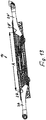
- FIGS. 7 to 14 Referenced To explain a second embodiment of a furniture drive according to the invention is hereinafter referred to the FIGS. 7 to 14 Referenced.
- a second embodiment of a double drive 14 according to the invention is shown, are mounted on the base body 16 in accordance with the first embodiment, pivot elements in the form of pivoting levers 26, 26 each about a pivot axis 28, 28 'pivotally mounted.
- the double drive 14 is designed for tool-less mounting on a support means for a box spring mattress or a cushion bed, as has been explained for the first embodiment.
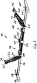
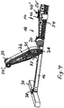
- Fig. 7 shows the dual drive 14 in an initial position of the adjustment movement with a position of the pivot lever 26, 26, which corresponds to an adjustment position of the support means in which the support members span a substantially horizontal support plane.
- Fig. 8 shows the double drive according to Fig. 7 in a position of the pivot lever 26, 26 ', which corresponds to an end position of the adjusting movement, in which the supporting parts are adjusted relative to each other maximum.
- the second embodiment differs from the first embodiment initially in that the base body 16 is formed as a housing 50, in which the pivot levers 26, 26 'associated drive units are added.
- the housing 50 consists in the illustrated embodiment of two half-shells 52, 52 'made of plastic.
- the half-shells 52, 52 ' are screw-connected or screw-connected with each other.
- fastening tabs 54, 54 ' are integrally formed on the half-shells 52, 52, as in Fig. 8 and especially good at Fig. 14 recognizable.
- the assembly of the double drive 14 on a support means takes place in principle in the same manner as explained in relation to the first embodiment.
- the double drive 14 is placed by means of the support elements 38, 38 'on the transverse struts of the support means.
- the double drive 14 can be screwed via the fastening straps 54, 54 'with its housing with a stationary central support part of a support device.
- the screw can be made in particular via a tool-operated screwing.
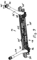
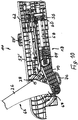
- Fig. 9 shows the double drive 14 in the adjustment accordingly Fig. 1 , wherein for reasons of explanation of the structure of the drive units 18, 18 ', the half-shell 52 of the housing 16 is omitted. Below, only the drive unit 18 is explained in detail, the drive unit 18 'is constructed accordingly and will therefore not be explained in detail.
- the drive unit 18 has a rotatably mounted in the housing 16, stationary spindle nut 56 which is mounted on a rotatably mounted in the housing 16 and movable in its axial direction threaded spindle 58.
- a worm wheel 60 is rotatably connected, which is in engagement with a screw 62 which is in engagement with the drive shaft of an electric motor of the drive unit 18, so that the threaded spindle 58 according to the direction of rotation of the drive shaft of the electric motor in Fig. 10 moved to the left or right.
- a pressure piece 64 is placed on the pivot axis 28 facing the end of the threaded spindle 58.
- the pivot lever 26 is formed as a two-armed lever in the second embodiment, the first lever arm 66, the associated to be adjusted support member loosely applied and the second lever arm 68 is in driving connection with the drive member 18 formed by the pressure member 64 drive unit.
- a tab 70 is arranged, the first End remote from the pivot axis 28 is pivotally connected to the second lever arm 68 and the second end of the pressure piece 64 can be pressurized or during the adjustment is pressurized.
- the pressure piece acts on the second end of the tab 70 by means of an engagement surface loose.
- Fig. 11 shows the drive unit 18, wherein the pressure piece 64 is omitted for explanation.
- Fig. 12 shows the pressure piece 64 taken by itself, in particular an engagement surface 72 of the pressure piece 64 can be seen.
- the engagement surface 72 and the second end of the tab are profiled in cross-section and formed complementary to each other.
- the engagement surface 64 is concave in cross-section and the second end of the tab is correspondingly complementarily convex, with the engagement surface 72 and the end of the tab 70 being arcuate in cross-section.
- spring means are provided which are formed in this embodiment between an inner wall of the housing 50 and the tab 70 acting tension spring in the form of a coil spring 74.
- end position of the adjustment movement of the electric motor drives the spindle nut 56 such that the threaded spindle 58 with the pressure piece 64 in Fig. 10 moved to the left.
- the pressure member 64 presses against the second end of the tab 70.
- the coil spring 74 is the second end of the Tab 70 is held in engagement with the engagement surface 72.
- the tab 70 is provided at its lower end with a handle member 76 which is accessible through an opening formed in the housing 50, as is apparent from Fig. 8 is apparent.
- the grip element 76 By means of the grip element 76, the tab 70 can be pulled down and moved out of the path of movement of the pressure piece 64. Subsequently, the pivot lever with the thus adjusted support member in Fig. 10 be reset counterclockwise, wherein the tab 70 moves outside of the housing 50 below the stopped pressure piece.
- the pivot lever 26 can be moved by hand Fig. 10 to be moved clockwise, the tab 70 again comes under the action of the coil spring 74 into engagement with the engagement surface 72 of the pressure piece 64.
- Fig. 13 is the distance between the pivot axes 28, 28 'to each other marked with "A".
- the distance "A" is greater than 620 mm. In this way, arise in the adjustment of support parts of a support particularly favorable conditions.
Landscapes
- Health & Medical Sciences (AREA)
- General Health & Medical Sciences (AREA)
- Nursing (AREA)
- Invalid Beds And Related Equipment (AREA)
Applications Claiming Priority (3)
| Application Number | Priority Date | Filing Date | Title |
|---|---|---|---|
| DE102016108033 | 2016-04-29 | ||
| DE102016113980 | 2016-07-28 | ||
| DE102016116250.7A DE102016116250A1 (de) | 2016-04-29 | 2016-08-31 | Elektromotorischer Doppelantrieb |
Publications (3)
| Publication Number | Publication Date |
|---|---|
| EP3238573A2 true EP3238573A2 (fr) | 2017-11-01 |
| EP3238573A3 EP3238573A3 (fr) | 2018-02-14 |
| EP3238573B1 EP3238573B1 (fr) | 2019-06-12 |
Family
ID=58579070
Family Applications (1)
| Application Number | Title | Priority Date | Filing Date |
|---|---|---|---|
| EP17167278.5A Active EP3238573B1 (fr) | 2016-04-29 | 2017-04-20 | Entraînement double à moteur électrique |
Country Status (1)
| Country | Link |
|---|---|
| EP (1) | EP3238573B1 (fr) |
Cited By (2)
| Publication number | Priority date | Publication date | Assignee | Title |
|---|---|---|---|---|
| DE202022101259U1 (de) | 2022-03-08 | 2023-06-14 | De Werth Group Ag | Boxspring-Bett |
| DE102022105381A1 (de) | 2022-03-08 | 2023-09-14 | De Werth Group Ag | Boxspring-Bett |
Family Cites Families (4)
| Publication number | Priority date | Publication date | Assignee | Title |
|---|---|---|---|---|
| US5063623A (en) * | 1990-10-15 | 1991-11-12 | Bathrick Leeland M | Power module for an ariculated bed |
| US5537701A (en) * | 1994-03-15 | 1996-07-23 | Maxwell Products, Inc. | Adjustable articulated bed |
| US6990698B2 (en) * | 2004-05-12 | 2006-01-31 | Wall Sr Daniel P | UPS shippable adjustable articulating bed |
| US8935817B2 (en) * | 2013-06-17 | 2015-01-20 | Pragma Corporation | Motorized foldable bed frame assembly |
-
2017
- 2017-04-20 EP EP17167278.5A patent/EP3238573B1/fr active Active
Non-Patent Citations (1)
| Title |
|---|
| None |
Cited By (2)
| Publication number | Priority date | Publication date | Assignee | Title |
|---|---|---|---|---|
| DE202022101259U1 (de) | 2022-03-08 | 2023-06-14 | De Werth Group Ag | Boxspring-Bett |
| DE102022105381A1 (de) | 2022-03-08 | 2023-09-14 | De Werth Group Ag | Boxspring-Bett |
Also Published As
| Publication number | Publication date |
|---|---|
| EP3238573B1 (fr) | 2019-06-12 |
| EP3238573A3 (fr) | 2018-02-14 |
Similar Documents
| Publication | Publication Date | Title |
|---|---|---|
| DE102016116253A1 (de) | Elektromotorischer Doppelantrieb | |
| EP2792277B1 (fr) | Entraînement de meuble à moteur électrique | |
| EP1410743B1 (fr) | Support réglable par moteur et destiné au rembourrage d'un meuble d'assise et/ou de couchage, par exemple d'un matelas ou d'un lit | |
| DE102004016048A1 (de) | Baukastensystem zur Montage motorisch verstellbarer Stützeinrichtungen zur Polsterung von Sitz- und/oder Liegemöbel | |
| EP2974622A1 (fr) | Dispositif d'appui reglable a moteur electrique | |
| EP1603433A1 (fr) | Systeme modulaire pour le montage de dispositifs de soutien, pouvant etre deplaces au moyen d'un moteur, destines au rembourrage de meubles d'assise et/ou couchage | |
| DE102014115033A1 (de) | Elektromotorisch verstellbare Stützeinrichtung | |
| DE102020131206A1 (de) | Elektromotorisch verstellbare Stützeinrichtung | |
| EP3491973A1 (fr) | Dispositif de support réglable par moteur électrique | |
| DE202013007106U1 (de) | Möbelantrieb | |
| EP3157389A1 (fr) | Entraînement à moteur électrique pour meuble | |
| EP3238573B1 (fr) | Entraînement double à moteur électrique | |
| DE102016116255A1 (de) | Elektromotorischer Möbelantrieb | |
| WO2005104903A1 (fr) | Systeme modulaire pour le montage de dispositifs d'appui a deplacement par moteur pour rembourrages de mobilier de type siege et/ou couchette | |
| DE102020131204A1 (de) | Elektromotorisch verstellbare Stützeinrichtung | |
| EP3238574B1 (fr) | Entraînement double à moteur électrique | |
| DE102014115084A1 (de) | Möbelantrieb | |
| DE102022111839A1 (de) | Elektromotorisch verstellbare Stützeinrichtung | |
| DE202021101529U1 (de) | Antrieb für einen Lattenrost und Bausatz zum Nachrüsten eines manuell verstellbaren Lattenrosts mit diesem Antrieb | |
| DE102016116252A1 (de) | Elektromotorischer Möbelantrieb | |
| EP4458219A1 (fr) | Entraînement double par moteur électrique | |
| DE202025102777U1 (de) | Verstellbarer Lattenrost | |
| DE202022101259U1 (de) | Boxspring-Bett | |
| DE202019103303U1 (de) | Elektromotorischer Möbelantrieb | |
| DE102021102440A1 (de) | Elektromotorische Verstellvorrichtung |
Legal Events
| Date | Code | Title | Description |
|---|---|---|---|
| PUAI | Public reference made under article 153(3) epc to a published international application that has entered the european phase |
Free format text: ORIGINAL CODE: 0009012 |
|
| STAA | Information on the status of an ep patent application or granted ep patent |
Free format text: STATUS: THE APPLICATION HAS BEEN PUBLISHED |
|
| AK | Designated contracting states |
Kind code of ref document: A2 Designated state(s): AL AT BE BG CH CY CZ DE DK EE ES FI FR GB GR HR HU IE IS IT LI LT LU LV MC MK MT NL NO PL PT RO RS SE SI SK SM TR |
|
| AX | Request for extension of the european patent |
Extension state: BA ME |
|
| PUAL | Search report despatched |
Free format text: ORIGINAL CODE: 0009013 |
|
| AK | Designated contracting states |
Kind code of ref document: A3 Designated state(s): AL AT BE BG CH CY CZ DE DK EE ES FI FR GB GR HR HU IE IS IT LI LT LU LV MC MK MT NL NO PL PT RO RS SE SI SK SM TR |
|
| AX | Request for extension of the european patent |
Extension state: BA ME |
|
| RIC1 | Information provided on ipc code assigned before grant |
Ipc: A47C 20/04 20060101AFI20180109BHEP |
|
| STAA | Information on the status of an ep patent application or granted ep patent |
Free format text: STATUS: REQUEST FOR EXAMINATION WAS MADE |
|
| 17P | Request for examination filed |
Effective date: 20180814 |
|
| RBV | Designated contracting states (corrected) |
Designated state(s): AL AT BE BG CH CY CZ DE DK EE ES FI FR GB GR HR HU IE IS IT LI LT LU LV MC MK MT NL NO PL PT RO RS SE SI SK SM TR |
|
| GRAP | Despatch of communication of intention to grant a patent |
Free format text: ORIGINAL CODE: EPIDOSNIGR1 |
|
| STAA | Information on the status of an ep patent application or granted ep patent |
Free format text: STATUS: GRANT OF PATENT IS INTENDED |
|
| INTG | Intention to grant announced |
Effective date: 20181212 |
|
| GRAS | Grant fee paid |
Free format text: ORIGINAL CODE: EPIDOSNIGR3 |
|
| GRAA | (expected) grant |
Free format text: ORIGINAL CODE: 0009210 |
|
| STAA | Information on the status of an ep patent application or granted ep patent |
Free format text: STATUS: THE PATENT HAS BEEN GRANTED |
|
| AK | Designated contracting states |
Kind code of ref document: B1 Designated state(s): AL AT BE BG CH CY CZ DE DK EE ES FI FR GB GR HR HU IE IS IT LI LT LU LV MC MK MT NL NO PL PT RO RS SE SI SK SM TR |
|
| REG | Reference to a national code |
Ref country code: GB Ref legal event code: FG4D Free format text: NOT ENGLISH |
|
| REG | Reference to a national code |
Ref country code: CH Ref legal event code: EP |
|
| REG | Reference to a national code |
Ref country code: AT Ref legal event code: REF Ref document number: 1141440 Country of ref document: AT Kind code of ref document: T Effective date: 20190615 |
|
| REG | Reference to a national code |
Ref country code: DE Ref legal event code: R096 Ref document number: 502017001516 Country of ref document: DE |
|
| REG | Reference to a national code |
Ref country code: IE Ref legal event code: FG4D Free format text: LANGUAGE OF EP DOCUMENT: GERMAN |
|
| REG | Reference to a national code |
Ref country code: NL Ref legal event code: MP Effective date: 20190612 |
|
| REG | Reference to a national code |
Ref country code: LT Ref legal event code: MG4D |
|
| PG25 | Lapsed in a contracting state [announced via postgrant information from national office to epo] |
Ref country code: NO Free format text: LAPSE BECAUSE OF FAILURE TO SUBMIT A TRANSLATION OF THE DESCRIPTION OR TO PAY THE FEE WITHIN THE PRESCRIBED TIME-LIMIT Effective date: 20190912 Ref country code: FI Free format text: LAPSE BECAUSE OF FAILURE TO SUBMIT A TRANSLATION OF THE DESCRIPTION OR TO PAY THE FEE WITHIN THE PRESCRIBED TIME-LIMIT Effective date: 20190612 Ref country code: LT Free format text: LAPSE BECAUSE OF FAILURE TO SUBMIT A TRANSLATION OF THE DESCRIPTION OR TO PAY THE FEE WITHIN THE PRESCRIBED TIME-LIMIT Effective date: 20190612 Ref country code: AL Free format text: LAPSE BECAUSE OF FAILURE TO SUBMIT A TRANSLATION OF THE DESCRIPTION OR TO PAY THE FEE WITHIN THE PRESCRIBED TIME-LIMIT Effective date: 20190612 Ref country code: HR Free format text: LAPSE BECAUSE OF FAILURE TO SUBMIT A TRANSLATION OF THE DESCRIPTION OR TO PAY THE FEE WITHIN THE PRESCRIBED TIME-LIMIT Effective date: 20190612 Ref country code: SE Free format text: LAPSE BECAUSE OF FAILURE TO SUBMIT A TRANSLATION OF THE DESCRIPTION OR TO PAY THE FEE WITHIN THE PRESCRIBED TIME-LIMIT Effective date: 20190612 |
|
| PG25 | Lapsed in a contracting state [announced via postgrant information from national office to epo] |
Ref country code: GR Free format text: LAPSE BECAUSE OF FAILURE TO SUBMIT A TRANSLATION OF THE DESCRIPTION OR TO PAY THE FEE WITHIN THE PRESCRIBED TIME-LIMIT Effective date: 20190913 Ref country code: LV Free format text: LAPSE BECAUSE OF FAILURE TO SUBMIT A TRANSLATION OF THE DESCRIPTION OR TO PAY THE FEE WITHIN THE PRESCRIBED TIME-LIMIT Effective date: 20190612 Ref country code: RS Free format text: LAPSE BECAUSE OF FAILURE TO SUBMIT A TRANSLATION OF THE DESCRIPTION OR TO PAY THE FEE WITHIN THE PRESCRIBED TIME-LIMIT Effective date: 20190612 Ref country code: BG Free format text: LAPSE BECAUSE OF FAILURE TO SUBMIT A TRANSLATION OF THE DESCRIPTION OR TO PAY THE FEE WITHIN THE PRESCRIBED TIME-LIMIT Effective date: 20190912 |
|
| PG25 | Lapsed in a contracting state [announced via postgrant information from national office to epo] |
Ref country code: RO Free format text: LAPSE BECAUSE OF FAILURE TO SUBMIT A TRANSLATION OF THE DESCRIPTION OR TO PAY THE FEE WITHIN THE PRESCRIBED TIME-LIMIT Effective date: 20190612 Ref country code: SK Free format text: LAPSE BECAUSE OF FAILURE TO SUBMIT A TRANSLATION OF THE DESCRIPTION OR TO PAY THE FEE WITHIN THE PRESCRIBED TIME-LIMIT Effective date: 20190612 Ref country code: NL Free format text: LAPSE BECAUSE OF FAILURE TO SUBMIT A TRANSLATION OF THE DESCRIPTION OR TO PAY THE FEE WITHIN THE PRESCRIBED TIME-LIMIT Effective date: 20190612 Ref country code: CZ Free format text: LAPSE BECAUSE OF FAILURE TO SUBMIT A TRANSLATION OF THE DESCRIPTION OR TO PAY THE FEE WITHIN THE PRESCRIBED TIME-LIMIT Effective date: 20190612 Ref country code: PT Free format text: LAPSE BECAUSE OF FAILURE TO SUBMIT A TRANSLATION OF THE DESCRIPTION OR TO PAY THE FEE WITHIN THE PRESCRIBED TIME-LIMIT Effective date: 20191014 Ref country code: EE Free format text: LAPSE BECAUSE OF FAILURE TO SUBMIT A TRANSLATION OF THE DESCRIPTION OR TO PAY THE FEE WITHIN THE PRESCRIBED TIME-LIMIT Effective date: 20190612 |
|
| PG25 | Lapsed in a contracting state [announced via postgrant information from national office to epo] |
Ref country code: IT Free format text: LAPSE BECAUSE OF FAILURE TO SUBMIT A TRANSLATION OF THE DESCRIPTION OR TO PAY THE FEE WITHIN THE PRESCRIBED TIME-LIMIT Effective date: 20190612 Ref country code: IS Free format text: LAPSE BECAUSE OF FAILURE TO SUBMIT A TRANSLATION OF THE DESCRIPTION OR TO PAY THE FEE WITHIN THE PRESCRIBED TIME-LIMIT Effective date: 20191012 Ref country code: SM Free format text: LAPSE BECAUSE OF FAILURE TO SUBMIT A TRANSLATION OF THE DESCRIPTION OR TO PAY THE FEE WITHIN THE PRESCRIBED TIME-LIMIT Effective date: 20190612 |
|
| REG | Reference to a national code |
Ref country code: DE Ref legal event code: R097 Ref document number: 502017001516 Country of ref document: DE |
|
| PG25 | Lapsed in a contracting state [announced via postgrant information from national office to epo] |
Ref country code: TR Free format text: LAPSE BECAUSE OF FAILURE TO SUBMIT A TRANSLATION OF THE DESCRIPTION OR TO PAY THE FEE WITHIN THE PRESCRIBED TIME-LIMIT Effective date: 20190612 |
|
| PLBE | No opposition filed within time limit |
Free format text: ORIGINAL CODE: 0009261 |
|
| STAA | Information on the status of an ep patent application or granted ep patent |
Free format text: STATUS: NO OPPOSITION FILED WITHIN TIME LIMIT |
|
| PG25 | Lapsed in a contracting state [announced via postgrant information from national office to epo] |
Ref country code: DK Free format text: LAPSE BECAUSE OF FAILURE TO SUBMIT A TRANSLATION OF THE DESCRIPTION OR TO PAY THE FEE WITHIN THE PRESCRIBED TIME-LIMIT Effective date: 20190612 Ref country code: PL Free format text: LAPSE BECAUSE OF FAILURE TO SUBMIT A TRANSLATION OF THE DESCRIPTION OR TO PAY THE FEE WITHIN THE PRESCRIBED TIME-LIMIT Effective date: 20190612 |
|
| 26N | No opposition filed |
Effective date: 20200313 |
|
| PG25 | Lapsed in a contracting state [announced via postgrant information from national office to epo] |
Ref country code: SI Free format text: LAPSE BECAUSE OF FAILURE TO SUBMIT A TRANSLATION OF THE DESCRIPTION OR TO PAY THE FEE WITHIN THE PRESCRIBED TIME-LIMIT Effective date: 20190612 Ref country code: IS Free format text: LAPSE BECAUSE OF FAILURE TO SUBMIT A TRANSLATION OF THE DESCRIPTION OR TO PAY THE FEE WITHIN THE PRESCRIBED TIME-LIMIT Effective date: 20200224 |
|
| PG2D | Information on lapse in contracting state deleted |
Ref country code: IS |
|
| PG25 | Lapsed in a contracting state [announced via postgrant information from national office to epo] |
Ref country code: ES Free format text: LAPSE BECAUSE OF FAILURE TO SUBMIT A TRANSLATION OF THE DESCRIPTION OR TO PAY THE FEE WITHIN THE PRESCRIBED TIME-LIMIT Effective date: 20190612 |
|
| PG25 | Lapsed in a contracting state [announced via postgrant information from national office to epo] |
Ref country code: MC Free format text: LAPSE BECAUSE OF FAILURE TO SUBMIT A TRANSLATION OF THE DESCRIPTION OR TO PAY THE FEE WITHIN THE PRESCRIBED TIME-LIMIT Effective date: 20190612 |
|
| REG | Reference to a national code |
Ref country code: CH Ref legal event code: PL |
|
| PG25 | Lapsed in a contracting state [announced via postgrant information from national office to epo] |
Ref country code: LI Free format text: LAPSE BECAUSE OF NON-PAYMENT OF DUE FEES Effective date: 20200430 Ref country code: LU Free format text: LAPSE BECAUSE OF NON-PAYMENT OF DUE FEES Effective date: 20200420 Ref country code: CH Free format text: LAPSE BECAUSE OF NON-PAYMENT OF DUE FEES Effective date: 20200430 Ref country code: FR Free format text: LAPSE BECAUSE OF NON-PAYMENT OF DUE FEES Effective date: 20200430 |
|
| REG | Reference to a national code |
Ref country code: BE Ref legal event code: MM Effective date: 20200430 |
|
| PG25 | Lapsed in a contracting state [announced via postgrant information from national office to epo] |
Ref country code: BE Free format text: LAPSE BECAUSE OF NON-PAYMENT OF DUE FEES Effective date: 20200430 |
|
| PG25 | Lapsed in a contracting state [announced via postgrant information from national office to epo] |
Ref country code: IE Free format text: LAPSE BECAUSE OF NON-PAYMENT OF DUE FEES Effective date: 20200420 |
|
| GBPC | Gb: european patent ceased through non-payment of renewal fee |
Effective date: 20210420 |
|
| PG25 | Lapsed in a contracting state [announced via postgrant information from national office to epo] |
Ref country code: GB Free format text: LAPSE BECAUSE OF NON-PAYMENT OF DUE FEES Effective date: 20210420 |
|
| PG25 | Lapsed in a contracting state [announced via postgrant information from national office to epo] |
Ref country code: MT Free format text: LAPSE BECAUSE OF FAILURE TO SUBMIT A TRANSLATION OF THE DESCRIPTION OR TO PAY THE FEE WITHIN THE PRESCRIBED TIME-LIMIT Effective date: 20190612 Ref country code: CY Free format text: LAPSE BECAUSE OF FAILURE TO SUBMIT A TRANSLATION OF THE DESCRIPTION OR TO PAY THE FEE WITHIN THE PRESCRIBED TIME-LIMIT Effective date: 20190612 |
|
| PG25 | Lapsed in a contracting state [announced via postgrant information from national office to epo] |
Ref country code: MK Free format text: LAPSE BECAUSE OF FAILURE TO SUBMIT A TRANSLATION OF THE DESCRIPTION OR TO PAY THE FEE WITHIN THE PRESCRIBED TIME-LIMIT Effective date: 20190612 |
|
| PGFP | Annual fee paid to national office [announced via postgrant information from national office to epo] |
Ref country code: DE Payment date: 20220430 Year of fee payment: 6 |
|
| REG | Reference to a national code |
Ref country code: DE Ref legal event code: R082 Ref document number: 502017001516 Country of ref document: DE Representative=s name: HOEFER & PARTNER PATENTANWAELTE MBB, DE |
|
| REG | Reference to a national code |
Ref country code: AT Ref legal event code: MM01 Ref document number: 1141440 Country of ref document: AT Kind code of ref document: T Effective date: 20220420 |
|
| PG25 | Lapsed in a contracting state [announced via postgrant information from national office to epo] |
Ref country code: AT Free format text: LAPSE BECAUSE OF NON-PAYMENT OF DUE FEES Effective date: 20220420 |
|
| REG | Reference to a national code |
Ref country code: DE Ref legal event code: R119 Ref document number: 502017001516 Country of ref document: DE |
|
| PG25 | Lapsed in a contracting state [announced via postgrant information from national office to epo] |
Ref country code: DE Free format text: LAPSE BECAUSE OF NON-PAYMENT OF DUE FEES Effective date: 20231103 |