EP3238976A1 - Dispositif et procédé destinés au réglage de traction constante d'un frotteur - Google Patents
Dispositif et procédé destinés au réglage de traction constante d'un frotteur Download PDFInfo
- Publication number
- EP3238976A1 EP3238976A1 EP17167451.8A EP17167451A EP3238976A1 EP 3238976 A1 EP3238976 A1 EP 3238976A1 EP 17167451 A EP17167451 A EP 17167451A EP 3238976 A1 EP3238976 A1 EP 3238976A1
- Authority
- EP
- European Patent Office
- Prior art keywords
- speed
- measuring device
- travel
- wind
- wind speed
- Prior art date
- Legal status (The legal status is an assumption and is not a legal conclusion. Google has not performed a legal analysis and makes no representation as to the accuracy of the status listed.)
- Granted
Links
Images

Classifications
-
- B—PERFORMING OPERATIONS; TRANSPORTING
- B60—VEHICLES IN GENERAL
- B60L—PROPULSION OF ELECTRICALLY-PROPELLED VEHICLES; SUPPLYING ELECTRIC POWER FOR AUXILIARY EQUIPMENT OF ELECTRICALLY-PROPELLED VEHICLES; ELECTRODYNAMIC BRAKE SYSTEMS FOR VEHICLES IN GENERAL; MAGNETIC SUSPENSION OR LEVITATION FOR VEHICLES; MONITORING OPERATING VARIABLES OF ELECTRICALLY-PROPELLED VEHICLES; ELECTRIC SAFETY DEVICES FOR ELECTRICALLY-PROPELLED VEHICLES
- B60L5/00—Current collectors for power supply lines of electrically-propelled vehicles
- B60L5/18—Current collectors for power supply lines of electrically-propelled vehicles using bow-type collectors in contact with trolley wire
- B60L5/22—Supporting means for the contact bow
- B60L5/28—Devices for lifting and resetting the collector
- B60L5/32—Devices for lifting and resetting the collector using fluid pressure
Definitions
- the invention relates to a control system and a method for controlling a pressing force of a contact piece of a pantograph of a rail vehicle, wherein the arranged thereon by means of a positioning of the pantograph grinding piece is applied with the pressing force against a catenary system, wherein by means of a travel measuring device of a measuring device of a control system of the rail vehicle a travel speed of the rail vehicle is determined, wherein by means of a control device of the control system, the pressing force is regulated in dependence on the driving speed.
- Such control systems and methods are well known and are used in rail vehicles with pantographs, in particular trains or the like.
- Current collectors are regularly arranged on a roof of a rail vehicle and comprise a movable positioning device, which can be designed as a rocker, a pantograph or a Einarmsystem.
- a movable positioning device which can be designed as a rocker, a pantograph or a Einarmsystem.
- At an upper end of the positioning device are one or more sliding pieces arranged, wherein the grinding pieces are formed substantially of graphite.
- the positioning device is moved by means of a pneumatic or electric drive, pneumatic drives predominantly being used in particular for trains.
- Above the pneumatic drive which can have one or more actuators, the contact piece is pressed against a contact line or a contact wire above the rail vehicle with a contact pressure force.
- a pressing force must be so great that the sliding piece is not disconnected from the catenary during travel of the rail vehicle or takes off, as this can lead to an undesirable sparkover between the catenary and contact piece, which in turn promotes rapid wear of the contact strip or a break can result. Therefore, the pressure force of the contact strip on the catenary is always controlled in response to a travel speed of the rail vehicle. Under the pressure force is here an orthogonal to the longitudinal extent of the catenary acting force that is exerted by the contact strip on the catenary understood.
- Rail vehicles also have a travel measuring device for measuring a travel speed of the rail vehicle. This travel speed is used to control the pressure force by means of a control device of a control system of the rail vehicle. If the rail vehicle has a pneumatic drive of the positioning device, by means of a so-called proportional pressure regulator, a pressure of an actuator on the positioning device, and thus a pressing force of the sliding piece on the catenary depending on the travel speed can be controlled so that the contact pressure is increased with increasing travel speed. Thus, it can be prevented that the contact strip dissolves undesirably even at high speeds of the catenary. At high speeds, speeds are understood> 100 km / h.
- a disadvantage of the known method is that with increasing travel speed of the rail vehicle, a wind at a travel speed corresponding to the wind speed acts on the pantograph or the sliding piece and presses the contact strip due to aerodynamic effects on the catenary. That is, as the vehicle speed increases, a pressing force is increased by a vehicle speed force component.
- the higher the pressure force of the contact strip on the catenary is formed the higher is also the abrasion of the formed of graphite contact piece and thus a wear of the same.
- a wear of the grinding piece is again significantly increased when a rail vehicle or train at high speed passes through a tunnel. Newer tunnels can be designed with a length of many kilometers and with a single tunnel tube for a track alone.
- the object of the invention is therefore to propose a method for controlling a pressing force of a contact strip and a control system for a pantograph, which prolongs a service life of a contact strip.
- a pressing force (F A ) of a contact strip of a current collector of a rail vehicle a sliding device of a measuring device of a control system of the rail vehicle, a travel speed (vF) of the rail vehicle is determined by means of a positioning device of the pantograph with the contact pressure (F A ) against a contact line, said means of a control device of the control system the pressure force (F A ) is controlled as a function of the travel speed (vF), wherein a real wind speed (vW R ) relative to the rail vehicle is determined by means of a wind measuring device of the measuring device, wherein by means of the control device, the pressing force (F A ) taking into account the real wind speed (vW R ) is regulated.
- the wind measuring device is used to measure the real wind speed (vW R ).
- the real wind speed (vW R ) results from the wind conditions which prevail at the location of the rail vehicle or directly at the pantograph independently of a traveling wind speed (vW F ). Since the pressure force (F A ) is already regulated by the control device as a function of the travel speed (vF), it becomes possible to correct the pressure force (F A ) by supplementing the measurement of the real wind speed (vW R ). For example, if a rail vehicle passes through a tunnel, the pressure force (F A ) would increase substantially in an undesired manner due to the aerodynamic effects.
- the pressing force (F A ) can always be controlled in proportion to the travel speed (vF).
- the control system may therefore include, for example, a known proportional pressure regulator, which regulates a pressure for a pneumatic actuator.
- the method for controlling a pressing force (F A ) can also be carried out by retrofitting proportional pressure regulators with the control device.
- the travel speed (vF) may correspond to a travel wind speed (vW F ), wherein the real wind speed (vW R ) may be determined as the difference between a total wind speed (vW ges ) and the travel speed (vF) or the airstream speed (vW F ).
- a measurement of the travel speed (vF) is carried out regularly on each rail vehicle, for example on a wheel of a rail vehicle, so that the control device can easily process this then known size.
- the travel wind speed (vW F ) can be measured once again separately by means of the wind measuring device.
- a real wind speed (vW R ) can then be determined particularly easily, for example by means of a Prandtl tube.
- a total speed (vW ges ) can be measured on the positioning device.
- a simple pitot tube can be used as the wind measuring device when the vehicle speed (vF) or the vehicle speed (vW F ) is already known.
- the wind measuring device is then particularly easy to train.
- the wind measuring device can also be arranged directly on the positioning device, in particular adjacent to the grinding piece, in order to determine the actual wind conditions or flow conditions on the grinding piece.
- the pressure force (F A ) is then more precisely regulated.
- a driving wind speed force component (F WFY ) may be determined depending on the running speed (vF) or a running wind speed (vW F ) and / or a real wind speed force component (F WRY ) depending on the real wind speed (vW R ) by means of the control device.
- the travel wind speed (vW F ) and the real wind speed (vW R ) act on the contact block in the opposite direction to the direction of movement of the contact piece relative to the contact line.
- the real wind speed (vW R ) can also be a component of a wind acting laterally on the rail vehicle.
- the pressing force (F A ) may be the sum of the negative real wind speed force component (F WRY ) and the travel speed force component (F AvK ), and the travel speed force component (F AvK ) may be controlled by the control device. Consequently, in the regulation of the pressing force (F A ) alone, the force component (F AvK ) provided for the respective speed of the rail vehicle and the real wind speed force component can be used (F WRY ). Theêtwind Anthony-force component (F WFY ) can then be neglected. Alone by this consideration of the real wind speed (vW R ), it is already possible to significantly reduce wear of the contact strip and to improve contact quality.
- a service life of the grinding piece can be further increased if the pressing force (F A ) is the sum of the traveling-wind speed force component (F WFY ), the real-speed negative force component (F WRY ) and the vehicle speed force component (F AvK ) the travel speed force component (F AvK ) can be controlled by the control device.
- the pressure force (F A ) can be adapted to all the pressure force influencing aerodynamic forces.
- the traveling wind speed force component (F WFY ) and the traveling speed force component (F AvK ) may be determined by considering the height of the grinding piece by means of the control device.
- a height of the grinding piece is in principle dependent on its wear, so that a new contact piece regularly is always higher than a long time in use befindliches contact strip, since here the height has already been reduced by abrasion.
- the height of the grinding piece also has an effect on the aerodynamic behavior of the grinding piece and thus, in particular, on the pressure force (F A ) influenced by wind speeds.
- the control device may now determine or compute the vehicle wind speed force component (F WFY ) and the vehicle speed force component (F AvK ) based on a known height of the slider . It can be provided to measure the height of the contact strip at regular intervals by means of a height measuring device in order to regulate the pressure force (F A ) even more precisely.
- a function of values of the real wind speed (vW R ) and values of the Real wind velocity force component (F WRY ) are stored.
- the control device may accordingly comprise means for data processing with the storage device.
- the function stored in the memory device then allows an association of the real wind speed (vW R ) determined by the wind measuring device to a value of the real wind speed force component (F WRY ).
- the regulation of the pressure force (F A ) is further simplified.
- a calibration of the function by a measurement of the pressing force (F A ) and a total wind speed (vW ges ) take place.
- the contact pressure (F A ) of the contact strip on the contact line can be determined, for example, by means of force sensors which are arranged on or in the vicinity of the contact strip.
- the actual pressure force as a function of the total wind speed (vW ges ) can be determined, in which case each of the function can be adjusted so that the control device always the desired pressure force (F A ), which is adapted to the travel speed (vF) adjusted.
- the calibration makes it possible to apply the method to any types and models of rail vehicles or pantographs, since then the respective different flow conditions can be taken into account on the rail vehicles.
- a height of the grinding piece can be measured continuously, wherein by means of the regulating device, the pressing force is controlled taking into account the height.
- the height measuring device can be, for example, a camera that detects the contact strip or a sensor that is installed on or within the contact strip. It is essential that the height of the contact strip during operation can be continuously measured, so that the pressure force (F A ) can always be adapted to the same by means of the control device to a constantly changing height by abrasion of the contact strip. In addition to the regulation of the pressure force (F A ) can then be initiated by means of the height measuring device also a lowering of the sliding piece when the grinding piece falls below a minimum height to prevent damage to the catenary.
- the pantograph on a movable positioning and at least one arranged thereon sliding piece, wherein by means of the positioning device, the sliding piece with a pressing force (F A ) against a catenary to the plant can be brought
- the control system is a measuring device and a control device, wherein the measuring device has a travel measuring device for determining a travel speed (vF) of a rail vehicle, wherein by means of the control device, the pressing force (F A ) is controllable in dependence on the vehicle speed (vF), wherein the measuring device is a wind measuring device for determining a real Wind speed (vW R ) relative to the rail vehicle, wherein by means of the control device, the pressing force (F A ), taking into account the real wind speed (vW R ) is adjustable.
- the wind measuring device may be a Venturi tube, a pitot tube, a Prandtl tube or an anemometer, in particular an ultrasonic anemometer, a thermoelectric anemometer, a thermo-optical anemometer, a plate anemometer.
- the wind measuring device for measuring the real wind velocity (VW R) or a total wind speed (VW ges) formed.
- the wind measuring device may be arranged on a roof of the rail vehicle in the vicinity of the current collector or directly on the positioning device adjacent to the contact strip.
- the wind gauge may include a fiber optic air velocity sensor.
- the fiber optic sensor can then form a thermo-optical anemometer. It is particularly advantageous that the fiber optic sensor can not be influenced by electromagnetic fields as they are present at pantographs regularly.
- the fiber-optic sensor can therefore also be arranged adjacent to the contact strip, without the result of the measurement being able to be distorted by currents flowing through the contact block or, for example, a flashover. Also, the sensor can not be disabled as a pitot tube due to contamination.
- the measuring device may comprise a height measuring device, by means of which a height of the grinding piece is measurable, wherein the height measuring device may comprise a fiber-optic sensor which may be disposed within the grinding piece.
- the fiber optic sensor for measuring the height of the contact strip is then also not influenced by electromagnetic fields.
- the height measuring device it is possible with the height measuring device to adjust the pressing force (F A ) to the actual height of the contact strip. If the fiber-optic sensor is arranged inside the contact strip, the fiber-optic sensor is also shielded from external influences that can falsify a measurement result.
- a unidirectional fiber bundle can be arranged in a vertical bore in the contact strip, wherein the fiber bundle can completely fill the bore.
- the fiber optic sensor is then formed by the fiber bundle in the bore.
- the bore may be a blind bore or a through bore in the slip piece.
- abrasion of the contact piece by contact with the contact line abrasion of the bundle of fibers also takes place, as a result of which a length of the bundle of fibers is shortened. This change in length of the fiber bundle can be detected, resulting in a height of the contact strip.
- a plurality of spaced-apart fiber bundles may be arranged in the grinding piece. The fact that the fiber bundle is only inserted into the vertical bore is the fiber optic sensor easy to assemble. It can also be provided as needed to fix or shed the fiber bundle in the bore by an adhesive material.
- the travel measuring device can be formed independently of the wind measuring device.
- the travel measuring device can then be the travel measuring device, which is in any case formed on a rail vehicle, for determining and displaying a driving speed, for example for a vehicle driver. It can then be dispensed with a supplementary training of a travel measuring device. Nevertheless, a wind speed (vW F ) can be measured by means of the wind measuring device in order to obtain an even more accurate measurement result.
- the wind measuring device may form the travel measuring device. Then, a travel speed (vF) is measured by the wind measuring device alone.
- the control system can then be designed independently of any existing already existing travel measuring device of a rail vehicle, whereby the control system is more universally applicable to rail vehicles.
- a wind measuring device When using a wind measuring device according to the invention, it is intended to use these for determining a real wind speed (vW R ) at a current collector of a rail vehicle. This makes it possible to use only the real wind speed (vW R ) for accurately controlling a pressing force (F A ) of a sliding piece of the current collector of the rail vehicle with the advantages described above.
- the Fig. 1 shows a pantograph 10 on a roof 11 of a rail vehicle not shown here with a trained as a pantograph 12 positioning device 13.
- a pantograph 12 positioning device 13 On the pantograph 12, two contact strips 14 are arranged on a rocker 15 transverse to a contact line 16.
- the rail vehicle moves at a travel speed vF relative to the catenary 16, the rail vehicle being flowed parallel to the catenary 16 at a total wind speed vW ges .
- the sliding pieces 14 are pressed transversely or orthogonally to the contact line 16 with a pressing force F A.
- the pressing force F A is controlled by means of a control device, not shown.
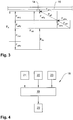
- the Fig. 2 shows a schematic representation of the contact strip 14 on the contact line 16 with vectors drawn on a vertical axis 17 of the contact strip 14 vectors.
- a total wind speed vW ges is composed of a travel wind speed vW F and a real wind speed vW R.
- the travel wind speed vW F is the same as a travel speed vF or counteracts this.
- the real wind speed vW R therefore corresponds to the proportion of a wind acting on the current collector or sliding piece 14, irrespective of the travel speed vF.
- This Wind can also be negative, ie act with the direction of travel of the rail vehicle and thus reduce the travel wind speed vW F and the total wind speed vW ges .
- the Fig. 3 shows the sliding piece 14 and the catenary 16 with a sliding piece 14 during a driving operation of the rail vehicle and then with acting force vectors.
- From the travel speed vF results in a substitutionwind mecanic force vW F , which acts transversely on the contact strip 14 due to the aerodynamic effects on the positioning device or the sliding piece 14.
- the airstream speed force vW F is subdivided into airstream speed force components F WFY and F WFX .
- the real wind speed vW R also causes a real wind speed force vW R with real wind speed force components vW RY and vW RX .
- the demandingwindiere-force component vW FY and the real wind speed force component vW RY act orthogonal to the contact line 16 on the contact strip 14 and press it together with a speed-dependent pressure force F AV against the catenary 16.
- the speed-dependent pressure force F AV is thereby from a positioning device with a Proportional pressure controller in response to a current speed vF generated and increased with increasing speed vF in a proportional ratio. This results in the increased pressure force F AE , which is higher than actually required due to the real wind speed force component F WRY , which in turn leads to increased wear and thus a shortened service life of the contact strip 14.
- the control device not shown here therefore determines the real wind speed vW R and the resulting real wind speed force component vW RY , wherein by means of the control device, the real wind speed force component vW RY is subtracted in principle from the increased pressure force F AE . However, this can also already be done when determining the wind speed. It is essential that the pressure force F A to the influence of the real wind speed force component F WRY is corrected. The pressure force F A is consequently so high that at least one pressure force required for the respective travel speed v F is applied or this is not exceeded.
- the Fig. 4 shows the basic structure of a control system 18 with a control device 19 and a drive 20 of a positioning device not shown here.
- a wind measuring device 21, a travel measuring device 22 and a height measuring device 23 supply the control device 19 with operating parameters, wherein the control device 19 exerts via the drive 20 on a not shown here grinding piece formed in dependence on the operating pressure force.
- the Fig. 5 shows a schematic representation of a fiber optic sensor 24 for air velocity measurement.
- the fiber-optic sensor 24 comprises a U-shaped profile cover 25 and a unidirectional fiber bundle 26 with a sensor end 27.
- a temperature change at the sensor end 27 can optically change a coating of the sensor end 27, not shown here, so that this change in the coating in turn via the fiber bundle 26 can be detected with an evaluation device not shown here.
- the profile cover 25 serves to protect the sensor end 27 against adverse environmental influences.
Landscapes
- Engineering & Computer Science (AREA)
- Physics & Mathematics (AREA)
- Fluid Mechanics (AREA)
- Power Engineering (AREA)
- Transportation (AREA)
- Mechanical Engineering (AREA)
- Current-Collector Devices For Electrically Propelled Vehicles (AREA)
Priority Applications (1)
| Application Number | Priority Date | Filing Date | Title |
|---|---|---|---|
| PL17167451T PL3238976T3 (pl) | 2016-04-28 | 2017-04-21 | Układ regulacji i sposób regulowania siły docisku ślizgacza łyżwowego |
Applications Claiming Priority (1)
| Application Number | Priority Date | Filing Date | Title |
|---|---|---|---|
| DE102016207311.7A DE102016207311B4 (de) | 2016-04-28 | 2016-04-28 | Regelsystem und Verfahren zur Regelung einer Andruckkraft eines Schleifstücks |
Publications (2)
| Publication Number | Publication Date |
|---|---|
| EP3238976A1 true EP3238976A1 (fr) | 2017-11-01 |
| EP3238976B1 EP3238976B1 (fr) | 2021-06-02 |
Family
ID=58709755
Family Applications (1)
| Application Number | Title | Priority Date | Filing Date |
|---|---|---|---|
| EP17167451.8A Active EP3238976B1 (fr) | 2016-04-28 | 2017-04-21 | Système et procédé destinés de contrôle de la pression de contact d'un frotteur |
Country Status (7)
| Country | Link |
|---|---|
| EP (1) | EP3238976B1 (fr) |
| DE (1) | DE102016207311B4 (fr) |
| DK (1) | DK3238976T3 (fr) |
| ES (1) | ES2879656T3 (fr) |
| HU (1) | HUE056539T2 (fr) |
| PL (1) | PL3238976T3 (fr) |
| PT (1) | PT3238976T (fr) |
Cited By (3)
| Publication number | Priority date | Publication date | Assignee | Title |
|---|---|---|---|---|
| RU2748044C1 (ru) * | 2020-07-17 | 2021-05-19 | Федеральное государственное бюджетное образовательное учреждение высшего образования "Омский государственный университет путей сообщения" | Устройство токосъема транспортного средства |
| RU2783654C1 (ru) * | 2022-04-13 | 2022-11-15 | Федеральное государственное бюджетное образовательное учреждение высшего образования "Омский государственный университет путей сообщения" | Устройство токосъёма транспортного средства |
| US20230050922A1 (en) * | 2020-01-15 | 2023-02-16 | Siemens Mobility GmbH | Road-guided motor vehicle and method for raising the pantograph of a power collector of a road-guided motor vehicle |
Families Citing this family (2)
| Publication number | Priority date | Publication date | Assignee | Title |
|---|---|---|---|---|
| SE541871C2 (en) | 2017-12-12 | 2020-01-02 | Railway Metrics And Dynamics Sweden Ab | Detection of maintenance status for a pantograph |
| DE102021127387A1 (de) | 2021-10-21 | 2023-04-27 | Kiepe Electric Gmbh | Verfahren zur automatischen Überführung einer verschwenkbaren Stromabnehmerstange |
Citations (3)
| Publication number | Priority date | Publication date | Assignee | Title |
|---|---|---|---|---|
| DE19643284A1 (de) * | 1996-10-21 | 1998-04-23 | Daimler Benz Ag | Vorrichtung zur Verminderung der Kontaktkraftschwankungen zwischen einem Stromabnehmer und einer Fahrleitung |
| EP2644433A2 (fr) * | 2012-03-30 | 2013-10-02 | Siemens Aktiengesellschaft | Véhicule doté dýune prise de courant |
| DE102013201494A1 (de) * | 2012-09-18 | 2014-03-20 | Siemens Aktiengesellschaft | Diagnoseverfahren für Schienenfahrzeuge |
Family Cites Families (3)
| Publication number | Priority date | Publication date | Assignee | Title |
|---|---|---|---|---|
| DE1084960B (de) * | 1959-04-14 | 1960-07-07 | Atlas Werke Ag | Einrichtung zur Messung absoluter Geschwindigkeiten |
| AT398735B (de) * | 1991-07-26 | 1995-01-25 | Siemens Ag Oesterreich | Überwachungseinrichtung für stromabnehmerschleifleisten |
| DE102014111264A1 (de) * | 2014-08-07 | 2016-02-11 | Kummler + Matter Ag | Stromabnehmervorrichtung und Verwendung einer solchen |
-
2016
- 2016-04-28 DE DE102016207311.7A patent/DE102016207311B4/de not_active Expired - Fee Related
-
2017
- 2017-04-21 DK DK17167451.8T patent/DK3238976T3/da active
- 2017-04-21 EP EP17167451.8A patent/EP3238976B1/fr active Active
- 2017-04-21 ES ES17167451T patent/ES2879656T3/es active Active
- 2017-04-21 PL PL17167451T patent/PL3238976T3/pl unknown
- 2017-04-21 HU HUE17167451A patent/HUE056539T2/hu unknown
- 2017-04-21 PT PT171674518T patent/PT3238976T/pt unknown
Patent Citations (3)
| Publication number | Priority date | Publication date | Assignee | Title |
|---|---|---|---|---|
| DE19643284A1 (de) * | 1996-10-21 | 1998-04-23 | Daimler Benz Ag | Vorrichtung zur Verminderung der Kontaktkraftschwankungen zwischen einem Stromabnehmer und einer Fahrleitung |
| EP2644433A2 (fr) * | 2012-03-30 | 2013-10-02 | Siemens Aktiengesellschaft | Véhicule doté dýune prise de courant |
| DE102013201494A1 (de) * | 2012-09-18 | 2014-03-20 | Siemens Aktiengesellschaft | Diagnoseverfahren für Schienenfahrzeuge |
Non-Patent Citations (1)
| Title |
|---|
| FSG FERNSTEURGERATE: "Mess-und Sensortechnik Windsensor", 30 November 2011 (2011-11-30), XP055406414, Retrieved from the Internet <URL:https://www.fernsteuergeraete.de/images/pdfs/Neu_072013/FSG-Windsensor-de_112011.pdf> [retrieved on 20170913] * |
Cited By (4)
| Publication number | Priority date | Publication date | Assignee | Title |
|---|---|---|---|---|
| US20230050922A1 (en) * | 2020-01-15 | 2023-02-16 | Siemens Mobility GmbH | Road-guided motor vehicle and method for raising the pantograph of a power collector of a road-guided motor vehicle |
| US12545117B2 (en) * | 2020-01-15 | 2026-02-10 | Siemens Mobility GmbH | Road-guided motor vehicle and method for raising the pantograph of a power collector of a road-guided motor vehicle |
| RU2748044C1 (ru) * | 2020-07-17 | 2021-05-19 | Федеральное государственное бюджетное образовательное учреждение высшего образования "Омский государственный университет путей сообщения" | Устройство токосъема транспортного средства |
| RU2783654C1 (ru) * | 2022-04-13 | 2022-11-15 | Федеральное государственное бюджетное образовательное учреждение высшего образования "Омский государственный университет путей сообщения" | Устройство токосъёма транспортного средства |
Also Published As
| Publication number | Publication date |
|---|---|
| EP3238976B1 (fr) | 2021-06-02 |
| HUE056539T2 (hu) | 2022-02-28 |
| DK3238976T3 (da) | 2021-08-16 |
| DE102016207311B4 (de) | 2022-12-01 |
| PL3238976T3 (pl) | 2021-10-11 |
| DE102016207311A1 (de) | 2017-11-02 |
| PT3238976T (pt) | 2021-07-14 |
| ES2879656T3 (es) | 2021-11-22 |
Similar Documents
| Publication | Publication Date | Title |
|---|---|---|
| EP3898362B1 (fr) | Système de freinage | |
| EP3238976B1 (fr) | Système et procédé destinés de contrôle de la pression de contact d'un frotteur | |
| DE10116479C2 (de) | Verfahren und Regeleinrichtung zur Verstellung einer im Rotorblatt eines Hubschraubers schwenkbar gelagerten Klappe | |
| DE102018118522B4 (de) | Aktives Umlenksystem für ein Kraftfahrzeug | |
| DE102014111264A1 (de) | Stromabnehmervorrichtung und Verwendung einer solchen | |
| DE102013107094A1 (de) | Verfahren zum Steuern eines Momentes einer Wankstabilisierung | |
| DE102013219743A1 (de) | Verfahren zum Steuern eines Anfahrvorgangs | |
| DE102018200893B4 (de) | Bestimmen des aktuellen Kraftschlusses zwischen Rad und Schiene | |
| WO2015185198A1 (fr) | Procédé d'asservissement proactif de composants de châssis | |
| WO2014106509A1 (fr) | Dispositif, en particulier véhicule, destiné à être déplacé par la force musculaire | |
| DE102013213788A1 (de) | Vorrichtung zur Ermittlung einer Kontaktkraft und nicht schienengebundenes Fahrzeug mit einer solchen Vorrichtung | |
| DE3416744C3 (de) | Verfahren zum Betreiben eines Druckreglers einer Fahrzeugbremsanlage | |
| DE102015004537A1 (de) | Verschleißbestimmung an einer Reibbremse | |
| DE102008061944A1 (de) | Bremssteuergerät für ein Bremssystem eines Nutzfahrzeugs | |
| WO2019185166A1 (fr) | Dispositif et procédé de régulation d'un collecteur de courant pour un véhicule | |
| EP1711358B1 (fr) | Dispositif amortisseur hydropneumatique et procede pour le commander | |
| WO2010115537A2 (fr) | Procédé et dispositif de commande de la force de freinage | |
| EP3390137A1 (fr) | Procédé de commande d'une force de contact entre une caténaire et au moins un pantographe d'un véhicule ferroviaire | |
| DE19817233C1 (de) | Verfahren zur Steuerung und/oder Regelung einer Wirbelstrombremse | |
| DE102010020088A1 (de) | Regelung eines steuerbaren Energieabsorbers | |
| EP0037565A2 (fr) | Système de commande pour freins commandés pour fluide avec une commande de freinage automatique | |
| DE102009036963C5 (de) | Verfahren und Vorrichtung zur Messung der Kontaktkräfte zwischen einem Stromabnehmer und einer Oberleitung unter Einfluss der aerodynamischen Kraftanteile | |
| WO2019029902A1 (fr) | Dispositif de commande d'une force de contact d'un collecteur de courant avec une vanne relais | |
| DE102017203174A1 (de) | Verfahren und Messeinrichtung zur Ermittlung von Fahrdrahtverschleiß in einer verkehrstechnischen Anlage | |
| DE1018448B (de) | Einrichtung zur selbsttaetigen Funktionsregelung von Druckluftanlagen, z. B. Druckluftbremsen |
Legal Events
| Date | Code | Title | Description |
|---|---|---|---|
| PUAI | Public reference made under article 153(3) epc to a published international application that has entered the european phase |
Free format text: ORIGINAL CODE: 0009012 |
|
| STAA | Information on the status of an ep patent application or granted ep patent |
Free format text: STATUS: THE APPLICATION HAS BEEN PUBLISHED |
|
| AK | Designated contracting states |
Kind code of ref document: A1 Designated state(s): AL AT BE BG CH CY CZ DE DK EE ES FI FR GB GR HR HU IE IS IT LI LT LU LV MC MK MT NL NO PL PT RO RS SE SI SK SM TR |
|
| AX | Request for extension of the european patent |
Extension state: BA ME |
|
| STAA | Information on the status of an ep patent application or granted ep patent |
Free format text: STATUS: REQUEST FOR EXAMINATION WAS MADE |
|
| 17P | Request for examination filed |
Effective date: 20180327 |
|
| RBV | Designated contracting states (corrected) |
Designated state(s): AL AT BE BG CH CY CZ DE DK EE ES FI FR GB GR HR HU IE IS IT LI LT LU LV MC MK MT NL NO PL PT RO RS SE SI SK SM TR |
|
| STAA | Information on the status of an ep patent application or granted ep patent |
Free format text: STATUS: EXAMINATION IS IN PROGRESS |
|
| 17Q | First examination report despatched |
Effective date: 20180525 |
|
| RAP1 | Party data changed (applicant data changed or rights of an application transferred) |
Owner name: SCHUNK TRANSIT SYSTEMS GMBH |
|
| GRAP | Despatch of communication of intention to grant a patent |
Free format text: ORIGINAL CODE: EPIDOSNIGR1 |
|
| STAA | Information on the status of an ep patent application or granted ep patent |
Free format text: STATUS: GRANT OF PATENT IS INTENDED |
|
| INTG | Intention to grant announced |
Effective date: 20201127 |
|
| GRAS | Grant fee paid |
Free format text: ORIGINAL CODE: EPIDOSNIGR3 |
|
| RAP3 | Party data changed (applicant data changed or rights of an application transferred) |
Owner name: SCHUNK TRANSIT SYSTEMS GMBH |
|
| GRAA | (expected) grant |
Free format text: ORIGINAL CODE: 0009210 |
|
| STAA | Information on the status of an ep patent application or granted ep patent |
Free format text: STATUS: THE PATENT HAS BEEN GRANTED |
|
| REG | Reference to a national code |
Ref country code: CH Ref legal event code: EP |
|
| AK | Designated contracting states |
Kind code of ref document: B1 Designated state(s): AL AT BE BG CH CY CZ DE DK EE ES FI FR GB GR HR HU IE IS IT LI LT LU LV MC MK MT NL NO PL PT RO RS SE SI SK SM TR |
|
| REG | Reference to a national code |
Ref country code: GB Ref legal event code: FG4D Free format text: NOT ENGLISH |
|
| REG | Reference to a national code |
Ref country code: AT Ref legal event code: REF Ref document number: 1398134 Country of ref document: AT Kind code of ref document: T Effective date: 20210615 |
|
| REG | Reference to a national code |
Ref country code: IE Ref legal event code: FG4D Free format text: LANGUAGE OF EP DOCUMENT: GERMAN |
|
| REG | Reference to a national code |
Ref country code: DE Ref legal event code: R096 Ref document number: 502017010517 Country of ref document: DE |
|
| REG | Reference to a national code |
Ref country code: PT Ref legal event code: SC4A Ref document number: 3238976 Country of ref document: PT Date of ref document: 20210714 Kind code of ref document: T Free format text: AVAILABILITY OF NATIONAL TRANSLATION Effective date: 20210708 |
|
| REG | Reference to a national code |
Ref country code: NL Ref legal event code: FP |
|
| REG | Reference to a national code |
Ref country code: EE Ref legal event code: FG4A Ref document number: E020982 Country of ref document: EE Effective date: 20210621 Ref country code: DK Ref legal event code: T3 Effective date: 20210811 |
|
| REG | Reference to a national code |
Ref country code: FI Ref legal event code: FGE |
|
| REG | Reference to a national code |
Ref country code: SE Ref legal event code: TRGR |
|
| REG | Reference to a national code |
Ref country code: RO Ref legal event code: EPE |
|
| REG | Reference to a national code |
Ref country code: LT Ref legal event code: MG9D |
|
| REG | Reference to a national code |
Ref country code: NO Ref legal event code: T2 Effective date: 20210602 |
|
| REG | Reference to a national code |
Ref country code: SK Ref legal event code: T3 Ref document number: E 38056 Country of ref document: SK |
|
| PG25 | Lapsed in a contracting state [announced via postgrant information from national office to epo] |
Ref country code: HR Free format text: LAPSE BECAUSE OF FAILURE TO SUBMIT A TRANSLATION OF THE DESCRIPTION OR TO PAY THE FEE WITHIN THE PRESCRIBED TIME-LIMIT Effective date: 20210602 Ref country code: LT Free format text: LAPSE BECAUSE OF FAILURE TO SUBMIT A TRANSLATION OF THE DESCRIPTION OR TO PAY THE FEE WITHIN THE PRESCRIBED TIME-LIMIT Effective date: 20210602 |
|
| REG | Reference to a national code |
Ref country code: ES Ref legal event code: FG2A Ref document number: 2879656 Country of ref document: ES Kind code of ref document: T3 Effective date: 20211122 |
|
| PG25 | Lapsed in a contracting state [announced via postgrant information from national office to epo] |
Ref country code: RS Free format text: LAPSE BECAUSE OF FAILURE TO SUBMIT A TRANSLATION OF THE DESCRIPTION OR TO PAY THE FEE WITHIN THE PRESCRIBED TIME-LIMIT Effective date: 20210602 Ref country code: LV Free format text: LAPSE BECAUSE OF FAILURE TO SUBMIT A TRANSLATION OF THE DESCRIPTION OR TO PAY THE FEE WITHIN THE PRESCRIBED TIME-LIMIT Effective date: 20210602 Ref country code: GR Free format text: LAPSE BECAUSE OF FAILURE TO SUBMIT A TRANSLATION OF THE DESCRIPTION OR TO PAY THE FEE WITHIN THE PRESCRIBED TIME-LIMIT Effective date: 20210903 |
|
| PG25 | Lapsed in a contracting state [announced via postgrant information from national office to epo] |
Ref country code: SM Free format text: LAPSE BECAUSE OF FAILURE TO SUBMIT A TRANSLATION OF THE DESCRIPTION OR TO PAY THE FEE WITHIN THE PRESCRIBED TIME-LIMIT Effective date: 20210602 |
|
| REG | Reference to a national code |
Ref country code: HU Ref legal event code: AG4A Ref document number: E056539 Country of ref document: HU |
|
| REG | Reference to a national code |
Ref country code: DE Ref legal event code: R097 Ref document number: 502017010517 Country of ref document: DE |
|
| PLBE | No opposition filed within time limit |
Free format text: ORIGINAL CODE: 0009261 |
|
| STAA | Information on the status of an ep patent application or granted ep patent |
Free format text: STATUS: NO OPPOSITION FILED WITHIN TIME LIMIT |
|
| 26N | No opposition filed |
Effective date: 20220303 |
|
| PG25 | Lapsed in a contracting state [announced via postgrant information from national office to epo] |
Ref country code: AL Free format text: LAPSE BECAUSE OF FAILURE TO SUBMIT A TRANSLATION OF THE DESCRIPTION OR TO PAY THE FEE WITHIN THE PRESCRIBED TIME-LIMIT Effective date: 20210602 |
|
| PG25 | Lapsed in a contracting state [announced via postgrant information from national office to epo] |
Ref country code: MC Free format text: LAPSE BECAUSE OF FAILURE TO SUBMIT A TRANSLATION OF THE DESCRIPTION OR TO PAY THE FEE WITHIN THE PRESCRIBED TIME-LIMIT Effective date: 20210602 Ref country code: LU Free format text: LAPSE BECAUSE OF NON-PAYMENT OF DUE FEES Effective date: 20220421 |
|
| PG25 | Lapsed in a contracting state [announced via postgrant information from national office to epo] |
Ref country code: IE Free format text: LAPSE BECAUSE OF NON-PAYMENT OF DUE FEES Effective date: 20220421 |
|
| P01 | Opt-out of the competence of the unified patent court (upc) registered |
Effective date: 20230524 |
|
| PG25 | Lapsed in a contracting state [announced via postgrant information from national office to epo] |
Ref country code: MK Free format text: LAPSE BECAUSE OF FAILURE TO SUBMIT A TRANSLATION OF THE DESCRIPTION OR TO PAY THE FEE WITHIN THE PRESCRIBED TIME-LIMIT Effective date: 20210602 Ref country code: CY Free format text: LAPSE BECAUSE OF FAILURE TO SUBMIT A TRANSLATION OF THE DESCRIPTION OR TO PAY THE FEE WITHIN THE PRESCRIBED TIME-LIMIT Effective date: 20210602 |
|
| PGFP | Annual fee paid to national office [announced via postgrant information from national office to epo] |
Ref country code: SK Payment date: 20240409 Year of fee payment: 8 |
|
| PGFP | Annual fee paid to national office [announced via postgrant information from national office to epo] |
Ref country code: EE Payment date: 20240425 Year of fee payment: 8 Ref country code: BG Payment date: 20240430 Year of fee payment: 8 |
|
| PGFP | Annual fee paid to national office [announced via postgrant information from national office to epo] |
Ref country code: PT Payment date: 20240408 Year of fee payment: 8 |
|
| PG25 | Lapsed in a contracting state [announced via postgrant information from national office to epo] |
Ref country code: MT Free format text: LAPSE BECAUSE OF FAILURE TO SUBMIT A TRANSLATION OF THE DESCRIPTION OR TO PAY THE FEE WITHIN THE PRESCRIBED TIME-LIMIT Effective date: 20210602 |
|
| PGFP | Annual fee paid to national office [announced via postgrant information from national office to epo] |
Ref country code: NL Payment date: 20250424 Year of fee payment: 9 |
|
| PGFP | Annual fee paid to national office [announced via postgrant information from national office to epo] |
Ref country code: FI Payment date: 20250424 Year of fee payment: 9 |
|
| PGFP | Annual fee paid to national office [announced via postgrant information from national office to epo] |
Ref country code: PL Payment date: 20250410 Year of fee payment: 9 Ref country code: DE Payment date: 20250428 Year of fee payment: 9 |
|
| PGFP | Annual fee paid to national office [announced via postgrant information from national office to epo] |
Ref country code: ES Payment date: 20250513 Year of fee payment: 9 Ref country code: GB Payment date: 20250422 Year of fee payment: 9 Ref country code: DK Payment date: 20250424 Year of fee payment: 9 |
|
| PGFP | Annual fee paid to national office [announced via postgrant information from national office to epo] |
Ref country code: HU Payment date: 20250424 Year of fee payment: 9 Ref country code: NO Payment date: 20250422 Year of fee payment: 9 |
|
| PGFP | Annual fee paid to national office [announced via postgrant information from national office to epo] |
Ref country code: IT Payment date: 20250422 Year of fee payment: 9 Ref country code: BE Payment date: 20250424 Year of fee payment: 9 |
|
| PGFP | Annual fee paid to national office [announced via postgrant information from national office to epo] |
Ref country code: FR Payment date: 20250424 Year of fee payment: 9 |
|
| PGFP | Annual fee paid to national office [announced via postgrant information from national office to epo] |
Ref country code: CH Payment date: 20250501 Year of fee payment: 9 |
|
| PGFP | Annual fee paid to national office [announced via postgrant information from national office to epo] |
Ref country code: AT Payment date: 20250417 Year of fee payment: 9 Ref country code: RO Payment date: 20250415 Year of fee payment: 9 |
|
| PGFP | Annual fee paid to national office [announced via postgrant information from national office to epo] |
Ref country code: TR Payment date: 20250408 Year of fee payment: 9 |
|
| PGFP | Annual fee paid to national office [announced via postgrant information from national office to epo] |
Ref country code: CZ Payment date: 20250414 Year of fee payment: 9 |
|
| PGFP | Annual fee paid to national office [announced via postgrant information from national office to epo] |
Ref country code: SE Payment date: 20250424 Year of fee payment: 9 |
|
| PG25 | Lapsed in a contracting state [announced via postgrant information from national office to epo] |
Ref country code: PT Free format text: LAPSE BECAUSE OF NON-PAYMENT OF DUE FEES Effective date: 20251021 |
|
| REG | Reference to a national code |
Ref country code: SK Ref legal event code: MM4A Ref document number: E 38056 Country of ref document: SK Effective date: 20250421 |
|
| PG25 | Lapsed in a contracting state [announced via postgrant information from national office to epo] |
Ref country code: BG Free format text: LAPSE BECAUSE OF NON-PAYMENT OF DUE FEES Effective date: 20250421 |
|
| PG25 | Lapsed in a contracting state [announced via postgrant information from national office to epo] |
Ref country code: EE Free format text: LAPSE BECAUSE OF NON-PAYMENT OF DUE FEES Effective date: 20250430 |
|
| PG25 | Lapsed in a contracting state [announced via postgrant information from national office to epo] |
Ref country code: SK Free format text: LAPSE BECAUSE OF NON-PAYMENT OF DUE FEES Effective date: 20250421 |
|
| REG | Reference to a national code |
Ref country code: CH Ref legal event code: U11 Free format text: ST27 STATUS EVENT CODE: U-0-0-U10-U11 (AS PROVIDED BY THE NATIONAL OFFICE) Effective date: 20260501 |