EP3239092A1 - Hydraulikkran - Google Patents
Hydraulikkran Download PDFInfo
- Publication number
- EP3239092A1 EP3239092A1 EP16166896.7A EP16166896A EP3239092A1 EP 3239092 A1 EP3239092 A1 EP 3239092A1 EP 16166896 A EP16166896 A EP 16166896A EP 3239092 A1 EP3239092 A1 EP 3239092A1
- Authority
- EP
- European Patent Office
- Prior art keywords
- crane
- boom
- control device
- electronic control
- crane boom
- Prior art date
- Legal status (The legal status is an assumption and is not a legal conclusion. Google has not performed a legal analysis and makes no representation as to the accuracy of the status listed.)
- Granted
Links
Images

Classifications
-
- B—PERFORMING OPERATIONS; TRANSPORTING
- B66—HOISTING; LIFTING; HAULING
- B66C—CRANES; LOAD-ENGAGING ELEMENTS OR DEVICES FOR CRANES, CAPSTANS, WINCHES, OR TACKLES
- B66C23/00—Cranes comprising essentially a beam, boom, or triangular structure acting as a cantilever and mounted for translatory of swinging movements in vertical or horizontal planes or a combination of such movements, e.g. jib-cranes, derricks, tower cranes
- B66C23/88—Safety gear
- B66C23/90—Devices for indicating or limiting lifting moment
- B66C23/905—Devices for indicating or limiting lifting moment electrical
-
- B—PERFORMING OPERATIONS; TRANSPORTING
- B66—HOISTING; LIFTING; HAULING
- B66C—CRANES; LOAD-ENGAGING ELEMENTS OR DEVICES FOR CRANES, CAPSTANS, WINCHES, OR TACKLES
- B66C13/00—Other constructional features or details
- B66C13/18—Control systems or devices
- B66C13/20—Control systems or devices for non-electric drives
-
- B—PERFORMING OPERATIONS; TRANSPORTING
- B66—HOISTING; LIFTING; HAULING
- B66C—CRANES; LOAD-ENGAGING ELEMENTS OR DEVICES FOR CRANES, CAPSTANS, WINCHES, OR TACKLES
- B66C13/00—Other constructional features or details
- B66C13/18—Control systems or devices
- B66C13/40—Applications of devices for transmitting control pulses; Applications of remote control devices
- B66C13/44—Electrical transmitters
-
- B—PERFORMING OPERATIONS; TRANSPORTING
- B66—HOISTING; LIFTING; HAULING
- B66C—CRANES; LOAD-ENGAGING ELEMENTS OR DEVICES FOR CRANES, CAPSTANS, WINCHES, OR TACKLES
- B66C13/00—Other constructional features or details
- B66C13/18—Control systems or devices
- B66C13/46—Position indicators for suspended loads or for crane elements
-
- B—PERFORMING OPERATIONS; TRANSPORTING
- B66—HOISTING; LIFTING; HAULING
- B66C—CRANES; LOAD-ENGAGING ELEMENTS OR DEVICES FOR CRANES, CAPSTANS, WINCHES, OR TACKLES
- B66C23/00—Cranes comprising essentially a beam, boom, or triangular structure acting as a cantilever and mounted for translatory of swinging movements in vertical or horizontal planes or a combination of such movements, e.g. jib-cranes, derricks, tower cranes
- B66C23/54—Cranes comprising essentially a beam, boom, or triangular structure acting as a cantilever and mounted for translatory of swinging movements in vertical or horizontal planes or a combination of such movements, e.g. jib-cranes, derricks, tower cranes with pneumatic or hydraulic motors, e.g. for actuating jib-cranes on tractors
-
- B—PERFORMING OPERATIONS; TRANSPORTING
- B66—HOISTING; LIFTING; HAULING
- B66C—CRANES; LOAD-ENGAGING ELEMENTS OR DEVICES FOR CRANES, CAPSTANS, WINCHES, OR TACKLES
- B66C23/00—Cranes comprising essentially a beam, boom, or triangular structure acting as a cantilever and mounted for translatory of swinging movements in vertical or horizontal planes or a combination of such movements, e.g. jib-cranes, derricks, tower cranes
- B66C23/62—Constructional features or details
- B66C23/64—Jibs
- B66C23/70—Jibs constructed of sections adapted to be assembled to form jibs or various lengths
- B66C23/701—Jibs constructed of sections adapted to be assembled to form jibs or various lengths telescopic
- B66C23/705—Jibs constructed of sections adapted to be assembled to form jibs or various lengths telescopic telescoped by hydraulic jacks
-
- B—PERFORMING OPERATIONS; TRANSPORTING
- B66—HOISTING; LIFTING; HAULING
- B66C—CRANES; LOAD-ENGAGING ELEMENTS OR DEVICES FOR CRANES, CAPSTANS, WINCHES, OR TACKLES
- B66C23/00—Cranes comprising essentially a beam, boom, or triangular structure acting as a cantilever and mounted for translatory of swinging movements in vertical or horizontal planes or a combination of such movements, e.g. jib-cranes, derricks, tower cranes
- B66C23/18—Cranes comprising essentially a beam, boom, or triangular structure acting as a cantilever and mounted for translatory of swinging movements in vertical or horizontal planes or a combination of such movements, e.g. jib-cranes, derricks, tower cranes specially adapted for use in particular purposes
- B66C23/36—Cranes comprising essentially a beam, boom, or triangular structure acting as a cantilever and mounted for translatory of swinging movements in vertical or horizontal planes or a combination of such movements, e.g. jib-cranes, derricks, tower cranes specially adapted for use in particular purposes mounted on road or rail vehicles; Manually-movable jib-cranes for use in workshops; Floating cranes
- B66C23/42—Cranes comprising essentially a beam, boom, or triangular structure acting as a cantilever and mounted for translatory of swinging movements in vertical or horizontal planes or a combination of such movements, e.g. jib-cranes, derricks, tower cranes specially adapted for use in particular purposes mounted on road or rail vehicles; Manually-movable jib-cranes for use in workshops; Floating cranes with jibs of adjustable configuration, e.g. foldable
-
- B—PERFORMING OPERATIONS; TRANSPORTING
- B66—HOISTING; LIFTING; HAULING
- B66C—CRANES; LOAD-ENGAGING ELEMENTS OR DEVICES FOR CRANES, CAPSTANS, WINCHES, OR TACKLES
- B66C23/00—Cranes comprising essentially a beam, boom, or triangular structure acting as a cantilever and mounted for translatory of swinging movements in vertical or horizontal planes or a combination of such movements, e.g. jib-cranes, derricks, tower cranes
- B66C23/62—Constructional features or details
- B66C23/72—Counterweights or supports for balancing lifting couples
- B66C23/78—Supports, e.g. outriggers, for mobile cranes
-
- B—PERFORMING OPERATIONS; TRANSPORTING
- B66—HOISTING; LIFTING; HAULING
- B66C—CRANES; LOAD-ENGAGING ELEMENTS OR DEVICES FOR CRANES, CAPSTANS, WINCHES, OR TACKLES
- B66C2700/00—Cranes
- B66C2700/03—Cranes with arms or jibs; Multiple cranes
- B66C2700/0321—Travelling cranes
- B66C2700/0357—Cranes on road or off-road vehicles, on trailers or towed vehicles; Cranes on wheels or crane-trucks
- B66C2700/0364—Cranes on road or off-road vehicles, on trailers or towed vehicles; Cranes on wheels or crane-trucks with a slewing arm
- B66C2700/0371—Cranes on road or off-road vehicles, on trailers or towed vehicles; Cranes on wheels or crane-trucks with a slewing arm on a turntable
-
- B—PERFORMING OPERATIONS; TRANSPORTING
- B66—HOISTING; LIFTING; HAULING
- B66C—CRANES; LOAD-ENGAGING ELEMENTS OR DEVICES FOR CRANES, CAPSTANS, WINCHES, OR TACKLES
- B66C2700/00—Cranes
- B66C2700/03—Cranes with arms or jibs; Multiple cranes
- B66C2700/0321—Travelling cranes
- B66C2700/0357—Cranes on road or off-road vehicles, on trailers or towed vehicles; Cranes on wheels or crane-trucks
- B66C2700/0378—Construction details related to the travelling, to the supporting of the crane or to the blocking of the axles; Outriggers; Coupling of the travelling mechamism to the crane mechanism
-
- B—PERFORMING OPERATIONS; TRANSPORTING
- B66—HOISTING; LIFTING; HAULING
- B66C—CRANES; LOAD-ENGAGING ELEMENTS OR DEVICES FOR CRANES, CAPSTANS, WINCHES, OR TACKLES
- B66C2700/00—Cranes
- B66C2700/03—Cranes with arms or jibs; Multiple cranes
- B66C2700/0392—Movement of the crane arm; Coupling of the crane arm with the counterweights; Safety devices for the movement of the arm
Definitions
- the present invention relates to a hydraulic crane according to the preamble of claim 1.
- the lifting moment maximum value may be a fixed value or a variable value established in dependence on the swing-out angle of the inner boom of the crane and possibly further variables defining the prevailing position of the crane boom system of the crane.
- the lifting moment maximum value is normally converted into a corresponding value for the maximum allowed working pressure for the lifting cylinder of the crane, and by limiting this working pressure it is secured that the lifting moment of the crane will not exceed the maximum allowed lifting moment.
- An overload protection system of a hydraulic crane is normally configured to stop presently executed crane boom movements when the lifting moment of the crane has reached the lifting moment maximum value, wherein the overload protection system is configured to only allow such a stop to be directly followed by an execution of a crane boom movement which is expected to reduce the lifting radius of the crane. This is normally achieved in that certain directions of movement of individual crane booms are blocked by preventing individual hydraulic cylinders from moving in specific directions.
- An overload protection system of this kind is for instance previously known from GB 2 078 197 A .
- the object of the present invention is to provide a new and favourable manner of implementing overload protection in a hydraulic crane.
- said object is achieved by means of a hydraulic crane having the features defined in claim 1.
- the hydraulic crane according to the present invention comprises:
- the electronic control device is configured, when it has established that the lifting moment of the crane has reached a limit value at a given level below the lifting moment maximum value, to prevent the execution of any combination of crane boom movements that would increase the horizontal distance between the load suspension point and said vertical axis of rotation and at the same time allow the execution of any combination of crane boom movements that keeps the horizontal distance between the load suspension point and said vertical axis of rotation unchanged or reduces the horizontal distance between the load suspension point and said vertical axis of rotation.
- liftable and lowerable crane boom refers to a crane boom which can be pivoted in a vertical plane so as to thereby perform liftings and lowerings of a load carried by the crane.
- hydraulic cylinder for lifting and lowering the crane boom here refers to the hydraulic cylinder which is associated with the liftable and lowerable crane boom and which carries out the pivoting thereof in a vertical plane.
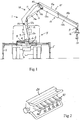
- Fig 1 shows a hydraulic crane 1 mounted on a frame 2, which for instance can be connected to the chassis 3 of a lorry 4.
- the frame 2 is provided with adjustable support legs 5 for supporting the crane 1.
- the crane 1 comprises:
- the lifting cylinder 12 comprises a cylinder part 12a which is articulately connected to the column 7, and a piston which is received in the cylinder part 12a and displaceable in relation to it, wherein the piston is fixed to a piston rod 12b which is articulately connected to the inner boom 11.
- the outer boom cylinder 14 comprises a cylinder part 14a which is articulately connected to the inner boom 11, and a piston which is received in the cylinder part 14a and displaceable in relation to it, wherein the piston is fixed a piston rod 14b which is articulately connected to the outer boom 13.
- the crane boom system 10 of the crane 1 is formed by the inner boom 11 and the outer boom 13 and the associated hydraulic cylinders.
- the crane boom system 10 of the crane 1 may also include more than two liftable and lowerable crane booms articulately connected to each other.
- a liftable and lowerable crane boom in the form of a so-called jib may be mounted to the outer end of the outer boom 13 to thereby make it possible to perform lifting operations requiring a greater range.
- the outer boom 13 is telescopically extensible to enable an adjustment of the extension length L thereof.
- the outer boom 13 comprises one telescopic crane boom section 13b, which is slidably received in a base section 13a of the outer boom 13 and displaceable in the longitudinal direction of the base section 13a for adjustment of the extension length L of the outer boom 13.
- the telescopic crane boom section 13b is displaceable in relation to the base section 13a by means of a hydraulic cylinder 15 carried by the outer boom 13.
- this hydraulic cylinder 15 comprises a cylinder part 15a which is fixed to the base section 13a, and a piston which is received in the cylinder part 15a and displaceable in relation to it, wherein the piston is fixed to a piston rod 15b which is fixed to the telescopic crane boom section 13b.
- the outer boom 13 could comprise two or more telescopic crane boom sections 13b which are mutually slidable in relation to each other in the longitudinal direction of the outer boom 13 for adjustment of the extension length thereof.
- a rotator 16 is articulately fastened to a load suspension point P at the outer end of the outer boom 13, which rotator in its turn carries a lifting hook 17.
- the load to be carried by the crane 1 is fixed to the lifting hook 17, for instance by means of lifting wires or the similar.
- any other suitable type of lifting tool may be connected to the load suspension point P at the outer end of the crane boom system.
- the control system for controlling the hydraulic cylinders 12, 14, 15 of the crane boom system 10 comprises a pump 20 (see Fig 5 ) which pumps hydraulic fluid from a reservoir 21 to a directional-control-valve block 22.
- the directional-control-valve block 22 comprises a directional-control-valve section 23 for each of the hydraulic cylinders 12, 14 and 15 of the crane boom system 10, to which hydraulic cylinders hydraulic fluid is supplied in a conventional manner in dependence on the setting position of the slide member in the respective directional-control-valve section 23.
- the crane 1 comprises a manoeuvring unit 24 (see Fig 2 ) with one or more maneuvering members S1-S6 configured to be manoeuvrable by a crane operator in order to control the position of the load suspension point P of the crane boom system 10.
- Control signals are transmitted via cable or a wireless connection from the manoeuvring unit 24 to an electronic control device 25, for instance in the form of a microprocessor, which in its turn controls the setting position of the slide members in the valve sections 23 of the directional-control-valve block 22 in dependence on control signals from the manoeuvring unit 24 related to the manoeuvring of the maneuvering members S1-S6.
- the electronic control device 25 is configured to control the crane boom movements on the basis of the control signals from the manoeuvring unit 24 and a calculation model for boom tip control.
- the calculation model may for instance be stored as an algorithm in a memory of the electronic control device 25.
- a first maneuvering member S1 may be used for controlling the rotation of the column 7 in relation to the crane base 6 about the vertical axis of rotation A1
- a second maneuvering member S2 may be used for controlling the movement of the load suspension point P in the vertical direction
- a third maneuvering member S3 may be used for controlling the movement of the load suspension point P in the horizontal direction.
- the manoeuvring unit 24 could as an alternative be provided with a joystick to be used for controlling the movement of the load suspension point P in the vertical and horizontal directions.
- a first maneuvering member S1 may be used for controlling the rotation of the column 7 in relation to the crane base 6 about the vertical axis of rotation A1
- a second maneuvering member S2 may be used for controlling the lifting cylinder 12
- a third maneuvering member S3 may be used for controlling the outer boom cylinder 14
- a fourth maneuvering member S4 may be used for controlling the hydraulic cylinder 15.
- Each individual directional-control-valve section 23 controls the magnitude and the direction of the flow of hydraulic fluid to a specific hydraulic cylinder 12, 14, 15 and thereby controls a specific crane function. For the sake of clarity, only the directional-control-valve section 23 for the lifting cylinder 12 is illustrated in Fig 5 .
- the directional-control-valve block 22 further comprises a shunt valve 26, which pumps excessive hydraulic fluid back to the reservoir 21, and an electrically controlled dump valve 27, which can be made to return the entire hydraulic flow from the pump 20 directly back to the reservoir 21.
- the directional-control-valve block 22 is of load-sensing and pressure-compensating type, which implies that the magnitude of the hydraulic flow supplied to a hydraulic cylinder is always proportional to the position of the slide member in the corresponding directional-control-valve section 23.
- the directional-control-valve section 23 comprises a pressure limiter 28, a pressure compensator 29 and a directional-control-valve 30.
- Directional-control-valve blocks and directional-control-valve sections of this type are known and available on the market. Also other types of valve devices then the one here described may of course be used in a crane according to the present invention.
- a load holding valve 31 is arranged between the respective hydraulic cylinder 12, 14, 15 and the associated directional-control-valve section 23, which load holding valve makes sure that the load will remain hanging when the hydraulic system runs out of pressure when the dump valve 27 is made to return the entire hydraulic flow from the pump 20 directly back to the reservoir 21.
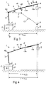
- Sensors 41, 42, 43, 44 are connected to the electronic control device 25 and configured to establish values of variables ⁇ , ⁇ , L, ⁇ (see Fig 3 ) which are related to the prevailing position of the crane booms 11, 13 of the crane boom system 10, and the electronic control device 25 is configured to continuously establish position information as to the prevailing position of the load suspension point P of the crane boom system 10 in relation to the vertical axis of rotation A1 based on the values of these variables ⁇ , B, L, ⁇ .
- said variables comprise:
- the swing-out angle ⁇ of the inner boom 11 is defined as the angle between the longitudinal axis of the inner boom 11 and the horizontal plane
- the swing-out angle ⁇ of the outer boom 13 is defined as the angle between the longitudinal axis of the outer boom 13 and the longitudinal axis of the inner boom 11.
- the swing-out angle ⁇ of the inner boom 11 may for instance be established by means of a sensor 41 which continuously senses the position of the piston rod 12b in relation to the cylinder part 12a of the lifting cylinder 12, whereas the swing-out angle ⁇ of the outer boom 13 may be established by means of a sensor 42 which continuously senses the position of the piston rod 14b in relation to the cylinder part 14a of the outer boom cylinder 14.
- the swing-out angle ⁇ is a function of the extension position of the piston rod 12b of the lifting cylinder 12
- the swing-out angle ⁇ is a function of the extension position of the piston rod 14b of the outer boom cylinder 14.
- these swing-out angles ⁇ , ⁇ could be established by means of suitable angle sensors, which directly sense the respective swing-out angle.
- the extension length L of the outer boom 13 may for instance be established by means of a sensor 43 which continuously senses the position of the piston rod 15b in relation to the cylinder part 15a of the hydraulic cylinder 15.
- the extension length L could be established by means of a measuring device comprising an ultrasonic transmitter and an ultrasonic receiver of the type described in US 5 877 693 A or by means of any other suitable measuring device.
- the slewing angle ⁇ of the column 7 in relation to the crane base 6 is established by means of a sensor 44 which continuously senses the slewing position of the column.
- the electronic control device 25 is connected to the above-mentioned sensors 41, 42, 43, 44 in order to receive measuring signals from these sensors related to the swing-out angle ⁇ , the swing-out angle ⁇ , the extension length L and the slewing angle ⁇ .
- the electronic control device 25 is configured to prevent an execution of crane boom movements that would make the lifting moment of the crane 1 exceed a lifting moment maximum value M max representing a maximum allowed value for the lifting moment of the crane 1.
- a lifting moment maximum value M max representing a maximum allowed value for the lifting moment of the crane 1.
- the electronic control device 25 is configured to prevent the execution of any combination of crane boom movements that would increase the lifting radius r (see Fig 3 ), i.e. the horizontal distance between the load suspension point P and the above-mentioned vertical axis of rotation A1, and allow the execution of any combination of crane boom movements that keeps lifting radius r unchanged or reduces the lifting radius r.
- the electronic control device 25 prevents the load suspension point P from being moved in a direction which would increase the lifting radius r and at the same time allows any other movement of the load suspension point P.
- the position of the inner boom 11 and the outer boom 13 in a situation when the lifting moment of the crane 1 has reached the limit value M limit is illustrated by continuous lines in Fig 3 .
- the lifting radius r reached in this situation is indicated as r limit in Figs 3 and 4 .
- the crane operator may move the load 9 directly downwards from the position illustrated with continuous lines in Fig 3 to the position illustrated with broken lines in Fig 3 .
- the crane operator may consequently put down the load 9 on a spot directly below the point reached by the load suspension point P in the situation when the lifting moment of the crane 1 reached the limit value M limit .
- the limit value M limit preferably corresponds to a predetermined percentage of the lifting moment maximum value M max .
- the limit value M limit may for instance lie within an interval corresponding to 95-99%, preferably 98-99%, of the lifting moment maximum value M max .
- first and second operating modes Two different operating modes, in the following denominated first and second operating modes, are with advantage provided for the electronic control device 25.
- the electronic control device 25 is configured, when it has established that the lifting moment of the crane has reached the limit value M limit , to prevent the execution of any combination of crane boom movements that would increase the lifting radius r and allow the execution of any combination of crane boom movements that keeps the lifting radius r unchanged or reduces the lifting radius r and allow the execution of any combination of crane boom movements that keeps the lifting radius r unchanged or reduces the lifting radius r.
- the electronic control device 25 is configured to stop presently executed crane boom movements when it has been established by the electronic control device 25 that the lifting moment of the crane has reached the lifting moment maximum value M max , and only allow such a stop to be followed by an execution of a combination of crane boom movements that reduces the lifting radius r.
- the crane 1 comprises switching means, for instance in the form of a maneuvering member S6 on the manoeuvring unit 24, by means of which the crane operator may switch from the first operating mode to the second operating mode.
- the lifting radius r that may be reached in the first operating mode is indicated as r limit in Fig 4
- the lifting radius r that may be reached in the second operating mode is indicated as r max in Fig 4 .
- the electronic control device 25 is with advantage, in a conventional manner, adapted to convert the prevailing limit value M limit and lifting moment maximum value M max , respectively, into a corresponding value for the maximum allowed working pressure for the lifting cylinder 12.
- the crane 1 comprises a pressure sensor 32 which is arranged to measure the hydraulic pressure on the piston side of the lifting cylinder 12.
- the electronic control device 25 is connected to the pressure sensor 32 in order to receive measuring signals from this sensor related to said hydraulic pressure.
- the electronic control device 25 continuously reads the output signals from the pressure sensor 32 and compares the output signal from the pressure sensor with the established value of the maximum allowed working pressure for the lifting cylinder 12.
- the electronic control device 25 delivers a signal to the dump valve 27, which dumps the hydraulic flow directly to the reservoir 21, which results in that the hydraulic system runs out of pressure and that the presently executed crane boom movements are stopped. In this situation, the load 9 is held by means of the load holding valve 31.
- the electronic control device 25 is configured to let the maximum allowed working pressure for the lifting cylinder 12 represent the maximum allowed hydraulic pressure on the piston side of the lifting cylinder.
- the electronic control device 25 could alternatively be configured to let the maximum allowed working pressure for the lifting cylinder 12 represent the maximum allowed differential pressure in the lifting cylinder. This differential pressure is defined as the hydraulic pressure on the piston side of the lifting cylinder minus the hydraulic pressure on its piston rod side divided by the cylinder ratio.
- the electronic control device 25 is also arranged to receive measuring signals from a pressure sensor which measures the hydraulic pressure on the piston rod side of the lifting cylinder 12 so as to thereby be able to establish the prevailing differential pressure of the lifting cylinder and compare this differential pressure with the established value of the maximum allowed working pressure for the lifting cylinder.
- working pressure as used in this description consequently refers either to the hydraulic pressure on the piston side of a hydraulic cylinder or the differential pressure in a hydraulic cylinder.
- the electronic control device 25 may be implemented by one single electronic control unit, as illustrated in Fig 5 . However, the electronic control device 25 could as an alternative be implemented by two or more mutually co-operating electronic control units.
- control system of the crane may for instance have another design than the control system which is illustrated in Fig 5 and described above.
- the crane boom system of the crane could have another design than the crane boom system which is illustrated in Figs 1 , 3 , 4 and 5 and described above.
Landscapes
- Engineering & Computer Science (AREA)
- Mechanical Engineering (AREA)
- Automation & Control Theory (AREA)
- Jib Cranes (AREA)
Priority Applications (7)
| Application Number | Priority Date | Filing Date | Title |
|---|---|---|---|
| DK16166896.7T DK3239092T3 (da) | 2016-04-25 | 2016-04-25 | Hydraulisk kran |
| EP16166896.7A EP3239092B1 (de) | 2016-04-25 | 2016-04-25 | Hydraulikkran |
| EP19168596.5A EP3549899A1 (de) | 2016-04-25 | 2016-04-25 | Hydraulikkran |
| CN201780025790.0A CN109071191B (zh) | 2016-04-25 | 2017-04-20 | 液压起重机 |
| CA3021713A CA3021713C (en) | 2016-04-25 | 2017-04-20 | Hydraulic crane |
| US16/095,832 US11591190B2 (en) | 2016-04-25 | 2017-04-20 | Hydraulic crane |
| PCT/EP2017/059323 WO2017186549A1 (en) | 2016-04-25 | 2017-04-20 | Hydraulic crane |
Applications Claiming Priority (1)
| Application Number | Priority Date | Filing Date | Title |
|---|---|---|---|
| EP16166896.7A EP3239092B1 (de) | 2016-04-25 | 2016-04-25 | Hydraulikkran |
Related Child Applications (2)
| Application Number | Title | Priority Date | Filing Date |
|---|---|---|---|
| EP19168596.5A Division-Into EP3549899A1 (de) | 2016-04-25 | 2016-04-25 | Hydraulikkran |
| EP19168596.5A Division EP3549899A1 (de) | 2016-04-25 | 2016-04-25 | Hydraulikkran |
Publications (2)
| Publication Number | Publication Date |
|---|---|
| EP3239092A1 true EP3239092A1 (de) | 2017-11-01 |
| EP3239092B1 EP3239092B1 (de) | 2019-06-05 |
Family
ID=55808513
Family Applications (2)
| Application Number | Title | Priority Date | Filing Date |
|---|---|---|---|
| EP16166896.7A Active EP3239092B1 (de) | 2016-04-25 | 2016-04-25 | Hydraulikkran |
| EP19168596.5A Withdrawn EP3549899A1 (de) | 2016-04-25 | 2016-04-25 | Hydraulikkran |
Family Applications After (1)
| Application Number | Title | Priority Date | Filing Date |
|---|---|---|---|
| EP19168596.5A Withdrawn EP3549899A1 (de) | 2016-04-25 | 2016-04-25 | Hydraulikkran |
Country Status (6)
| Country | Link |
|---|---|
| US (1) | US11591190B2 (de) |
| EP (2) | EP3239092B1 (de) |
| CN (1) | CN109071191B (de) |
| CA (1) | CA3021713C (de) |
| DK (1) | DK3239092T3 (de) |
| WO (1) | WO2017186549A1 (de) |
Cited By (2)
| Publication number | Priority date | Publication date | Assignee | Title |
|---|---|---|---|---|
| EP3725727A1 (de) * | 2019-04-18 | 2020-10-21 | Deere & Company | Steuerungssystem für einen kran einer arbeitsmaschine, verfahren und arbeitsmaschine |
| EP3556710B1 (de) * | 2018-04-19 | 2023-01-11 | FASSI GRU S.p.A. | Kran mit gelenkarm |
Families Citing this family (4)
| Publication number | Priority date | Publication date | Assignee | Title |
|---|---|---|---|---|
| EP3431435B1 (de) * | 2017-07-17 | 2020-04-22 | Manitou Bf | Steuerung einer fördermaschine |
| EP3670426B1 (de) * | 2018-12-21 | 2021-10-06 | Hiab AB | Mobile arbeitsmaschine und verfahren zur überwachung der bedienung von stabilisatorbeinen in einer mobilen arbeitsmaschine |
| CN113028250B (zh) * | 2021-04-12 | 2022-07-01 | 珠海市润星泰电器有限公司 | 一种显示屏推车 |
| US20250276877A1 (en) * | 2024-03-01 | 2025-09-04 | Palfinger Ag | Control circuitry for a crane, crane, winch arrangement for a crane, remote control unit for a crane and method to operate a crane |
Citations (5)
| Publication number | Priority date | Publication date | Assignee | Title |
|---|---|---|---|---|
| GB2078197A (en) | 1980-06-04 | 1982-01-06 | Hiab Foco Ab | Load limiting device |
| DE3145719A1 (de) * | 1980-11-28 | 1982-06-24 | Fratelli Ferrari S.n.c., Boretto, Emilia | "vorrichtung zur momentbegrenzung fuer kraene mit gelenkauslegern, besonders solche, die zur montage auf lastwagen vorgesehen sind" |
| US5877693A (en) | 1998-05-27 | 1999-03-02 | Grove U.S. L.L.C. | Method and apparatus for measuring the length of a multi-section telescopic boom |
| WO2008143584A1 (en) * | 2007-05-23 | 2008-11-27 | Cargotec Patenter Ab | Hydraulic crane and a method for regulating the maximum allowed working pressure in such a crane |
| EP2298689A2 (de) * | 2009-09-22 | 2011-03-23 | Cargotec Patenter AB | Verfahren und Vorrichtung zur Lastmomentbegrenzung eines Ladekrans |
Family Cites Families (9)
| Publication number | Priority date | Publication date | Assignee | Title |
|---|---|---|---|---|
| DE1260734B (de) * | 1965-08-06 | 1968-02-08 | Forslund & Co Fabriks Ab | Fahrzeugkran |
| DE2164628C3 (de) * | 1971-12-24 | 1978-03-16 | Siegfried Dipl.-Ing. Dr.-Ing. 4930 Detmold Gross | Überlastabschalteinrichtung für hintereinandergekoppelte hydraulische Hubbzw. Verstellmechanismen |
| US3963127A (en) * | 1972-05-02 | 1976-06-15 | Hiab-Foco Aktiebolag | Blocking arrangement in hydraulically operated cranes |
| US4411368A (en) * | 1980-03-21 | 1983-10-25 | Roger Manjot | Safety system for hydraulically controlled hoisting apparatus |
| ES2194560B1 (es) * | 2000-07-11 | 2005-03-01 | Partek Cargotec, S.A. | Cilindro hidraulico para brazos telescopicos. |
| AT12086U1 (de) * | 2010-06-17 | 2011-10-15 | Palfinger Ag | Fahrzeugkran |
| DE102012004914A1 (de) * | 2012-03-09 | 2013-09-12 | Liebherr-Werk Nenzing Gmbh | Kransteuerung mit Seilkraftmodus |
| CN102910534B (zh) * | 2012-10-18 | 2014-12-24 | 中国人民解放军总后勤部建筑工程研究所 | 一种用于折臂式随车起重机的直线起吊装置及其控制方法 |
| CN105084213B (zh) * | 2015-07-06 | 2017-05-10 | 中联重科股份有限公司 | 移动式起重机及其力矩限制系统、力矩限制方法 |
-
2016
- 2016-04-25 EP EP16166896.7A patent/EP3239092B1/de active Active
- 2016-04-25 EP EP19168596.5A patent/EP3549899A1/de not_active Withdrawn
- 2016-04-25 DK DK16166896.7T patent/DK3239092T3/da active
-
2017
- 2017-04-20 CN CN201780025790.0A patent/CN109071191B/zh not_active Expired - Fee Related
- 2017-04-20 US US16/095,832 patent/US11591190B2/en active Active
- 2017-04-20 CA CA3021713A patent/CA3021713C/en active Active
- 2017-04-20 WO PCT/EP2017/059323 patent/WO2017186549A1/en not_active Ceased
Patent Citations (5)
| Publication number | Priority date | Publication date | Assignee | Title |
|---|---|---|---|---|
| GB2078197A (en) | 1980-06-04 | 1982-01-06 | Hiab Foco Ab | Load limiting device |
| DE3145719A1 (de) * | 1980-11-28 | 1982-06-24 | Fratelli Ferrari S.n.c., Boretto, Emilia | "vorrichtung zur momentbegrenzung fuer kraene mit gelenkauslegern, besonders solche, die zur montage auf lastwagen vorgesehen sind" |
| US5877693A (en) | 1998-05-27 | 1999-03-02 | Grove U.S. L.L.C. | Method and apparatus for measuring the length of a multi-section telescopic boom |
| WO2008143584A1 (en) * | 2007-05-23 | 2008-11-27 | Cargotec Patenter Ab | Hydraulic crane and a method for regulating the maximum allowed working pressure in such a crane |
| EP2298689A2 (de) * | 2009-09-22 | 2011-03-23 | Cargotec Patenter AB | Verfahren und Vorrichtung zur Lastmomentbegrenzung eines Ladekrans |
Cited By (3)
| Publication number | Priority date | Publication date | Assignee | Title |
|---|---|---|---|---|
| EP3556710B1 (de) * | 2018-04-19 | 2023-01-11 | FASSI GRU S.p.A. | Kran mit gelenkarm |
| EP3725727A1 (de) * | 2019-04-18 | 2020-10-21 | Deere & Company | Steuerungssystem für einen kran einer arbeitsmaschine, verfahren und arbeitsmaschine |
| EP3725728A1 (de) * | 2019-04-18 | 2020-10-21 | Deere & Company | Steuersystem zur steuerung einer krananlage, verfahren zur steuerung einer krananlage und arbeitsfahrzeug |
Also Published As
| Publication number | Publication date |
|---|---|
| US20210229965A1 (en) | 2021-07-29 |
| CN109071191B (zh) | 2020-03-27 |
| WO2017186549A1 (en) | 2017-11-02 |
| US11591190B2 (en) | 2023-02-28 |
| CA3021713C (en) | 2024-07-02 |
| CN109071191A (zh) | 2018-12-21 |
| DK3239092T3 (da) | 2019-09-02 |
| CA3021713A1 (en) | 2017-11-02 |
| EP3239092B1 (de) | 2019-06-05 |
| EP3549899A1 (de) | 2019-10-09 |
Similar Documents
| Publication | Publication Date | Title |
|---|---|---|
| EP3257805B1 (de) | Hydraulikkran | |
| US11591190B2 (en) | Hydraulic crane | |
| EP2298689B1 (de) | Verfahren und Vorrichtung zur Lastmomentbegrenzung eines Ladekrans | |
| US8272521B1 (en) | Crane moment load and load delivery system control and method | |
| US8160786B2 (en) | Mobile crane and method for operating a mobile crane | |
| US11174138B2 (en) | Mobile working machine and method for supervising the manoeuvring of stabilizer legs included in a mobile working machine | |
| US9845588B2 (en) | Hydraulic control system for controlling a moveable device | |
| US5538149A (en) | Control systems for the lifting moment of vehicle mounted booms | |
| CN107848774A (zh) | 起重机控制装置 | |
| WO2008143584A1 (en) | Hydraulic crane and a method for regulating the maximum allowed working pressure in such a crane | |
| EP3812338B1 (de) | Lastkraftwagen und verfahren zur regelung des maximal zulässigen hubmoments eines hydraulischen lastkraftwagenkrans | |
| JP7088418B2 (ja) | 過負荷防止装置 | |
| JP3258471B2 (ja) | クレーンまたはタワークレーンの過負荷防止装置 | |
| JP7151908B2 (ja) | 過負荷防止装置 | |
| EP4516091B1 (de) | Ladesystem für ein landwirtschaftsarbeitsfahrzeug | |
| JP4988990B2 (ja) | クレーンのジブ起伏制御装置 | |
| JPH01256497A (ja) | 伸縮ブームを有するクレーンの吊荷地切時荷振防止装置 | |
| JP2022180140A (ja) | アースドリル機およびアースドリル機用の表示装置 | |
| JP2021143051A (ja) | 作業車両 |
Legal Events
| Date | Code | Title | Description |
|---|---|---|---|
| PUAI | Public reference made under article 153(3) epc to a published international application that has entered the european phase |
Free format text: ORIGINAL CODE: 0009012 |
|
| STAA | Information on the status of an ep patent application or granted ep patent |
Free format text: STATUS: THE APPLICATION HAS BEEN PUBLISHED |
|
| AK | Designated contracting states |
Kind code of ref document: A1 Designated state(s): AL AT BE BG CH CY CZ DE DK EE ES FI FR GB GR HR HU IE IS IT LI LT LU LV MC MK MT NL NO PL PT RO RS SE SI SK SM TR |
|
| AX | Request for extension of the european patent |
Extension state: BA ME |
|
| STAA | Information on the status of an ep patent application or granted ep patent |
Free format text: STATUS: REQUEST FOR EXAMINATION WAS MADE |
|
| 17P | Request for examination filed |
Effective date: 20180425 |
|
| RBV | Designated contracting states (corrected) |
Designated state(s): AL AT BE BG CH CY CZ DE DK EE ES FI FR GB GR HR HU IE IS IT LI LT LU LV MC MK MT NL NO PL PT RO RS SE SI SK SM TR |
|
| GRAP | Despatch of communication of intention to grant a patent |
Free format text: ORIGINAL CODE: EPIDOSNIGR1 |
|
| STAA | Information on the status of an ep patent application or granted ep patent |
Free format text: STATUS: GRANT OF PATENT IS INTENDED |
|
| INTG | Intention to grant announced |
Effective date: 20181029 |
|
| GRAS | Grant fee paid |
Free format text: ORIGINAL CODE: EPIDOSNIGR3 |
|
| GRAJ | Information related to disapproval of communication of intention to grant by the applicant or resumption of examination proceedings by the epo deleted |
Free format text: ORIGINAL CODE: EPIDOSDIGR1 |
|
| GRAL | Information related to payment of fee for publishing/printing deleted |
Free format text: ORIGINAL CODE: EPIDOSDIGR3 |
|
| STAA | Information on the status of an ep patent application or granted ep patent |
Free format text: STATUS: REQUEST FOR EXAMINATION WAS MADE |
|
| GRAR | Information related to intention to grant a patent recorded |
Free format text: ORIGINAL CODE: EPIDOSNIGR71 |
|
| STAA | Information on the status of an ep patent application or granted ep patent |
Free format text: STATUS: GRANT OF PATENT IS INTENDED |
|
| INTC | Intention to grant announced (deleted) | ||
| INTG | Intention to grant announced |
Effective date: 20190320 |
|
| GRAA | (expected) grant |
Free format text: ORIGINAL CODE: 0009210 |
|
| STAA | Information on the status of an ep patent application or granted ep patent |
Free format text: STATUS: THE PATENT HAS BEEN GRANTED |
|
| AK | Designated contracting states |
Kind code of ref document: B1 Designated state(s): AL AT BE BG CH CY CZ DE DK EE ES FI FR GB GR HR HU IE IS IT LI LT LU LV MC MK MT NL NO PL PT RO RS SE SI SK SM TR |
|
| REG | Reference to a national code |
Ref country code: GB Ref legal event code: FG4D |
|
| REG | Reference to a national code |
Ref country code: CH Ref legal event code: EP |
|
| REG | Reference to a national code |
Ref country code: AT Ref legal event code: REF Ref document number: 1139798 Country of ref document: AT Kind code of ref document: T Effective date: 20190615 |
|
| REG | Reference to a national code |
Ref country code: DE Ref legal event code: R096 Ref document number: 602016014711 Country of ref document: DE |
|
| REG | Reference to a national code |
Ref country code: IE Ref legal event code: FG4D |
|
| RAP2 | Party data changed (patent owner data changed or rights of a patent transferred) |
Owner name: CARGOTEC PATENTER AB |
|
| REG | Reference to a national code |
Ref country code: DK Ref legal event code: T3 Effective date: 20190827 |
|
| REG | Reference to a national code |
Ref country code: NL Ref legal event code: MP Effective date: 20190605 |
|
| REG | Reference to a national code |
Ref country code: LT Ref legal event code: MG4D |
|
| PG25 | Lapsed in a contracting state [announced via postgrant information from national office to epo] |
Ref country code: SE Free format text: LAPSE BECAUSE OF FAILURE TO SUBMIT A TRANSLATION OF THE DESCRIPTION OR TO PAY THE FEE WITHIN THE PRESCRIBED TIME-LIMIT Effective date: 20190605 Ref country code: HR Free format text: LAPSE BECAUSE OF FAILURE TO SUBMIT A TRANSLATION OF THE DESCRIPTION OR TO PAY THE FEE WITHIN THE PRESCRIBED TIME-LIMIT Effective date: 20190605 Ref country code: AL Free format text: LAPSE BECAUSE OF FAILURE TO SUBMIT A TRANSLATION OF THE DESCRIPTION OR TO PAY THE FEE WITHIN THE PRESCRIBED TIME-LIMIT Effective date: 20190605 Ref country code: FI Free format text: LAPSE BECAUSE OF FAILURE TO SUBMIT A TRANSLATION OF THE DESCRIPTION OR TO PAY THE FEE WITHIN THE PRESCRIBED TIME-LIMIT Effective date: 20190605 Ref country code: NO Free format text: LAPSE BECAUSE OF FAILURE TO SUBMIT A TRANSLATION OF THE DESCRIPTION OR TO PAY THE FEE WITHIN THE PRESCRIBED TIME-LIMIT Effective date: 20190905 Ref country code: LT Free format text: LAPSE BECAUSE OF FAILURE TO SUBMIT A TRANSLATION OF THE DESCRIPTION OR TO PAY THE FEE WITHIN THE PRESCRIBED TIME-LIMIT Effective date: 20190605 Ref country code: ES Free format text: LAPSE BECAUSE OF FAILURE TO SUBMIT A TRANSLATION OF THE DESCRIPTION OR TO PAY THE FEE WITHIN THE PRESCRIBED TIME-LIMIT Effective date: 20190605 |
|
| PG25 | Lapsed in a contracting state [announced via postgrant information from national office to epo] |
Ref country code: GR Free format text: LAPSE BECAUSE OF FAILURE TO SUBMIT A TRANSLATION OF THE DESCRIPTION OR TO PAY THE FEE WITHIN THE PRESCRIBED TIME-LIMIT Effective date: 20190906 Ref country code: RS Free format text: LAPSE BECAUSE OF FAILURE TO SUBMIT A TRANSLATION OF THE DESCRIPTION OR TO PAY THE FEE WITHIN THE PRESCRIBED TIME-LIMIT Effective date: 20190605 Ref country code: BG Free format text: LAPSE BECAUSE OF FAILURE TO SUBMIT A TRANSLATION OF THE DESCRIPTION OR TO PAY THE FEE WITHIN THE PRESCRIBED TIME-LIMIT Effective date: 20190905 Ref country code: LV Free format text: LAPSE BECAUSE OF FAILURE TO SUBMIT A TRANSLATION OF THE DESCRIPTION OR TO PAY THE FEE WITHIN THE PRESCRIBED TIME-LIMIT Effective date: 20190605 |
|
| PG25 | Lapsed in a contracting state [announced via postgrant information from national office to epo] |
Ref country code: NL Free format text: LAPSE BECAUSE OF FAILURE TO SUBMIT A TRANSLATION OF THE DESCRIPTION OR TO PAY THE FEE WITHIN THE PRESCRIBED TIME-LIMIT Effective date: 20190605 Ref country code: EE Free format text: LAPSE BECAUSE OF FAILURE TO SUBMIT A TRANSLATION OF THE DESCRIPTION OR TO PAY THE FEE WITHIN THE PRESCRIBED TIME-LIMIT Effective date: 20190605 Ref country code: CZ Free format text: LAPSE BECAUSE OF FAILURE TO SUBMIT A TRANSLATION OF THE DESCRIPTION OR TO PAY THE FEE WITHIN THE PRESCRIBED TIME-LIMIT Effective date: 20190605 Ref country code: RO Free format text: LAPSE BECAUSE OF FAILURE TO SUBMIT A TRANSLATION OF THE DESCRIPTION OR TO PAY THE FEE WITHIN THE PRESCRIBED TIME-LIMIT Effective date: 20190605 Ref country code: SK Free format text: LAPSE BECAUSE OF FAILURE TO SUBMIT A TRANSLATION OF THE DESCRIPTION OR TO PAY THE FEE WITHIN THE PRESCRIBED TIME-LIMIT Effective date: 20190605 Ref country code: PT Free format text: LAPSE BECAUSE OF FAILURE TO SUBMIT A TRANSLATION OF THE DESCRIPTION OR TO PAY THE FEE WITHIN THE PRESCRIBED TIME-LIMIT Effective date: 20191007 |
|
| PG25 | Lapsed in a contracting state [announced via postgrant information from national office to epo] |
Ref country code: IS Free format text: LAPSE BECAUSE OF FAILURE TO SUBMIT A TRANSLATION OF THE DESCRIPTION OR TO PAY THE FEE WITHIN THE PRESCRIBED TIME-LIMIT Effective date: 20191005 Ref country code: SM Free format text: LAPSE BECAUSE OF FAILURE TO SUBMIT A TRANSLATION OF THE DESCRIPTION OR TO PAY THE FEE WITHIN THE PRESCRIBED TIME-LIMIT Effective date: 20190605 |
|
| REG | Reference to a national code |
Ref country code: DE Ref legal event code: R097 Ref document number: 602016014711 Country of ref document: DE |
|
| PG25 | Lapsed in a contracting state [announced via postgrant information from national office to epo] |
Ref country code: TR Free format text: LAPSE BECAUSE OF FAILURE TO SUBMIT A TRANSLATION OF THE DESCRIPTION OR TO PAY THE FEE WITHIN THE PRESCRIBED TIME-LIMIT Effective date: 20190605 |
|
| PLBE | No opposition filed within time limit |
Free format text: ORIGINAL CODE: 0009261 |
|
| STAA | Information on the status of an ep patent application or granted ep patent |
Free format text: STATUS: NO OPPOSITION FILED WITHIN TIME LIMIT |
|
| PG25 | Lapsed in a contracting state [announced via postgrant information from national office to epo] |
Ref country code: PL Free format text: LAPSE BECAUSE OF FAILURE TO SUBMIT A TRANSLATION OF THE DESCRIPTION OR TO PAY THE FEE WITHIN THE PRESCRIBED TIME-LIMIT Effective date: 20190605 |
|
| 26N | No opposition filed |
Effective date: 20200306 |
|
| PG25 | Lapsed in a contracting state [announced via postgrant information from national office to epo] |
Ref country code: SI Free format text: LAPSE BECAUSE OF FAILURE TO SUBMIT A TRANSLATION OF THE DESCRIPTION OR TO PAY THE FEE WITHIN THE PRESCRIBED TIME-LIMIT Effective date: 20190605 |
|
| PG25 | Lapsed in a contracting state [announced via postgrant information from national office to epo] |
Ref country code: MC Free format text: LAPSE BECAUSE OF FAILURE TO SUBMIT A TRANSLATION OF THE DESCRIPTION OR TO PAY THE FEE WITHIN THE PRESCRIBED TIME-LIMIT Effective date: 20190605 |
|
| REG | Reference to a national code |
Ref country code: CH Ref legal event code: PL |
|
| PG25 | Lapsed in a contracting state [announced via postgrant information from national office to epo] |
Ref country code: LU Free format text: LAPSE BECAUSE OF NON-PAYMENT OF DUE FEES Effective date: 20200425 Ref country code: CH Free format text: LAPSE BECAUSE OF NON-PAYMENT OF DUE FEES Effective date: 20200430 Ref country code: LI Free format text: LAPSE BECAUSE OF NON-PAYMENT OF DUE FEES Effective date: 20200430 |
|
| REG | Reference to a national code |
Ref country code: BE Ref legal event code: MM Effective date: 20200430 |
|
| PG25 | Lapsed in a contracting state [announced via postgrant information from national office to epo] |
Ref country code: BE Free format text: LAPSE BECAUSE OF NON-PAYMENT OF DUE FEES Effective date: 20200430 |
|
| REG | Reference to a national code |
Ref country code: DE Ref legal event code: R082 Ref document number: 602016014711 Country of ref document: DE Representative=s name: MANITZ FINSTERWALD PATENT- UND RECHTSANWALTSPA, DE Ref country code: DE Ref legal event code: R081 Ref document number: 602016014711 Country of ref document: DE Owner name: HIAB AB, SE Free format text: FORMER OWNER: CARGOTEC PATENTER AB, LJUNGBY, SE |
|
| PG25 | Lapsed in a contracting state [announced via postgrant information from national office to epo] |
Ref country code: IE Free format text: LAPSE BECAUSE OF NON-PAYMENT OF DUE FEES Effective date: 20200425 |
|
| REG | Reference to a national code |
Ref country code: GB Ref legal event code: 732E Free format text: REGISTERED BETWEEN 20210513 AND 20210519 |
|
| REG | Reference to a national code |
Ref country code: AT Ref legal event code: PC Ref document number: 1139798 Country of ref document: AT Kind code of ref document: T Owner name: HIAB AB, SE Effective date: 20210511 |
|
| REG | Reference to a national code |
Ref country code: AT Ref legal event code: UEP Ref document number: 1139798 Country of ref document: AT Kind code of ref document: T Effective date: 20190605 |
|
| PG25 | Lapsed in a contracting state [announced via postgrant information from national office to epo] |
Ref country code: MT Free format text: LAPSE BECAUSE OF FAILURE TO SUBMIT A TRANSLATION OF THE DESCRIPTION OR TO PAY THE FEE WITHIN THE PRESCRIBED TIME-LIMIT Effective date: 20190605 Ref country code: CY Free format text: LAPSE BECAUSE OF FAILURE TO SUBMIT A TRANSLATION OF THE DESCRIPTION OR TO PAY THE FEE WITHIN THE PRESCRIBED TIME-LIMIT Effective date: 20190605 |
|
| PG25 | Lapsed in a contracting state [announced via postgrant information from national office to epo] |
Ref country code: MK Free format text: LAPSE BECAUSE OF FAILURE TO SUBMIT A TRANSLATION OF THE DESCRIPTION OR TO PAY THE FEE WITHIN THE PRESCRIBED TIME-LIMIT Effective date: 20190605 |
|
| P01 | Opt-out of the competence of the unified patent court (upc) registered |
Effective date: 20230506 |
|
| REG | Reference to a national code |
Ref country code: DE Ref legal event code: R081 Ref document number: 602016014711 Country of ref document: DE Owner name: HIAB AB, SE Free format text: FORMER OWNER: HIAB AB, KISTA, SE |
|
| PGFP | Annual fee paid to national office [announced via postgrant information from national office to epo] |
Ref country code: DE Payment date: 20250428 Year of fee payment: 10 |
|
| PGFP | Annual fee paid to national office [announced via postgrant information from national office to epo] |
Ref country code: GB Payment date: 20250422 Year of fee payment: 10 Ref country code: DK Payment date: 20250424 Year of fee payment: 10 |
|
| PGFP | Annual fee paid to national office [announced via postgrant information from national office to epo] |
Ref country code: IT Payment date: 20250422 Year of fee payment: 10 |
|
| PGFP | Annual fee paid to national office [announced via postgrant information from national office to epo] |
Ref country code: FR Payment date: 20250424 Year of fee payment: 10 |
|
| PGFP | Annual fee paid to national office [announced via postgrant information from national office to epo] |
Ref country code: AT Payment date: 20250417 Year of fee payment: 10 |