EP3239448A1 - Dispositif d'actionnement pour une porte coulissante de véhicule automobile - Google Patents
Dispositif d'actionnement pour une porte coulissante de véhicule automobile Download PDFInfo
- Publication number
- EP3239448A1 EP3239448A1 EP17168441.8A EP17168441A EP3239448A1 EP 3239448 A1 EP3239448 A1 EP 3239448A1 EP 17168441 A EP17168441 A EP 17168441A EP 3239448 A1 EP3239448 A1 EP 3239448A1
- Authority
- EP
- European Patent Office
- Prior art keywords
- door
- motor vehicle
- guide rail
- driver element
- actuating device
- Prior art date
- Legal status (The legal status is an assumption and is not a legal conclusion. Google has not performed a legal analysis and makes no representation as to the accuracy of the status listed.)
- Withdrawn
Links
Images



Classifications
-
- E—FIXED CONSTRUCTIONS
- E05—LOCKS; KEYS; WINDOW OR DOOR FITTINGS; SAFES
- E05F—DEVICES FOR MOVING WINGS INTO OPEN OR CLOSED POSITION; CHECKS FOR WINGS; WING FITTINGS NOT OTHERWISE PROVIDED FOR, CONCERNED WITH THE FUNCTIONING OF THE WING
- E05F15/00—Power-operated mechanisms for wings
- E05F15/60—Power-operated mechanisms for wings using electrical actuators
- E05F15/603—Power-operated mechanisms for wings using electrical actuators using rotary electromotors
- E05F15/632—Power-operated mechanisms for wings using electrical actuators using rotary electromotors for horizontally-sliding wings
- E05F15/643—Power-operated mechanisms for wings using electrical actuators using rotary electromotors for horizontally-sliding wings operated by flexible elongated pulling elements, e.g. belts, chains or cables
- E05F15/646—Power-operated mechanisms for wings using electrical actuators using rotary electromotors for horizontally-sliding wings operated by flexible elongated pulling elements, e.g. belts, chains or cables allowing or involving a secondary movement of the wing, e.g. rotational or transversal
-
- E—FIXED CONSTRUCTIONS
- E05—LOCKS; KEYS; WINDOW OR DOOR FITTINGS; SAFES
- E05F—DEVICES FOR MOVING WINGS INTO OPEN OR CLOSED POSITION; CHECKS FOR WINGS; WING FITTINGS NOT OTHERWISE PROVIDED FOR, CONCERNED WITH THE FUNCTIONING OF THE WING
- E05F15/00—Power-operated mechanisms for wings
- E05F15/60—Power-operated mechanisms for wings using electrical actuators
- E05F15/603—Power-operated mechanisms for wings using electrical actuators using rotary electromotors
- E05F15/632—Power-operated mechanisms for wings using electrical actuators using rotary electromotors for horizontally-sliding wings
- E05F15/652—Power-operated mechanisms for wings using electrical actuators using rotary electromotors for horizontally-sliding wings operated by screw-and-nut mechanisms
-
- E—FIXED CONSTRUCTIONS
- E05—LOCKS; KEYS; WINDOW OR DOOR FITTINGS; SAFES
- E05F—DEVICES FOR MOVING WINGS INTO OPEN OR CLOSED POSITION; CHECKS FOR WINGS; WING FITTINGS NOT OTHERWISE PROVIDED FOR, CONCERNED WITH THE FUNCTIONING OF THE WING
- E05F15/00—Power-operated mechanisms for wings
- E05F15/60—Power-operated mechanisms for wings using electrical actuators
- E05F15/603—Power-operated mechanisms for wings using electrical actuators using rotary electromotors
- E05F15/632—Power-operated mechanisms for wings using electrical actuators using rotary electromotors for horizontally-sliding wings
- E05F15/655—Power-operated mechanisms for wings using electrical actuators using rotary electromotors for horizontally-sliding wings specially adapted for vehicle wings
-
- E—FIXED CONSTRUCTIONS
- E05—LOCKS; KEYS; WINDOW OR DOOR FITTINGS; SAFES
- E05Y—INDEXING SCHEME ASSOCIATED WITH SUBCLASSES E05D AND E05F, RELATING TO CONSTRUCTION ELEMENTS, ELECTRIC CONTROL, POWER SUPPLY, POWER SIGNAL OR TRANSMISSION, USER INTERFACES, MOUNTING OR COUPLING, DETAILS, ACCESSORIES, AUXILIARY OPERATIONS NOT OTHERWISE PROVIDED FOR, APPLICATION THEREOF
- E05Y2201/00—Constructional elements; Accessories therefor
- E05Y2201/20—Brakes; Disengaging means; Holders; Stops; Valves; Accessories therefor
- E05Y2201/214—Disengaging means
-
- E—FIXED CONSTRUCTIONS
- E05—LOCKS; KEYS; WINDOW OR DOOR FITTINGS; SAFES
- E05Y—INDEXING SCHEME ASSOCIATED WITH SUBCLASSES E05D AND E05F, RELATING TO CONSTRUCTION ELEMENTS, ELECTRIC CONTROL, POWER SUPPLY, POWER SIGNAL OR TRANSMISSION, USER INTERFACES, MOUNTING OR COUPLING, DETAILS, ACCESSORIES, AUXILIARY OPERATIONS NOT OTHERWISE PROVIDED FOR, APPLICATION THEREOF
- E05Y2900/00—Application of doors, windows, wings or fittings thereof
- E05Y2900/50—Application of doors, windows, wings or fittings thereof for vehicles
-
- E—FIXED CONSTRUCTIONS
- E05—LOCKS; KEYS; WINDOW OR DOOR FITTINGS; SAFES
- E05Y—INDEXING SCHEME ASSOCIATED WITH SUBCLASSES E05D AND E05F, RELATING TO CONSTRUCTION ELEMENTS, ELECTRIC CONTROL, POWER SUPPLY, POWER SIGNAL OR TRANSMISSION, USER INTERFACES, MOUNTING OR COUPLING, DETAILS, ACCESSORIES, AUXILIARY OPERATIONS NOT OTHERWISE PROVIDED FOR, APPLICATION THEREOF
- E05Y2900/00—Application of doors, windows, wings or fittings thereof
- E05Y2900/50—Application of doors, windows, wings or fittings thereof for vehicles
- E05Y2900/53—Type of wing
- E05Y2900/531—Doors
Definitions
- the invention relates to an actuating device for the automatic opening and closing of motor vehicle doors, in particular a sliding door.
- the proposed solution is suitable for the subsequent retrofitting of motor vehicles (motor vehicles) and their sliding doors, which as standard have no actuator for the automatic opening and closing of the door, i. These doors are opened and closed manually.
- Actuators for the automatic opening and closing of motor vehicle sliding doors consist of a drive unit consisting of drive motor, e.g. Electric motor, gearbox and a safety clutches. composed.
- the drive unit is attached to the vehicle side wall.
- the ropes are guided by guides and deflections and driven by a drive wheel which is designed as a reel spool.
- This unit forms the guide unit, this system is also attached to the side wall and thus forms together with the drive unit, the Betätiguns liked.
- the rope or force-transmitting element is with the sliding door connected.
- the sliding door itself is received on the vehicle side or statically via guides and rollers and translationally displaceable.
- the systems are designed in such a way that parts of the guide unit (guides, deflections, levers, etc.) are also mounted or run or guided in the vehicle inside and outside the vehicle. Associated with this are openings or free cuts on the vehicle side wall, the openings must be laboriously sealed against environmental influences such as water, dirt, ice. If these media reach the vehicle interior, they can cause damage, increased wear or malfunction.
- the actuator, in particular retrofit solutions are usually integrated in the middle guide rail of the sliding door.
- the disadvantage here is that the known solutions is significantly reduced in the vehicle structure, supporting components by these are trimmed to mount the mechanics of the mounting solutions in the vehicle interior and place, this is injured by the lintels supporting component structures, these measures affect the crash safety of the vehicle negative.
- the invention has for its object to propose an actuator, which allows flexible use for automatic operation of sliding doors.
- the very simple and inexpensive construction and in addition can also be easily installed as a retrofit solution in a car.
- the vehicle structure not to change or in the static and thus weaken crash safety.
- the system is to the little space needed ie occupy no usable space in the vehicle, be protected against environmental influences, thus the reliability of the system over the known solutions is increased.
- the object is achieved on the basis of an actuating device, a motor vehicle or a retrofit method, by the characterizing features of the claims.
- the erfindungsmäß actuator of the automatic door opening or closing a motor vehicle sliding door as used for example in a car, minibus or van, a caravan, a caravan, a camping vehicle, a van or the like.
- vehicle manufacturers which do not offer an electric sliding door as standard.
- the Sliding door automatically, ie motor-operated moved into a closed door position or in an open position and can be easily retrofitted in a retrofit process without weakening the vehicle structure by additionally introduced openings and holes.
- a mixed operation between manual door opening and closing as well as automatic ie motorized door opening and closing can be represented.
- the user or operator can trigger the automatic door opening or closing via radio, or button, cell phone or tablet, or manually open or close the sliding door depending on your needs and situation manually in the usual way by your own “muscle power" by the external or internal handle of the sliding door is actuated.
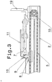
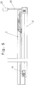
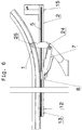
- the sliding door is decoupled from the driver angle 8 via a cable pull and a movable driver pin 9 and thus the connection and power flow to the driver angle is interrupted, the door can now be moved manually in the usual way.
- the decoupling of the driver element can also be done via a lever.
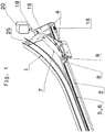
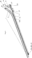
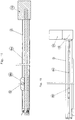
- the guide unit is formed by a straight guide rail 2,3, the deflection of the inserted chain or belt takes place within this guide rail.
- the belt is held together by a cam angle 8, i. There are no endless chains or belts are used, which in turn simplifies installation.
- the Mitauerwinkel 8 is positively guided in the guide rail 2,3, thus occurring in operation transverse forces that occur during the door opening or door closure of the chain 5 or belt 6 kept away.
- a spindle 6a instead of the chain 5 or belt 6 can be used very advantageously also a spindle 6a.
- a spindle nut On the spindle, a spindle nut is installed, the spindle nut is set by the enclosure in the guide rail during rotation of the spindle in translational motion.
- the driving angle 8 is firmly connected to the spindle nut, or the pin is inserted directly into the spindle nut.
- the tension mechanism 7 pulls at a door opening on the door bracket 4, thus the sliding door is opened. In a door closure, the pull mechanism 7 presses against the door holder 4, the door is closed.
- the guide rails 2,3 are screwed flat in the vehicle via a screw and less sheet metal processing with the vehicle floor.
- the screws are easily accessible even during later maintenance or repairs and can be installed and removed very quickly.
- the gear / drive 16 is mounted vertically and coplanar with the guide rail 2.3.
- the available space, like him is used in each vehicle with design of the guide profile 1.
- the motor can be bolted directly to the drive housing or transmission, i. the axis of the motor is in this case perpendicular to the spindle or Frittunsschiene. Accordingly, the engine can be accommodated to save space. In addition, in this arrangement, enough space for the mounted in the guide door bracket or the coupled to the door bracket driver element is left.
- the drive motor is guided out of this area via a flexible shaft 19 and is e.g. above, protected inside the vehicle, can be mounted against rotation.
- advantageous positions of the motor 20 e.g. within the clearances on the motor vehicle pillar, or under plastic panels of the motor vehicle pillars.
- the advantageous use of a flexible shaft allows position-independent positioning of the motor 20 relative to the transmission 16, to which the solution is not critical with respect to mounting tolerances of the motor 20, since the flexible shaft is also an excellent element for tolerance compensation. Any openings on the body for passage in cavities on the motor vehicle pillar only need small diameters wide, which do not affect the strength of the vehicle structure, especially in retrofits.
- the guide unit as well as the complete actuating device can also be advantageously integrated as a completely pre-assembled unit in the vehicle, this has the advantage that vehicle tolerances bridged or compensated in the tolerance chain.
- the design shows with spindle, spindle nut and guide unit with flanged motor on the drive unit, this unit can be used as a whole, in one piece in the space, mounting space.
- an overload clutch 21 to keep out damage, external influences from the transmission.
- a reaction force is generated against the direction of movement of the door.
- brake shoes which is like a car disc brake in detection of emergencies such. via safety edges, close and stop the door abruptly in your motion or inertia.
- a position for the brake shoes this case offers a pinion within the guide rail 2,3.
- the tension mechanism 7 When disengaged drive pin 9, ie operation manual door adjustment, the tension mechanism 7 by means of a spring 24, preferably a leg spring against the Guide rail pressed. And defined in the rotational position. This ensures that when passing over, ie manual movement of the door, and when not actuated door handle, the system again finds positive fit, ie the driving pin 9 engages in the driving angle 8 against the compression spring 10 on the driving pin 9. Thus, the door can be electrically operated again.
- the solution to this problem is a rail-guided traction mechanism 7 which is arranged on the lower guide 1 of the sliding door and can be driven with the following train pressure means: a toothed belt 6 or a chain 5, or a spindle 6a and 6b spindle nut.
- the arranged on the traction means driving angle 8 is connected via a, arranged on the tension mechanism 7 and by a cable 11, disengageable driving pin 9 with the adjustable door bracket 4.
- the Mitauerwinkel 8 is positively guided in the guide rail 2.3.
- the Mitauerwinkel can also be designed as a spindle nut 6b, at the drive element spindle 6a.
- This mechanism 7 can be unlocked via the built-in drive pin 9 and arranged on the door pull mechanism 7 with the door, so that in case of power failure, emergency, etc., the door can be opened manually. It is also conceivable that a driver opening, such as in Switzerlandmechanikhebel, is provided, in which for the coupling part of the door holder or the drive element (eg, chain, spindle, belt or the like) engages articulated. A mixed operation is optionally also possible by the user.
- the arranged at the ends of the guide rails 2 or 3 timing pulleys 14 or sprockets 13 deflect the timing belt 6 or chain 5 to.
- a toothed belt pulley or sprocket is driven via a gear 16, so that in the rail arranged traction device is adjusted linearly.
- Particularly advantageous is the design as a drive element spindle 6a and spindle nut 6b, since no deflections are required and the space requirement is very low.
- the spindle 6a and spindle nut 6b can absorb large forces, also is on the slope of the spindle, a change in speed adjustable without changing the space.
- This transmission 16 is driven via an overload mechanism 21 with an electric motor 20 via a flexible shaft 19.
- the electric motor 20 is preferably installed in a protected space against rotation and is connected to the drive gear 16 via a flexible shaft 19.
- inventive task was solved in the form that the clamping device 12 and the voltage within the actuator or guide rail 2.3 are shown.
- the tensioning device 12 can be realized very easily via an eccentric arrangement. Via the rotation of the eccentric, the sprocket 13 or toothed belt wheel 14 is moved in the longitudinal direction and thus the chain 5, or the toothed belt 6 is biased.
- the guide rail can be made in two parts, this two rails are used, a rail rests on the vehicle floor and the second rail rests on the sill plate of the vehicle. Both rails are still within the floor assembly between sill and vehicle floor.
- This design ensures that additional space for the driving pin 9, driving angle 8 and in particular for the tension mechanism 7 is created.
- the arrangement of the listed elements is in this design between or within the two-piece rail.
- This construction also has a further advantage that, due to the two-part design or exploded construction, the oblong hole of the guide rail 3 for the driving lug 9 is located on the side facing the vehicle floor, i. the guide system is further improved because this results in additional protection solely by the rotation of the slot down against the ingress of dirt particles in the rail.
- the drive unit with spindle 6a and spindle nut is proposed, this unit requires no deflections and can be installed in very tight spaces.
- the internal forces are absorbed by the guide rail 2 and introduced via their attachment to the vehicle structure.
Landscapes
- Power-Operated Mechanisms For Wings (AREA)
Applications Claiming Priority (1)
| Application Number | Priority Date | Filing Date | Title |
|---|---|---|---|
| DE102016005161.2A DE102016005161B4 (de) | 2016-04-28 | 2016-04-28 | Betätigungseinrichtung für eine Kraftfahrzeug Schiebetür |
Publications (1)
| Publication Number | Publication Date |
|---|---|
| EP3239448A1 true EP3239448A1 (fr) | 2017-11-01 |
Family
ID=58638774
Family Applications (1)
| Application Number | Title | Priority Date | Filing Date |
|---|---|---|---|
| EP17168441.8A Withdrawn EP3239448A1 (fr) | 2016-04-28 | 2017-04-27 | Dispositif d'actionnement pour une porte coulissante de véhicule automobile |
Country Status (2)
| Country | Link |
|---|---|
| EP (1) | EP3239448A1 (fr) |
| DE (2) | DE102016005161B4 (fr) |
Cited By (3)
| Publication number | Priority date | Publication date | Assignee | Title |
|---|---|---|---|---|
| CN108825044A (zh) * | 2018-06-17 | 2018-11-16 | 桂林京达科技有限公司 | 一种具有倍速链的外滑移门系统 |
| CN111059245A (zh) * | 2019-12-31 | 2020-04-24 | 天津莫德曼机器人有限公司 | 一种同步带密封模组 |
| EP3538730B1 (fr) * | 2016-11-11 | 2020-12-30 | Gebr. Bode GmbH & Co. KG | Dispositif d'entraînement pour un élément à entraîner |
Citations (4)
| Publication number | Priority date | Publication date | Assignee | Title |
|---|---|---|---|---|
| GB421433A (en) * | 1934-03-27 | 1934-12-20 | Fritz Kiekert | Improvements in or relating to opening and closing devices for sliding doors and the like |
| US5063710A (en) * | 1990-09-24 | 1991-11-12 | Itt Corporation | Power drive for sliding door |
| WO1993017211A1 (fr) * | 1992-02-28 | 1993-09-02 | Ruchat Rene | Dispositif commandant l'ouverture et la fermeture d'une porte coulissant horizontalement dans un vehicule |
| DE4341153A1 (de) | 1993-12-02 | 1995-06-08 | Johann Engelschall | Schiebetür-Antriebsvorrichtung und -steuerung |
Family Cites Families (4)
| Publication number | Priority date | Publication date | Assignee | Title |
|---|---|---|---|---|
| DE19702698C2 (de) | 1996-04-02 | 1999-03-18 | Kiekert Ag | Kraftfahrzeug mit zumindest einer in einer Seitenwand angeordneten Schiebetür |
| DE19632427C2 (de) | 1996-08-12 | 2002-02-21 | Webasto Tuersysteme Gmbh | Schwenkschiebetür für Fahrzeuge |
| DE19819421C2 (de) | 1998-04-30 | 2001-11-08 | Kiekert Ag | Schiebetürantrieb für die Schiebetür eines Kraftfahrzeuges |
| DE202005014450U1 (de) | 2005-09-12 | 2007-02-01 | BROSE SCHLIEßSYSTEME GMBH & CO. KG | Schiebetüranordnung für ein Kraftfahrzeug |
-
2016
- 2016-04-28 DE DE102016005161.2A patent/DE102016005161B4/de active Active
-
2017
- 2017-04-27 EP EP17168441.8A patent/EP3239448A1/fr not_active Withdrawn
- 2017-04-27 DE DE202017007006.5U patent/DE202017007006U1/de not_active Expired - Lifetime
Patent Citations (4)
| Publication number | Priority date | Publication date | Assignee | Title |
|---|---|---|---|---|
| GB421433A (en) * | 1934-03-27 | 1934-12-20 | Fritz Kiekert | Improvements in or relating to opening and closing devices for sliding doors and the like |
| US5063710A (en) * | 1990-09-24 | 1991-11-12 | Itt Corporation | Power drive for sliding door |
| WO1993017211A1 (fr) * | 1992-02-28 | 1993-09-02 | Ruchat Rene | Dispositif commandant l'ouverture et la fermeture d'une porte coulissant horizontalement dans un vehicule |
| DE4341153A1 (de) | 1993-12-02 | 1995-06-08 | Johann Engelschall | Schiebetür-Antriebsvorrichtung und -steuerung |
Cited By (4)
| Publication number | Priority date | Publication date | Assignee | Title |
|---|---|---|---|---|
| EP3538730B1 (fr) * | 2016-11-11 | 2020-12-30 | Gebr. Bode GmbH & Co. KG | Dispositif d'entraînement pour un élément à entraîner |
| CN108825044A (zh) * | 2018-06-17 | 2018-11-16 | 桂林京达科技有限公司 | 一种具有倍速链的外滑移门系统 |
| CN108825044B (zh) * | 2018-06-17 | 2023-10-17 | 桂林京达科技有限公司 | 一种具有倍速链的外滑移门系统 |
| CN111059245A (zh) * | 2019-12-31 | 2020-04-24 | 天津莫德曼机器人有限公司 | 一种同步带密封模组 |
Also Published As
| Publication number | Publication date |
|---|---|
| DE102016005161A1 (de) | 2017-11-02 |
| DE102016005161B4 (de) | 2025-07-31 |
| DE202017007006U1 (de) | 2019-02-25 |
Similar Documents
| Publication | Publication Date | Title |
|---|---|---|
| EP1778942B1 (fr) | Systeme de deplacement pour porte de vehicule automobile | |
| WO2019076398A1 (fr) | Dispositif d'installation pour une portière de véhicule automobile | |
| DE202010000524U1 (de) | Schiebetritt mit zusätzlichem Klapptritt | |
| DE102013113483B4 (de) | Schiebetüreinrichtung für die seitliche Türöffnung eines Personenkraftfahrzeugs; Personenkraftfahrzeug mit Schiebetüreinrichtung | |
| DE19737996C2 (de) | Schließkeil-Antriebsbaugruppe für ein Kraftfahrzeug-Türschloß o. dgl. | |
| DE102009018188B4 (de) | Vorrichtung zum automatischen Schließen einer Fahrzeugtür | |
| DE4401413A1 (de) | Fahrzeugtür | |
| DE202017007006U1 (de) | Betätigungseinrichtung für eine Kraftfahrzeug Schiebetür | |
| EP2821572A2 (fr) | Unité de fermeture assistée pour une porte de véhicule automobile | |
| DE102008024341A1 (de) | Türbetätigungsvorrichtung mit einer Notöffnungseinrichtung | |
| DE19853989C1 (de) | Vorrichtung zum Öffnen und Verschliessen einer Öffnung in einer Wandung mittels einer Schiebetür | |
| EP1002923A2 (fr) | Dispositif d'ouverture et de fermeture d'une ouverture dans une paroi au moyen d'une porte coulissante | |
| DE202019105449U1 (de) | Zuziehhilfe für eine Fahrzeugtür/Fahrzeugklappe | |
| EP1840312A2 (fr) | Porte coulissante | |
| DE3737385C2 (de) | Vorrichtung zum Öffnen und Schließen eines Tores | |
| EP3656961B1 (fr) | Agencement de porte | |
| DE202005007984U1 (de) | Schiebetür oder Schwenkschiebetür für Fahrzeuge des öffentlichen Personennah- und -fernverkehrs | |
| DE102007030139B4 (de) | Verstellantrieb zur Bewegung eines Funktionselementes in oder an einer Kraftfahrzeugkarosserie | |
| DE10343359A1 (de) | Ver- und Entriegelungsvorrichtung für zweiflügelige Fahrzeugtüren, insbesondere Schwenkschiebetüren für Schienenfahrzeuge | |
| DE102006036412A1 (de) | Vorrichtung zum Bewegen einer Schiebetür mit einer Notbetätigung | |
| DE102016003155A1 (de) | Kraftfahrzeug mit automatischem Karosserieklappenantrieb | |
| EP4204653A1 (fr) | Dispositif d'entrouverture pour un élément de porte de véhicule à moteur | |
| DE102013202801A1 (de) | Einrichtung zur motorischen Betätigung einer Kraftfahrzeug-Türe mit Feststellfunktion | |
| DE10332045A1 (de) | Kraftfahrzeug | |
| EP1724138A2 (fr) | Porte coulissante ou pivotante-coulissante pour véhicules de transport urbain et à grande distance de personnes |
Legal Events
| Date | Code | Title | Description |
|---|---|---|---|
| PUAI | Public reference made under article 153(3) epc to a published international application that has entered the european phase |
Free format text: ORIGINAL CODE: 0009012 |
|
| STAA | Information on the status of an ep patent application or granted ep patent |
Free format text: STATUS: THE APPLICATION HAS BEEN PUBLISHED |
|
| AK | Designated contracting states |
Kind code of ref document: A1 Designated state(s): AL AT BE BG CH CY CZ DE DK EE ES FI FR GB GR HR HU IE IS IT LI LT LU LV MC MK MT NL NO PL PT RO RS SE SI SK SM TR |
|
| AX | Request for extension of the european patent |
Extension state: BA ME |
|
| STAA | Information on the status of an ep patent application or granted ep patent |
Free format text: STATUS: REQUEST FOR EXAMINATION WAS MADE |
|
| 17P | Request for examination filed |
Effective date: 20180430 |
|
| RBV | Designated contracting states (corrected) |
Designated state(s): AL AT BE BG CH CY CZ DE DK EE ES FI FR GB GR HR HU IE IS IT LI LT LU LV MC MK MT NL NO PL PT RO RS SE SI SK SM TR |
|
| STAA | Information on the status of an ep patent application or granted ep patent |
Free format text: STATUS: EXAMINATION IS IN PROGRESS |
|
| 17Q | First examination report despatched |
Effective date: 20181017 |
|
| STAA | Information on the status of an ep patent application or granted ep patent |
Free format text: STATUS: THE APPLICATION HAS BEEN WITHDRAWN |
|
| 18W | Application withdrawn |
Effective date: 20190226 |