EP3239451A1 - Dispositif de controle d'acces pour personnes sous forme de verrou rotatif ou dispositif de comptage de personnes - Google Patents
Dispositif de controle d'acces pour personnes sous forme de verrou rotatif ou dispositif de comptage de personnes Download PDFInfo
- Publication number
- EP3239451A1 EP3239451A1 EP16167003.9A EP16167003A EP3239451A1 EP 3239451 A1 EP3239451 A1 EP 3239451A1 EP 16167003 A EP16167003 A EP 16167003A EP 3239451 A1 EP3239451 A1 EP 3239451A1
- Authority
- EP
- European Patent Office
- Prior art keywords
- turnstile
- shaft
- passage
- access control
- running
- Prior art date
- Legal status (The legal status is an assumption and is not a legal conclusion. Google has not performed a legal analysis and makes no representation as to the accuracy of the status listed.)
- Granted
Links
- 230000004888 barrier function Effects 0.000 claims description 32
- 238000013475 authorization Methods 0.000 claims description 15
- 230000000903 blocking effect Effects 0.000 claims description 15
- 238000000926 separation method Methods 0.000 claims description 9
- 230000005540 biological transmission Effects 0.000 claims description 6
- 238000001514 detection method Methods 0.000 claims description 6
- 238000011144 upstream manufacturing Methods 0.000 claims description 2
- 230000000694 effects Effects 0.000 description 2
- 230000001771 impaired effect Effects 0.000 description 2
- 208000027418 Wounds and injury Diseases 0.000 description 1
- 230000004913 activation Effects 0.000 description 1
- 238000001994 activation Methods 0.000 description 1
- 230000006378 damage Effects 0.000 description 1
- 230000001419 dependent effect Effects 0.000 description 1
- 208000014674 injury Diseases 0.000 description 1
- 238000010200 validation analysis Methods 0.000 description 1
Images



Classifications
-
- E—FIXED CONSTRUCTIONS
- E06—DOORS, WINDOWS, SHUTTERS, OR ROLLER BLINDS IN GENERAL; LADDERS
- E06B—FIXED OR MOVABLE CLOSURES FOR OPENINGS IN BUILDINGS, VEHICLES, FENCES OR LIKE ENCLOSURES IN GENERAL, e.g. DOORS, WINDOWS, BLINDS, GATES
- E06B11/00—Means for allowing passage through fences, barriers or the like, e.g. stiles
- E06B11/08—Turnstiles; Gates for control of entry or exit of persons, e.g. in supermarkets
-
- E—FIXED CONSTRUCTIONS
- E05—LOCKS; KEYS; WINDOW OR DOOR FITTINGS; SAFES
- E05F—DEVICES FOR MOVING WINGS INTO OPEN OR CLOSED POSITION; CHECKS FOR WINGS; WING FITTINGS NOT OTHERWISE PROVIDED FOR, CONCERNED WITH THE FUNCTIONING OF THE WING
- E05F15/00—Power-operated mechanisms for wings
- E05F15/60—Power-operated mechanisms for wings using electrical actuators
-
- E—FIXED CONSTRUCTIONS
- E05—LOCKS; KEYS; WINDOW OR DOOR FITTINGS; SAFES
- E05Y—INDEXING SCHEME ASSOCIATED WITH SUBCLASSES E05D AND E05F, RELATING TO CONSTRUCTION ELEMENTS, ELECTRIC CONTROL, POWER SUPPLY, POWER SIGNAL OR TRANSMISSION, USER INTERFACES, MOUNTING OR COUPLING, DETAILS, ACCESSORIES, AUXILIARY OPERATIONS NOT OTHERWISE PROVIDED FOR, APPLICATION THEREOF
- E05Y2900/00—Application of doors, windows, wings or fittings thereof
- E05Y2900/40—Application of doors, windows, wings or fittings thereof for gates
Definitions
- the present invention relates to an access control device designed as a turnstile for persons or as a turnstile device for counting persons according to the preamble of patent claim 1.
- Access control devices for persons and devices for counting people are known from the prior art as turnstiles. They comprise one, two or three locking arms, which are rotatably connected to a shaft driven by an electric motor, wherein the angles between the longitudinal axes of the locking arms are predetermined by the rotationally fixed connection.
- turnstile with three locking arms is due to the fixed angle between the locking arms of the comfort of passing through impaired, for example, because luggage or strollers must be lifted over one of the three locking arms.
- the angle between the longitudinal axes of two adjacent locking arms is 120 °, moreover, not the entire passage can be released because a locking arm always protrudes into the passage.
- Turnstiles with three locking arms have the advantage that they have sufficient locks and Ensuring a separation effect, as a person is always passing between two barrier arms while passing.
- turnstiles are known with two locking arms, which are rotatably connected to a shaft driven by an electric motor, but which can not eliminate the aforementioned disadvantages of the turnstile, comprising three locking arms. Rather, a safe separation is impaired.
- turnstiles are known with a locking arm, which, however, to ensure a separation, moved very quickly, on the one hand to release the passage and on the other hand to ensure separation, thereby increasing the risk of injury to through people.
- the wear is increased disadvantageously due to the high rotational speed of the mass of a locking arm; the high speed of rotation is due to the fact that one blocking arm has to be rotated by 360 degrees per pass.
- the present invention has for its object to provide an executed as a turnstile access control device for persons or as a turnstile running device for counting people, which ensures a good separation while releasing the entire passage in the case of a valid access authorization.
- an access control device designed as a turnstile for people or as a turnstile device for counting people
- a housing in which at least one drive means is arranged, which has two of the at least one drive means drivable locking arms, which independently and with the same or different speed can be driven and controlled.
- the locking arms are driven independently of each other and controlled so that a secure separation and a valid access authorization a release of the entire passage can be achieved.
- the two locking arms are preferably independently drivable and controllable such that in the presence of a valid access authorization in the case of an access control device or detection of a person in the passage in the case of a device for people counting the arranged in the passage direction in a starting position in front of a person barrier arm, which blocks the passage, completely clears the passage in front of the person, wherein the second blocking arm, which releases the passage in the starting position, is activated in such a way that it blocks the passage in the direction of passage behind the person and the starting position is assumed again, wherein successive Starting positions the position of the locking arms is reversed.
- access authorizations in the prior art are detected by a reader of the access control device, the validation being done either locally or in a server connected to the access control device.
- the reading device can be, for example, an RFID reading device, a fingerprint scanner, an iris scanner, a barcode reader or a magnetic card reader.
- the reading device can be a reading device which can read access authorizations or IDs assigned to a valid access authorization from a customer medium by means of Bluetooth, Bluetooth Low Energy, WLAN or UWB standards.
- the turnstile may have multiple readers for different standards.
- a first locking arm on a first shaft and a second locking arm are arranged on a second shaft, wherein the first shaft is designed as a hollow shaft through which the second shaft is guided.
- the first and second shafts are arranged coaxially with each other.
- the locking arms are rotatably connected to the respective shaft at a predetermined angle to the shaft; For example, the locking arms are plugged or screwed on the respective shaft.
- each shaft is associated with a drive means, which may for example be designed as an electric motor which drives the shaft.
- the waves can be hydraulically, pneumatically or electromagnetically driven.
- the drive means is an electric motor with a power flow direction upstream of the electric motor gear, wherein the respective shaft is driven by an output of the transmission.
- the transmission can be embodied, for example, as a planetary gear, as a spur gear or as a belt transmission or as a combination of the aforementioned types of transmission.
- only one drive means e.g. an electric motor can be provided, which is preceded by a gear with two outputs, wherein an output is connected to a shaft or releasably connectable by means of a controllable clutch, wherein when the clutch is open, the waves are rotatable against a predetermined resistance, which is selected such that the respective locking arm is held without external force and can be rotated with a defined torque.
- the transmissions are designed in such a way that a desired control of the locking arms connected to the shafts, in particular a control, is made possible, which enables secure separation and, with a valid access authorization, a release of the entire passage.
- the first shaft designed as a hollow shaft has at its end remote from the housing of the turnstile a recess from which protrudes the second locking arm associated with the second shaft, wherein the recess extends over a predetermined angular range, for example, values between 200 ° and 300 ° can assume and wherein the first and second locking arm axially projecting along the central longitudinal axes of the coaxially arranged waves viewed from the same axial position.
- the recess is arranged diametrically opposite to the first shaft connected to the first locking arm. That way, both can to each other by an angular range, which corresponds substantially to the angular range of the recess of the hollow shaft, independently movable.
- rotatably connected to the second shaft second locking arm protrudes from the housing of the turnstile facing away from the end of the designed as a hollow shaft shaft first, so that any relative movement of the two locking arms to each other can be achieved.
- both locking arms each rotate along different trajectories.
- both locking arms are controlled so that they extend in the smallest possible angle to each other in the direction of the plane of the passage, so that the passage is released.
- the smallest possible angle between the locking arms is approximately 360 ° minus the angular range of the recess , Accordingly, for example, the smallest possible angle between the locking arms 80 ° for the case that the recess extends over an angular range of 280 °.
- the locking arms are driven so that they are arranged substantially parallel to each other.
- the turnstile on a battery which supplies in a power failure, preferably designed as electric motors drive means with power, which ensures that in an emergency, or when the turnstile is to be switched permanently out of service, both locking arms so controlled are that they extend in the smallest possible angle towards each other in the direction of the plane of the passage, so that the passage is released.
- a turnstile which the functionality of a conventional turnstile with three locking arms in terms of lock and separating effect without, however, resulting from the presence of the three locking arms disadvantages in terms of Has comfort. It also ensures that the entire passage is released in an emergency.
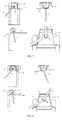
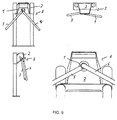
- a turnstile is denoted by 1, wherein a housing of the turnstile 1 with 2, a first barrier arm with 3 and a second barrier arm with 4 are designated. Further, 5 denotes the drivable shaft, with which the first locking arm 3 is rotatably connected, wherein 6 denotes the drivable shaft, with which the second locking arm 3 is rotatably connected.
- a turnstile 1 according to the invention, comprises a housing 2 in which drive means are arranged. Furthermore, the turnstile 1 comprises two drivable by the drive means locking arms 3, 4, which are independently and at the same or different speed driven and controlled, such that a secure separation and valid access authorization, a release of the entire passage can be achieved.
- a first locking arm 3 are arranged on a first shaft 5 and a second locking arm 4 on a second shaft 6, wherein the first shaft 5 is designed as a hollow shaft through which the second shaft 6 is guided, wherein the first and second shaft 5, 6 are arranged coaxially with each other and wherein the locking arms 3, 4th with the respective shaft 5, 6 are rotatably connected at a predetermined angle to the shaft.
- Each shaft 5, 6 is associated with a controllable by a control drive means which drives the shaft 5, 6.
- the shafts 5, 6 are each driven by an electric motor.
- the first shaft 5 designed as a hollow shaft has at its end facing away from the housing 2 of the turnstile 1 a recess which is arranged diametrically opposite the first blocking arm 3 connected to the first shaft 5, from which the second blocking arm assigned to the second shaft 6 4 stands out.
- the recess extends over 240 °;
- the first and second locking arms protrude axially along the central longitudinal axes of the coaxial shafts 5, 6 as viewed from the same axial position.
- the passage is blocked by the second locking arm 4, wherein the first locking arm 3 releases the passage and slightly protrudes into the passage to complicate an underclimbing, whereby a person can comfortably approach the second barrier arm 4 and wherein the angle between the first and the second barrier arm is about 120 °.
- the first locking arm 3 in the initial position of the lock arm, which does not block the passage, ie in the in FIG. 1 shown example, the first locking arm 3, the passage completely release; the corresponding position of the lock arm corresponds for example to the position of the first lock arm 3 in FIG FIG. 6 ,
- the second lock arm 4 When a person who stands in front of the passage blocking the second lock arm 4 and carries a valid access authorization, which is detected by a reading device, not shown, the second lock arm 4 is driven so that it is rotated by 30 ° in the through direction, such as based FIG. 2 illustrated. By further rotation through another 90 °, the entire passage is released to allow the person the passage, as shown FIG. 3 shown.
- the first locking arm 3 is not rotated during the rotation of the second locking arm 4.
- the first blocking arm can be turned by a small angle, for example by 30 °, in order to start at this point in time to block the passage behind the person.
- first and second barrier arms 3, 4 are rotated independently of each other, at the end of these rotational movements, the second barrier arm 4 extends substantially perpendicular to the plane of the passage and the first barrier arm 3 begins the passage behind the person who has gone through, to block; this situation is based on FIG. 4 illustrated.
- the locking arms 3, 4 are rotated independently of each other so that the starting position after FIG. 1 is achieved, with the difference that the first locking arm 3 blocks the passage, the second locking arm 4 releases the entire passage.
- the locking arms 3, 4 are driven so that they extend at the smallest possible angle to each other down in the direction of the plane of the passage, so that the passage is released.
- the smallest possible angle between the locking arms due to the designed as a hollow shaft first shaft 5 120 ° as the recess of the hollow shaft 5 extends over an angular range of 240 °.
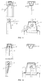
- the passage is blocked by the second locking arm 4, wherein the first locking arm 3 protrudes slightly into the passage to complicate a Unterklettern.
- the first blocking arm 3 in the initial position of the lock arm, which does not block the passage, ie in the in FIG. 7 shown example, the first blocking arm 3, the passage completely release.
- the second barrier arm 4 is driven such that it by 30 ° in the direction of passage is rotated as shown FIG. 8 illustrated. By further rotation through another 90 °, the entire passage is released to the person's passage to grant, as by FIG. 9 shown.
- the first locking arm 3 is not rotated during the rotation of the second locking arm 4.
- the first blocking arm can be turned by a small angle, for example by 30 °, in order to start at this point in time to block the passage behind the person.
- first and second barrier arms 3, 4 are rotated independently of each other, at the end of these rotational movements, the second barrier arm 4 extends substantially perpendicular to the plane of the passage and the first barrier arm 3 begins the passage behind the person who has gone through, to block; this situation is based on FIG. 10 illustrated.
- the locking arms 3, 4 are rotated independently of each other so that the starting position after FIG. 7 is achieved, with the difference that the first locking arm 3 blocks the passage, the second locking arm 4 releases the entire passage.
- the locking arms 3, 4 are driven so that they extend at the smallest possible angle to each other down in the direction of the plane of the passage, so that the passage is released.
- the smallest possible angle is 0 °, since any relative movement of the two locking arms 3, 4 to each other can be achieved.
- the locking arms 3, 4 extend with their longitudinal axes substantially parallel to each other down in the direction of the plane of the passage, so that the passage is released.
Landscapes
- Engineering & Computer Science (AREA)
- Civil Engineering (AREA)
- Structural Engineering (AREA)
- Devices For Checking Fares Or Tickets At Control Points (AREA)
- Lock And Its Accessories (AREA)
- Power-Operated Mechanisms For Wings (AREA)
Priority Applications (5)
| Application Number | Priority Date | Filing Date | Title |
|---|---|---|---|
| ES16167003.9T ES2669732T3 (es) | 2016-04-26 | 2016-04-26 | Dispositivo de control de acceso diseñado como torniquete para las personas o como dispositivo para el recuento de las personas |
| EP16167003.9A EP3239451B1 (fr) | 2016-04-26 | 2016-04-26 | Dispositif de controle d'acces pour personnes sous forme de verrou rotatif ou dispositif de comptage de personnes |
| AU2017202227A AU2017202227B2 (en) | 2016-04-26 | 2017-04-04 | Access control device for persons or device for counting persons designed as a turnstile |
| US15/486,687 US10006247B2 (en) | 2016-04-26 | 2017-04-13 | Access control device for persons or device for counting persons designed as a turnstile |
| CA2965108A CA2965108C (fr) | 2016-04-26 | 2017-04-24 | Dispositif de controle d'acces destine aux personnes ou compteur de personnes designees dans un tourniquet |
Applications Claiming Priority (1)
| Application Number | Priority Date | Filing Date | Title |
|---|---|---|---|
| EP16167003.9A EP3239451B1 (fr) | 2016-04-26 | 2016-04-26 | Dispositif de controle d'acces pour personnes sous forme de verrou rotatif ou dispositif de comptage de personnes |
Publications (2)
| Publication Number | Publication Date |
|---|---|
| EP3239451A1 true EP3239451A1 (fr) | 2017-11-01 |
| EP3239451B1 EP3239451B1 (fr) | 2018-03-14 |
Family
ID=55910758
Family Applications (1)
| Application Number | Title | Priority Date | Filing Date |
|---|---|---|---|
| EP16167003.9A Not-in-force EP3239451B1 (fr) | 2016-04-26 | 2016-04-26 | Dispositif de controle d'acces pour personnes sous forme de verrou rotatif ou dispositif de comptage de personnes |
Country Status (5)
| Country | Link |
|---|---|
| US (1) | US10006247B2 (fr) |
| EP (1) | EP3239451B1 (fr) |
| AU (1) | AU2017202227B2 (fr) |
| CA (1) | CA2965108C (fr) |
| ES (1) | ES2669732T3 (fr) |
Cited By (1)
| Publication number | Priority date | Publication date | Assignee | Title |
|---|---|---|---|---|
| WO2023131382A1 (fr) * | 2022-01-07 | 2023-07-13 | ELKA Torantriebe GmbH u. Co. Betriebs KG | Dispositif d'individualisation du passage de personnes dans une zone d'individualisation de passage ainsi que dispositif d'individualisation du passage de personnes |
Families Citing this family (6)
| Publication number | Priority date | Publication date | Assignee | Title |
|---|---|---|---|---|
| RU182382U1 (ru) * | 2017-12-27 | 2018-08-15 | Общество с ограниченной ответственностью Научно-производственное объединение "Сибирский Арсенал" | Механизм турникета-трипода |
| DE102020002894B4 (de) * | 2020-05-14 | 2022-07-07 | Martin Eberlein | Durchgangsanlage |
| TWI835285B (zh) * | 2022-09-07 | 2024-03-11 | 富世達股份有限公司 | 通關機的轉動裝置 |
| USD1072279S1 (en) * | 2023-01-26 | 2025-04-22 | ELKA Torantriebe GmbH u. Co. Betriebs KG | Access control device |
| EP4571038A1 (fr) | 2023-12-14 | 2025-06-18 | By Techdesign S.L. | Passage automatique avancé pour controler l'accès d'un piéton |
| CN120819259B (zh) * | 2025-08-15 | 2026-04-14 | 苏州园科生态建设集团有限公司 | 一种具有保护作用的园林观景眺望平台 |
Citations (2)
| Publication number | Priority date | Publication date | Assignee | Title |
|---|---|---|---|---|
| US1215906A (en) * | 1915-12-01 | 1917-02-13 | Robert M Campbell | Automatically-controlled gate. |
| DE102005028712A1 (de) * | 2005-06-20 | 2006-12-21 | Gallenschütz, Thomas | Personenschleuse |
Family Cites Families (18)
| Publication number | Priority date | Publication date | Assignee | Title |
|---|---|---|---|---|
| US1617918A (en) * | 1925-03-06 | 1927-02-15 | Francis J Mcloughlin | Turnstile |
| US3998008A (en) * | 1975-04-30 | 1976-12-21 | Qonaar Corporation | Turnstile head mechanism construction |
| US5056261A (en) * | 1990-12-19 | 1991-10-15 | Cubic Automatic Revenue Collection Group | Turnstile system |
| AT405338B (de) * | 1995-11-16 | 1999-07-26 | Skidata Gmbh | Drehsperre |
| AT407096B (de) * | 1998-05-25 | 2000-12-27 | Karl Gotschlich Maschinenbau G | Drehsperre |
| SE514224C2 (sv) * | 1999-05-28 | 2001-01-22 | Gunnebo Entrance Control Ab | Vändkors för entréspärrar |
| DE102004013965B3 (de) * | 2004-03-19 | 2005-12-01 | Skidata Ag | Zutrittskontrollvorrichtung |
| EP1609942B1 (fr) * | 2004-06-21 | 2006-11-29 | SkiData AG | Tourniquet |
| DE102005010714A1 (de) * | 2005-03-09 | 2006-09-14 | Skidata Ag | Drehsperre |
| DE202005012659U1 (de) * | 2005-08-11 | 2005-10-20 | Magnetic Autocontrol Gmbh | Drehsperre |
| DE102006026221A1 (de) * | 2006-06-06 | 2007-12-13 | Skidata Ag | Drehsperre |
| US7845115B2 (en) * | 2006-08-31 | 2010-12-07 | Skidata Ag | Access control apparatus |
| DE102007036360A1 (de) * | 2007-07-31 | 2009-02-05 | Gallenschütz, Thomas | Personenschleuse |
| EP2717235B1 (fr) * | 2012-10-04 | 2015-01-07 | Skidata Ag | Dispositif de contrôle d'accès pour personnes sous forme de verrou rotatif |
| EP2719855B1 (fr) * | 2012-10-12 | 2015-07-22 | Locinox | Ensemble de commande pour commander la rotation d'un tourniquet |
| US9243449B1 (en) * | 2014-07-09 | 2016-01-26 | Z Image, Llc | Automated entrance |
| US9784032B2 (en) * | 2014-08-27 | 2017-10-10 | Boon Edam, Inc. | Dual turnstile |
| EP2995762A1 (fr) * | 2014-09-15 | 2016-03-16 | Startec S.r.l. | Procédé et système de mouvement de grille automatique |
-
2016
- 2016-04-26 EP EP16167003.9A patent/EP3239451B1/fr not_active Not-in-force
- 2016-04-26 ES ES16167003.9T patent/ES2669732T3/es active Active
-
2017
- 2017-04-04 AU AU2017202227A patent/AU2017202227B2/en not_active Ceased
- 2017-04-13 US US15/486,687 patent/US10006247B2/en not_active Expired - Fee Related
- 2017-04-24 CA CA2965108A patent/CA2965108C/fr not_active Expired - Fee Related
Patent Citations (2)
| Publication number | Priority date | Publication date | Assignee | Title |
|---|---|---|---|---|
| US1215906A (en) * | 1915-12-01 | 1917-02-13 | Robert M Campbell | Automatically-controlled gate. |
| DE102005028712A1 (de) * | 2005-06-20 | 2006-12-21 | Gallenschütz, Thomas | Personenschleuse |
Cited By (2)
| Publication number | Priority date | Publication date | Assignee | Title |
|---|---|---|---|---|
| WO2023131382A1 (fr) * | 2022-01-07 | 2023-07-13 | ELKA Torantriebe GmbH u. Co. Betriebs KG | Dispositif d'individualisation du passage de personnes dans une zone d'individualisation de passage ainsi que dispositif d'individualisation du passage de personnes |
| US12442247B2 (en) | 2022-01-07 | 2025-10-14 | ELKA Torantriebe GmbH u. Co. Betriebs KG | Device for separating persons in a separating region, and person separating device |
Also Published As
| Publication number | Publication date |
|---|---|
| EP3239451B1 (fr) | 2018-03-14 |
| CA2965108C (fr) | 2019-03-26 |
| AU2017202227B2 (en) | 2018-06-28 |
| CA2965108A1 (fr) | 2017-10-26 |
| AU2017202227A1 (en) | 2017-11-09 |
| US20170306698A1 (en) | 2017-10-26 |
| ES2669732T3 (es) | 2018-05-29 |
| US10006247B2 (en) | 2018-06-26 |
Similar Documents
| Publication | Publication Date | Title |
|---|---|---|
| EP3239451B1 (fr) | Dispositif de controle d'acces pour personnes sous forme de verrou rotatif ou dispositif de comptage de personnes | |
| AT500304B1 (de) | Aufbewahrungsautomat für gegenstände | |
| DE2819424C2 (de) | Antriebsvorrichtung für Türen | |
| DE69332230T2 (de) | Hochsicherheits-Verriegelungsmechanismus | |
| EP2964860B1 (fr) | Mécanisme de commande pour une porte de meuble | |
| EP2717235B1 (fr) | Dispositif de contrôle d'accès pour personnes sous forme de verrou rotatif | |
| EP2132475B1 (fr) | Dispositif pour le maintien libérable d'un état fermé de manière verrouillée d'un dispositif de séparation de compartiment | |
| EP3517714B1 (fr) | Gâchette et dispositif de sécurité de faible encombrement | |
| DE3632904A1 (de) | Schliesseinrichtung fuer ein mechanisch/elektronisches schliess-system | |
| DE69604418T2 (de) | Selbstöffnende eingangsvorrichtung für kontrollierte bereiche | |
| EP3366877A1 (fr) | Sas pour personnes | |
| EP3660793B1 (fr) | Dispositif de contrôle d'accès pour personnes ou véhicules | |
| DE10356614B4 (de) | Motorisierter Sitz zum Drehen der Lehne und Verfahren | |
| CH660768A5 (en) | Gate for people | |
| EP3252259B1 (fr) | Dispositif d'entrainement d'un volet roulant et volet roulant | |
| DE102016210779B4 (de) | Türbeschlag mit einer Kupplung | |
| DE102009036870A1 (de) | Türeinheit | |
| EP3113125B1 (fr) | Dispositif de sortie pour un automate de marchandises | |
| EP2681394A2 (fr) | Barrière de passage | |
| DE10002062B4 (de) | Karusselltür | |
| DE202022104146U1 (de) | Personensperre | |
| EP1983525B1 (fr) | Sas électromagnétique pour le passage de personnes | |
| DE202009003938U1 (de) | Durchgangskontrollvorrichtung | |
| DE2901494B2 (de) | Drehtüranordnung | |
| EP4019736A1 (fr) | Dispositif d'engrenage d'un dispositif de passage |
Legal Events
| Date | Code | Title | Description |
|---|---|---|---|
| PUAI | Public reference made under article 153(3) epc to a published international application that has entered the european phase |
Free format text: ORIGINAL CODE: 0009012 |
|
| STAA | Information on the status of an ep patent application or granted ep patent |
Free format text: STATUS: REQUEST FOR EXAMINATION WAS MADE |
|
| 17P | Request for examination filed |
Effective date: 20161118 |
|
| AK | Designated contracting states |
Kind code of ref document: A1 Designated state(s): AL AT BE BG CH CY CZ DE DK EE ES FI FR GB GR HR HU IE IS IT LI LT LU LV MC MK MT NL NO PL PT RO RS SE SI SK SM TR |
|
| AX | Request for extension of the european patent |
Extension state: BA ME |
|
| GRAP | Despatch of communication of intention to grant a patent |
Free format text: ORIGINAL CODE: EPIDOSNIGR1 |
|
| STAA | Information on the status of an ep patent application or granted ep patent |
Free format text: STATUS: GRANT OF PATENT IS INTENDED |
|
| INTG | Intention to grant announced |
Effective date: 20171129 |
|
| GRAS | Grant fee paid |
Free format text: ORIGINAL CODE: EPIDOSNIGR3 |
|
| GRAA | (expected) grant |
Free format text: ORIGINAL CODE: 0009210 |
|
| STAA | Information on the status of an ep patent application or granted ep patent |
Free format text: STATUS: THE PATENT HAS BEEN GRANTED |
|
| AK | Designated contracting states |
Kind code of ref document: B1 Designated state(s): AL AT BE BG CH CY CZ DE DK EE ES FI FR GB GR HR HU IE IS IT LI LT LU LV MC MK MT NL NO PL PT RO RS SE SI SK SM TR |
|
| REG | Reference to a national code |
Ref country code: GB Ref legal event code: FG4D Free format text: NOT ENGLISH |
|
| REG | Reference to a national code |
Ref country code: CH Ref legal event code: EP Ref country code: AT Ref legal event code: REF Ref document number: 979067 Country of ref document: AT Kind code of ref document: T Effective date: 20180315 |
|
| REG | Reference to a national code |
Ref country code: IE Ref legal event code: FG4D Free format text: LANGUAGE OF EP DOCUMENT: GERMAN |
|
| REG | Reference to a national code |
Ref country code: DE Ref legal event code: R096 Ref document number: 502016000690 Country of ref document: DE |
|
| REG | Reference to a national code |
Ref country code: FR Ref legal event code: PLFP Year of fee payment: 3 |
|
| REG | Reference to a national code |
Ref country code: CH Ref legal event code: NV Representative=s name: ABREMA AGENCE BREVET ET MARQUES, GANGUILLET, CH |
|
| REG | Reference to a national code |
Ref country code: ES Ref legal event code: FG2A Ref document number: 2669732 Country of ref document: ES Kind code of ref document: T3 Effective date: 20180529 |
|
| REG | Reference to a national code |
Ref country code: NL Ref legal event code: MP Effective date: 20180314 |
|
| REG | Reference to a national code |
Ref country code: LT Ref legal event code: MG4D |
|
| PG25 | Lapsed in a contracting state [announced via postgrant information from national office to epo] |
Ref country code: HR Free format text: LAPSE BECAUSE OF FAILURE TO SUBMIT A TRANSLATION OF THE DESCRIPTION OR TO PAY THE FEE WITHIN THE PRESCRIBED TIME-LIMIT Effective date: 20180314 Ref country code: NO Free format text: LAPSE BECAUSE OF FAILURE TO SUBMIT A TRANSLATION OF THE DESCRIPTION OR TO PAY THE FEE WITHIN THE PRESCRIBED TIME-LIMIT Effective date: 20180614 Ref country code: LT Free format text: LAPSE BECAUSE OF FAILURE TO SUBMIT A TRANSLATION OF THE DESCRIPTION OR TO PAY THE FEE WITHIN THE PRESCRIBED TIME-LIMIT Effective date: 20180314 Ref country code: FI Free format text: LAPSE BECAUSE OF FAILURE TO SUBMIT A TRANSLATION OF THE DESCRIPTION OR TO PAY THE FEE WITHIN THE PRESCRIBED TIME-LIMIT Effective date: 20180314 Ref country code: CY Free format text: LAPSE BECAUSE OF FAILURE TO SUBMIT A TRANSLATION OF THE DESCRIPTION OR TO PAY THE FEE WITHIN THE PRESCRIBED TIME-LIMIT Effective date: 20180314 |
|
| PG25 | Lapsed in a contracting state [announced via postgrant information from national office to epo] |
Ref country code: SE Free format text: LAPSE BECAUSE OF FAILURE TO SUBMIT A TRANSLATION OF THE DESCRIPTION OR TO PAY THE FEE WITHIN THE PRESCRIBED TIME-LIMIT Effective date: 20180314 Ref country code: LV Free format text: LAPSE BECAUSE OF FAILURE TO SUBMIT A TRANSLATION OF THE DESCRIPTION OR TO PAY THE FEE WITHIN THE PRESCRIBED TIME-LIMIT Effective date: 20180314 Ref country code: GR Free format text: LAPSE BECAUSE OF FAILURE TO SUBMIT A TRANSLATION OF THE DESCRIPTION OR TO PAY THE FEE WITHIN THE PRESCRIBED TIME-LIMIT Effective date: 20180615 Ref country code: RS Free format text: LAPSE BECAUSE OF FAILURE TO SUBMIT A TRANSLATION OF THE DESCRIPTION OR TO PAY THE FEE WITHIN THE PRESCRIBED TIME-LIMIT Effective date: 20180314 Ref country code: BG Free format text: LAPSE BECAUSE OF FAILURE TO SUBMIT A TRANSLATION OF THE DESCRIPTION OR TO PAY THE FEE WITHIN THE PRESCRIBED TIME-LIMIT Effective date: 20180614 |
|
| PG25 | Lapsed in a contracting state [announced via postgrant information from national office to epo] |
Ref country code: MT Free format text: LAPSE BECAUSE OF FAILURE TO SUBMIT A TRANSLATION OF THE DESCRIPTION OR TO PAY THE FEE WITHIN THE PRESCRIBED TIME-LIMIT Effective date: 20180314 |
|
| PG25 | Lapsed in a contracting state [announced via postgrant information from national office to epo] |
Ref country code: RO Free format text: LAPSE BECAUSE OF FAILURE TO SUBMIT A TRANSLATION OF THE DESCRIPTION OR TO PAY THE FEE WITHIN THE PRESCRIBED TIME-LIMIT Effective date: 20180314 Ref country code: AL Free format text: LAPSE BECAUSE OF FAILURE TO SUBMIT A TRANSLATION OF THE DESCRIPTION OR TO PAY THE FEE WITHIN THE PRESCRIBED TIME-LIMIT Effective date: 20180314 Ref country code: PL Free format text: LAPSE BECAUSE OF FAILURE TO SUBMIT A TRANSLATION OF THE DESCRIPTION OR TO PAY THE FEE WITHIN THE PRESCRIBED TIME-LIMIT Effective date: 20180314 Ref country code: EE Free format text: LAPSE BECAUSE OF FAILURE TO SUBMIT A TRANSLATION OF THE DESCRIPTION OR TO PAY THE FEE WITHIN THE PRESCRIBED TIME-LIMIT Effective date: 20180314 Ref country code: NL Free format text: LAPSE BECAUSE OF FAILURE TO SUBMIT A TRANSLATION OF THE DESCRIPTION OR TO PAY THE FEE WITHIN THE PRESCRIBED TIME-LIMIT Effective date: 20180314 |
|
| PG25 | Lapsed in a contracting state [announced via postgrant information from national office to epo] |
Ref country code: CZ Free format text: LAPSE BECAUSE OF FAILURE TO SUBMIT A TRANSLATION OF THE DESCRIPTION OR TO PAY THE FEE WITHIN THE PRESCRIBED TIME-LIMIT Effective date: 20180314 Ref country code: SK Free format text: LAPSE BECAUSE OF FAILURE TO SUBMIT A TRANSLATION OF THE DESCRIPTION OR TO PAY THE FEE WITHIN THE PRESCRIBED TIME-LIMIT Effective date: 20180314 Ref country code: SM Free format text: LAPSE BECAUSE OF FAILURE TO SUBMIT A TRANSLATION OF THE DESCRIPTION OR TO PAY THE FEE WITHIN THE PRESCRIBED TIME-LIMIT Effective date: 20180314 |
|
| REG | Reference to a national code |
Ref country code: DE Ref legal event code: R097 Ref document number: 502016000690 Country of ref document: DE |
|
| REG | Reference to a national code |
Ref country code: BE Ref legal event code: MM Effective date: 20180430 |
|
| PG25 | Lapsed in a contracting state [announced via postgrant information from national office to epo] |
Ref country code: PT Free format text: LAPSE BECAUSE OF FAILURE TO SUBMIT A TRANSLATION OF THE DESCRIPTION OR TO PAY THE FEE WITHIN THE PRESCRIBED TIME-LIMIT Effective date: 20180716 |
|
| PLBE | No opposition filed within time limit |
Free format text: ORIGINAL CODE: 0009261 |
|
| STAA | Information on the status of an ep patent application or granted ep patent |
Free format text: STATUS: NO OPPOSITION FILED WITHIN TIME LIMIT |
|
| REG | Reference to a national code |
Ref country code: IE Ref legal event code: MM4A |
|
| PG25 | Lapsed in a contracting state [announced via postgrant information from national office to epo] |
Ref country code: DK Free format text: LAPSE BECAUSE OF FAILURE TO SUBMIT A TRANSLATION OF THE DESCRIPTION OR TO PAY THE FEE WITHIN THE PRESCRIBED TIME-LIMIT Effective date: 20180314 Ref country code: LU Free format text: LAPSE BECAUSE OF NON-PAYMENT OF DUE FEES Effective date: 20180426 Ref country code: MC Free format text: LAPSE BECAUSE OF FAILURE TO SUBMIT A TRANSLATION OF THE DESCRIPTION OR TO PAY THE FEE WITHIN THE PRESCRIBED TIME-LIMIT Effective date: 20180314 |
|
| 26N | No opposition filed |
Effective date: 20181217 |
|
| PG25 | Lapsed in a contracting state [announced via postgrant information from national office to epo] |
Ref country code: BE Free format text: LAPSE BECAUSE OF NON-PAYMENT OF DUE FEES Effective date: 20180430 |
|
| PG25 | Lapsed in a contracting state [announced via postgrant information from national office to epo] |
Ref country code: IE Free format text: LAPSE BECAUSE OF NON-PAYMENT OF DUE FEES Effective date: 20180426 |
|
| PG25 | Lapsed in a contracting state [announced via postgrant information from national office to epo] |
Ref country code: TR Free format text: LAPSE BECAUSE OF FAILURE TO SUBMIT A TRANSLATION OF THE DESCRIPTION OR TO PAY THE FEE WITHIN THE PRESCRIBED TIME-LIMIT Effective date: 20180314 |
|
| PGFP | Annual fee paid to national office [announced via postgrant information from national office to epo] |
Ref country code: GB Payment date: 20200323 Year of fee payment: 5 |
|
| PGFP | Annual fee paid to national office [announced via postgrant information from national office to epo] |
Ref country code: CH Payment date: 20200323 Year of fee payment: 5 |
|
| PG25 | Lapsed in a contracting state [announced via postgrant information from national office to epo] |
Ref country code: MK Free format text: LAPSE BECAUSE OF NON-PAYMENT OF DUE FEES Effective date: 20180314 Ref country code: HU Free format text: LAPSE BECAUSE OF FAILURE TO SUBMIT A TRANSLATION OF THE DESCRIPTION OR TO PAY THE FEE WITHIN THE PRESCRIBED TIME-LIMIT; INVALID AB INITIO Effective date: 20160426 |
|
| PGFP | Annual fee paid to national office [announced via postgrant information from national office to epo] |
Ref country code: FR Payment date: 20200319 Year of fee payment: 5 |
|
| PG25 | Lapsed in a contracting state [announced via postgrant information from national office to epo] |
Ref country code: IS Free format text: LAPSE BECAUSE OF FAILURE TO SUBMIT A TRANSLATION OF THE DESCRIPTION OR TO PAY THE FEE WITHIN THE PRESCRIBED TIME-LIMIT Effective date: 20180714 |
|
| PGFP | Annual fee paid to national office [announced via postgrant information from national office to epo] |
Ref country code: ES Payment date: 20200504 Year of fee payment: 5 Ref country code: DE Payment date: 20200319 Year of fee payment: 5 |
|
| PGFP | Annual fee paid to national office [announced via postgrant information from national office to epo] |
Ref country code: IT Payment date: 20200318 Year of fee payment: 5 |
|
| REG | Reference to a national code |
Ref country code: CH Ref legal event code: PFUS Owner name: SKIDATA AG, AT Free format text: FORMER OWNER: SKIDATA AG, AT |
|
| PG25 | Lapsed in a contracting state [announced via postgrant information from national office to epo] |
Ref country code: SI Free format text: LAPSE BECAUSE OF NON-PAYMENT OF DUE FEES Effective date: 20180426 |
|
| REG | Reference to a national code |
Ref country code: DE Ref legal event code: R119 Ref document number: 502016000690 Country of ref document: DE |
|
| GBPC | Gb: european patent ceased through non-payment of renewal fee |
Effective date: 20210426 |
|
| PG25 | Lapsed in a contracting state [announced via postgrant information from national office to epo] |
Ref country code: LI Free format text: LAPSE BECAUSE OF NON-PAYMENT OF DUE FEES Effective date: 20210430 Ref country code: CH Free format text: LAPSE BECAUSE OF NON-PAYMENT OF DUE FEES Effective date: 20210430 Ref country code: DE Free format text: LAPSE BECAUSE OF NON-PAYMENT OF DUE FEES Effective date: 20211103 Ref country code: FR Free format text: LAPSE BECAUSE OF NON-PAYMENT OF DUE FEES Effective date: 20210430 Ref country code: GB Free format text: LAPSE BECAUSE OF NON-PAYMENT OF DUE FEES Effective date: 20210426 |
|
| REG | Reference to a national code |
Ref country code: AT Ref legal event code: MM01 Ref document number: 979067 Country of ref document: AT Kind code of ref document: T Effective date: 20210426 |
|
| REG | Reference to a national code |
Ref country code: ES Ref legal event code: FD2A Effective date: 20220705 |
|
| PG25 | Lapsed in a contracting state [announced via postgrant information from national office to epo] |
Ref country code: ES Free format text: LAPSE BECAUSE OF NON-PAYMENT OF DUE FEES Effective date: 20210427 |
|
| PG25 | Lapsed in a contracting state [announced via postgrant information from national office to epo] |
Ref country code: AT Free format text: LAPSE BECAUSE OF NON-PAYMENT OF DUE FEES Effective date: 20210426 |
|
| PG25 | Lapsed in a contracting state [announced via postgrant information from national office to epo] |
Ref country code: IT Free format text: LAPSE BECAUSE OF NON-PAYMENT OF DUE FEES Effective date: 20200426 |