EP3239586B1 - Dispositif de retenue destiné à fixer un isolant - Google Patents
Dispositif de retenue destiné à fixer un isolant Download PDFInfo
- Publication number
- EP3239586B1 EP3239586B1 EP17000616.7A EP17000616A EP3239586B1 EP 3239586 B1 EP3239586 B1 EP 3239586B1 EP 17000616 A EP17000616 A EP 17000616A EP 3239586 B1 EP3239586 B1 EP 3239586B1
- Authority
- EP
- European Patent Office
- Prior art keywords
- supporting device
- screw
- holding device
- isolation
- wound
- Prior art date
- Legal status (The legal status is an assumption and is not a legal conclusion. Google has not performed a legal analysis and makes no representation as to the accuracy of the status listed.)
- Active
Links
Images





Classifications
-
- F—MECHANICAL ENGINEERING; LIGHTING; HEATING; WEAPONS; BLASTING
- F16—ENGINEERING ELEMENTS AND UNITS; GENERAL MEASURES FOR PRODUCING AND MAINTAINING EFFECTIVE FUNCTIONING OF MACHINES OR INSTALLATIONS; THERMAL INSULATION IN GENERAL
- F16L—PIPES; JOINTS OR FITTINGS FOR PIPES; SUPPORTS FOR PIPES, CABLES OR PROTECTIVE TUBING; MEANS FOR THERMAL INSULATION IN GENERAL
- F16L59/00—Thermal insulation in general
- F16L59/14—Arrangements for the insulation of pipes or pipe systems
- F16L59/16—Arrangements specially adapted to local requirements at flanges, junctions, valves or the like
- F16L59/18—Arrangements specially adapted to local requirements at flanges, junctions, valves or the like adapted for joints
- F16L59/184—Flanged joints
-
- F—MECHANICAL ENGINEERING; LIGHTING; HEATING; WEAPONS; BLASTING
- F16—ENGINEERING ELEMENTS AND UNITS; GENERAL MEASURES FOR PRODUCING AND MAINTAINING EFFECTIVE FUNCTIONING OF MACHINES OR INSTALLATIONS; THERMAL INSULATION IN GENERAL
- F16L—PIPES; JOINTS OR FITTINGS FOR PIPES; SUPPORTS FOR PIPES, CABLES OR PROTECTIVE TUBING; MEANS FOR THERMAL INSULATION IN GENERAL
- F16L33/00—Arrangements for connecting hoses to rigid members; Rigid hose-connectors, i.e. single members engaging both hoses
- F16L33/02—Hose-clips
- F16L33/08—Hose-clips in which a worm coacts with a part of the hose-encircling member that is toothed like a worm-wheel
-
- F—MECHANICAL ENGINEERING; LIGHTING; HEATING; WEAPONS; BLASTING
- F16—ENGINEERING ELEMENTS AND UNITS; GENERAL MEASURES FOR PRODUCING AND MAINTAINING EFFECTIVE FUNCTIONING OF MACHINES OR INSTALLATIONS; THERMAL INSULATION IN GENERAL
- F16L—PIPES; JOINTS OR FITTINGS FOR PIPES; SUPPORTS FOR PIPES, CABLES OR PROTECTIVE TUBING; MEANS FOR THERMAL INSULATION IN GENERAL
- F16L21/00—Joints with sleeve or socket
- F16L21/06—Joints with sleeve or socket with a divided sleeve or ring clamping around the pipe ends
- F16L21/065—Joints with sleeve or socket with a divided sleeve or ring clamping around the pipe ends tightened by tangentially-arranged threaded pins
-
- F—MECHANICAL ENGINEERING; LIGHTING; HEATING; WEAPONS; BLASTING
- F16—ENGINEERING ELEMENTS AND UNITS; GENERAL MEASURES FOR PRODUCING AND MAINTAINING EFFECTIVE FUNCTIONING OF MACHINES OR INSTALLATIONS; THERMAL INSULATION IN GENERAL
- F16L—PIPES; JOINTS OR FITTINGS FOR PIPES; SUPPORTS FOR PIPES, CABLES OR PROTECTIVE TUBING; MEANS FOR THERMAL INSULATION IN GENERAL
- F16L59/00—Thermal insulation in general
- F16L59/14—Arrangements for the insulation of pipes or pipe systems
- F16L59/16—Arrangements specially adapted to local requirements at flanges, junctions, valves or the like
- F16L59/168—Flexible insulating material or covers for flanges, junctions, valves or the like
-
- F—MECHANICAL ENGINEERING; LIGHTING; HEATING; WEAPONS; BLASTING
- F16—ENGINEERING ELEMENTS AND UNITS; GENERAL MEASURES FOR PRODUCING AND MAINTAINING EFFECTIVE FUNCTIONING OF MACHINES OR INSTALLATIONS; THERMAL INSULATION IN GENERAL
- F16L—PIPES; JOINTS OR FITTINGS FOR PIPES; SUPPORTS FOR PIPES, CABLES OR PROTECTIVE TUBING; MEANS FOR THERMAL INSULATION IN GENERAL
- F16L23/00—Flanged joints
- F16L23/04—Flanged joints the flanges being connected by members tensioned in the radial plane
Definitions
- the invention relates to a holding device for fastening an insulation to a V-band clamp or to another connecting device for pipe ends to be connected according to the preamble of patent claim 1 and a method for fixing this holding device.
- V-band clamps From the state of the art, it is already known to connect two pipe ends of a pipe by so-called V-band clamps.
- a V-band clamp has a V-shaped or substantially V-shaped elongated receptacle. The receptacle is bent so that it surrounds and embraces axially opposing annular projections of the pipe ends. By tightening a screw, the circumference of the V-band clamp is reduced until it or the elongated receptacle firmly against the pipe ends.
- the pipe ends are mechanically, preferably fluid-tight, interconnected. In particular, hot gases or liquids can be conducted through a pipeline created in this way.
- the V-band clamp in guiding hot media through the tubing, the V-band clamp is heated and therefore may undesirably radiate heat to surrounding components.
- the V-band clamp when the V-band clamp is located in the vicinity of temperature-sensitive components, for example close to plastic components, electronic controllers or sensors, these components can be adversely affected by the heat.
- V-band clamps must often be provided with appropriate insulations.
- insulation usually consist of insulating mats or prefabricated flexible insulating moldings.
- the insulations include temperature-resistant engineering fabrics and insulating materials, or temperature-resistant fabric tapes used for bandaging and wrapping.
- Some insulations are placed around a body to be insulated and fastened with snaps. Other insulations are fastened with hooks and tension springs suspended in the insulation. However, these insulations are neither stone impact resistant nor resistant to splash water. Furthermore, they show only a low vibration resistance when used under dynamic load and are therefore only of low durability.
- the DE 43 25 757 A1 shows a holding device with a screw connection.
- the EP 0 486 299 A1 shows a holding device in which metallic fingers are bent for attachment after they have been pulled through slots as a tensile body.
- the known from fire protection fixtures are designed for static applications and not suitable to specify isolations on V-band clamps operationally suitable.
- the invention is therefore an object of the invention to provide a V-band clamp or other connection device for pipe ends to be connected with an insulation, which after a simple installation as long as possible Operating life shows.
- the present invention solves the problem by the features of claim 1.
- a holding device for fastening an insulation to a V band clamp or to another connecting device for pipe ends to be connected comprises closure elements, wherein the outer and / or inner circumference of the holding device can be reduced by cooperation of the closure elements, and a bendable belt section, wherein the Belt portion as part of an outer shell or in the manner of an outer jacket can be laid around an insulation.
- a flexible holding device is hereby specified, which protects the actual insulating material from the above-mentioned environmental influences and can be mounted without great technical effort.
- the insulation surrounds the V-band clamp at its outer periphery and is held by the holding device.
- the belt section protects the insulation from external influences and surrounds the insulation at least partially or completely.
- the holding device protects so in the manner of an outer shell at least partially against external influences, for example against stone chipping, splashing water and the like.
- the holding device enables a permanent vibration-proof attachment of an insulating system on the V-band clamp.
- the belt portion could be directly or indirectly connected and / or connectable to a hood for receiving a protrusion or closure of a V-band clamp or other pipe end connection device.
- the hood ensures that a closure, usually a screw connection of the V-band clamp, is receivable within the hood, when the fixture is placed around the V-band clamp and insulation.
- the insulation can advantageously escape into the hood when it is displaced by a projection or closure. Through the hood is largely or completely avoided that the holding device is undesirably deformed and deviates at critical areas of a round shape.
- the hood also offers protection against external influences.
- the belt section and the hood could form an at least partially closed outer sheath for enclosing the insulation and / or the V-band clamp in the radial and / or axial direction.
- the insulation and the V-band clamp are particularly well protected against external influences.
- the holding device like a V-band clamp, can be permanently fastened by a screw connection. By tightening a screw, the outer and inner circumference of the holding device is reduced so that it presses the insulation to the V-band clamp in the radial direction. When installing, however, it must be ensured that the insulation must be positioned correctly between the V-band clamp and the holding device. At the same time a screw must be made by the assembling person and a screw tightened.
- the two closure elements are connectable or connected to each other, wherein the first closure element has a tensile body or is formed as such, wherein the second closure element has a recess through which the tension body to reduce the outer and / or inner circumference of the holding device is pulled through or pulled through, and wherein the tension body is wound up or wound up and rests during winding or in the wound state at an abutment.
- a holding device is specified which considerably simplifies the assembly process and in which at the same time the use of additional fastening elements such as screw receptacles, screws and screw counter receptacles can be dispensed with.
- the holding device can be fixed for fixing an insulation due to a winding process without using screws.
- the bendable belt portion at least partially surrounds a V-band clamp and provides a receptacle or installation for the insulation, which is arranged between the V-band clamp and the holding device.
- the holding device is annular and at least initially closed provisionally.
- the provisional closing can already take place in that a tensile body of the first closure element is pulled through a recess of the second closure element and preferably bent slightly.
- the outer and / or the inner circumference of the holding device can be easily adjusted in a suitable manner by how far the pulling body is pulled through the receptacle.
- the tension body is in fact reversibly or irreversibly bent or deformed such that a widening of the outer and / or inner circumference of the holding device is no longer possible.
- the traction body forms according to the invention namely a roll or a bead, on the one hand abuts the abutment and on the other hand, due to its width and bulkiness, can no longer slide back through the recess in order to widen the outer and / or inner circumference of the holding device again.
- the insulation is pressed in the radial direction against the body enclosed by the holding device, namely in particular against a V-band clamp.
- a holding device for fixing an insulation is specified, with which insulation can be easily placed in the correct position and stable around a V-band clamp around, which connects two pipe ends together.
- the tensile body is spirally wound or wound up.
- a helical body is formed when gripping and rotating a portion of the pulling body about an axis of rotation. The grasping and turning can be easily performed by a person installing with tools that the person usually carries with him.
- the tensile body could be spirally wound up by hand or by means of a cordless screwdriver.
- the manual winding could be done with the help of a pair of pliers, wherein when using a cordless screwdriver or a drill, the winding process is relatively fast feasible.
- the tensile body could be formed as an elongated strip or elongated tongue or strip-like or tongue-like. Due to this configuration, the tension body is on the one hand easy to grasp and on the other hand easily deformed, in particular bendable.
- the second closure element could be formed as a hood, wherein in the Hood, the recess is formed.
- the holding device has a low-part construction.
- the holding device but in particular the tension body, made of a metal, preferably made of stainless steel.
- Metals can easily be reversibly or irreversibly bent. Due to its corrosion resistance, stainless steel is particularly preferably used to manufacture a holding device described here. Preferably, therefore, the entire holding device is made of stainless steel.
- the holding device is preferably configured in one piece.
- the tensile body and / or the material, from which the belt portion and / or the entire holding device is made could or could have a thickness in the range of 0.25 to 1 mm. Such a thickness has proved to be advantageous in order on the one hand to be able to easily bend the tension body and the belt portion and, on the other hand, to be able to carry out stamping or laser processes relatively easily in order to be able to form structures in the belt portion.
- the belt portion could comprise or form a receptacle for inserting or applying an insulation, wherein the belt portion has an inner abutment base, projecting from both sides support segments, which are spaced apart by recesses.
- the receptacle is preferably formed in cross-section substantially U-shaped.
- the support segments protrude from the investment base such that avoidance of the insulation in the axial direction is difficult or prevented.
- the investment base is preferably formed as a closed plane, which prevents dodging of the insulation in the radial direction.
- At least two support segments could be tapered in Abrageraum in width, with a lying between these recess in Abrageraum extended so that the support segments when bending the belt portion to reduce the outer and / or inner circumference with their side edges can approach each other and thereby reduces the recess in its width. As a result, the bending of the belt portion is facilitated.
- the support segments preferably initially do not abut one another during bending.
- the recesses favor the bending behavior of the belt section through targeted material weakening.
- the recesses are formed so that the support segments come as close as possible when bending the belt portion and promote shielding of the insulation and the V-band clamp in the axial direction.
- the support segments do not taper in one direction, but the recesses are suitably chosen so that the support segments can approach or even partially overlap when bending the belt portion.
- the insulation could be connected at least at one point to the holding device.
- the insulation is fixed to the second closure element.
- the insulation is captively connected to the holding device.
- the person installing may insert the insulation into the receptacle and place the holding device around a V band clamp.
- the insulation could be formed as Isolierformteil, wherein the insulation comprises a glass fiber fabric or a fine wire mesh.
- the two closure elements could be connected to one another in a non-related to the subject invention embodiment by a screw connection, wherein a screw is received with a threaded end of a screw in a screw counter-receptacle and the screw to reduce the outer and / or inner circumference of the holding device in the Screw counter-receptacle is screwed.
- a screw connection is easily detachable.
- the screw could be taken up with its threaded end of the screw in a rotatable screw counter-receptacle or be received pivotably and with a free end, which has a screw head, be hung or suspended in a suspension bearing.
- the assembly is simplified and the screw is attached captively to the holding device.
- the rotatable screw counter receptacle could be associated with the first closure element and / or the belt portion and the suspension bearing could be associated with the second closure element and / or the hood.
- an elongated screw protrude in the direction of the belt portion. An overhanging of the hood by the screw or a disturbing protrusion of the screw can be avoided.
- the insulation could have a lamination which faces away from the abutment base and / or is arranged radially inward.
- the lamination can protect the insulation material behind it from abrasion.
- the insulation could be partially connected by an adhesive to the holding device.
- An adhesive can be used inexpensively and for rapid production.
- a tool could be provided as an isolated replacement part for securing a fixture of the type described herein.
- the tool could comprise a gripping end with a slot open on one side, in which the traction body can be inserted, and an adapter end.
- the adapter end could be formed as a square, hexagon or otherwise.
- the tool could be pin-shaped, so that the tension body can be wound around the tool.
- the adapter end of the pen is designed such that it can be easily grasped by a chuck of a cordless screwdriver, a drill or a key for turning or rotating.
- a method for fixing an insulation by means of a holding device of the type described here is carried out in the following manner: A first end of the holding device, which is associated with the first closure element, and a second end of the holding device, the second closure element is associated with each other, wherein the belt portion which extends between the closure elements, is bent, wherein the two ends are connected by an interaction of the closure elements, by the traction body of the first closure element or the tensile body as a first closure element through a recess of the second Closing element is pulled, wherein the tension body is wound to reduce the outer and / or inner circumference of the holding device and to the determination thereof and wherein the tension body during winding or in the wound state at an abutment of the holding device a nliegt.
- the holding device described here is particularly suitable for use with dynamically loaded pipe connections.
- the holding device is preferably flexibly bendable and made of metal.
- the Fig. 1 and 9 each show a holding device 1, 1 'for fixing an insulation to a V-band clamp or to another connecting device for pipe ends to be connected, comprising closure elements 2, 2', 3, 3 ', wherein by interaction of the closure elements 2, 2' , 3, 3 'of the outer and / or inner circumference of Holding device 1, 1 'can be reduced.
- Both holding devices 1, 1 ' comprise a bendable belt section 4, which can be laid around an insulation as part of an outer jacket or in the manner of an outer jacket.
- the belt portion 4 is indirectly or directly connected to a hood 23, 23 'for receiving a projection or closure of a V-band clamp or other connection device for pipe ends and / or connectable.
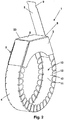
- the Fig. 1 to 6 show a holding device 1, wherein the two closure elements 2, 3 are connected or connected to each other, wherein the first closure element 2 has a traction body 5 or is formed as such, wherein the second closure member 3 has a recess 6 through which the tension member 5 to Reduction of the outer and / or inner circumference of the holding device 1 is pulled or pulled through, and wherein the tension member 5 is wound or wound up and rests on a abutment 8 during winding or in the wound state.
- the second closure element 3 is formed as a hood 23, wherein in the hood 23, the recess 6 is formed.
- the Fig. 1 to 4 show concretely a holding device 1 for fastening an insulation, not shown, comprising a first end to which a first closure element 2 is associated, a second end to which a second closure element 3 is assigned, and a bendable belt section 4 which is located between the closure elements 2, 3, wherein the two ends by an interaction of the closure elements 2, 3 are connected or connected to each other, wherein the first closure member 2 has a traction body 5 and wherein the second closure member 3 has a recess 6 through which the tension member 5 is pulled through or pulled through ,
- the Fig. 1 to 3 show that the tension body 5 can be wound up and its outer surface 7 bears against an abutment 8 of the second closure element 3 during winding.
- the tension body 5 can be wound up and lies on the abutment 8 during winding and is supported on it.
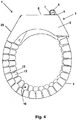
- Fig. 4 shows that the tension body 5 is wound and its outer surface 7 rests in the wound state on an abutment 8 of the second closure element 3. In that regard, the tension body 5 is wound and lies in the wound state on the abutment 8 and is supported on this.
- Fig. 4 shows concretely that the tension body 5 is wound spirally.
- the tensile body 5 according to Fig. 1 to 3 is manually or by means of a cordless screwdriver spirally wound and in the in Fig. 4 shown state can be brought.
- the traction body 5 is formed as an elongate strip or elongated tongue or strip-like or tongue-like. At its free end, it has a constriction 9, which allows easy gripping and bending or winding by a tool.
- the tension body 5 and the material from which the belt portion 4 and the entire holding device 1 are made have a thickness of 0.5 mm.
- the Fig. 1 to 5 show that the belt portion 4 has a receptacle 10 for inserting or applying an insulation and forms this receptacle 10.
- the belt section 4 has an inner abutment base 11, from which support segments 12 protrude on both sides, which are spaced apart from one another by recesses 13.
- At least two support segments 12 are tapered in Abragecardi in width, with a lying between these recess 13 in Abrageraum so expanded that the support segments 12 can bend each other in bending the belt portion 4 to reduce the outer and / or inner circumference with their side edges and the recess 13 is reduced in width.
- the support segments 12 are spaced from each other by the recesses 13.
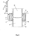
- the support segments 12 project from the abutment base 11, enclosing an angle of 80 to 100 ° therewith. This is in Fig. 5 shown particularly clearly.
- Several adjacent support segments 12 are each arranged on palisade-like on opposite longitudinal sides of the investment base 11. Between two adjacent support segments 12, a respective recess 13 in the form of a unilaterally open, V-shaped widening slot is formed.
- the recesses 13 can be introduced by punching processes or a laser.
- Fig. 7 shows that the holding device 1 is integrally formed from a metallic layer.
- the metallic layer is made of stainless steel.
- the metallic layer has a thickness of 0.5 mm.
- abragenden side elements can be bent due to a continuous edging and connected by riveting to the second closure element 3 and the hood 23.
- the support segments 12 can also be bent due to the edging to form a receptacle 10.
- the first closure element 2 and the tension body 5 are integrally formed and merge into one another.
- the tension body 5 opens into the first closure element 2 by the width of the tension member 5 increases. As a result, the pulling body 5 can only be pulled through the recess 6 with a certain length.
- Fig. 8 shows in the left view a rotatable pin-shaped tool 14 for fixing the holding device 1.
- the tool 14 comprises a gripping end 15 with a slot 16 open on one side, in which the pulling body 5 can be inserted, and an adapter end 17, which is formed as a hexagon 18.
- the gripping end 15 is used to grasp and winding the traction body 5.
- the adapter end 17 is connected to a rotatable or rotatable chuck.
- the adapter end 17 is provided with a hexagon 18. It is, however conceivable that the adapter end 17 is designed differently in order to be taken good by a tool can.
- a method for securing an insulation 19 by means of the holding device 1 can be carried out, wherein the first end of the holding device 1, which is associated with the first closure element 2, and the second end of the holding device 1, which the second closure element 3 assigned is, are interconnected, wherein the belt portion 4, which extends between the closure elements 2, 3, is bent, wherein the two ends are connected by an interaction of the closure elements 2, 3, by the pulling body 5 of the first closure element 2 through the recess 6 of the second closure element 3 is pulled, wherein the tension body 5 is wound to reduce the outer and inner circumference of the holding device 1 and to the determination thereof and wherein its outer surface 7 abuts during winding or in the wound state on an abutment 8 of the second closure element 3.
- the winding is done by rotating the tool 14, the slot 16 with the tension body 5 is engaged.
- Fig. 8 shows on the right side in a schematic view of an arrangement comprising two pipe ends 20, 21, which are gas-tight and firmly connected to each other by a V-band clamp 22, wherein the V-band clamp 22 is surrounded by an insulation 19 and the insulation 19 is received in the receptacle 10 of the holding device 1.
- the holding device 1 presses the insulation 19 radially against the V-band clamp 22 and surrounds both the V-band clamp 22 and the insulation 19 in the radial and axial directions in the manner of an outer jacket.
- the insulation 19 and the V-band clamp 22 are thereby protected against stone chipping, when the arrangement is arranged for example on an underbody of a motor vehicle.
- the pipe ends 20, 21 are each additionally insulated by an insulating jacket 24, which ends in each case within the holding device 1 in order to produce an almost complete isolation.
- the insulation 19 is connected to the holding device 1 at least at one point.
- the insulation 19 is fixed to the second closure element 3.
- the recess 6 in the second closure element 3 is formed as a slot surrounded on four sides.
- the slot or the recess 6 is elongated.
- the slot or the recess 6 is so narrow that the tension member 5 can be passed with little play. As a result, the tension body 5 can no longer slide back through the slot or the recess 6, even if it is wound only slightly, that is, with only a few windings.
- Fig. 9 shows a holding device 1 ', in which no tension body, but a screw 25 is used to connect the closure elements 2', 3 'together.
- the second closure element 3 ' is designed as a hood 23'.
- 10 to 14 show a further holding device 1 ", in which the two closure elements 2 ', 3' are connected to one another by a screw connection.
- a screw 25 is received with a threaded end of a screw in a counter-receptacle 26, and the screw 25 can be screwed to reduce the outer and / or inner circumference of the holding device 1 "in the screw counter-receptacle 26.
- the screw 25 is received with its threaded end of the screw in a rotatable screw counter-receptacle 26 and pivoted.
- the screw 25 can be suspended with a free end, which has a screw head, in a suspension bearing 27. After hanging, the holding device 1 "can be pressed against radially inner elements by screwing the screw 25 in the screw counter-receptacle 26.
- the rotatable screw counter receptacle 26 is assigned to the belt portion 4, namely fixed thereto.
- the suspension bearing 27 is the hood 23 'associated with, namely fixed to this.
- Fig. 14 shows the holding device 1 "in the rolled-up state with inserted insulation 19. There are shown with respect to surface slopes of the hood 23 'two angles a and b of 55 °.
- Fig. 15 shows that the insulation 19 has a lamination 28 which faces away from the abutment base 11 and is arranged radially inward.
- the lamination 28 is applied to an insulating material 30.
- the insulation 19 is partially connected by an adhesive 29 with the holding device 1 ".
- the holding device 1 "has in its hood 23 'a recess 6, by means of which a pulling body 5 could be pulled in.
- a combination of a screw connection and a connection by means of the pulling body 5 described here is conceivable.
Landscapes
- Engineering & Computer Science (AREA)
- General Engineering & Computer Science (AREA)
- Mechanical Engineering (AREA)
- Clamps And Clips (AREA)
- Thermal Insulation (AREA)
Claims (14)
- Dispositif de retenue (1,1',1") destiné à fixer un isolant (19) sur un collier à bande en V (22) ou sur un autre dispositif de liaison pour des embouts de tube (20, 21) à assembler, comprenant des éléments de fermeture (2, 2', 3, 3'), sachant que par action conjointe des éléments de fermeture (2, 2', 3, 3'), la périphérie extérieure et/ou intérieure du dispositif de retenue (1, 1', 1") peut être réduit, et comprenant une section de ceinture (4) flexible, sachant que la section de ceinture (4) peut être posée en tant que partie d'une enveloppe extérieure ou à la manière d'une enveloppe extérieure autour d'un isolant (19), sachant que les éléments de fermeture (2, 3) peuvent être reliés ou sont reliés les uns aux autres,
sachant qu'un premier élément de fermeture (2) comporte un corps de traction (5) ou est constitué comme tel et sachant qu'un deuxième élément de fermeture (3) comporte un évidement (6) à travers lequel le corps de traction (5) peut être passé ou est passé pour réduire la périphérie extérieure et/ou intérieure du dispositif de retenue (1),
caractérisé en ce que le corps de traction (5) peut être enroulé ou est enroulé et vient s'appliquer lors de l'enroulement ou à l'état enroulé sur une butée (8) et en ce que le corps de traction (5) peut être enroulé ou est enroulé en forme de spirale. - Dispositif de retenue selon la revendication 1, caractérisé en ce que la section de ceinture (4) est reliée et/ou peut être reliée indirectement ou directement à une calotte (23, 23') pour loger une saillie ou fermeture d'un collier à bande en V (22) ou d'un autre dispositif de liaison pour les embouts de tube (20, 21).
- Dispositif de retenue selon la revendication 1 ou 2, caractérisé en ce que le corps de traction (5) est constitué comme une bande longitudinale ou languette longitudinale ou en forme de bande ou de languette.
- Dispositif de retenue selon l'une quelconque des revendications 1 à 3, caractérisé en ce que le deuxième élément de fermeture (3) est constitué comme une calotte (23), sachant que l'évidement (6) est constitué dans la calotte (23).
- Dispositif de retenue selon l'une quelconque des revendications précédentes, caractérisé en ce que la section de ceinture (4) comporte ou constitue un logement (10) pour l'insertion ou la pose d'un isolant (19), sachant que la section de ceinture (4) comporte une base d'appui intérieure (11) de laquelle dépassent des deux côtés des segments de soutien (12), lesquels sont à distance les uns des autres par des évidements (13) à distances les unes des autres.
- Dispositif de retenue selon la revendication 5, caractérisé en ce qu'au moins deux segments de soutien (12) diminuent dans leur largeur dans la direction de dépassement, sachant qu'un évidement (13) situé entre ceux-ci s'élargit en direction de dépassement de telle manière que les segments de soutien (12) peuvent se rapprocher les uns des autres avec leurs bords latéraux à la flexion de la section de ceinture (4) pour réduire la périphérie extérieure et/ou intérieure et de ce fait l'évidement (13) se réduit dans sa largeur.
- Dispositif de retenue selon l'une quelconque des revendications précédentes, caractérisé en ce qu'un isolant (19) est relié au moins sur un côté au dispositif de retenue (1, 1', 1") et/ou en ce qu'un isolant (19) est fixé sur le deuxième élément de fermeture (3, 3').
- Dispositif de retenue selon l'une quelconque des revendications précédentes, caractérisé en ce que les deux éléments de fermeture (2', 3') peuvent être reliés l'un à l'autre par une liaison à vis, sachant qu'une vis (25) avec un embout de vis portant un filetage est logée dans un logement opposé à vis (26) et la vis (25) peut être vissée pour réduire la périphérie extérieure et/ou intérieure du dispositif de retenue (1', 1") dans le logement opposé à vis (26).
- Dispositif de retenue selon la revendication 8, caractérisé en ce que la vis (25) avec son embout de vis est logée dans un logement opposé à vis (26) pouvant tourner ou est logée pouvant pivoter et est accrochée ou peut être accrochée dans un support d'accrochage (27) avec une extrémité libre, laquelle comporte une tête de vis.
- Dispositif de retenue selon la revendication 9, caractérisé en ce que le logement opposé à vis (26) pouvant tourner est attribué au premier élément de fermeture (2') et/ou à la section de ceinture (4) et en ce que le support d'accrochage (27) est attribué au deuxième élément de fermeture (3') et/ou à la calotte (23').
- Dispositif de retenue selon l'une quelconque des revendications précédentes, caractérisé en ce que l'isolant (19) comporte un laminage (28), lequel est disposé opposé à la base d'appui (11) et/ou radialement vers l'intérieur.
- Dispositif de retenue selon l'une quelconque des revendications précédentes, caractérisé en ce que l'isolant (19) est relié par zone par un adhésif (29) au dispositif de retenue (1").
- Procédé de fixation d'un isolant (19) au moyen d'un dispositif de retenue (1, 1', 1") selon le préambule de la revendication 1 ou selon l'une quelconque des revendications 1 à 12 comprenant les étapes suivantes :- la première extrémité du dispositif de retenue (1) à laquelle est attribué le premier élément de fermeture (2) et la deuxième extrémité du dispositif de retenue (1) à laquelle est attribué le deuxième élément de fermeture (3), sont reliées l'une à l'autre,- sachant que la section de ceinture (4), laquelle s'étend entre les éléments de fermeture (2, 3), est cintrée,- sachant que les deux extrémités sont reliées par une action conjointe des éléments de fermeture (2, 3), le corps de traction (5) du premier élément de fermeture (2) ou le corps de traction (5) en tant que premier élément de fermeture (2) étant tiré à travers l'évidement (6) du deuxième élément de fermeture (3),- sachant que le corps de traction (5) est enroulé en forme de spirale pour réduire la périphérie extérieure et/ou intérieure du dispositif de retenue (1) et pour la fixation de celui-ci, et- sachant que le corps de traction (5) vient s'appliquer lors de l'enroulement ou à l'état enroulé sur une butée (8) du dispositif de retenue (1).
- Procédé selon la revendication 13, caractérisé par un passage avec un outil (14) pour fixer un dispositif de retenue (1) selon l'une quelconque des revendications 1 à 12, comprenant une extrémité d'engagement (15) avec une fente (16) ouverte unilatéralement dans laquelle le corps de traction (5) peut être rentré, et une extrémité d'adaptation (17).
Priority Applications (1)
| Application Number | Priority Date | Filing Date | Title |
|---|---|---|---|
| EP19184309.3A EP3569916B1 (fr) | 2016-04-25 | 2017-04-11 | Dispositif de maintien permettant de fixer une isolation |
Applications Claiming Priority (3)
| Application Number | Priority Date | Filing Date | Title |
|---|---|---|---|
| DE102016107637.6A DE102016107637A1 (de) | 2016-04-25 | 2016-04-25 | Haltevorrichtung zum Befestigen einer Isolierung und Werkzeug hierfür |
| DE202016002956.9U DE202016002956U1 (de) | 2016-04-25 | 2016-05-10 | Haltevorrichtung zum Befestigen einer lsolierung und Werkzeug hierfür |
| DE202016002955.0U DE202016002955U1 (de) | 2016-04-25 | 2016-05-10 | Haltevorrichtung zum Befestigen einer lsolierung und Werkzeug hierfür |
Related Child Applications (2)
| Application Number | Title | Priority Date | Filing Date |
|---|---|---|---|
| EP19184309.3A Division EP3569916B1 (fr) | 2016-04-25 | 2017-04-11 | Dispositif de maintien permettant de fixer une isolation |
| EP19184309.3A Division-Into EP3569916B1 (fr) | 2016-04-25 | 2017-04-11 | Dispositif de maintien permettant de fixer une isolation |
Publications (2)
| Publication Number | Publication Date |
|---|---|
| EP3239586A1 EP3239586A1 (fr) | 2017-11-01 |
| EP3239586B1 true EP3239586B1 (fr) | 2019-08-28 |
Family
ID=56293371
Family Applications (2)
| Application Number | Title | Priority Date | Filing Date |
|---|---|---|---|
| EP19184309.3A Active EP3569916B1 (fr) | 2016-04-25 | 2017-04-11 | Dispositif de maintien permettant de fixer une isolation |
| EP17000616.7A Active EP3239586B1 (fr) | 2016-04-25 | 2017-04-11 | Dispositif de retenue destiné à fixer un isolant |
Family Applications Before (1)
| Application Number | Title | Priority Date | Filing Date |
|---|---|---|---|
| EP19184309.3A Active EP3569916B1 (fr) | 2016-04-25 | 2017-04-11 | Dispositif de maintien permettant de fixer une isolation |
Country Status (3)
| Country | Link |
|---|---|
| US (1) | US10612706B2 (fr) |
| EP (2) | EP3569916B1 (fr) |
| DE (3) | DE102016107637A1 (fr) |
Cited By (1)
| Publication number | Priority date | Publication date | Assignee | Title |
|---|---|---|---|---|
| EP3992506A1 (fr) | 2020-10-29 | 2022-05-04 | tmax Holding GmbH | Élément et dispositif d'isolation thermique et/ou de dissipation de chaleur et de refroidissement |
Families Citing this family (7)
| Publication number | Priority date | Publication date | Assignee | Title |
|---|---|---|---|---|
| DE102016111117A1 (de) * | 2016-06-17 | 2017-12-21 | Norma Germany Gmbh | Schelle mit thermischer Isolationsschicht |
| GB2559412B (en) | 2017-02-06 | 2019-05-15 | Ford Global Tech Llc | Heatshield for a band clamp |
| US11271378B2 (en) | 2018-12-28 | 2022-03-08 | Commscope Technologies Llc | Devices and methods for holding cables |
| US11268635B2 (en) | 2018-12-28 | 2022-03-08 | Commscope Technologies Llc | Devices and methods for holding cables |
| DE102019121432A1 (de) | 2019-08-08 | 2021-02-11 | Norma Germany Gmbh | Schellenanordnung mit einer Hitzeschutzeinrichtung |
| CN110848505B (zh) * | 2019-12-20 | 2025-03-14 | 北京吉瑞普管道技术有限公司 | 一种遇火膨胀装置 |
| US11898669B2 (en) * | 2022-06-08 | 2024-02-13 | International Engine Intellectual Property Company, Llc | System for reducing band clamp failure |
Family Cites Families (15)
| Publication number | Priority date | Publication date | Assignee | Title |
|---|---|---|---|---|
| US1467254A (en) * | 1921-02-21 | 1923-09-04 | Tarbet Albert | Self-locking milk-can cover |
| US2395745A (en) * | 1942-11-16 | 1946-02-26 | James T King | Joint and clamp construction |
| GB616170A (en) * | 1945-04-04 | 1949-01-18 | Fridolf Henning Brunnzell | A flexible band for producing protective covers |
| US4492393A (en) * | 1981-08-31 | 1985-01-08 | Parker Hannifin Corporation | Pipe restraint device |
| US4402113A (en) * | 1981-12-30 | 1983-09-06 | Communications Technology Corporation | Flexible clamp for hose, cable and the like |
| JPS59126807U (ja) * | 1983-02-07 | 1984-08-27 | 株式会社リコー | カ−トリツジシ−ルの開封具 |
| JPS6038992U (ja) * | 1983-08-25 | 1985-03-18 | 川崎重工業株式会社 | 伸縮管継手 |
| US5103609A (en) | 1990-11-15 | 1992-04-14 | Minnesota Mining & Manufacturing Company | Intumescable fire stop device |
| DE4325757A1 (de) | 1993-07-31 | 1995-02-02 | Gruenau Gmbh Chem Fab | Rohrschott mit einem um ein Rohr biegbaren Blechmantel |
| US6685229B2 (en) * | 2001-11-15 | 2004-02-03 | Mpdi | Hose and clamp assembly |
| JP4563158B2 (ja) * | 2004-12-03 | 2010-10-13 | 株式会社ミハマ | 締付けバンド |
| BRPI0609395B1 (pt) * | 2005-03-04 | 2018-11-06 | Breeze Torca Products Llc | abraçadeira de pino-t |
| DE102005057670B4 (de) * | 2005-12-01 | 2009-12-10 | J. Eberspächer GmbH & Co. KG | Rohrverbindung |
| DE102008034435B4 (de) | 2008-07-24 | 2019-12-24 | Norma Germany Gmbh | Flammschutzeinrichtung für eine Rohrkupplung |
| US9032592B2 (en) * | 2009-04-14 | 2015-05-19 | Voss Industries, Inc. | Band clamp |
-
2016
- 2016-04-25 DE DE102016107637.6A patent/DE102016107637A1/de not_active Withdrawn
- 2016-05-10 DE DE202016002956.9U patent/DE202016002956U1/de active Active
- 2016-05-10 DE DE202016002955.0U patent/DE202016002955U1/de active Active
-
2017
- 2017-04-11 EP EP19184309.3A patent/EP3569916B1/fr active Active
- 2017-04-11 EP EP17000616.7A patent/EP3239586B1/fr active Active
- 2017-04-24 US US15/495,816 patent/US10612706B2/en active Active
Non-Patent Citations (1)
| Title |
|---|
| None * |
Cited By (1)
| Publication number | Priority date | Publication date | Assignee | Title |
|---|---|---|---|---|
| EP3992506A1 (fr) | 2020-10-29 | 2022-05-04 | tmax Holding GmbH | Élément et dispositif d'isolation thermique et/ou de dissipation de chaleur et de refroidissement |
Also Published As
| Publication number | Publication date |
|---|---|
| EP3569916B1 (fr) | 2023-02-22 |
| DE102016107637A1 (de) | 2017-10-26 |
| US20170307117A1 (en) | 2017-10-26 |
| EP3569916A1 (fr) | 2019-11-20 |
| DE202016002956U1 (de) | 2016-06-14 |
| EP3239586A1 (fr) | 2017-11-01 |
| US10612706B2 (en) | 2020-04-07 |
| DE202016002955U1 (de) | 2016-06-14 |
Similar Documents
| Publication | Publication Date | Title |
|---|---|---|
| EP3239586B1 (fr) | Dispositif de retenue destiné à fixer un isolant | |
| DE102006020407B3 (de) | Schelle zum Befestigen eines rohr- oder schlauchförmigen Gegenstandes | |
| EP2587106B1 (fr) | Manchette pare-feu | |
| EP2908039B1 (fr) | Système de fixation | |
| DE102011005598A1 (de) | Befestigungsvorrichtung zur Anordnung an einer Montageschiene | |
| DE112010002322T5 (de) | Selbst zentrierendes Klebeband | |
| DE4411220A1 (de) | Rohrmanschette | |
| DE102015004019A1 (de) | Schutzgitter; Verfahren zur Herstellung eines Schutzgitters für Lüfter | |
| EP2216575B1 (fr) | Elément de fixation, dispositif ainsi que procédé de fixation d'un tuyau flexible | |
| EP3406501B1 (fr) | Véhicule pourvu d'au moins un dispositif de canal et procédé permettant d'équiper un véhicule d'un dispositif de canal | |
| DE102019121432A1 (de) | Schellenanordnung mit einer Hitzeschutzeinrichtung | |
| WO2019211053A1 (fr) | Collier de serrage | |
| DE4108852A1 (de) | Spannschelle mit einem an seinen raendern bereichsweise wellenfoermigen spannband | |
| AT519600B1 (de) | Haltevorrichtung für ein kabel oder rohr | |
| DE202015002378U1 (de) | Schutzgitter | |
| DE102012110659B4 (de) | Zwischenstütze, Sicherungssysteme und Verfahren zum Anbringen einer Zwischenstütze | |
| EP2806506B1 (fr) | Capot disposé sur un élément de connecteur multibroches | |
| DE202009000508U1 (de) | Rohrklemme | |
| EP3239576B1 (fr) | Dispositif de retenue pour un câble ou un tuyau | |
| DE19600812A1 (de) | Schutzanordnung mit zwei längsgeschlitzten Schutzrohren | |
| EP3477174B1 (fr) | Manchette de protection contre l'incendie ainsi que logement correspondant et traversée de paroi ou de plafond comportant ladite manchette de protection contre l'incendie | |
| EP3239577B1 (fr) | Dispositif de retenue pour un câble ou un tuyau | |
| EP1022528A2 (fr) | Dispositif de fixation | |
| DE3925171A1 (de) | Vorrichtung zum festhalten eines langkoerpers in einem vorbestimmten kruemmungsradius | |
| EP0430866A2 (fr) | Pièce de raccordement |
Legal Events
| Date | Code | Title | Description |
|---|---|---|---|
| PUAI | Public reference made under article 153(3) epc to a published international application that has entered the european phase |
Free format text: ORIGINAL CODE: 0009012 |
|
| STAA | Information on the status of an ep patent application or granted ep patent |
Free format text: STATUS: THE APPLICATION HAS BEEN PUBLISHED |
|
| STAA | Information on the status of an ep patent application or granted ep patent |
Free format text: STATUS: REQUEST FOR EXAMINATION WAS MADE |
|
| AK | Designated contracting states |
Kind code of ref document: A1 Designated state(s): AL AT BE BG CH CY CZ DE DK EE ES FI FR GB GR HR HU IE IS IT LI LT LU LV MC MK MT NL NO PL PT RO RS SE SI SK SM TR |
|
| AX | Request for extension of the european patent |
Extension state: BA ME |
|
| 17P | Request for examination filed |
Effective date: 20171005 |
|
| RBV | Designated contracting states (corrected) |
Designated state(s): AL AT BE BG CH CY CZ DE DK EE ES FI FR GB GR HR HU IE IS IT LI LT LU LV MC MK MT NL NO PL PT RO RS SE SI SK SM TR |
|
| GRAP | Despatch of communication of intention to grant a patent |
Free format text: ORIGINAL CODE: EPIDOSNIGR1 |
|
| STAA | Information on the status of an ep patent application or granted ep patent |
Free format text: STATUS: GRANT OF PATENT IS INTENDED |
|
| RIC1 | Information provided on ipc code assigned before grant |
Ipc: F16L 59/16 20060101AFI20190320BHEP Ipc: F16L 59/18 20060101ALI20190320BHEP |
|
| INTG | Intention to grant announced |
Effective date: 20190416 |
|
| GRAS | Grant fee paid |
Free format text: ORIGINAL CODE: EPIDOSNIGR3 |
|
| GRAA | (expected) grant |
Free format text: ORIGINAL CODE: 0009210 |
|
| STAA | Information on the status of an ep patent application or granted ep patent |
Free format text: STATUS: THE PATENT HAS BEEN GRANTED |
|
| AK | Designated contracting states |
Kind code of ref document: B1 Designated state(s): AL AT BE BG CH CY CZ DE DK EE ES FI FR GB GR HR HU IE IS IT LI LT LU LV MC MK MT NL NO PL PT RO RS SE SI SK SM TR |
|
| REG | Reference to a national code |
Ref country code: GB Ref legal event code: FG4D Free format text: NOT ENGLISH |
|
| REG | Reference to a national code |
Ref country code: CH Ref legal event code: EP |
|
| REG | Reference to a national code |
Ref country code: AT Ref legal event code: REF Ref document number: 1172843 Country of ref document: AT Kind code of ref document: T Effective date: 20190915 |
|
| REG | Reference to a national code |
Ref country code: IE Ref legal event code: FG4D Free format text: LANGUAGE OF EP DOCUMENT: GERMAN |
|
| REG | Reference to a national code |
Ref country code: DE Ref legal event code: R096 Ref document number: 502017002099 Country of ref document: DE |
|
| REG | Reference to a national code |
Ref country code: NL Ref legal event code: FP |
|
| REG | Reference to a national code |
Ref country code: CH Ref legal event code: NV Representative=s name: RAPISARDI INTELLECTUAL PROPERTY SA, CH |
|
| REG | Reference to a national code |
Ref country code: SE Ref legal event code: TRGR |
|
| REG | Reference to a national code |
Ref country code: LT Ref legal event code: MG4D |
|
| PG25 | Lapsed in a contracting state [announced via postgrant information from national office to epo] |
Ref country code: FI Free format text: LAPSE BECAUSE OF FAILURE TO SUBMIT A TRANSLATION OF THE DESCRIPTION OR TO PAY THE FEE WITHIN THE PRESCRIBED TIME-LIMIT Effective date: 20190828 Ref country code: HR Free format text: LAPSE BECAUSE OF FAILURE TO SUBMIT A TRANSLATION OF THE DESCRIPTION OR TO PAY THE FEE WITHIN THE PRESCRIBED TIME-LIMIT Effective date: 20190828 Ref country code: BG Free format text: LAPSE BECAUSE OF FAILURE TO SUBMIT A TRANSLATION OF THE DESCRIPTION OR TO PAY THE FEE WITHIN THE PRESCRIBED TIME-LIMIT Effective date: 20191128 Ref country code: PT Free format text: LAPSE BECAUSE OF FAILURE TO SUBMIT A TRANSLATION OF THE DESCRIPTION OR TO PAY THE FEE WITHIN THE PRESCRIBED TIME-LIMIT Effective date: 20191230 Ref country code: LT Free format text: LAPSE BECAUSE OF FAILURE TO SUBMIT A TRANSLATION OF THE DESCRIPTION OR TO PAY THE FEE WITHIN THE PRESCRIBED TIME-LIMIT Effective date: 20190828 Ref country code: NO Free format text: LAPSE BECAUSE OF FAILURE TO SUBMIT A TRANSLATION OF THE DESCRIPTION OR TO PAY THE FEE WITHIN THE PRESCRIBED TIME-LIMIT Effective date: 20191128 |
|
| PG25 | Lapsed in a contracting state [announced via postgrant information from national office to epo] |
Ref country code: AL Free format text: LAPSE BECAUSE OF FAILURE TO SUBMIT A TRANSLATION OF THE DESCRIPTION OR TO PAY THE FEE WITHIN THE PRESCRIBED TIME-LIMIT Effective date: 20190828 Ref country code: GR Free format text: LAPSE BECAUSE OF FAILURE TO SUBMIT A TRANSLATION OF THE DESCRIPTION OR TO PAY THE FEE WITHIN THE PRESCRIBED TIME-LIMIT Effective date: 20191129 Ref country code: RS Free format text: LAPSE BECAUSE OF FAILURE TO SUBMIT A TRANSLATION OF THE DESCRIPTION OR TO PAY THE FEE WITHIN THE PRESCRIBED TIME-LIMIT Effective date: 20190828 Ref country code: IS Free format text: LAPSE BECAUSE OF FAILURE TO SUBMIT A TRANSLATION OF THE DESCRIPTION OR TO PAY THE FEE WITHIN THE PRESCRIBED TIME-LIMIT Effective date: 20191228 Ref country code: LV Free format text: LAPSE BECAUSE OF FAILURE TO SUBMIT A TRANSLATION OF THE DESCRIPTION OR TO PAY THE FEE WITHIN THE PRESCRIBED TIME-LIMIT Effective date: 20190828 |
|
| PG25 | Lapsed in a contracting state [announced via postgrant information from national office to epo] |
Ref country code: TR Free format text: LAPSE BECAUSE OF FAILURE TO SUBMIT A TRANSLATION OF THE DESCRIPTION OR TO PAY THE FEE WITHIN THE PRESCRIBED TIME-LIMIT Effective date: 20190828 |
|
| PG25 | Lapsed in a contracting state [announced via postgrant information from national office to epo] |
Ref country code: EE Free format text: LAPSE BECAUSE OF FAILURE TO SUBMIT A TRANSLATION OF THE DESCRIPTION OR TO PAY THE FEE WITHIN THE PRESCRIBED TIME-LIMIT Effective date: 20190828 Ref country code: DK Free format text: LAPSE BECAUSE OF FAILURE TO SUBMIT A TRANSLATION OF THE DESCRIPTION OR TO PAY THE FEE WITHIN THE PRESCRIBED TIME-LIMIT Effective date: 20190828 Ref country code: PL Free format text: LAPSE BECAUSE OF FAILURE TO SUBMIT A TRANSLATION OF THE DESCRIPTION OR TO PAY THE FEE WITHIN THE PRESCRIBED TIME-LIMIT Effective date: 20190828 Ref country code: RO Free format text: LAPSE BECAUSE OF FAILURE TO SUBMIT A TRANSLATION OF THE DESCRIPTION OR TO PAY THE FEE WITHIN THE PRESCRIBED TIME-LIMIT Effective date: 20190828 |
|
| PG25 | Lapsed in a contracting state [announced via postgrant information from national office to epo] |
Ref country code: CZ Free format text: LAPSE BECAUSE OF FAILURE TO SUBMIT A TRANSLATION OF THE DESCRIPTION OR TO PAY THE FEE WITHIN THE PRESCRIBED TIME-LIMIT Effective date: 20190828 Ref country code: SK Free format text: LAPSE BECAUSE OF FAILURE TO SUBMIT A TRANSLATION OF THE DESCRIPTION OR TO PAY THE FEE WITHIN THE PRESCRIBED TIME-LIMIT Effective date: 20190828 Ref country code: IS Free format text: LAPSE BECAUSE OF FAILURE TO SUBMIT A TRANSLATION OF THE DESCRIPTION OR TO PAY THE FEE WITHIN THE PRESCRIBED TIME-LIMIT Effective date: 20200224 Ref country code: SM Free format text: LAPSE BECAUSE OF FAILURE TO SUBMIT A TRANSLATION OF THE DESCRIPTION OR TO PAY THE FEE WITHIN THE PRESCRIBED TIME-LIMIT Effective date: 20190828 |
|
| REG | Reference to a national code |
Ref country code: DE Ref legal event code: R097 Ref document number: 502017002099 Country of ref document: DE |
|
| PLBE | No opposition filed within time limit |
Free format text: ORIGINAL CODE: 0009261 |
|
| STAA | Information on the status of an ep patent application or granted ep patent |
Free format text: STATUS: NO OPPOSITION FILED WITHIN TIME LIMIT |
|
| PG2D | Information on lapse in contracting state deleted |
Ref country code: IS |
|
| 26N | No opposition filed |
Effective date: 20200603 |
|
| PG25 | Lapsed in a contracting state [announced via postgrant information from national office to epo] |
Ref country code: SI Free format text: LAPSE BECAUSE OF FAILURE TO SUBMIT A TRANSLATION OF THE DESCRIPTION OR TO PAY THE FEE WITHIN THE PRESCRIBED TIME-LIMIT Effective date: 20190828 |
|
| PG25 | Lapsed in a contracting state [announced via postgrant information from national office to epo] |
Ref country code: ES Free format text: LAPSE BECAUSE OF FAILURE TO SUBMIT A TRANSLATION OF THE DESCRIPTION OR TO PAY THE FEE WITHIN THE PRESCRIBED TIME-LIMIT Effective date: 20190828 |
|
| PG25 | Lapsed in a contracting state [announced via postgrant information from national office to epo] |
Ref country code: MC Free format text: LAPSE BECAUSE OF FAILURE TO SUBMIT A TRANSLATION OF THE DESCRIPTION OR TO PAY THE FEE WITHIN THE PRESCRIBED TIME-LIMIT Effective date: 20190828 |
|
| PG25 | Lapsed in a contracting state [announced via postgrant information from national office to epo] |
Ref country code: LU Free format text: LAPSE BECAUSE OF NON-PAYMENT OF DUE FEES Effective date: 20200411 |
|
| REG | Reference to a national code |
Ref country code: BE Ref legal event code: MM Effective date: 20200430 |
|
| PG25 | Lapsed in a contracting state [announced via postgrant information from national office to epo] |
Ref country code: BE Free format text: LAPSE BECAUSE OF NON-PAYMENT OF DUE FEES Effective date: 20200430 |
|
| PG25 | Lapsed in a contracting state [announced via postgrant information from national office to epo] |
Ref country code: IE Free format text: LAPSE BECAUSE OF NON-PAYMENT OF DUE FEES Effective date: 20200411 |
|
| PG25 | Lapsed in a contracting state [announced via postgrant information from national office to epo] |
Ref country code: MT Free format text: LAPSE BECAUSE OF FAILURE TO SUBMIT A TRANSLATION OF THE DESCRIPTION OR TO PAY THE FEE WITHIN THE PRESCRIBED TIME-LIMIT Effective date: 20190828 Ref country code: CY Free format text: LAPSE BECAUSE OF FAILURE TO SUBMIT A TRANSLATION OF THE DESCRIPTION OR TO PAY THE FEE WITHIN THE PRESCRIBED TIME-LIMIT Effective date: 20190828 |
|
| PG25 | Lapsed in a contracting state [announced via postgrant information from national office to epo] |
Ref country code: MK Free format text: LAPSE BECAUSE OF FAILURE TO SUBMIT A TRANSLATION OF THE DESCRIPTION OR TO PAY THE FEE WITHIN THE PRESCRIBED TIME-LIMIT Effective date: 20190828 |
|
| P01 | Opt-out of the competence of the unified patent court (upc) registered |
Effective date: 20230417 |
|
| PGFP | Annual fee paid to national office [announced via postgrant information from national office to epo] |
Ref country code: NL Payment date: 20250422 Year of fee payment: 9 |
|
| PGFP | Annual fee paid to national office [announced via postgrant information from national office to epo] |
Ref country code: DE Payment date: 20250417 Year of fee payment: 9 |
|
| PGFP | Annual fee paid to national office [announced via postgrant information from national office to epo] |
Ref country code: IT Payment date: 20250430 Year of fee payment: 9 |
|
| PGFP | Annual fee paid to national office [announced via postgrant information from national office to epo] |
Ref country code: FR Payment date: 20250422 Year of fee payment: 9 |
|
| PGFP | Annual fee paid to national office [announced via postgrant information from national office to epo] |
Ref country code: CH Payment date: 20250501 Year of fee payment: 9 |
|
| PGFP | Annual fee paid to national office [announced via postgrant information from national office to epo] |
Ref country code: AT Payment date: 20250416 Year of fee payment: 9 |
|
| PGFP | Annual fee paid to national office [announced via postgrant information from national office to epo] |
Ref country code: SE Payment date: 20250423 Year of fee payment: 9 |
|
| REG | Reference to a national code |
Ref country code: DE Ref legal event code: R082 Ref document number: 502017002099 Country of ref document: DE Representative=s name: WESCH, ARNO, DR. RER. NAT., DE |
|
| PGFP | Annual fee paid to national office [announced via postgrant information from national office to epo] |
Ref country code: GB Payment date: 20260324 Year of fee payment: 10 |