EP3406501B1 - Véhicule pourvu d'au moins un dispositif de canal et procédé permettant d'équiper un véhicule d'un dispositif de canal - Google Patents
Véhicule pourvu d'au moins un dispositif de canal et procédé permettant d'équiper un véhicule d'un dispositif de canal Download PDFInfo
- Publication number
- EP3406501B1 EP3406501B1 EP18172654.8A EP18172654A EP3406501B1 EP 3406501 B1 EP3406501 B1 EP 3406501B1 EP 18172654 A EP18172654 A EP 18172654A EP 3406501 B1 EP3406501 B1 EP 3406501B1
- Authority
- EP
- European Patent Office
- Prior art keywords
- vehicle
- channel
- channel element
- electrical line
- deflection
- Prior art date
- Legal status (The legal status is an assumption and is not a legal conclusion. Google has not performed a legal analysis and makes no representation as to the accuracy of the status listed.)
- Active
Links
Images


Classifications
-
- B—PERFORMING OPERATIONS; TRANSPORTING
- B61—RAILWAYS
- B61F—RAIL VEHICLE SUSPENSIONS, e.g. UNDERFRAMES, BOGIES OR ARRANGEMENTS OF WHEEL AXLES; RAIL VEHICLES FOR USE ON TRACKS OF DIFFERENT WIDTH; PREVENTING DERAILING OF RAIL VEHICLES; WHEEL GUARDS, OBSTRUCTION REMOVERS OR THE LIKE FOR RAIL VEHICLES
- B61F1/00—Underframes
-
- B—PERFORMING OPERATIONS; TRANSPORTING
- B60—VEHICLES IN GENERAL
- B60R—VEHICLES, VEHICLE FITTINGS, OR VEHICLE PARTS, NOT OTHERWISE PROVIDED FOR
- B60R16/00—Electric or fluid circuits specially adapted for vehicles and not otherwise provided for; Arrangement of elements of electric or fluid circuits specially adapted for vehicles and not otherwise provided for
- B60R16/02—Electric or fluid circuits specially adapted for vehicles and not otherwise provided for; Arrangement of elements of electric or fluid circuits specially adapted for vehicles and not otherwise provided for electric constitutive elements
- B60R16/0207—Wire harnesses
- B60R16/0215—Protecting, fastening and routing means therefor
-
- B—PERFORMING OPERATIONS; TRANSPORTING
- B61—RAILWAYS
- B61D—BODY DETAILS OR KINDS OF RAILWAY VEHICLES
- B61D17/00—Construction details of vehicle bodies
- B61D17/04—Construction details of vehicle bodies with bodies of metal; with composite, e.g. metal and wood body structures
- B61D17/10—Floors
-
- H—ELECTRICITY
- H02—GENERATION; CONVERSION OR DISTRIBUTION OF ELECTRIC POWER
- H02G—INSTALLATION OF ELECTRIC CABLES OR LINES, OR OF COMBINED OPTICAL AND ELECTRIC CABLES OR LINES
- H02G3/00—Installations of electric cables or lines or protective tubing therefor in or on buildings, equivalent structures or vehicles
- H02G3/02—Details
- H02G3/04—Protective tubing or conduits, e.g. cable ladders or cable troughs
- H02G3/0437—Channels
-
- H—ELECTRICITY
- H02—GENERATION; CONVERSION OR DISTRIBUTION OF ELECTRIC POWER
- H02G—INSTALLATION OF ELECTRIC CABLES OR LINES, OR OF COMBINED OPTICAL AND ELECTRIC CABLES OR LINES
- H02G3/00—Installations of electric cables or lines or protective tubing therefor in or on buildings, equivalent structures or vehicles
- H02G3/30—Installations of cables or lines on walls, floors or ceilings
- H02G3/34—Installations of cables or lines on walls, floors or ceilings using separate protective tubing
Definitions
- the invention relates to a vehicle with at least one duct device and a method for equipping a vehicle with a duct device.
- a high-voltage cable is laid in a vehicle in a section in a longitudinal direction of the vehicle.
- the high-voltage cable runs along an underfloor area of a vehicle and is attached to it.
- the high-voltage cable is routed in a tube in the underfloor area.
- the high-voltage cable must therefore be threaded into the pipe, which means that it takes more time.
- the pamphlet WO2011 / 114801 A1 describes a vehicle with a bundle of high-voltage lines, which is guided in a tube with a semicircular cross-section.
- the tube has flange sections which are fastened to a vehicle floor by means of fastening elements.
- a spring which presses the high-voltage lines against a wall of the pipe, can be arranged inside the pipe.
- the disadvantage here is that different components are required for routing the high-voltage lines and a spring action, which increases the manufacturing and assembly costs.
- the spring is flexible, so that positioning security is low.
- the pamphlet EP1767426 A2 describes a vehicle with at least one conduit which extends in a conduit which is arranged below the body of the vehicle, from one end of the vehicle to the other end of the vehicle.
- the pamphlet CN 201758266 U discloses a V-shaped channel for covering an electrical cable. Angled side sections with bores are provided on the channel and are fastened to a floor by means of fastening elements.
- the channel protects the electrical cable and prevents accidents at work, such as tripping accidents.
- a disadvantage is that the channel can only be used for static arrangements, because there is no device that could hold the cable in position under dynamic loads, such as vibrations.
- the pamphlet RU161654 U1 relates to a cable clamp for one or more electrical lines that can accommodate cables or cable bundles with different cross-sectional dimensions and is fastened to a base by means of screws.
- One disadvantage is that the cable clamp can only fix the cable or cable bundle at individual points. A guide and protection of the cable or cable bundle is missing between these points.
- the invention is therefore based on the object of creating a vehicle and a method in which an electrical line can be installed simply and quickly and is safely positioned, protected and guided during operation.
- the object is achieved in a vehicle with at least one duct device in which a single electrical line is routed, the vehicle having an underbody device with at least one straight area and at least one deflection area and the duct device comprising at least one duct element and at least one fastening element, wherein the channel element is fastened to the rectilinear region of the underbody device by means of the fastening element.
- the channel element is spaced from the rectilinear region of the underbody device, and the electrical line protrudes radially out of an opening region of the channel element.
- the electrical line can be preassembled quickly and easily in the at least one channel element. There is no need for threading into a tube, as is known from the prior art.
- the channel element protects and guides the electrical line along the straight area of the sub-floor.
- the channel element corresponds to a cable channel that is open in a longitudinal direction and has a length that is greater than a width of the cable channel or of the channel element.
- a straight-line area is an area in which the electric wire is routed in a straight line.
- the electrical line is routed in a straight line within a tolerance range and deviates from a straight line in the purely mathematical sense.
- the channel element together with the straight area of the underbody device, forms a three-point mount for the electrical Line off.
- the three-point mounting enables a clamping effect with the help of a simple design and geometry.
- the electrical line can rest against the duct element at a first point and at a second point and can rest against the straight area of the underbody device at a third point.
- the first position, the second position and the third position are particularly suitable for the formation of a three-point mounting.
- the channel element has at least one first V-shaped area.
- the V-shaped area forms a stable cross-sectional shape and enables drainage of the channel element.
- the V-shaped area contributes to a stable three-point support.
- the channel element can have two parallel sections which adjoin the first V-shaped area.
- Such a geometry of the channel element enables good guidance of the electrical line.
- the channel element can have two inwardly inclined sections which adjoin the parallel sections. As a result, a spring action is achieved with respect to the electrical line, which holds the electrical line in position.
- the opening area is expediently narrower than a diameter of the electrical line. This can prevent the electrical line from falling out of the duct element during assembly.
- edges along the opening area of the channel element can each have a flanging and / or at least one end of the channel element in at least one edge protection element.
- the flanging and the edge protection element prevent the edges of the duct element from scratching the electrical cable or causing injury to people.
- the channel element and the fastening element are separate components and / or a length of the channel element is greater than a width of the channel element. This reduces the manufacturing effort and the channel element and the fastening elements can be flexibly mounted. The ratio of the length and width of the channel element ensures that the electrical line is guided.
- the fastening element preferably has a second V-shaped area and rests on the outside of the first V-shaped area of the channel element and / or the fastening element is displaceable along the channel element.
- a V-shaped form fit improves the clamping effect on the electrical line.
- the fastening element can be mounted anywhere along the channel element
- the channel device comprises at least one deflection element in the deflection area, which encloses the electrical line together with the deflection area and / or partially covers the channel element.
- the deflection element ensures protection of the electrical line in areas that are exposed to high mechanical stress, e.g. in an area of the vehicle's wheels that kick up loose material from a route.
- the deflecting element partially covers the channel element and thereby enables manufacturing and assembly tolerances to be compensated.
- the deflecting element can have at least one angle, preferably two 90 ° angles including a tolerance range in each case, and be fastened to the deflecting region.
- the angled element has a simple and stable geometry and is easy to manufacture.
- the vehicle can be a rail vehicle.
- the invention is particularly advantageous since the electrical line has a great length and pre-assembly results in considerable time savings.
- the object is achieved in a method for equipping a vehicle with the duct device.
- the electrical line is inserted into at least one channel element and then the channel element is attached to the underfloor device in at least one straight area by means of the fastening element, the electrical line being clamped between the channel element and the straight area of the underbody device. This process enables simple assembly or pre-assembly and the electrical line is securely positioned.
- the at least one deflection element can be fastened to the at least one deflection region of the underbody device. This also protects the electrical line in the deflection areas.
- Fig. 1 shows schematically a vehicle 10 according to the invention, which here corresponds to a rail vehicle, with an electrical line 30, which here corresponds to a high-voltage cable. Starting from a roof area 12, the electrical line 30 runs through an interior area 11 and then along an underbody device 20.
- the electrical line 30 is laid unprotected with block clamps, not shown here.
- the electrical line 30 is completely metal-enclosed and fastened with block clamps, also not shown.
- the electrical line 30 runs within a into the Figs. 2 to 6 channel device 40 shown which is attached to the underbody device 20.
- a longitudinal direction x, one The transverse direction y and a perpendicular direction z denote in the Figs. 1 to 5 Reference directions of the vehicle 10.
- FIG. 13 is a perspective detail A from the underbody device 20 of the vehicle 10 in FIG Fig. 1 shown schematically.
- the underbody device 20 here has, for example, three straight areas 21, 27 and 29.
- the rectilinear areas 21, 27 and 29 are areas in which the electrical line 30 is guided in a straight line.
- the electrical line 30 is guided in a straight line within a tolerance range and deviates from a straight course in the purely mathematical sense.
- the underbody device 20 comprises two deflection areas 22 and 28, in which the electrical line 30 is guided in an arc.
- a duct device 40 is arranged on the underbody device 20.
- the channel device 40 comprises a channel element 41 in a rectilinear area 21, a deflecting element 100 in a deflecting area 22, a channel element 44 in a rectilinear area 27, a deflecting element 103 in a deflecting area 28 and a channel element 45 in a straight area 29.
- the channel elements 41 14, 44 and 45 are fastened to the underbody device 20 with fastening elements 80.
- there are further rectilinear areas (not shown) with channel elements (not shown) and further deflecting areas (not shown) with deflecting elements (not shown) which are each also parts of the channel device 40.
- channel element 41 is described, the structure of which corresponds to the channel elements 44 and 45 as well as all channel elements not shown.
- the channel elements 41, 44 and 45 have different lengths.
- the channel elements not shown can also have different lengths.
- the deflecting element 100 is also described below, which in cross section corresponds to the deflecting element 103 and all of the deflecting elements not shown.
- the electrical line 30 is curved in a clockwise direction with respect to the transverse direction y.
- the electrical line 30 is curved counterclockwise with respect to the transverse direction y.
- the deflecting elements (not shown) can be curved clockwise or counterclockwise with respect to the transverse direction y, depending on the course of the underbody device 20.
- Fig. 3 is the channel element 41 in the section plane BB in Fig. 2 shown in detail.
- the electrical line 30 is arranged in the channel element 41.
- the channel element 41 is fastened to rails 23 and 24 of the underbody device 20 by means of a fastening element 80 and screw connections 82 and 83.
- the rails 23 and 24 are here C-rails, but can also be designed differently.
- the channel element 41 is fastened to the rails 23 and 24 or to other rails of the underbody device 20 by at least one further fastening element 80.
- the channel element 41 has an opening region 42 from which the electrical line 30 protrudes in the vertical direction z.
- the opening area 42 is narrower than a diameter D of the electrical line 30.
- the channel element 41 has a first V-shaped area 43 in which the electrical line 30 rests at a first point 71 and a second point 72. At a third point 73, the electrical line 30 meets the underbody device 20.
- the first, second and third points 71, 72 and 73 together form a three-point receptacle for the electrical line 30.
- the fastening element 80 has a second V-shaped region 81, which from the outside rests against the first V-shaped region 43 of the channel element 41.
- An air gap 84 is located between the fastening element 80 and the rails 23 and 24.
- Fig. 4 is, based on the sectional view in Fig. 3 , a perspective view of the channel element 41 with the electrical line 30 and the fastening element 80 is shown. As in Fig. 3 As shown, the fastening element 80 is fastened to rails 23 and 24 of the underbody device 20 by means of screw connections 82 (not visible) and 83.
- a length I of the channel element 41 which can also be longer or shorter than in FIG Fig. 4 , is greater than a width b of the channel element 41.
- An edge protection element 91 is attached to one end 90 of the channel element 41.
- An edge protection element 91 is also arranged on an adjacent channel element 46. Further edge protection elements 91 (not shown) are arranged at each end of the channel elements 44 and 45 and at the ends of channel elements (not shown).
- At least one drainage bore 92 is located on the first V-shaped region 43.
- the channel element 46 can also have at least one drainage bore 92. Further drainage bores 92 can also be present on other channel elements, not shown.
- Fig. 5 shows a deflection element 100 with the electrical line 30 guided therein in a cutout C in Fig. 2 and as a sectional view along the longitudinal direction x.
- the channel device 40 only the channel elements 41 and 44 and the deflecting element 100 can be seen.
- the channel element 41 runs along the rectilinear region 21
- the deflecting element 100 runs along the deflecting region 22
- the channel element 44 runs along the rectilinear region 27, as in relation to FIG Fig. 2 already explained.
- the channel elements 41 and 44 and the deflecting element 100 are fastened to the underbody device 20. Within the deflecting element 100 and within further deflecting elements, the electrical line 30 is guided less closely than in the channel elements 41 and 44 and in further channel elements.
- the deflecting device 100 each covers a part of the channel element 41 and the channel element 44.
- the deflecting element 100 and further deflecting elements can each have at least one drainage hole, not shown in the figures.
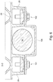
- FIG. 3 is a section through the deflecting element 100 along the line DD in FIG Fig. 2 shown.
- the deflecting element 100 and the channel element 44 can overlap as much as desired.
- the channel element 44 is in the simplified, schematic Fig. 6 not shown.
- the deflection element 100 is fastened to rails 25 and 26 of the underbody device 20 by means of screw connections 101 and 102, analogously to the channel element 41.
- the rails 25 and 26 are here C-rails, but can also be designed differently.
- the deflecting element 100 is fastened to the rails 25 and 26 or to other rails on the underbody device 20 with at least two further screw connections 101 and 102.
- the deflecting element 100 forms a rectangular shape that is open towards the electrical line 30.
- the rectangular shape is defined by two equal angles ⁇ , here 90 ° including one Tolerance range. However, the angles ⁇ can also be greater than 90 °.
- the deflecting element 100 then has a trapezoidal shape that is open towards the electrical line 30.
- the deflecting element 100 can also, analogously to the channel element 41, have a triangular shape or V shape that is open towards the electrical line 30. Alternatively, the deflecting element 100 can also have an arc shape open towards the electrical line 30, for example a circular arc shape.
- the electrical line 30 When assembling or equipping the vehicle 10, the electrical line 30 is clamped between the first V-shaped region 43 of the channel element 41 and the underbody device 20 by means of the fastening element 80 and the screw connections 82 and 83.
- the three-point receptacle enables the diameter fluctuations on the electrical line 30 to be compensated for within a tolerance range.
- the V-shaped area also causes stiffening of the channel element 41 and promotes drainage.
- the parallel sections 50 and 51 lead the electrical line 30 laterally.
- the inclined sections 52 and 53 enable the crimps 62 and 63, whereby the electrical line 30 is protected from damage by the edges 60 and 61.
- the inclined sections 52 and 53 also enable the electrical line 30 to be preassembled in the channel element 41. The electrical line 30 is prevented from falling out of the channel element 41 by a spring action of the inclined sections 52 and 53.
- the ends of the electrical line 30 can have a diameter that is greater than the diameter D of the electrical line 30.
- the dimensions of the channel element 41 depend on the diameter D of the electrical line 30. The ends of the electrical line 30 are therefore located outside the channel element 41.
- the drainage bore 92 serves to drain off water that can enter the channel element 41 during operation. Water can also be diverted from the deflection element 100 by means of drainage bores (not shown).
- the channel element 41 and the deflecting element 100 are grounded.
- the edge protection elements 91 serve to protect against injuries during assembly work and to protect end edges of the channel element 41 from damage.
- the second V-shaped region 81 of the fastening element 80 stiffens the first V-shaped region 43 of the channel element 41.
- the fastening element 80 is displaceable in the longitudinal direction x relative to the channel element 41 along the rails 23 and 24, depending on the installation conditions on the underbody device 20.
- the defined air gaps 84 ensure a secure tightening of the screw connections 82 and 83.
- the deflecting element 100 serves as protection against falling rocks for curved sections of the electrical line 30 in areas of bogies (not shown here).
- the channel device 40 meets the corresponding technical standards for rail vehicles.
- the channel element 41, the fastening element 80 and the deflecting element 100 manage with low wall thicknesses, as a result of which the respective associated weight is also low.
Landscapes
- Engineering & Computer Science (AREA)
- Mechanical Engineering (AREA)
- Architecture (AREA)
- Civil Engineering (AREA)
- Structural Engineering (AREA)
- Life Sciences & Earth Sciences (AREA)
- Wood Science & Technology (AREA)
- Installation Of Indoor Wiring (AREA)
- Details Of Indoor Wiring (AREA)
- Body Structure For Vehicles (AREA)
Claims (15)
- Véhicule (10) avec au moins un dispositif de canal (40),- dans lequel un unique conducteur (30) électrique est guidé, dans lequel- le véhicule (10) présente un dispositif sous-plancher (20) avec au moins une zone rectiligne (21) et au moins une zone de déviation (22) et- le dispositif de canal (40) comprend au moins un élément de canal (41) et au moins un élément de fixation (80), dans lequel- l'élément de canal (41) est fixé au moyen de l'élément de fixation (80) au niveau de la zone rectiligne (21) du dispositif sous-plancher (20),- l'élément de canal (41) est tenu à distance de la zone rectiligne (21) du dispositif sous-plancher (20), et
caractérisé en ce que- le conducteur (30) électrique dépasse radialement hors d'une zone d'ouverture (42) de l'élément de canal (41), et- une action de serrage est exercée sur le conducteur (30) électrique au moyen de l'élément de canal (41) et de l'élément de fixation (80). - Véhicule (10) selon la revendication 1, caractérisé en ce que l'élément de canal (41) réalise conjointement avec la zone rectiligne (21) du dispositif sous-plancher (20) un logement à trois points pour le conducteur (30) électrique.
- Véhicule (10) selon la revendication 2, caractérisé en ce que le conducteur (30) électrique repose au niveau d'un premier emplacement (71) et au niveau d'un deuxième emplacement (72) au niveau de l'élément de canal (41) et repose au niveau d'un troisième emplacement (73) au niveau de la zone rectiligne (21) du dispositif sous-plancher (20).
- Véhicule (10) selon l'une quelconque des revendications 1 à 3, caractérisé en ce que l'élément de canal (41) présente au moins une première zone en forme de V (43).
- Véhicule (10) selon la revendication 4, caractérisé en ce que l'élément de canal (41) présente deux sections (50, 51) parallèles, qui se raccordent à la première zone en forme de V (42).
- Véhicule (10) selon la revendication 5, caractérisé en ce que l'élément de canal (41) présente deux sections inclinées vers l'intérieur (52, 53), qui se raccordent aux sections parallèles (50, 51).
- Véhicule (10) selon la revendication 6, caractérisé en ce que la zone d'ouverture (42) est plus étroite qu'un diamètre (D) du conducteur (30) électrique.
- Véhicule (10) selon l'une quelconque des revendications précédentes, caractérisé en ce que des arêtes (60, 61) présentent respectivement un bord rabattu (62, 63) le long de la zone d'ouverture (42) de l'élément de canal (41), et/ou qu'au moins une extrémité (90) de l'élément de canal (41) présente au moins un élément de protection d'arête (91).
- Véhicule (10) selon l'une quelconque des revendications précédentes, caractérisé en ce que l'élément de canal (41) et l'élément de fixation (80) sont des composants séparés, et/ou qu'une longueur (I) de l'élément de canal (41) est plus grande qu'une largeur (b) de l'élément de canal (41).
- Véhicule (10) selon l'une quelconque des revendications 4 à 9, caractérisé en ce que l'élément de fixation (80) présente une deuxième zone en forme de V (81) et repose depuis l'extérieur au niveau de la première zone en forme de V (43) de l'élément de canal (41), et/ou que l'élément de fixation (80) peut être coulissé le long de l'élément de canal (41).
- Véhicule (10) selon l'une quelconque des revendications précédentes, caractérisé en ce que le dispositif de canal (40) comprend dans la zone de déviation (22) au moins un élément de déviation (100), qui entoure le conducteur (30) électrique conjointement avec la zone de déviation (22) et/ou recouvre au moins en partie l'élément de canal (41).
- Véhicule (10) selon la revendication 11, caractérisé en ce que l'élément de déviation (100) présente au moins un angle, de préférence deux angles de 90° (α) y compris respectivement d'une plage de tolérance, et est fixé au niveau de la zone de déviation (22).
- Véhicule (10) selon l'une quelconque des revendications précédentes, caractérisé en ce que le véhicule (10) est un véhicule sur rails.
- Procédé servant à équiper un véhicule (10) selon l'une quelconque des revendications 1 à 13 avec le dispositif de canal (40), caractérisé en ce que le conducteur (30) électrique est inséré dans au moins un élément de canal (41) puis l'élément de canal (41) est fixé au niveau du dispositif sous-plancher (20) au moyen de l'au moins un élément de fixation (80) dans au moins une zone rectiligne (21), dans lequel le conducteur (30) électrique est coincé entre l'élément de canal (41) et la zone rectiligne (21) du dispositif sous-plancher (20).
- Procédé selon la revendication 14, caractérisé en ce qu'après la fixation de l'élément de canal (41), l'au moins un élément de déviation (100) est fixé au niveau de l'au moins une zone de déviation (22) du dispositif sous-plancher (20).
Applications Claiming Priority (1)
| Application Number | Priority Date | Filing Date | Title |
|---|---|---|---|
| DE102017111525.0A DE102017111525A1 (de) | 2017-05-26 | 2017-05-26 | Fahrzeug mit mindestens einer Kanalvorrichtung und Verfahren zum Ausrüsten eines Fahrzeugs mit einer Kanalvorrichtung |
Publications (2)
| Publication Number | Publication Date |
|---|---|
| EP3406501A1 EP3406501A1 (fr) | 2018-11-28 |
| EP3406501B1 true EP3406501B1 (fr) | 2020-09-09 |
Family
ID=62186365
Family Applications (1)
| Application Number | Title | Priority Date | Filing Date |
|---|---|---|---|
| EP18172654.8A Active EP3406501B1 (fr) | 2017-05-26 | 2018-05-16 | Véhicule pourvu d'au moins un dispositif de canal et procédé permettant d'équiper un véhicule d'un dispositif de canal |
Country Status (3)
| Country | Link |
|---|---|
| EP (1) | EP3406501B1 (fr) |
| CN (1) | CN209079888U (fr) |
| DE (1) | DE102017111525A1 (fr) |
Families Citing this family (5)
| Publication number | Priority date | Publication date | Assignee | Title |
|---|---|---|---|---|
| DE102018113109A1 (de) * | 2018-06-01 | 2019-12-05 | Bombardier Transportation Gmbh | Schienenfahrzeug mit Kabelaufnahme |
| CN110571711A (zh) * | 2019-09-12 | 2019-12-13 | 江西洪都航空工业集团有限责任公司 | 一种适用于长距离封闭通道的电缆敷设导向装置 |
| US20210253176A1 (en) * | 2020-02-14 | 2021-08-19 | International Truck Intellectual Property Company, Llc | Method for assembling apparatus |
| FR3107241B1 (fr) * | 2020-02-18 | 2022-02-25 | Speedinnov | Voiture pour véhicule ferroviaire avec protection de câbles |
| US11865981B2 (en) * | 2020-05-05 | 2024-01-09 | Thor Tech, Inc. | Wire loom support |
Family Cites Families (6)
| Publication number | Priority date | Publication date | Assignee | Title |
|---|---|---|---|---|
| DE102005045604A1 (de) * | 2005-09-23 | 2007-03-29 | Siemens Ag | Doppelstock-Schienenfahrzeug mit zumindest einer Leitung |
| EP2322830A1 (fr) * | 2009-11-13 | 2011-05-18 | Zurecon Ag | Collier multifonctions |
| JP5393548B2 (ja) | 2010-03-16 | 2014-01-22 | 矢崎総業株式会社 | ワイヤハーネス |
| CN201758266U (zh) | 2010-07-15 | 2011-03-09 | 安徽省宁国诚信耐磨材料有限公司 | 一种风扇电线保护装置 |
| CN202260296U (zh) * | 2011-09-29 | 2012-05-30 | 唐山轨道客车有限责任公司 | 电线槽及铁路客车 |
| RU161654U1 (ru) | 2015-11-06 | 2016-04-27 | Олег Львович Пермяков | Устройство для крепления кабелей |
-
2017
- 2017-05-26 DE DE102017111525.0A patent/DE102017111525A1/de not_active Ceased
-
2018
- 2018-05-16 EP EP18172654.8A patent/EP3406501B1/fr active Active
- 2018-05-25 CN CN201820793099.9U patent/CN209079888U/zh not_active Expired - Fee Related
Non-Patent Citations (1)
| Title |
|---|
| None * |
Also Published As
| Publication number | Publication date |
|---|---|
| CN209079888U (zh) | 2019-07-09 |
| EP3406501A1 (fr) | 2018-11-28 |
| DE102017111525A1 (de) | 2019-01-03 |
Similar Documents
| Publication | Publication Date | Title |
|---|---|---|
| EP3406501B1 (fr) | Véhicule pourvu d'au moins un dispositif de canal et procédé permettant d'équiper un véhicule d'un dispositif de canal | |
| DE112012003947B4 (de) | Schelle | |
| DE4214508C2 (de) | Anordnung zur Masseanbindung an eine innere Blitzschutzanlage | |
| DE69902550T2 (de) | Langgestreckte tragstruktur mit hohlprofilträger mit einem querflansch an beiden endflächen | |
| EP3374234B1 (fr) | Système de fixation | |
| DE3712467A1 (de) | Koaxialkabel-uebertragungssystem | |
| DE1255761B (de) | Verbindungseinheit zur mechanischen und elektrischen Verbindung zweier starrer Verteilerkanaele | |
| EP2403084B1 (fr) | Guidage de câble et de conduite | |
| EP2565898B1 (fr) | Dispositif de commutation électrique | |
| EP3032154B1 (fr) | Ensemble de connexion avec un collier et un support pour la fixation d'une ligne, en particulier une ligne electrique, sur un vehicule ferroviaire | |
| EP3396799A1 (fr) | Dispositif de traversée | |
| DE102014116468B4 (de) | Befestigungselement und Kabelschacht | |
| EP4080069A1 (fr) | Système de fixation | |
| DE102008046658A1 (de) | Kabeldurchführung | |
| AT527805B1 (de) | Befestigung für ein Kabelführungsrohr | |
| EP3787924B1 (fr) | Ensemble de supports latéraux et installation de ligne aérienne | |
| DE102016225471B4 (de) | Handbremsseilvorrichtung | |
| DE102013015544A1 (de) | Leitungshalter und Befestigungsanordnung für zwei Leitungen an einem Karosserieteil | |
| DE102022004821B3 (de) | Kabelkanal | |
| DE4322232A1 (de) | Anordnung zum Verbinden eines Blitzschutzsystems mit einer Flugzeugstruktur | |
| WO2013182369A2 (fr) | Dispositif de fixation pour fixer un composant à un support | |
| DE102013211879A1 (de) | Fixieranordnung für ein Fahrzeug | |
| DE19816225A1 (de) | Hochbelastungshalterung, insbesondere für Wellrohre | |
| DE102016003692A1 (de) | Führungselement zum Führen wenigstens eines in einem Fahrzeug zu verbauenden Leitungselements, sowie Fahrzeug mit einem solchen Führungselement | |
| DE102005039652B4 (de) | Haltermodul zum Arretieren von Leitungen, Haltersystem zur geordneten Durchführung von Leitungen, Flugzeug und Verwendung einer Vielzahl von Haltermodulen |
Legal Events
| Date | Code | Title | Description |
|---|---|---|---|
| PUAI | Public reference made under article 153(3) epc to a published international application that has entered the european phase |
Free format text: ORIGINAL CODE: 0009012 |
|
| STAA | Information on the status of an ep patent application or granted ep patent |
Free format text: STATUS: THE APPLICATION HAS BEEN PUBLISHED |
|
| AK | Designated contracting states |
Kind code of ref document: A1 Designated state(s): AL AT BE BG CH CY CZ DE DK EE ES FI FR GB GR HR HU IE IS IT LI LT LU LV MC MK MT NL NO PL PT RO RS SE SI SK SM TR |
|
| AX | Request for extension of the european patent |
Extension state: BA ME |
|
| STAA | Information on the status of an ep patent application or granted ep patent |
Free format text: STATUS: REQUEST FOR EXAMINATION WAS MADE |
|
| 17P | Request for examination filed |
Effective date: 20190502 |
|
| RBV | Designated contracting states (corrected) |
Designated state(s): AL AT BE BG CH CY CZ DE DK EE ES FI FR GB GR HR HU IE IS IT LI LT LU LV MC MK MT NL NO PL PT RO RS SE SI SK SM TR |
|
| GRAP | Despatch of communication of intention to grant a patent |
Free format text: ORIGINAL CODE: EPIDOSNIGR1 |
|
| STAA | Information on the status of an ep patent application or granted ep patent |
Free format text: STATUS: GRANT OF PATENT IS INTENDED |
|
| INTG | Intention to grant announced |
Effective date: 20200402 |
|
| GRAS | Grant fee paid |
Free format text: ORIGINAL CODE: EPIDOSNIGR3 |
|
| GRAA | (expected) grant |
Free format text: ORIGINAL CODE: 0009210 |
|
| STAA | Information on the status of an ep patent application or granted ep patent |
Free format text: STATUS: THE PATENT HAS BEEN GRANTED |
|
| AK | Designated contracting states |
Kind code of ref document: B1 Designated state(s): AL AT BE BG CH CY CZ DE DK EE ES FI FR GB GR HR HU IE IS IT LI LT LU LV MC MK MT NL NO PL PT RO RS SE SI SK SM TR |
|
| REG | Reference to a national code |
Ref country code: GB Ref legal event code: FG4D Free format text: NOT ENGLISH |
|
| REG | Reference to a national code |
Ref country code: AT Ref legal event code: REF Ref document number: 1311238 Country of ref document: AT Kind code of ref document: T Effective date: 20200915 Ref country code: CH Ref legal event code: EP |
|
| REG | Reference to a national code |
Ref country code: CH Ref legal event code: NV Representative=s name: TR-IP CONSULTING LLC, CH Ref country code: IE Ref legal event code: FG4D Free format text: LANGUAGE OF EP DOCUMENT: GERMAN |
|
| REG | Reference to a national code |
Ref country code: DE Ref legal event code: R096 Ref document number: 502018002357 Country of ref document: DE |
|
| REG | Reference to a national code |
Ref country code: LT Ref legal event code: MG4D |
|
| PG25 | Lapsed in a contracting state [announced via postgrant information from national office to epo] |
Ref country code: SE Free format text: LAPSE BECAUSE OF FAILURE TO SUBMIT A TRANSLATION OF THE DESCRIPTION OR TO PAY THE FEE WITHIN THE PRESCRIBED TIME-LIMIT Effective date: 20200909 Ref country code: HR Free format text: LAPSE BECAUSE OF FAILURE TO SUBMIT A TRANSLATION OF THE DESCRIPTION OR TO PAY THE FEE WITHIN THE PRESCRIBED TIME-LIMIT Effective date: 20200909 Ref country code: NO Free format text: LAPSE BECAUSE OF FAILURE TO SUBMIT A TRANSLATION OF THE DESCRIPTION OR TO PAY THE FEE WITHIN THE PRESCRIBED TIME-LIMIT Effective date: 20201209 Ref country code: FI Free format text: LAPSE BECAUSE OF FAILURE TO SUBMIT A TRANSLATION OF THE DESCRIPTION OR TO PAY THE FEE WITHIN THE PRESCRIBED TIME-LIMIT Effective date: 20200909 Ref country code: GR Free format text: LAPSE BECAUSE OF FAILURE TO SUBMIT A TRANSLATION OF THE DESCRIPTION OR TO PAY THE FEE WITHIN THE PRESCRIBED TIME-LIMIT Effective date: 20201210 Ref country code: LT Free format text: LAPSE BECAUSE OF FAILURE TO SUBMIT A TRANSLATION OF THE DESCRIPTION OR TO PAY THE FEE WITHIN THE PRESCRIBED TIME-LIMIT Effective date: 20200909 Ref country code: BG Free format text: LAPSE BECAUSE OF FAILURE TO SUBMIT A TRANSLATION OF THE DESCRIPTION OR TO PAY THE FEE WITHIN THE PRESCRIBED TIME-LIMIT Effective date: 20201209 |
|
| REG | Reference to a national code |
Ref country code: NL Ref legal event code: MP Effective date: 20200909 |
|
| PG25 | Lapsed in a contracting state [announced via postgrant information from national office to epo] |
Ref country code: LV Free format text: LAPSE BECAUSE OF FAILURE TO SUBMIT A TRANSLATION OF THE DESCRIPTION OR TO PAY THE FEE WITHIN THE PRESCRIBED TIME-LIMIT Effective date: 20200909 Ref country code: PL Free format text: LAPSE BECAUSE OF FAILURE TO SUBMIT A TRANSLATION OF THE DESCRIPTION OR TO PAY THE FEE WITHIN THE PRESCRIBED TIME-LIMIT Effective date: 20200909 Ref country code: RS Free format text: LAPSE BECAUSE OF FAILURE TO SUBMIT A TRANSLATION OF THE DESCRIPTION OR TO PAY THE FEE WITHIN THE PRESCRIBED TIME-LIMIT Effective date: 20200909 |
|
| PG25 | Lapsed in a contracting state [announced via postgrant information from national office to epo] |
Ref country code: SM Free format text: LAPSE BECAUSE OF FAILURE TO SUBMIT A TRANSLATION OF THE DESCRIPTION OR TO PAY THE FEE WITHIN THE PRESCRIBED TIME-LIMIT Effective date: 20200909 Ref country code: PT Free format text: LAPSE BECAUSE OF FAILURE TO SUBMIT A TRANSLATION OF THE DESCRIPTION OR TO PAY THE FEE WITHIN THE PRESCRIBED TIME-LIMIT Effective date: 20210111 Ref country code: RO Free format text: LAPSE BECAUSE OF FAILURE TO SUBMIT A TRANSLATION OF THE DESCRIPTION OR TO PAY THE FEE WITHIN THE PRESCRIBED TIME-LIMIT Effective date: 20200909 Ref country code: CZ Free format text: LAPSE BECAUSE OF FAILURE TO SUBMIT A TRANSLATION OF THE DESCRIPTION OR TO PAY THE FEE WITHIN THE PRESCRIBED TIME-LIMIT Effective date: 20200909 Ref country code: EE Free format text: LAPSE BECAUSE OF FAILURE TO SUBMIT A TRANSLATION OF THE DESCRIPTION OR TO PAY THE FEE WITHIN THE PRESCRIBED TIME-LIMIT Effective date: 20200909 |
|
| PG25 | Lapsed in a contracting state [announced via postgrant information from national office to epo] |
Ref country code: ES Free format text: LAPSE BECAUSE OF FAILURE TO SUBMIT A TRANSLATION OF THE DESCRIPTION OR TO PAY THE FEE WITHIN THE PRESCRIBED TIME-LIMIT Effective date: 20200909 Ref country code: AL Free format text: LAPSE BECAUSE OF FAILURE TO SUBMIT A TRANSLATION OF THE DESCRIPTION OR TO PAY THE FEE WITHIN THE PRESCRIBED TIME-LIMIT Effective date: 20200909 Ref country code: IS Free format text: LAPSE BECAUSE OF FAILURE TO SUBMIT A TRANSLATION OF THE DESCRIPTION OR TO PAY THE FEE WITHIN THE PRESCRIBED TIME-LIMIT Effective date: 20210109 |
|
| REG | Reference to a national code |
Ref country code: DE Ref legal event code: R097 Ref document number: 502018002357 Country of ref document: DE |
|
| PG25 | Lapsed in a contracting state [announced via postgrant information from national office to epo] |
Ref country code: SK Free format text: LAPSE BECAUSE OF FAILURE TO SUBMIT A TRANSLATION OF THE DESCRIPTION OR TO PAY THE FEE WITHIN THE PRESCRIBED TIME-LIMIT Effective date: 20200909 |
|
| PLBE | No opposition filed within time limit |
Free format text: ORIGINAL CODE: 0009261 |
|
| STAA | Information on the status of an ep patent application or granted ep patent |
Free format text: STATUS: NO OPPOSITION FILED WITHIN TIME LIMIT |
|
| 26N | No opposition filed |
Effective date: 20210610 |
|
| PG25 | Lapsed in a contracting state [announced via postgrant information from national office to epo] |
Ref country code: SI Free format text: LAPSE BECAUSE OF FAILURE TO SUBMIT A TRANSLATION OF THE DESCRIPTION OR TO PAY THE FEE WITHIN THE PRESCRIBED TIME-LIMIT Effective date: 20200909 Ref country code: DK Free format text: LAPSE BECAUSE OF FAILURE TO SUBMIT A TRANSLATION OF THE DESCRIPTION OR TO PAY THE FEE WITHIN THE PRESCRIBED TIME-LIMIT Effective date: 20200909 |
|
| PG25 | Lapsed in a contracting state [announced via postgrant information from national office to epo] |
Ref country code: IT Free format text: LAPSE BECAUSE OF FAILURE TO SUBMIT A TRANSLATION OF THE DESCRIPTION OR TO PAY THE FEE WITHIN THE PRESCRIBED TIME-LIMIT Effective date: 20200909 |
|
| PG25 | Lapsed in a contracting state [announced via postgrant information from national office to epo] |
Ref country code: MC Free format text: LAPSE BECAUSE OF FAILURE TO SUBMIT A TRANSLATION OF THE DESCRIPTION OR TO PAY THE FEE WITHIN THE PRESCRIBED TIME-LIMIT Effective date: 20200909 Ref country code: LU Free format text: LAPSE BECAUSE OF NON-PAYMENT OF DUE FEES Effective date: 20210516 |
|
| REG | Reference to a national code |
Ref country code: BE Ref legal event code: MM Effective date: 20210531 |
|
| PG25 | Lapsed in a contracting state [announced via postgrant information from national office to epo] |
Ref country code: IE Free format text: LAPSE BECAUSE OF NON-PAYMENT OF DUE FEES Effective date: 20210516 |
|
| PG25 | Lapsed in a contracting state [announced via postgrant information from national office to epo] |
Ref country code: FR Free format text: LAPSE BECAUSE OF NON-PAYMENT OF DUE FEES Effective date: 20210531 |
|
| PG25 | Lapsed in a contracting state [announced via postgrant information from national office to epo] |
Ref country code: BE Free format text: LAPSE BECAUSE OF NON-PAYMENT OF DUE FEES Effective date: 20210531 |
|
| GBPC | Gb: european patent ceased through non-payment of renewal fee |
Effective date: 20220516 |
|
| PG25 | Lapsed in a contracting state [announced via postgrant information from national office to epo] |
Ref country code: GB Free format text: LAPSE BECAUSE OF NON-PAYMENT OF DUE FEES Effective date: 20220516 |
|
| PG25 | Lapsed in a contracting state [announced via postgrant information from national office to epo] |
Ref country code: NL Free format text: LAPSE BECAUSE OF NON-PAYMENT OF DUE FEES Effective date: 20200923 Ref country code: CY Free format text: LAPSE BECAUSE OF FAILURE TO SUBMIT A TRANSLATION OF THE DESCRIPTION OR TO PAY THE FEE WITHIN THE PRESCRIBED TIME-LIMIT Effective date: 20200909 |
|
| PG25 | Lapsed in a contracting state [announced via postgrant information from national office to epo] |
Ref country code: HU Free format text: LAPSE BECAUSE OF FAILURE TO SUBMIT A TRANSLATION OF THE DESCRIPTION OR TO PAY THE FEE WITHIN THE PRESCRIBED TIME-LIMIT; INVALID AB INITIO Effective date: 20180516 |
|
| P01 | Opt-out of the competence of the unified patent court (upc) registered |
Effective date: 20230822 |
|
| PG25 | Lapsed in a contracting state [announced via postgrant information from national office to epo] |
Ref country code: MK Free format text: LAPSE BECAUSE OF FAILURE TO SUBMIT A TRANSLATION OF THE DESCRIPTION OR TO PAY THE FEE WITHIN THE PRESCRIBED TIME-LIMIT Effective date: 20200909 |
|
| PG25 | Lapsed in a contracting state [announced via postgrant information from national office to epo] |
Ref country code: MT Free format text: LAPSE BECAUSE OF FAILURE TO SUBMIT A TRANSLATION OF THE DESCRIPTION OR TO PAY THE FEE WITHIN THE PRESCRIBED TIME-LIMIT Effective date: 20200909 |
|
| PGFP | Annual fee paid to national office [announced via postgrant information from national office to epo] |
Ref country code: DE Payment date: 20250521 Year of fee payment: 8 |
|
| PGFP | Annual fee paid to national office [announced via postgrant information from national office to epo] |
Ref country code: CH Payment date: 20250601 Year of fee payment: 8 |
|
| PGFP | Annual fee paid to national office [announced via postgrant information from national office to epo] |
Ref country code: AT Payment date: 20250522 Year of fee payment: 8 |
|
| PG25 | Lapsed in a contracting state [announced via postgrant information from national office to epo] |
Ref country code: TR Free format text: LAPSE BECAUSE OF FAILURE TO SUBMIT A TRANSLATION OF THE DESCRIPTION OR TO PAY THE FEE WITHIN THE PRESCRIBED TIME-LIMIT Effective date: 20200909 |