EP3240097A1 - Bloc-batterie - Google Patents
Bloc-batterie Download PDFInfo
- Publication number
- EP3240097A1 EP3240097A1 EP15872181.1A EP15872181A EP3240097A1 EP 3240097 A1 EP3240097 A1 EP 3240097A1 EP 15872181 A EP15872181 A EP 15872181A EP 3240097 A1 EP3240097 A1 EP 3240097A1
- Authority
- EP
- European Patent Office
- Prior art keywords
- temperature
- sub
- temperature sensor
- detected
- main
- Prior art date
- Legal status (The legal status is an assumption and is not a legal conclusion. Google has not performed a legal analysis and makes no representation as to the accuracy of the status listed.)
- Granted
Links
Images


Classifications
-
- H—ELECTRICITY
- H01—ELECTRIC ELEMENTS
- H01M—PROCESSES OR MEANS, e.g. BATTERIES, FOR THE DIRECT CONVERSION OF CHEMICAL ENERGY INTO ELECTRICAL ENERGY
- H01M10/00—Secondary cells; Manufacture thereof
- H01M10/42—Methods or arrangements for servicing or maintenance of secondary cells or secondary half-cells
- H01M10/48—Accumulators combined with arrangements for measuring, testing or indicating the condition of cells, e.g. the level or density of the electrolyte
-
- H—ELECTRICITY
- H02—GENERATION; CONVERSION OR DISTRIBUTION OF ELECTRIC POWER
- H02J—ELECTRIC POWER NETWORKS; CIRCUIT ARRANGEMENTS OR SYSTEMS FOR SUPPLYING OR DISTRIBUTING ELECTRIC POWER; SYSTEMS FOR STORING ELECTRIC ENERGY
- H02J7/00—Circuit arrangements for charging or discharging batteries or for supplying loads from batteries
- H02J7/02—Circuit arrangements for charging or discharging batteries or for supplying loads from batteries for charging batteries from AC mains by converters
- H02J7/04—Regulation of charging current or voltage
-
- Y—GENERAL TAGGING OF NEW TECHNOLOGICAL DEVELOPMENTS; GENERAL TAGGING OF CROSS-SECTIONAL TECHNOLOGIES SPANNING OVER SEVERAL SECTIONS OF THE IPC; TECHNICAL SUBJECTS COVERED BY FORMER USPC CROSS-REFERENCE ART COLLECTIONS [XRACs] AND DIGESTS
- Y02—TECHNOLOGIES OR APPLICATIONS FOR MITIGATION OR ADAPTATION AGAINST CLIMATE CHANGE
- Y02E—REDUCTION OF GREENHOUSE GAS [GHG] EMISSIONS, RELATED TO ENERGY GENERATION, TRANSMISSION OR DISTRIBUTION
- Y02E60/00—Enabling technologies; Technologies with a potential or indirect contribution to GHG emissions mitigation
- Y02E60/10—Energy storage using batteries
Definitions
- the present invention relates to a battery pack that detects a battery temperature by a temperature sensor, and in particular to a battery pack including a plurality of temperature sensors.
- a battery pack includes a temperature sensor that detects a battery temperature in order to charge and discharge a battery while protecting the battery.
- This battery pack detects a temperature of a battery, controls a charging/discharging current of the battery, or corrects charging/discharging efficiency varying depending on temperatures to accurately calculate the remaining capacity.
- This battery pack can protect the battery by cutting off the charging/discharging current when, for example, the temperature of the battery is higher than the highest temperature in a predetermined temperature range.
- the battery pack has a temperature terminal for outputting a signal of the detected temperature to a main body device to which the battery pack is set. To the temperature terminal, a temperature sensor such as a thermistor is connected. The temperature terminal outputs the temperature of the battery to the main body device.
- a temperature sensor is disposed in a region in which the temperature is the highest, and this temperature sensor is coupled to one temperature terminal.
- the detected battery temperature can be output to the main body device by a simple circuit-configuration.
- this battery pack can detect a temperature of a battery provided with a temperature sensor and output the detected temperature to the main body device, but it cannot detect a temperature of another battery and cannot output the temperature terminal to the main body device.
- all the battery temperatures cannot be equalized. Therefore, development of a battery pack incorporating a plurality of batteries, which includes a plurality of temperature sensors that detect a temperature of each battery, has been carried out (see Patent Literatures 1 and 2).
- a battery pack of Patent Literature 1 includes a plurality of temperature sensors disposed near a plurality of batteries and connected in series to a temperature terminal. This battery pack can output temperature signals of the plurality of temperature sensors from one temperature terminal.
- this battery pack detects a temperature from total serial resistance of all the temperature sensors connected in series, even when an electrical resistance value of a specific temperature sensor is changed, a change of the total serial resistance is small, this battery pack cannot accurately detect a change in the temperature of a battery.
- the change in the total serial resistance is reduced. Consequently, a detected temperature of each temperature sensor cannot be determined accurately.
- a battery pack of Patent Literature 2 is provided with a plurality of temperature sensors, and the temperature sensors are coupled to individual temperature terminals, respectively. Therefore, the number of temperature terminals is increased, and a circuit-configuration becomes complicated.
- a battery pack of PTL 3 includes a main temperature sensor and a sub temperature sensor.
- the main temperature sensor is coupled to a temperature terminal. Therefore, usually, a temperature signal of the main temperature sensor is output from the temperature terminal.
- this battery pack includes a temperature switch connected between the temperature terminal and an earth line. The temperature switch is controlled by detected temperatures of the sub temperature sensor and turned ON and OFF.
- This battery pack outputs a temperature signal of the main temperature sensor from the temperature terminal when the temperature switch is in an OFF state.
- a temperature monitoring circuit turns the temperature switch from an OFF state to an ON state, but when the temperature switch is turned to an ON state, the temperature terminal is short-circuited to the earth line, and an output impedance becomes substantially 0 ⁇ . Therefore, a main body device to which the battery pack is connected detects short-circuit of the temperature terminal, and can determine that the sub temperature sensor detects an abnormal temperature.
- the above-mentioned battery pack can output an ordinary normal temperature signal and an abnormal temperature signal from one temperature terminal.
- the sub temperature sensor detects an abnormal temperature
- the temperature terminal is short-circuited to the earth line. Therefore, when a voltage is applied to the temperature terminal for some reasons, a large short-circuit current flows. Furthermore, when the temperature terminal is short-circuited to the earth line, since the output impedance becomes substantially 0 ⁇ , an electric current value of the circuit for detecting an abnormal temperature becomes large.
- An important object of the present invention is to provide a battery pack capable of outputting a plurality of temperature signals from one temperature terminal with a simple circuit-configuration, and capable of outputting a plurality of temperature signals safely.
- a battery pack of the present invention includes a plurality of batteries 1; and includes main temperature sensor 2 that detects temperatures of batteries 1; temperature terminal 12 coupled to main temperature sensor 2; sub temperature sensor 3 that detects temperatures of battery packs 100 and 200, at a position different from that of main temperature sensor 2; main switch 4 connected between main temperature sensor 2 and temperature terminal 12, and, in an ON state, outputting a signal of main temperature sensor 2 to temperature terminal 12 and, in an OFF state, disconnecting main temperature sensor 2 from temperature terminal 12; and temperature monitoring circuit 5 that performs control so that main switch 4 is turned ON and OFF depending on a detected temperature of sub temperature sensor 3.
- Temperature monitoring circuit 5 compares the detected temperature detected by sub temperature sensor 3 with a predetermined temperature range, performs control so that main switch 4 is turned to an OFF state when the detected temperature is higher or lower than the predetermined temperature range, and outputs an abnormal signal from temperature terminal 12.
- the battery pack of the present invention includes resistor circuit 7 having a first end connected between temperature terminal 12 and main switch 4.
- Resistor circuit 7 includes sub-switch 8 and resistor 9.
- Resistor 9 has a resistance value out of a range of possible resistance values taken by main temperature sensor 2 depending on a temperature change. In an OFF state of main switch 4, temperature monitoring circuit 5 can turn sub-switch 8 of resistor circuit 7 to an ON state, and an output signal of temperature terminal 12 is the electrical resistance value of resistor 9.
- the battery pack of the present invention includes first resistor circuit 7A and second resistor circuit 7B having different electrical resistance values of resistors 9 and each having a sub-switch.
- temperature monitoring circuit 5 can turn sub-switch 8 of any one of first resistor circuit 7A and second resistor circuit 7B to an ON state, and an output signal of temperature terminal 12 can be the resistance value of resistor 9 of first or second resistor circuit that has been turned to an ON state.
- temperature monitoring circuit 5 compares the detected temperature of sub temperature sensor 3 with the predetermined temperature range, and turns main switch 4 to an OFF state when the detected temperature is higher than the predetermined temperature range and turns sub-switch 8 of first resistor circuit 7A to an ON state; turns main switch 4 to an OFF state when the detected temperature is lower than the predetermined temperature range and turns sub-switch 8 of first resistor circuit 7B to an ON state; and changes an output signal of temperature terminal 12, and outputs a signal from temperature terminal 12, indicating that the detected temperature of sub temperature sensor 3 is higher or lower than the predetermined temperature range.
- the battery pack of the present invention includes a plurality of sub temperature sensors 3. Temperature monitoring circuit 5 can compare a plurality of the detected temperatures detected by the plurality of sub temperature sensors 3 with the predetermined temperature range; perform control so that main switch 4 is turned to an OFF state when any one of the plurality of the detected temperatures is higher or lower than the predetermined temperature range, and output an abnormal signal from temperature terminal 12.
- the battery pack of the present invention includes a plurality of sub temperature sensors 3 and a plurality of resistor circuits 7.
- the plurality of resistor circuits 7 can include resistors 9 having different resistance values for each connected sub temperature sensor 3.
- temperature monitoring circuit 5 includes comparator 6, and comparator 6 can compare a detected voltage input from sub temperature sensor 3 with the reference voltage and compare the detected temperature with the predetermined temperature range.
- main temperature sensor 2 can detect a temperature of battery 1 having the highest temperature among the plurality of batteries 1 in a usual state
- sub temperature sensor 3 can detect a temperature of battery 1 that is distant from main temperature sensor 4.
- sub temperature sensor 3 can detect temperatures of circuit components.
- a battery pack of the present invention can safely output a plurality of temperature signals from one temperature terminal with a simple circuit-configuration. This is achieved because in the battery pack of the present invention, a temperature monitoring circuit compares a detected temperature of a sub temperature sensor with a predetermined temperature range, turns a main switch to an OFF state when the detected temperature is higher or lower than the predetermined temperature range, and outputs an abnormal signal from the temperature terminal.
- a battery pack of the present invention is detachably set to a portable device as a main body device, and supplies the main body device with supply power.
- the main body device to which a battery pack is set is a portable device such as a power tool.
- a main body device is not particularly limited to power tools and portable devices and may be any devices supplied with operation power from the battery pack.
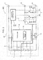
- Battery packs 100 and 200 shown in circuit diagrams of FIGs. 1 and 2 include a plurality of batteries 1 housed in outer case 10.
- Battery packs 100 and 200 include main temperature sensor 2 that detects a battery temperature inside outer case 10.
- battery packs 100 and 200 include positive and negative power terminals 11 connected to the output sides of batteries 1, and temperature terminal 12 coupled to main temperature sensor 2.
- Power terminals 11 and temperature terminal 12 are provided to outer case 10 so as to be connected to power supply contacts and a temperature detection contact at the main body device side when battery packs 100 and 200 are set to the main body device.
- Power terminals 11 and temperature terminal 12 are fixed to outer case 10 and exposed to the outside, or fixed to a circuit board disposed inside outer case 10 and exposed to the outside from electrode windows provided to outer case 10.
- charge-discharge switch 13 is connected between negative-side power terminal 11 and batteries 1.
- Charge-discharge switch 13 is a semiconductor switching element such as FET, and is turned ON and OFF by control of control circuit 14 including protective circuit 15 of batteries 1.
- Protective circuit 15 detects a voltage of each battery 1, and controls charge-discharge switch 13 such that voltages of all the batteries 1 are in a set range.
- Protective circuit 15 turns charge-discharge switch 13 to OFF when a voltage of the charged battery 1 exceeds the highest voltage, or when a voltage of the charged battery 1 is not more than the lowest voltage, thereby maintaining the voltage of battery 1 within a setting range to prevent battery 1 from being over-charged and over-discharged.
- Main temperature sensor 2 is a thermistor.
- the thermistor detects a temperature when temperature is increased by reduction of electrical resistance value.
- the thermistor detects a temperature accurately because a change value of the electrical resistance value is large with respect to the temperature change.
- any other elements whose temperature changes and an electrical resistance value is changed can be used.
- a varistor can be used.
- Main temperature sensor 2 is disposed on the surface of battery 1 whose temperature becomes the highest in a usual state of battery packs 100 and 200 and detects a temperature of battery 1 in a thermal bonding manner.
- Main temperature sensor 2 can be also disposed at a position in the vicinity of the surface of battery 1 and detect a temperature of battery 1.
- Temperature terminal 12 is connected to a temperature detection contact of a main body device, and transmits the temperature of battery 1 detected by main temperature sensor 2 to the main body device.
- the main body device controls a charge-discharge electric current based on the temperature of battery 1 transmitted from temperature terminal 12 of battery packs 100 and 200 and protects batteries 1.
- Main temperature sensor 2 continues to carry out temperature detection and output of the detected temperature to temperature terminal 12 because temperatures of batteries 1 are necessary for charge-discharge control.
- Battery packs 100 and 200 of FIGs. 1 and 2 include sub temperature sensor 3, in addition to main temperature sensor 2, inside outer case 10.
- Sub temperature sensor 3 is a temperature detector such as a thermistor similar to main temperature sensor 2.
- Sub temperature sensor 3 is disposed at a position different from that of main temperature sensor 2, and detects a temperature of battery 1 that is different from battery 1 whose temperature is detected by main temperature sensor 2, or detects a different portion in outer case 10.
- Sub temperature sensor 3 detects a temperature of battery 1 disposed at a position distant from main temperature sensor 2, or sub temperature sensor 3 is disposed at a position in which the temperature is likely to increase and detects a temperature inside outer case 10.
- Sub temperature sensor 3 is not directly coupled to temperature terminal 12.
- main switch 4 that is turned ON and OFF depending on sub temperature sensor 3 is connected between main temperature sensor 2 and temperature terminal 12.
- Main switch 4 is turned ON and OFF depending on detected temperatures of sub temperature sensor 3.
- temperature monitoring circuit 5 for switching main switch 4 ON and OFF depending on the detected temperatures of sub temperature sensor 3 is provided.
- Temperature monitoring circuit 5 includes a comparator for determining whether the detected temperature of sub temperature sensor 3 exceeds the upper threshold in the predetermined temperature range (for example, 0 to 80°C). Temperature monitoring circuit 5A of battery pack 100 shown in FIG. 1 compares the detected temperature of sub temperature sensor 3 with the upper threshold using the comparator. When the detected temperature becomes higher than the upper threshold, temperature monitoring circuit 5A determines that a state is in an abnormal temperature state, and turns main switch 4 OFF. The upper threshold with which the detected temperature is compared is set at an optimum temperature in the range of, for example, 70°C or more and 80°C or less. In sub temperature sensor 3, an electrical resistance value is changed depending on temperatures. Therefore, the comparator of temperature monitoring circuit 5A compares a voltage value varying depending on the electrical resistance value of sub temperature sensor 3 with the upper threshold, and determines whether the detected temperature is higher than the upper threshold.
- the comparator of temperature monitoring circuit 5A compares a voltage value varying depending on the electrical resistance value of sub temperature sensor 3 with the upper threshold, and determine
- FIG. 3 shows a specific circuit diagram of temperature monitoring circuit 5A including comparator 6.
- Comparator 6 includes one input-side to which a reference voltage is input, and the other input-side to which a detected voltage varying depending on the detected temperatures of sub temperature sensor 3 is input. Comparator 6 compares the detected voltage with the reference voltage and detects that the detected temperature is higher than the upper threshold.
- comparator 6 of temperature monitoring circuit 5A of FIG. 3 a reference voltage is input to a negative-side input terminal, and a positive-side power line is connected to a positive-side input terminal via sub temperature sensor 3. Furthermore, input resistor 16 is connected between the positive-side input terminal and the negative-side earth line. That is to say, in temperature monitoring circuit 5A of FIG. 3 , a series circuit of sub temperature sensor 3 and input resistor 16 is connected between the positive-side power line and the negative-side earth line, and connection point 17 between sub temperature sensor 3 and input resistor 16 is input to the positive-side input terminal of comparator 6.
- the reference voltage of comparator 6 is a voltage that is input when the detection temperature of sub temperature sensor 3 is the upper threshold, for example, for example, 80°C.
- the detected temperature of sub temperature sensor 3 is lower than 80°C as the upper threshold, since the input detected voltage is lower than the reference voltage, comparator 6 outputs "Low.”
- comparator 6 outputs "High.” Therefore, when comparator 6 determines that the detected temperature is higher than the upper threshold and in an abnormal temperature state, comparator 6 outputs an abnormal signal "High,” and turns main switch 4 OFF.
- Temperature monitoring circuit 5A mentioned above can compare the detected temperature with the upper threshold in real time. Temperature monitoring circuit 5 can also compare a digital signal, which is obtained by converting an electrical resistance value detected by sub temperature sensor 3 or an analog signal converted from the electrical resistance value into a voltage value, with the stored upper threshold, and determine whether or not the detected temperature is higher than the upper threshold.
- temperature monitoring circuit 5A turns main switch 4 to an OFF state. In this state, main temperature sensor 2 is not coupled to temperature terminal 12, and the output impedance of temperature terminal 12 is higher than the electrical resistance value of main temperature sensor 2. On the other hand, when the detected temperature is not higher than upper threshold, since main switch 4 is kept in an ON state, main temperature sensor 2 is coupled to temperature terminal 12, and a signal of main temperature sensor 2 is transmitted from temperature terminal 12 to the main body device.
- Battery pack 100 of FIG. 1 determines that a state in which the detected temperature of sub temperature sensor 3 is higher than the upper threshold of the predetermined temperature range is an abnormal temperature state and turns main switch 4 to an OFF state. Therefore, sub temperature sensor 3 can detect that the battery temperature is increased to an abnormal temperature, and the detected state is transmitted from temperature terminal 12 to main body device.
- the battery pack of the present invention can also determine that a state in which the detected temperature is lower than a lower threshold of the predetermined temperature range, which has been set at, for example, 0°C to 5°C, is an abnormal temperature state and turn main switch 4 to an OFF state. This battery pack transmits a state in which the battery temperature is abnormally low as an abnormal temperature state to the main body device.
- temperature monitoring circuit 5B of FIG. 2 includes comparator 6 that determines whether the detected temperature of sub temperature sensor 3 is higher or lower than the predetermined temperature range.
- Temperature monitoring circuit 5B of this drawing includes first comparator 6A that compares the detected temperature with the upper threshold of the predetermined temperature range, and second comparator 6B that compares the detected temperature with the lower threshold of the predetermined temperature range.
- First comparator 6A sets the upper threshold to be compared with the detected temperature at, for example, 70°C to 80°C, and determines that a state in which the detected temperature of sub temperature sensor 3 is higher than the upper threshold is an abnormal temperature state and outputs an abnormal signal.
- Second comparator 6B sets the lower threshold to be compared with the detected temperature at, for example, 0°C to 5°C, and determines that a state in which the detected temperature of sub temperature sensor 3 is lower than the lower threshold is an abnormal temperature state and outputs an abnormal signal.
- FIG. 4 shows temperature monitoring circuit 5B including two comparators 6.
- Comparator 6 of this drawing is a differential amplifier in which a reference voltage is input into one input-side. In comparator 6, the detected voltage varying depending on the detected temperature of sub temperature sensor 3 is input to the other input-side. Comparator 6 compares the detected voltage with the reference voltage, turns the output into "Low” and "High,” and outputs an abnormal signal.
- a series circuit of sub temperature sensor 3 and input resistor 16 which are connected in series each other, is connected between the positive-side power line and the negative-side earth line. Connection point 17 between sub temperature sensor 3 and input resistor 16 is connected to the other input-side of comparator 6, and the detected voltage varying depending on the detected temperature of sub temperature sensor 3 is input into comparator 6.
- first comparator 6A a reference voltage is input to the negative-side input terminal, and connection point 17 between sub temperature sensor 3 and input resistor 16 is connected and a detected voltage is input to the positive-side input terminal.
- the reference voltage of first comparator 6A is a voltage that is input when the detection temperature of sub temperature sensor 3 is the upper threshold, for example, 80°C.
- first comparator 6A When the detected temperature of sub temperature sensor 3 is lower than 80°C as the upper threshold, since the input detected voltage is lower than the reference voltage, first comparator 6A outputs "Low.” When the detected temperature is higher than 80°C, since the input detected voltage is higher than the reference voltage, first comparator 6A outputs "High.” Therefore, when first comparator 6A outputs an abnormal signal "High” and turns main switch 4 OFF.
- second comparator 6B to the positive-side input terminal, a reference voltage is input, and to the negative-side input terminal, connection point 17 between sub temperature sensor 3 and input resistor 16 is connected and the detected voltage is input.
- the reference voltage of second comparator 6B is a voltage that is input when the detection temperature of sub temperature sensor 3 is the lower threshold, for example, 0°C.
- second comparator 6B When the detected temperature of sub temperature sensor 3 is higher than 0°C as the lower threshold, since the input detected voltage is higher than the reference voltage, second comparator 6B outputs "Low.” When the detected temperature is lower than 0°C, the input detected voltage is lower than the reference voltage, and second comparator 6B outputs "High.” Therefore, when second comparator 6B outputs an abnormal signal "High” and turns main switch 4 OFF.
- Temperature monitoring circuit 5B mentioned above also can compare the detected temperature with the threshold in the predetermined temperature range in real time. Temperature monitoring circuit 5 can also compare a digital signal, which is obtained by converting an electrical resistance value detected by sub temperature sensor 3 or an analog signal converted from the electrical resistance value into a voltage value, with the stored upper threshold, and determine whether or not the detected temperature is higher than the upper threshold, or the detected temperature is lower than the lower threshold.
- Temperature monitoring circuit 5B compares the detected temperature of sub temperature sensor 3 with the threshold, outputs an abnormal signal when the detected temperature exceeds the threshold in the predetermined temperature range, turns main switch 4 from ON to OFF, and disconnects main temperature sensor 2 from temperature terminal 12. Therefore, when the detected temperature of sub temperature sensor 3 is higher than the upper threshold, or lower than the lower threshold, that is, when the detected temperature exceeds the predetermined temperature range, a temperature signal of main temperature sensor 2 is not output to temperature terminal 12.
- main switch 4 is in an OFF state, and output impedance of temperature terminal 12 is changed, a main body device determines that the detected temperature of sub temperature sensor 3 exceeds the threshold of the predetermined temperature range.
- Battery pack 200 of FIG. 2 includes resistor circuit 7 controlled by temperature monitoring circuit 5B so that an output impedance of temperature terminal 12 is a specific electrical resistance value when the detected temperature of sub temperature sensor 3 exceeds the threshold of a predetermined temperature range.
- Resistor circuit 7 is a series circuit of sub-switch 8 and resistor 9. A first end of resistor circuit 7 is connected between temperature terminal 12 and main switch 4. A second end of resistor circuit 7 shown in FIG. 2 is connected to one of power terminals 11 (negative-side power terminal in the drawing). That is to say, resistor circuit 7 is connected between temperature terminal 12 and one of the power terminals 11.
- Sub-switch 8 of resistor circuit 7 is turned ON in an OFF state of main switch 4, and the output impedance of temperature terminal 12 is an electrical resistance value of resistor 9.
- Battery pack 200 shown in FIGs. 2 and 4 includes two resistor circuits 7 controlled by two comparators 6 of temperature monitoring circuit 5B.
- Resistors 9 of two resistor circuits 7 have different electrical resistance values from that of main temperature sensor 2.
- the electrical resistance value of resistor 9 is a resistance value out of the range of possible electrical resistance values taken by main temperature sensor 2 depending on a temperature change. That is to say, the electrical resistance value of resistor 9 is set to smaller than the minimum electrical resistance value or larger than the maximum electrical resistance value of the values, varying within the predetermined temperature range, of main temperature sensor 2.
- Sub-switch 8 of resistor circuit 7 is controlled by temperature monitoring circuit 5B.
- temperature monitoring circuit 5B turns main switch 4 OFF and turns one of sub-switches 8 ON, and an output impedance of temperature terminal 12 is an electrical resistance value of resistor 9 of resistor circuit 7 which has been turned to an ON state.
- first resistor circuit 7A and second resistor circuit 7B having different electrical resistance values of resistors 9, are connected in parallel.
- First and second resistor circuits 7A and 7B are coupled to temperature terminal 12 and one of power terminals 11.
- First comparator 6A performs control so that first sub-switch 8A of first resistor circuit 7A is turned ON and OFF; and second comparator 6B performs control so that second sub-switch 8B of second resistor circuit 7B is turned ON and OFF.
- first resistor 9A of first resistor circuit 7A and second resistor 9B of second resistor circuit 7B are resistance values out of the range of possible electrical resistance values taken by main temperature sensor 2 by a temperature change. Electrical resistances of first resistor 9A and second resistor 9B are different values. For example, the electrical resistance value of first resistor 9A is set at a larger value than the varying maximum electrical resistance value of main temperature sensor 2, and the electrical resistance value of second resistor 9B is set at a smaller value than the varying minimum electrical resistance values of main temperature sensor 2.
- First comparator 6A of temperature monitoring circuit 5B compares the detected temperature of sub temperature sensor 3 with the upper threshold in the predetermined temperature range, and when the detected temperature is higher than the upper threshold, outputs an abnormal signal and turns main switch 4 to an OFF state and first sub-switch 8A to an ON state. In this state, the output impedance of temperature terminal 12 is an electrical resistance value of first resistor 9A.
- Second comparator 6B of temperature monitoring circuit 5B compares the detected temperature of sub temperature sensor 3 with the lower threshold in the predetermined temperature range, and when the detected temperature is lower than the lower threshold, outputs an abnormal signal and turns main switch 4 to an OFF state and second sub-switch 8B to an ON state. In this state, the output impedance of temperature terminal 12 is an electrical resistance value of second resistor 9B.
- the main body device determines that the detected temperature of sub temperature sensor 3 is higher than the upper threshold when the output impedance of temperature terminal 12 is an electrical resistance value of first resistor 9A, and determines that the detected temperature of sub temperature sensor 3 is lower than the lower threshold when the output impedance of temperature terminal 12 is an electrical resistance value of second resistor 9B.
- temperature monitoring circuit 5B turns sub-switches 8 of two resistor circuits 7 ON and OFF to change the output impedance of temperature terminal 12, and transmits an abnormal temperature state to the main body device.
- the battery pack may be provided with three or more resistor circuits, perform control so that a sub-switch of each of the resistor circuits is tuned ON and OFF, and transmit three or more abnormal signals to the main body device.
- This battery pack has three or more thresholds for comparing the detected temperature of sub temperature sensor, and can transmit signals to main body device, indicating that any of the detected temperatures exceeds the threshold.
- the battery pack can set, for example, a lower threshold at 0°C, a high-temperature threshold at 70°C, an upper threshold at 80°C, and transmit any one of the abnormal temperature states, that is, the detected temperature of sub temperature sensor 3 of 0°C or less, 70°C or more, and 80°C or more, to the main body device.
- sub temperature sensor 3 detects a temperature of battery 1 that is other than battery 1 whose temperature is detected by main temperature sensor 2, but may detect temperatures of circuit components such as charge-discharge switch 13 and protective circuit 15 mounted on the circuit board. At this time, by comparing the detected temperature of sub temperature sensor 3 with the threshold in the predetermined temperature range corresponding to the circuit components, an abnormal temperature state of the circuit components can be transmitted to a main body device.
- temperature monitoring circuit 5 can compare a plurality of detected temperatures detected by the plurality of sub temperature sensors 3 with the predetermined temperature range, perform control so that main switch 4 is turned OFF when any one of the plurality of detected temperatures is higher or lower than the predetermined temperature range, and can transmit an abnormal signal from temperature terminal 12 to the main body device.
- one sub temperature sensor 3 is disposed, but a plurality of sub temperature sensors 3 may be disposed.
- one to a plurality of resistor circuits 7 can be disposed corresponding to each of the plurality of sub temperature sensors 3.
- These resistor circuits 7 are disposed between temperature terminal 12 and main switch 4 at a first end, and connected to one of power terminals 11 at a second end. At this time, when the electrical resistance values of resistor 9 of resistor circuit 7 are different values for each sub temperature sensor 3, any one of the sub temperature sensors 3 can transmit an abnormal temperature state to the main body device.
- the present invention can be safely used for a battery pack by transmitting an abnormal temperature to a main body device with a simple circuit structure.
Landscapes
- Engineering & Computer Science (AREA)
- Manufacturing & Machinery (AREA)
- Chemical & Material Sciences (AREA)
- Chemical Kinetics & Catalysis (AREA)
- Electrochemistry (AREA)
- General Chemical & Material Sciences (AREA)
- Power Engineering (AREA)
- Secondary Cells (AREA)
- Battery Mounting, Suspending (AREA)
- Charge And Discharge Circuits For Batteries Or The Like (AREA)
Applications Claiming Priority (2)
| Application Number | Priority Date | Filing Date | Title |
|---|---|---|---|
| JP2014262576A JP2018029407A (ja) | 2014-12-25 | 2014-12-25 | 電池パック |
| PCT/JP2015/006128 WO2016103606A1 (fr) | 2014-12-25 | 2015-12-09 | Bloc-batterie |
Publications (3)
| Publication Number | Publication Date |
|---|---|
| EP3240097A4 EP3240097A4 (fr) | 2017-11-01 |
| EP3240097A1 true EP3240097A1 (fr) | 2017-11-01 |
| EP3240097B1 EP3240097B1 (fr) | 2018-08-01 |
Family
ID=56149675
Family Applications (1)
| Application Number | Title | Priority Date | Filing Date |
|---|---|---|---|
| EP15872181.1A Not-in-force EP3240097B1 (fr) | 2014-12-25 | 2015-12-09 | Bloc-batterie |
Country Status (3)
| Country | Link |
|---|---|
| EP (1) | EP3240097B1 (fr) |
| JP (1) | JP2018029407A (fr) |
| WO (1) | WO2016103606A1 (fr) |
Cited By (1)
| Publication number | Priority date | Publication date | Assignee | Title |
|---|---|---|---|---|
| US11955615B2 (en) | 2019-06-17 | 2024-04-09 | Makita Corporation | Battery-powered portable tool |
Families Citing this family (5)
| Publication number | Priority date | Publication date | Assignee | Title |
|---|---|---|---|---|
| CN110907056A (zh) * | 2018-09-14 | 2020-03-24 | 宁德时代新能源科技股份有限公司 | 一种电池组温度检测系统 |
| CN120300966A (zh) * | 2019-06-12 | 2025-07-11 | 苏州宝时得电动工具有限公司 | 一种电池包 |
| JP7323800B2 (ja) * | 2019-10-18 | 2023-08-09 | ミツミ電機株式会社 | 二次電池保護回路、二次電池保護装置、電池パック及び温度検出回路 |
| TWM593074U (zh) * | 2019-11-11 | 2020-04-01 | 鑽全實業股份有限公司 | 電池裝置及電池裝置充電系統 |
| CN118507885B (zh) * | 2024-04-17 | 2025-07-15 | 惠州市乐亿通科技股份有限公司 | 锂电池温度监测系统及方法 |
Family Cites Families (7)
| Publication number | Priority date | Publication date | Assignee | Title |
|---|---|---|---|---|
| JP4278622B2 (ja) * | 2004-03-18 | 2009-06-17 | 三洋電機株式会社 | 電源装置 |
| JP4931378B2 (ja) * | 2005-07-06 | 2012-05-16 | 三洋電機株式会社 | 車両用の電源装置 |
| JP5098501B2 (ja) * | 2007-08-07 | 2012-12-12 | ミツミ電機株式会社 | 電池パック |
| JP5219463B2 (ja) * | 2007-11-08 | 2013-06-26 | 三洋電機株式会社 | パック電池 |
| JP2012501061A (ja) * | 2008-08-28 | 2012-01-12 | ローベルト ボツシユ ゲゼルシヤフト ミツト ベシユレンクテル ハフツング | 蓄電池パック |
| EP2528189B1 (fr) * | 2010-01-22 | 2018-11-28 | Toyota Jidosha Kabushiki Kaisha | Système de gestion de charge de batterie |
| WO2014141809A1 (fr) * | 2013-03-13 | 2014-09-18 | Necエナジーデバイス株式会社 | Bloc de batterie, corps mobile et procédé de commande |
-
2014
- 2014-12-25 JP JP2014262576A patent/JP2018029407A/ja active Pending
-
2015
- 2015-12-09 WO PCT/JP2015/006128 patent/WO2016103606A1/fr not_active Ceased
- 2015-12-09 EP EP15872181.1A patent/EP3240097B1/fr not_active Not-in-force
Cited By (1)
| Publication number | Priority date | Publication date | Assignee | Title |
|---|---|---|---|---|
| US11955615B2 (en) | 2019-06-17 | 2024-04-09 | Makita Corporation | Battery-powered portable tool |
Also Published As
| Publication number | Publication date |
|---|---|
| EP3240097A4 (fr) | 2017-11-01 |
| WO2016103606A1 (fr) | 2016-06-30 |
| JP2018029407A (ja) | 2018-02-22 |
| EP3240097B1 (fr) | 2018-08-01 |
Similar Documents
| Publication | Publication Date | Title |
|---|---|---|
| EP3240097B1 (fr) | Bloc-batterie | |
| KR101973054B1 (ko) | 배터리 팩 및 배터리 팩의 제어 방법 | |
| TWI425737B (zh) | 充電裝置及充電方法 | |
| JP3848574B2 (ja) | 充放電制御装置 | |
| KR101084211B1 (ko) | 배터리 팩, 및 배터리 팩의 충전 제어 방법 | |
| US8489347B2 (en) | Battery pack monitoring apparatus | |
| CN106169782B (zh) | 电池保护集成电路、电池保护装置以及电池组 | |
| KR101440888B1 (ko) | 배터리 보호 회로 | |
| USRE50397E1 (en) | Battery pack | |
| US8659265B2 (en) | Battery pack and method of sensing voltage of battery pack | |
| EP2416469A1 (fr) | Dispositif de charge | |
| JP4911430B2 (ja) | 充電装置 | |
| WO2018054143A1 (fr) | Batterie, terminal, et système de charge | |
| CN102576057A (zh) | 过电流检测电路及电池组件 | |
| EP2911267A1 (fr) | Système de gestion de batterie | |
| JP6370137B2 (ja) | 充放電制御回路及びバッテリ装置 | |
| EP2592427A1 (fr) | Circuit et procédé de mesure de tension électrique | |
| JP2015223008A (ja) | 電源装置及びこの電源装置を備える電動車両並びに蓄電装置 | |
| EP2365602B1 (fr) | Chargeur de bloc-batteries | |
| EP3109927B1 (fr) | Combinaison électrique | |
| KR102291537B1 (ko) | Csr 지원 ic 소자 공용화를 위한 배터리 보호회로 | |
| KR20110057513A (ko) | 배터리 팩 | |
| CN101842958A (zh) | 用来给至少一个可重复充电的能量储存器进行充电的充电器 | |
| KR102320110B1 (ko) | 하나의 전류 센싱 저항을 갖는 배터리 보호 회로 | |
| JP4907113B2 (ja) | 2次電池の充電システム装置 |
Legal Events
| Date | Code | Title | Description |
|---|---|---|---|
| PUAI | Public reference made under article 153(3) epc to a published international application that has entered the european phase |
Free format text: ORIGINAL CODE: 0009012 |
|
| 17P | Request for examination filed |
Effective date: 20170613 |
|
| A4 | Supplementary search report drawn up and despatched |
Effective date: 20170913 |
|
| AK | Designated contracting states |
Kind code of ref document: A1 Designated state(s): AL AT BE BG CH CY CZ DE DK EE ES FI FR GB GR HR HU IE IS IT LI LT LU LV MC MK MT NL NO PL PT RO RS SE SI SK SM TR |
|
| AX | Request for extension of the european patent |
Extension state: BA ME |
|
| GRAP | Despatch of communication of intention to grant a patent |
Free format text: ORIGINAL CODE: EPIDOSNIGR1 |
|
| DAV | Request for validation of the european patent (deleted) | ||
| DAX | Request for extension of the european patent (deleted) | ||
| INTG | Intention to grant announced |
Effective date: 20180216 |
|
| GRAS | Grant fee paid |
Free format text: ORIGINAL CODE: EPIDOSNIGR3 |
|
| GRAA | (expected) grant |
Free format text: ORIGINAL CODE: 0009210 |
|
| AK | Designated contracting states |
Kind code of ref document: B1 Designated state(s): AL AT BE BG CH CY CZ DE DK EE ES FI FR GB GR HR HU IE IS IT LI LT LU LV MC MK MT NL NO PL PT RO RS SE SI SK SM TR |
|
| REG | Reference to a national code |
Ref country code: GB Ref legal event code: FG4D |
|
| REG | Reference to a national code |
Ref country code: CH Ref legal event code: EP Ref country code: AT Ref legal event code: REF Ref document number: 1025411 Country of ref document: AT Kind code of ref document: T Effective date: 20180815 |
|
| REG | Reference to a national code |
Ref country code: IE Ref legal event code: FG4D |
|
| REG | Reference to a national code |
Ref country code: DE Ref legal event code: R096 Ref document number: 602015014473 Country of ref document: DE |
|
| REG | Reference to a national code |
Ref country code: NL Ref legal event code: MP Effective date: 20180801 |
|
| REG | Reference to a national code |
Ref country code: LT Ref legal event code: MG4D |
|
| REG | Reference to a national code |
Ref country code: AT Ref legal event code: MK05 Ref document number: 1025411 Country of ref document: AT Kind code of ref document: T Effective date: 20180801 |
|
| PG25 | Lapsed in a contracting state [announced via postgrant information from national office to epo] |
Ref country code: NO Free format text: LAPSE BECAUSE OF FAILURE TO SUBMIT A TRANSLATION OF THE DESCRIPTION OR TO PAY THE FEE WITHIN THE PRESCRIBED TIME-LIMIT Effective date: 20181101 Ref country code: GR Free format text: LAPSE BECAUSE OF FAILURE TO SUBMIT A TRANSLATION OF THE DESCRIPTION OR TO PAY THE FEE WITHIN THE PRESCRIBED TIME-LIMIT Effective date: 20181102 Ref country code: PL Free format text: LAPSE BECAUSE OF FAILURE TO SUBMIT A TRANSLATION OF THE DESCRIPTION OR TO PAY THE FEE WITHIN THE PRESCRIBED TIME-LIMIT Effective date: 20180801 Ref country code: SE Free format text: LAPSE BECAUSE OF FAILURE TO SUBMIT A TRANSLATION OF THE DESCRIPTION OR TO PAY THE FEE WITHIN THE PRESCRIBED TIME-LIMIT Effective date: 20180801 Ref country code: FI Free format text: LAPSE BECAUSE OF FAILURE TO SUBMIT A TRANSLATION OF THE DESCRIPTION OR TO PAY THE FEE WITHIN THE PRESCRIBED TIME-LIMIT Effective date: 20180801 Ref country code: LT Free format text: LAPSE BECAUSE OF FAILURE TO SUBMIT A TRANSLATION OF THE DESCRIPTION OR TO PAY THE FEE WITHIN THE PRESCRIBED TIME-LIMIT Effective date: 20180801 Ref country code: RS Free format text: LAPSE BECAUSE OF FAILURE TO SUBMIT A TRANSLATION OF THE DESCRIPTION OR TO PAY THE FEE WITHIN THE PRESCRIBED TIME-LIMIT Effective date: 20180801 Ref country code: AT Free format text: LAPSE BECAUSE OF FAILURE TO SUBMIT A TRANSLATION OF THE DESCRIPTION OR TO PAY THE FEE WITHIN THE PRESCRIBED TIME-LIMIT Effective date: 20180801 Ref country code: IS Free format text: LAPSE BECAUSE OF FAILURE TO SUBMIT A TRANSLATION OF THE DESCRIPTION OR TO PAY THE FEE WITHIN THE PRESCRIBED TIME-LIMIT Effective date: 20181201 Ref country code: NL Free format text: LAPSE BECAUSE OF FAILURE TO SUBMIT A TRANSLATION OF THE DESCRIPTION OR TO PAY THE FEE WITHIN THE PRESCRIBED TIME-LIMIT Effective date: 20180801 Ref country code: BG Free format text: LAPSE BECAUSE OF FAILURE TO SUBMIT A TRANSLATION OF THE DESCRIPTION OR TO PAY THE FEE WITHIN THE PRESCRIBED TIME-LIMIT Effective date: 20181101 |
|
| PG25 | Lapsed in a contracting state [announced via postgrant information from national office to epo] |
Ref country code: AL Free format text: LAPSE BECAUSE OF FAILURE TO SUBMIT A TRANSLATION OF THE DESCRIPTION OR TO PAY THE FEE WITHIN THE PRESCRIBED TIME-LIMIT Effective date: 20180801 Ref country code: LV Free format text: LAPSE BECAUSE OF FAILURE TO SUBMIT A TRANSLATION OF THE DESCRIPTION OR TO PAY THE FEE WITHIN THE PRESCRIBED TIME-LIMIT Effective date: 20180801 Ref country code: HR Free format text: LAPSE BECAUSE OF FAILURE TO SUBMIT A TRANSLATION OF THE DESCRIPTION OR TO PAY THE FEE WITHIN THE PRESCRIBED TIME-LIMIT Effective date: 20180801 |
|
| PG25 | Lapsed in a contracting state [announced via postgrant information from national office to epo] |
Ref country code: EE Free format text: LAPSE BECAUSE OF FAILURE TO SUBMIT A TRANSLATION OF THE DESCRIPTION OR TO PAY THE FEE WITHIN THE PRESCRIBED TIME-LIMIT Effective date: 20180801 Ref country code: IT Free format text: LAPSE BECAUSE OF FAILURE TO SUBMIT A TRANSLATION OF THE DESCRIPTION OR TO PAY THE FEE WITHIN THE PRESCRIBED TIME-LIMIT Effective date: 20180801 Ref country code: CZ Free format text: LAPSE BECAUSE OF FAILURE TO SUBMIT A TRANSLATION OF THE DESCRIPTION OR TO PAY THE FEE WITHIN THE PRESCRIBED TIME-LIMIT Effective date: 20180801 Ref country code: RO Free format text: LAPSE BECAUSE OF FAILURE TO SUBMIT A TRANSLATION OF THE DESCRIPTION OR TO PAY THE FEE WITHIN THE PRESCRIBED TIME-LIMIT Effective date: 20180801 |
|
| REG | Reference to a national code |
Ref country code: DE Ref legal event code: R097 Ref document number: 602015014473 Country of ref document: DE |
|
| PG25 | Lapsed in a contracting state [announced via postgrant information from national office to epo] |
Ref country code: SK Free format text: LAPSE BECAUSE OF FAILURE TO SUBMIT A TRANSLATION OF THE DESCRIPTION OR TO PAY THE FEE WITHIN THE PRESCRIBED TIME-LIMIT Effective date: 20180801 Ref country code: DK Free format text: LAPSE BECAUSE OF FAILURE TO SUBMIT A TRANSLATION OF THE DESCRIPTION OR TO PAY THE FEE WITHIN THE PRESCRIBED TIME-LIMIT Effective date: 20180801 Ref country code: SM Free format text: LAPSE BECAUSE OF FAILURE TO SUBMIT A TRANSLATION OF THE DESCRIPTION OR TO PAY THE FEE WITHIN THE PRESCRIBED TIME-LIMIT Effective date: 20180801 |
|
| PLBE | No opposition filed within time limit |
Free format text: ORIGINAL CODE: 0009261 |
|
| STAA | Information on the status of an ep patent application or granted ep patent |
Free format text: STATUS: NO OPPOSITION FILED WITHIN TIME LIMIT |
|
| 26N | No opposition filed |
Effective date: 20190503 |
|
| PG25 | Lapsed in a contracting state [announced via postgrant information from national office to epo] |
Ref country code: ES Free format text: LAPSE BECAUSE OF FAILURE TO SUBMIT A TRANSLATION OF THE DESCRIPTION OR TO PAY THE FEE WITHIN THE PRESCRIBED TIME-LIMIT Effective date: 20180801 |
|
| REG | Reference to a national code |
Ref country code: CH Ref legal event code: PL |
|
| PG25 | Lapsed in a contracting state [announced via postgrant information from national office to epo] |
Ref country code: MC Free format text: LAPSE BECAUSE OF FAILURE TO SUBMIT A TRANSLATION OF THE DESCRIPTION OR TO PAY THE FEE WITHIN THE PRESCRIBED TIME-LIMIT Effective date: 20180801 Ref country code: SI Free format text: LAPSE BECAUSE OF FAILURE TO SUBMIT A TRANSLATION OF THE DESCRIPTION OR TO PAY THE FEE WITHIN THE PRESCRIBED TIME-LIMIT Effective date: 20180801 Ref country code: LU Free format text: LAPSE BECAUSE OF NON-PAYMENT OF DUE FEES Effective date: 20181209 |
|
| REG | Reference to a national code |
Ref country code: IE Ref legal event code: MM4A |
|
| REG | Reference to a national code |
Ref country code: BE Ref legal event code: MM Effective date: 20181231 |
|
| PG25 | Lapsed in a contracting state [announced via postgrant information from national office to epo] |
Ref country code: IE Free format text: LAPSE BECAUSE OF NON-PAYMENT OF DUE FEES Effective date: 20181209 |
|
| PG25 | Lapsed in a contracting state [announced via postgrant information from national office to epo] |
Ref country code: BE Free format text: LAPSE BECAUSE OF NON-PAYMENT OF DUE FEES Effective date: 20181231 |
|
| PG25 | Lapsed in a contracting state [announced via postgrant information from national office to epo] |
Ref country code: LI Free format text: LAPSE BECAUSE OF NON-PAYMENT OF DUE FEES Effective date: 20181231 Ref country code: CH Free format text: LAPSE BECAUSE OF NON-PAYMENT OF DUE FEES Effective date: 20181231 |
|
| PG25 | Lapsed in a contracting state [announced via postgrant information from national office to epo] |
Ref country code: MT Free format text: LAPSE BECAUSE OF NON-PAYMENT OF DUE FEES Effective date: 20181209 |
|
| PG25 | Lapsed in a contracting state [announced via postgrant information from national office to epo] |
Ref country code: TR Free format text: LAPSE BECAUSE OF FAILURE TO SUBMIT A TRANSLATION OF THE DESCRIPTION OR TO PAY THE FEE WITHIN THE PRESCRIBED TIME-LIMIT Effective date: 20180801 |
|
| PG25 | Lapsed in a contracting state [announced via postgrant information from national office to epo] |
Ref country code: PT Free format text: LAPSE BECAUSE OF FAILURE TO SUBMIT A TRANSLATION OF THE DESCRIPTION OR TO PAY THE FEE WITHIN THE PRESCRIBED TIME-LIMIT Effective date: 20180801 |
|
| PG25 | Lapsed in a contracting state [announced via postgrant information from national office to epo] |
Ref country code: HU Free format text: LAPSE BECAUSE OF FAILURE TO SUBMIT A TRANSLATION OF THE DESCRIPTION OR TO PAY THE FEE WITHIN THE PRESCRIBED TIME-LIMIT; INVALID AB INITIO Effective date: 20151209 Ref country code: CY Free format text: LAPSE BECAUSE OF FAILURE TO SUBMIT A TRANSLATION OF THE DESCRIPTION OR TO PAY THE FEE WITHIN THE PRESCRIBED TIME-LIMIT Effective date: 20180801 Ref country code: MK Free format text: LAPSE BECAUSE OF NON-PAYMENT OF DUE FEES Effective date: 20180801 |
|
| GBPC | Gb: european patent ceased through non-payment of renewal fee |
Effective date: 20191209 |
|
| PG25 | Lapsed in a contracting state [announced via postgrant information from national office to epo] |
Ref country code: GB Free format text: LAPSE BECAUSE OF NON-PAYMENT OF DUE FEES Effective date: 20191209 |
|
| PGFP | Annual fee paid to national office [announced via postgrant information from national office to epo] |
Ref country code: DE Payment date: 20201211 Year of fee payment: 6 Ref country code: FR Payment date: 20201223 Year of fee payment: 6 |
|
| REG | Reference to a national code |
Ref country code: DE Ref legal event code: R119 Ref document number: 602015014473 Country of ref document: DE |
|
| PG25 | Lapsed in a contracting state [announced via postgrant information from national office to epo] |
Ref country code: DE Free format text: LAPSE BECAUSE OF NON-PAYMENT OF DUE FEES Effective date: 20220701 |
|
| PG25 | Lapsed in a contracting state [announced via postgrant information from national office to epo] |
Ref country code: FR Free format text: LAPSE BECAUSE OF NON-PAYMENT OF DUE FEES Effective date: 20211231 |