WO2016103606A1 - Bloc-batterie - Google Patents
Bloc-batterie Download PDFInfo
- Publication number
- WO2016103606A1 WO2016103606A1 PCT/JP2015/006128 JP2015006128W WO2016103606A1 WO 2016103606 A1 WO2016103606 A1 WO 2016103606A1 JP 2015006128 W JP2015006128 W JP 2015006128W WO 2016103606 A1 WO2016103606 A1 WO 2016103606A1
- Authority
- WO
- WIPO (PCT)
- Prior art keywords
- temperature
- sub
- temperature sensor
- battery pack
- main
- Prior art date
- Legal status (The legal status is an assumption and is not a legal conclusion. Google has not performed a legal analysis and makes no representation as to the accuracy of the status listed.)
- Ceased
Links
Images


Classifications
-
- H—ELECTRICITY
- H01—ELECTRIC ELEMENTS
- H01M—PROCESSES OR MEANS, e.g. BATTERIES, FOR THE DIRECT CONVERSION OF CHEMICAL ENERGY INTO ELECTRICAL ENERGY
- H01M10/00—Secondary cells; Manufacture thereof
- H01M10/42—Methods or arrangements for servicing or maintenance of secondary cells or secondary half-cells
- H01M10/48—Accumulators combined with arrangements for measuring, testing or indicating the condition of cells, e.g. the level or density of the electrolyte
-
- H—ELECTRICITY
- H02—GENERATION; CONVERSION OR DISTRIBUTION OF ELECTRIC POWER
- H02J—ELECTRIC POWER NETWORKS; CIRCUIT ARRANGEMENTS OR SYSTEMS FOR SUPPLYING OR DISTRIBUTING ELECTRIC POWER; SYSTEMS FOR STORING ELECTRIC ENERGY
- H02J7/00—Circuit arrangements for charging or discharging batteries or for supplying loads from batteries
- H02J7/02—Circuit arrangements for charging or discharging batteries or for supplying loads from batteries for charging batteries from AC mains by converters
- H02J7/04—Regulation of charging current or voltage
-
- Y—GENERAL TAGGING OF NEW TECHNOLOGICAL DEVELOPMENTS; GENERAL TAGGING OF CROSS-SECTIONAL TECHNOLOGIES SPANNING OVER SEVERAL SECTIONS OF THE IPC; TECHNICAL SUBJECTS COVERED BY FORMER USPC CROSS-REFERENCE ART COLLECTIONS [XRACs] AND DIGESTS
- Y02—TECHNOLOGIES OR APPLICATIONS FOR MITIGATION OR ADAPTATION AGAINST CLIMATE CHANGE
- Y02E—REDUCTION OF GREENHOUSE GAS [GHG] EMISSIONS, RELATED TO ENERGY GENERATION, TRANSMISSION OR DISTRIBUTION
- Y02E60/00—Enabling technologies; Technologies with a potential or indirect contribution to GHG emissions mitigation
- Y02E60/10—Energy storage using batteries
Definitions
- the present invention relates to a battery pack formed by detecting a battery temperature with a temperature sensor, and more particularly to a battery pack including a plurality of temperature sensors.
- the battery pack includes a temperature sensor that detects the battery temperature in order to charge and discharge while protecting the battery.
- This battery pack detects the temperature of the battery and controls the charging / discharging current of the battery, or corrects the charging / discharging efficiency that varies depending on the temperature to accurately calculate the remaining capacity. For example, when the temperature of the battery becomes higher than the maximum temperature in a predetermined temperature range, this battery pack can protect the battery by interrupting the charge / discharge current.
- the battery pack includes a temperature terminal that outputs a signal of a temperature to be detected on the main device to be set. A temperature sensor such as a thermistor is connected to the temperature terminal, and the temperature of the battery is output to the main device.
- one temperature sensor is arranged in a region where the temperature is highest, and this temperature sensor is connected to one temperature terminal, and the detected battery temperature can be output to the main device with a simple circuit configuration.
- this battery pack can detect the temperature of the battery in which the temperature sensor is arranged and output it to the main device, but cannot detect the temperature of other batteries and output it to the main device.
- a battery pack containing a plurality of batteries cannot have the same battery temperature. For this reason, in a battery pack incorporating a plurality of batteries, a battery pack has been developed in which a plurality of temperature sensors are provided to detect the temperature of each battery. (See Patent Documents 1 and 2)
- a plurality of temperature sensors arranged close to a plurality of batteries are connected in series and connected to a temperature terminal.
- This battery pack can output temperature signals of a plurality of temperature sensors from one temperature terminal.
- this battery pack detects the temperature from the total series resistance of all temperature sensors connected in series, even if the electrical resistance value of a specific temperature sensor changes, the total series resistance changes.
- the temperature change of the battery is not accurately detected.
- the detection temperature of a specific temperature sensor increases and the electrical resistance value decreases
- the detection temperature of other temperature sensors decreases and the electrical resistance value increases, the total series resistance change decreases. The temperature detected by each temperature sensor cannot be accurately determined.
- the battery pack of Patent Document 2 is provided with a plurality of temperature sensors, and each temperature sensor is connected to a separate temperature terminal. This increases the number of temperature terminals and complicates the circuit configuration.
- the battery pack of Patent Document 3 includes a main temperature sensor and a sub temperature sensor, and the main temperature sensor is connected to the temperature terminal. Therefore, the temperature signal of the main temperature sensor is normally output from the temperature terminal. Further, in this battery pack, a temperature switch that is controlled to be turned on / off by the temperature detected by the sub temperature sensor is connected between the temperature terminal and the ground line. This battery pack outputs the temperature signal of the main temperature sensor from the temperature terminal when the temperature switch is off, but when the sub temperature sensor detects an abnormal temperature, the temperature monitoring circuit switches the temperature switch from the off state to the on state. . When the temperature switch is turned on, the temperature terminal is short-circuited to the earth line, and the output impedance is set to approximately 0 ⁇ . Therefore, the main device to which the battery pack is connected can detect that the temperature terminal is short-circuited and determine that the sub temperature sensor has detected an abnormal temperature.
- the above battery packs can output normal normal temperature signals and abnormal temperature signals from one temperature terminal.
- the sub temperature sensor detects an abnormal temperature
- the temperature terminal is short-circuited to the ground line, so if a voltage is applied to the temperature terminal for some reason, a problem that a large short-circuit current flows occurs.
- the output impedance becomes almost 0 ⁇ , so that there is a disadvantage that the current value of the circuit for detecting the abnormal temperature becomes large.
- An important object of the present invention is to provide a battery pack capable of outputting a plurality of temperature signals from a single temperature terminal with a simple circuit configuration and capable of outputting a plurality of temperature signals safely.
- the battery pack of the present invention includes a plurality of batteries 1, a main temperature sensor 2 that detects the temperature of the battery 1, a temperature terminal 12 that is connected to the main temperature sensor 2, and a position different from the main temperature sensor 2.
- the sub-temperature sensor 3 for detecting the temperature of the battery pack 100, 200 is connected between the main temperature sensor 2 and the temperature terminal 12, and the signal of the main temperature sensor 2 is output to the temperature terminal 12 in the ON state.
- a main switch 4 that disconnects the main temperature sensor 2 from the temperature terminal 12 and a temperature monitoring circuit 5 that controls the main switch 4 to be turned on and off by the temperature detected by the sub temperature sensor 3 are provided.
- the temperature monitoring circuit 5 compares the detected temperature detected by the sub temperature sensor 3 with a predetermined temperature range, and switches the main switch 4 to the OFF state when the detected temperature is higher or lower than the predetermined temperature range. And an abnormal signal is output from the temperature terminal 12.
- the battery pack of the present invention includes a resistor circuit 7 having one end connected between the temperature terminal 12 and the main switch 4, and the resistor circuit 7 is used as a circuit of the sub switch 8 and the resistor 9. Is a resistance value outside the range of resistance values that the main temperature sensor 2 can take due to temperature changes, and the temperature monitoring circuit 5 switches the sub switch 8 of the resistance circuit 7 to the on state when the main switch 4 is off, The twelve output signals can be used as the electric resistance value of the resistor 9.
- the battery pack of the present invention includes a first resistance circuit 7A and a second resistance circuit 7B having different electrical resistance values of the resistor 9, and the temperature monitoring circuit 5 turns off the main switch 4.
- the sub-switch 8 of either the first resistor circuit 7A or the second resistor circuit 7B is switched to the on state, and the output signal of the temperature terminal 12 is switched to the on state. It can be a resistance value.
- the temperature monitoring circuit 5 compares the detected temperature of the sub temperature sensor 3 with a predetermined temperature range, and turns off the main switch 4 when the detected temperature is higher than the predetermined temperature range.
- the sub switch 8 of the first resistor circuit 7A is turned on.
- the main switch 4 is turned off and the sub switch 8 of the second resistor circuit 7B is turned on.
- the battery pack of the present invention includes a plurality of sub temperature sensors 3, and the temperature monitoring circuit 5 compares a plurality of detected temperatures detected by the plurality of sub temperature sensors 3 with a predetermined temperature range, and detects any of the plurality of detected temperatures. In a state where the temperature is higher or lower than the predetermined temperature range, the main switch 4 is controlled to be turned off, and an abnormal signal can be output from the temperature terminal 12.
- the battery pack of the present invention includes a plurality of sub temperature sensors 3 and resistor circuits 7, and the plurality of resistor circuits 7 can include resistors 9 having different resistance values for each connected sub temperature sensor 3.
- the temperature monitoring circuit 5 includes the comparator 6, and the comparator 6 compares the detected voltage input from the sub temperature sensor 3 with the reference voltage and compares the detected temperature with a predetermined temperature range. Can do.
- the main temperature sensor 2 detects the temperature of the battery 1 having the highest temperature in the normal state among the plurality of batteries 1, and the sub temperature sensor 3 is separated from the main temperature sensor 4. 1 temperature can be detected.
- the sub temperature sensor 3 can detect the temperature of the circuit component.
- the battery pack of the present invention has a feature that it can safely output a plurality of temperature signals from one temperature terminal while having a simple circuit configuration. This is because the battery pack of the present invention compares the temperature detected by the sub temperature sensor with a temperature monitoring circuit to a predetermined temperature range, and turns off the main switch when the detected temperature is higher or lower than the predetermined temperature range. This is because the abnormal signal is output from the temperature terminal by switching to the state.
- FIG. 3 is a circuit diagram of a temperature monitoring circuit of the battery pack shown in FIG. 2.
- the battery pack of the present invention is detachably set in the main device of the portable device and supplies power to the main device.
- the main device for setting the battery pack is a portable device such as an electric tool.
- the battery pack of the present invention does not specify the main body device to be set as an electric tool or a portable device, and can be any device that the battery pack supplies operating power.
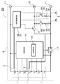
- the battery packs 100 and 200 shown in the circuit diagrams of FIGS. 1 and 2 store a plurality of batteries 1 in an outer case 10.
- the battery packs 100 and 200 include a main temperature sensor 2 that detects the battery temperature in the outer case 10.
- the battery packs 100 and 200 include positive and negative power supply terminals 11 connected to the output side of the battery 1 and a temperature terminal 12 connected to the main temperature sensor 2.
- the power supply terminal 11 and the temperature terminal 12 are provided in the outer case 10 so as to be connected to the power supply contact and the temperature detection contact on the main device side in a state where the battery packs 100 and 200 are set in the main device.
- the power supply terminal 11 and the temperature terminal 12 are fixed to the exterior case 10 and exposed to the outside, or are fixed to a circuit board disposed inside the exterior case 10 so as to be exposed to the outside from an electrode window provided in the exterior case 10. Exposed. *
- the battery packs 100 and 200 shown in the circuit diagrams of FIGS. 1 and 2 do not connect the power terminal 11 directly to the battery 1, but connect one power terminal 11 to one of the batteries 1 via the charge / discharge switch 13. Connected to the output terminal.
- the charge / discharge switch 13 is connected between the negative power supply terminal 11 and the battery 1.
- the charge / discharge switch 13 is a semiconductor switching element such as an FET, and is controlled to be turned on / off by a control circuit 14 including a protection circuit 15 for the battery 1.
- the protection circuit 15 detects the voltage of each battery 1 and controls the charge / discharge switch 13 so as to keep the voltages of all the batteries 1 within a set range.
- the protection circuit 15 switches the charging / discharging switch 13 to turn off the voltage of the battery 1.
- the battery is kept in the set range to prevent overcharge and overdischarge of the battery 1.
- the main temperature sensor 2 is a thermistor. When the temperature rises, the thermistor decreases its electrical resistance value and detects the temperature. The thermistor has a large change in electrical resistance value with respect to temperature change, and can accurately detect the temperature. As the main temperature sensor 2, all other elements whose electric resistance value changes as the temperature changes, for example, a varistor or the like is used.
- the main temperature sensor 2 detects the temperature of the battery 1 by being placed in a thermally coupled state on the surface of the battery 1 where the temperature of the battery packs 100 and 200 is highest in the normal state. However, the main temperature sensor 2 can be arranged at a position approaching the surface of the battery 1 to detect the temperature of the battery 1.
- the temperature terminal 12 is connected to a temperature detection contact of the main device, and transmits the temperature of the battery 1 detected by the main temperature sensor 2 to the main device.
- the main device protects the battery 1 by controlling the charge / discharge current at the temperature of the battery 1 transmitted from the temperature terminals 12 of the battery packs 100 and 200. Since the temperature of the battery 1 is necessary for charge / discharge control, the main temperature sensor 2 continuously performs temperature detection and output of the detected temperature to the temperature terminal 12.
- the battery packs 100 and 200 of FIGS. 1 and 2 include a sub temperature sensor 3 in the outer case 10 in addition to the main temperature sensor 2.
- the sub-temperature sensor 3 is a temperature detection element such as a thermistor similar to the main temperature sensor 2, and is located at a position different from the main temperature sensor 2, and is different from the battery 1 from which the main temperature sensor 2 detects the temperature. The temperature or the temperature of another part in the outer case 10 is detected.
- the sub temperature sensor 3 detects the temperature of the battery 1 arranged at a position away from the main temperature sensor 2 or is arranged at a position where the temperature is likely to rise to detect the temperature inside the outer case 10.
- the sub temperature sensor 3 is not directly connected to the temperature terminal 12.
- a main switch 4 that is turned on / off by the sub temperature sensor 3 is connected between the main temperature sensor 2 and the temperature terminal 12.
- the main switch 4 is switched on and off at the temperature detected by the sub temperature sensor 3.
- a temperature monitoring circuit 5 that switches the main switch 4 on and off at the temperature detected by the sub temperature sensor 3 is provided.
- the temperature monitoring circuit 5 includes a comparator that determines whether or not the temperature detected by the sub temperature sensor 3 exceeds an upper threshold value within a predetermined temperature range (for example, 0 to 80 ° C.).
- the temperature monitoring circuit 5A of the battery pack 100 in FIG. 1 compares the detected temperature of the sub temperature sensor 3 with the upper limit threshold with a comparator. When the detected temperature becomes higher than the upper limit threshold, it is determined as an abnormal temperature state and the main switch Switch 4 off.
- the upper limit threshold value for comparing the detected temperatures is set to an optimum temperature that is, for example, 70 ° C. or higher and 80 ° C. or lower.
- the electrical resistance value of the sub temperature sensor 3 varies depending on the temperature. Therefore, the comparator of the temperature monitoring circuit 5A compares the voltage value that changes according to the electrical resistance value of the sub temperature sensor 3 with the upper threshold value, and determines whether or not the detected temperature is higher than the upper threshold value.
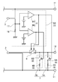
- FIG. 3 shows a specific circuit diagram of the temperature monitoring circuit 5A including the comparator 6.
- the comparator 6 inputs a reference voltage on one input side, inputs a detection voltage that changes according to the detection temperature of the sub temperature sensor 3 on the other input side, compares the detection voltage with the reference voltage, and detects the detected temperature. Detect that it is higher than the upper threshold.
- the comparator 6 of the temperature monitoring circuit 5A in FIG. 3 inputs a reference voltage to the negative input terminal, and connects the positive power line to the positive input terminal via the sub temperature sensor 3 and An input resistor 16 is connected between the input terminal on the side and the ground line on the negative side. That is, the temperature monitoring circuit 5A of FIG. 3 connects the series circuit of the sub temperature sensor 3 and the input resistor 16 between the positive power supply line and the negative ground line, and also connects the sub temperature sensor 3 and the input resistance. The connection point 17 with 16 is input to the input terminal on the plus side of the comparator 6.
- the temperature monitoring circuit 5A uses the reference voltage of the comparator 6 as a voltage input at a temperature at which the detected temperature of the sub temperature sensor 3 is an upper threshold, for example, 80 ° C.
- the comparator 6 outputs “Low” when the detected temperature of the sub temperature sensor 3 is lower than the upper threshold value of 80 ° C., and thus outputs “Low”, and the detected temperature is higher than 80 ° C. If it is high, the input detection voltage becomes higher than the reference voltage and “High” is output. Therefore, the comparator 6 switches the main switch 4 off with the abnormal signal output when determining that the detected temperature is in the abnormal temperature state higher than the upper limit threshold as “High”.
- the above temperature monitoring circuit 5A can compare the detected temperature with the upper threshold in real time. However, the temperature monitoring circuit 5 converts an electrical resistance value detected by the sub temperature sensor 3 or an analog signal obtained by converting the electrical resistance value into a voltage value into a digital signal, and stores the digital signal. It can also be determined whether or not the detected temperature is higher than the upper threshold value compared to the upper threshold value.
- the temperature monitoring circuit 5A switches the main switch 4 to the OFF state.
- the temperature terminal 12 is not connected to the main temperature sensor 2, and the output impedance of the temperature terminal 12 becomes higher than the electrical resistance value of the main temperature sensor 2.
- the main switch 4 is kept on, so that the main temperature sensor 2 is connected to the temperature terminal 12 and the signal of the main temperature sensor 2 is the temperature terminal. 12 to the main device.
- the battery 1 determines that the temperature detected by the sub temperature sensor 3 is higher than the upper limit threshold of the predetermined temperature range as an abnormal temperature state and switches the main switch 4 to the off state. Therefore, the battery temperature is abnormal. It can be detected by the sub temperature sensor 3 and transmitted from the temperature terminal 12 to the main device. However, in the battery pack of the present invention, the state where the detected temperature is lower than the lower limit threshold of a predetermined temperature range set to, for example, 0 ° C. to 5 ° C. is set as the abnormal temperature state and the main switch 4 is switched to the off state. You can also This battery pack transmits an abnormal temperature state that the battery temperature is abnormally low to the main device.
- the temperature monitoring circuit 5B in this figure includes a first comparator 6A that compares the detected temperature with an upper limit threshold value in a predetermined temperature range, and a second comparator 6B that compares the detected temperature with a lower limit threshold value in a predetermined temperature range. ing.
- the first comparator 6A sets the upper limit threshold for comparing the detected temperatures to, for example, 70 ° C. to 80 ° C., and if the detected temperature of the sub temperature sensor 3 is higher than the upper limit threshold, it is determined as an abnormal temperature state and abnormal Output a signal.
- the second comparator 6B sets a lower threshold value for comparing the detected temperatures to 0 ° C. to 5 ° C., for example. If the detected temperature of the sub temperature sensor 3 is lower than the lower threshold value, it is determined as an abnormal temperature state and abnormal. Output a signal.
- FIG. 4 shows a temperature monitoring circuit 5B including two comparators 6.
- the comparator 6 in this figure is a differential amplifier that inputs a reference voltage to one input side.
- the comparator 6 inputs a detection voltage that varies depending on the temperature detected by the sub temperature sensor 3 to the other input side, compares the detection voltage with a reference voltage, switches the output between “Low” and “High”, and outputs an abnormal signal. Is output.
- connection point 17 between the sensor 3 and the input resistor 16 is connected to the other input side of the comparator 6, and a detection voltage that changes depending on the detection temperature of the sub temperature sensor 3 is input to the comparator 6.
- the first comparator 6A inputs the reference voltage to the negative input terminal, and connects the connection point 17 between the sub temperature sensor 3 and the input resistor 16 to the positive input terminal to input the detection voltage. Yes.
- the temperature monitoring circuit 5B uses the reference voltage of the first comparator 6A as a voltage that is input at a temperature at which the detected temperature of the sub temperature sensor 3 is the upper threshold, for example, 80 ° C.
- the first comparator 6A outputs “Low” when the detected temperature of the sub temperature sensor 3 is lower than the upper limit threshold of 80 ° C., and therefore outputs “Low”, and the detected temperature is When the temperature is higher than 80 ° C., the input detection voltage becomes higher than the reference voltage and “High” is output. Therefore, the first comparator 6A switches the main switch 4 off by setting the abnormal signal to “High”.
- the second comparator 6B inputs the reference voltage to the positive input terminal, and connects the connection point 17 between the sub-temperature sensor 3 and the input resistor 16 to the negative input terminal to input the detection voltage. Yes.
- the temperature monitoring circuit 5B uses the reference voltage of the second comparator 6B as a voltage that is input at a temperature at which the detected temperature of the sub temperature sensor 3 is a lower threshold, for example, 0 ° C.
- the second comparator 6B outputs “Low” when the detected temperature of the sub temperature sensor 3 is higher than the lower limit threshold value of 0 ° C., and therefore outputs “Low”.
- the input detection voltage is lower than the reference voltage and “High” is output. Therefore, the second comparator 6B switches the main switch 4 off by setting the abnormal signal to “High”.
- the above temperature monitoring circuit 5B can also compare the detected temperature with a threshold value within a predetermined temperature range in real time. However, the temperature monitoring circuit 5 converts the electrical resistance value detected by the sub temperature sensor 3 or an analog signal obtained by converting the electrical resistance value into a voltage into a digital signal, and stores the digital signal. It can also be determined whether the detected temperature is higher than the upper threshold or whether the detected temperature is lower than the lower threshold compared to the upper threshold and the lower threshold.
- the temperature monitoring circuit 5B compares the detected temperature of the sub temperature sensor 3 with a threshold value, outputs an abnormal signal when the detected temperature exceeds a threshold value in a predetermined temperature range, and switches the main switch 4 from on to off,
- the main temperature sensor 2 is disconnected from the temperature terminal 12. Therefore, in a state where the detected temperature of the sub temperature sensor 3 is higher than the upper limit threshold or lower than the lower limit threshold, that is, in a range where the detected temperature exceeds the threshold of the predetermined temperature range, the temperature signal of the main temperature sensor 2 is used as the temperature terminal. 12 is not output.
- the main switch 4 is turned off and the output impedance of the temperature terminal 12 changes, the main device determines that the detected temperature of the sub temperature sensor 3 has exceeded a predetermined temperature range threshold.
- the battery pack 200 in FIG. 2 is controlled by the temperature monitoring circuit 5B in order to set the output impedance of the temperature terminal 12 to a specific electric resistance value in a state where the temperature detected by the sub temperature sensor 3 exceeds a predetermined temperature range threshold.
- the resistance circuit 7 is provided.
- the resistance circuit 7 is a series circuit of a sub switch 8 and a resistor 9. One end of the resistance circuit 7 is connected between the temperature terminal 12 and the main switch 4. Further, the other end of the resistance circuit 7 shown in FIG. 2 is connected to one of the power supply terminals 11 (a negative power supply terminal in the figure). That is, the resistance circuit 7 is connected between the temperature terminal 12 and one power supply terminal 11.
- the sub switch 8 of the resistance circuit 7 is turned on when the main switch 4 is turned off, and the output impedance of the temperature terminal 12 is set to the electrical resistance value of the resistor 9.
- the resistors 9 of the two resistance circuits 7 have electrical resistance values different from those of the main temperature sensor 2. Precisely, since the electric resistance value of the main temperature sensor 2 changes according to the detected temperature, the electric resistance value of the resistor 9 is set to a resistance value outside the range of resistance values that the main temperature sensor 2 can take due to temperature change. That is, the electric resistance value of the resistor 9 is set to a value smaller than the minimum electric resistance value changing within a predetermined temperature range of the main temperature sensor 2 or larger than the maximum electric resistance value.
- the output impedance of the temperature terminal 12 is changed to the main temperature sensor 2 in a state where the main switch 4 is turned off and the sub switch 8 is turned on. This is because an abnormal temperature state is transmitted to the main device as an electrical resistance value different from the electrical resistance value.
- the sub switch 8 of the resistance circuit 7 is controlled by the temperature monitoring circuit 5B.
- the temperature monitoring circuit 5B switches the main switch 4 to OFF, switches one sub switch 8 to ON, and outputs the temperature terminal 12
- the impedance is set to the electrical resistance value of the resistor 9 of the resistance circuit 7 that is switched to the ON state.
- the battery pack 200 of FIG. 2 and FIG. 4 has two resistance circuits 7, that is, a first resistance circuit 7A having a different electrical resistance value of the resistor 9, and a second resistance circuit 7B connected in parallel.
- the temperature terminal 12 and one power supply terminal 11 are connected.
- the first sub switch 8A of the first resistor circuit 7A is controlled to be turned on / off by the first comparator 6A
- the second sub switch 8B of the second resistor circuit 7B is controlled to be turned on / off by the second comparator 6B.
- the electrical resistance values of the first resistor 9A of the first resistor circuit 7A and the second resistor 9B of the second resistor circuit 7B are outside the range of resistance values that the main temperature sensor 2 can take due to temperature changes. Resistance value.
- the resistance values of the first resistor 9A and the second resistor 9B are different from each other.
- the electric resistance value of the first resistor 9 ⁇ / b> A is larger than the maximum electric resistance value that the main temperature sensor 2 changes, and the electric resistance value of the second resistor 9 ⁇ / b> B changes in the main temperature sensor 2.
- a value smaller than the minimum electric resistance value is set.
- the first comparator 6A of the temperature monitoring circuit 5B compares the detected temperature of the sub temperature sensor 3 with the upper limit threshold of a predetermined temperature range, and outputs an abnormal signal when the detected temperature is higher than the upper limit threshold.
- the switch 4 is turned off and the first sub switch 8A is turned on. In this state, the output impedance of the temperature terminal 12 becomes the electric resistance value of the first resistor 9A.
- the second comparator 6B of the temperature monitoring circuit 5B compares the detected temperature of the sub temperature sensor 3 with the lower limit threshold of the predetermined temperature range, and outputs an abnormal signal when the detected temperature is lower than the lower limit threshold.
- the switch 4 is switched off and the second sub switch 8B is switched on. In this state, the output impedance of the temperature terminal 12 becomes the electric resistance value of the second resistor 9B.
- the main device determines that the temperature detected by the sub temperature sensor 3 is higher than the upper limit threshold when the output impedance of the temperature terminal 12 is equal to the electric resistance value of the first resistor 9A, and the output impedance of the temperature terminal 12 In the state where the electric resistance value of the second resistor 9B is reached, it is determined that the temperature detected by the sub-temperature sensor 3 has fallen below the lower threshold.
- the battery pack 200 of FIG. 2 changes the output impedance of the temperature terminal 12 by switching the sub-switch 8 of the two resistance circuits 7 on and off with the temperature monitoring circuit 5B, and transmits the abnormal temperature state to the main device.
- the battery pack can be provided with three or more resistance circuits, and the sub-switches of each resistance circuit can be controlled to be turned on and off to transmit three or more abnormal signals to the main device.
- three or more threshold values for comparing the detected temperatures of the sub temperature sensors can be set, and the fact that the detected temperature exceeds any threshold value can be transmitted to the main device.
- a lower limit threshold value of 0 ° C., a high temperature threshold value of 70 ° C., and an upper limit threshold value of 80 ° C. are provided, and the detected temperature of the sub temperature sensor 3 is any abnormality of 0 ° C. or lower, 70 ° C. or higher, or 80 ° C. or higher. It can be transmitted to the main device as a temperature state.
- the sub temperature sensor 3 detects the temperature of the battery 1 different from the battery 1 for which the main temperature sensor 2 detects the temperature, but the charge / discharge switch 13 and the protection circuit mounted on the circuit board.
- the temperature of a circuit component such as 15 may be detected.
- the circuit component can be transmitted to the main device as an abnormal temperature state.
- one sub temperature sensor 3 is arranged, but a plurality of sub temperature sensors 3 may be arranged.
- the temperature monitoring circuit 5 compares the plurality of detected temperatures detected by the plurality of sub temperature sensors 3 with a predetermined temperature range, and any of the plurality of detected temperatures is higher than the predetermined temperature range, or In a low state, the main switch 4 can be controlled to be switched off, and an abnormal signal can be transmitted from the temperature terminal 12 to the main device.
- one sub temperature sensor 3 is arranged, but a plurality of sub temperature sensors 3 may be arranged.
- one to a plurality of resistance circuits 7 can be arranged corresponding to each of the plurality of sub temperature sensors 3.
- One end of the resistance circuit 7 is connected between the temperature terminal 12 and the main switch 4, and the other end is connected to one of the power supply terminals 11.
- any of the sub temperature sensors 3 can be transmitted to the main device as an abnormal temperature state.
- the present invention can be effectively used for a battery pack that can be safely used by transmitting an abnormal temperature to the main device while having a simple structure including one temperature terminal.
Landscapes
- Engineering & Computer Science (AREA)
- Manufacturing & Machinery (AREA)
- Chemical & Material Sciences (AREA)
- Chemical Kinetics & Catalysis (AREA)
- Electrochemistry (AREA)
- General Chemical & Material Sciences (AREA)
- Power Engineering (AREA)
- Secondary Cells (AREA)
- Battery Mounting, Suspending (AREA)
- Charge And Discharge Circuits For Batteries Or The Like (AREA)
Abstract
La présente invention fournit de façon sûre une pluralité de signaux de température à partir d'un terminal unique de température en utilisant une configuration de circuit simple. L'invention concerne un bloc-batterie qui comprend : une pluralité de batteries (1) ; un capteur de température principal (2) qui détecte une température de batterie ; un terminal de température (12) formé en étant connecté au capteur de température principal (2) ; un capteur de température auxiliaire (3) qui détecte la température d'un bloc-batterie (100, 200) à une position différente de celle du capteur de température principal (2) ; un commutateur principal (4) qui est connecté entre le capteur de température principal (2) et le terminal de température (12), qui fournit, dans un état de Marche, un signal du capteur de température principal (2) au terminal de température (12) et déconnecte, dans un état d'Arrêt, le capteur de température principal (2) du terminal de température (12) ; et un circuit de surveillance de température (5) qui commande le commutateur principal (4) devant être sur Marche/Arrêt en fonction de la température détectée du capteur de température auxiliaire (3). Le circuit de surveillance de température (5) compare la température détectée qui a été détectée par le capteur de température auxiliaire (3) avec une plage de température prescrite, et dans le cas d'un état de température anormal où la température détectée est supérieure ou inférieure à la plage de température prescrite, effectue une commande pour commuter le commutateur principal (4) vers l'état d'Arrêt et fournit un signal d'anomalie à partir du terminal de température (12).
Priority Applications (1)
| Application Number | Priority Date | Filing Date | Title |
|---|---|---|---|
| EP15872181.1A EP3240097B1 (fr) | 2014-12-25 | 2015-12-09 | Bloc-batterie |
Applications Claiming Priority (2)
| Application Number | Priority Date | Filing Date | Title |
|---|---|---|---|
| JP2014-262576 | 2014-12-25 | ||
| JP2014262576A JP2018029407A (ja) | 2014-12-25 | 2014-12-25 | 電池パック |
Publications (1)
| Publication Number | Publication Date |
|---|---|
| WO2016103606A1 true WO2016103606A1 (fr) | 2016-06-30 |
Family
ID=56149675
Family Applications (1)
| Application Number | Title | Priority Date | Filing Date |
|---|---|---|---|
| PCT/JP2015/006128 Ceased WO2016103606A1 (fr) | 2014-12-25 | 2015-12-09 | Bloc-batterie |
Country Status (3)
| Country | Link |
|---|---|
| EP (1) | EP3240097B1 (fr) |
| JP (1) | JP2018029407A (fr) |
| WO (1) | WO2016103606A1 (fr) |
Cited By (2)
| Publication number | Priority date | Publication date | Assignee | Title |
|---|---|---|---|---|
| US20210143664A1 (en) * | 2019-11-11 | 2021-05-13 | Basso Industry Corp. | Battery device and battery charging system |
| CN118507885A (zh) * | 2024-04-17 | 2024-08-16 | 惠州市乐亿通科技股份有限公司 | 锂电池温度监测系统及方法 |
Families Citing this family (4)
| Publication number | Priority date | Publication date | Assignee | Title |
|---|---|---|---|---|
| CN110907056A (zh) * | 2018-09-14 | 2020-03-24 | 宁德时代新能源科技股份有限公司 | 一种电池组温度检测系统 |
| CN120300966A (zh) * | 2019-06-12 | 2025-07-11 | 苏州宝时得电动工具有限公司 | 一种电池包 |
| US11233282B2 (en) | 2019-06-17 | 2022-01-25 | Makita Corporation | Battery-powered portable tool |
| JP7323800B2 (ja) * | 2019-10-18 | 2023-08-09 | ミツミ電機株式会社 | 二次電池保護回路、二次電池保護装置、電池パック及び温度検出回路 |
Citations (4)
| Publication number | Priority date | Publication date | Assignee | Title |
|---|---|---|---|---|
| JP2009044823A (ja) * | 2007-08-07 | 2009-02-26 | Mitsumi Electric Co Ltd | 電池パック |
| JP2009117262A (ja) * | 2007-11-08 | 2009-05-28 | Sanyo Electric Co Ltd | パック電池 |
| JP2012501061A (ja) * | 2008-08-28 | 2012-01-12 | ローベルト ボツシユ ゲゼルシヤフト ミツト ベシユレンクテル ハフツング | 蓄電池パック |
| WO2014141809A1 (fr) * | 2013-03-13 | 2014-09-18 | Necエナジーデバイス株式会社 | Bloc de batterie, corps mobile et procédé de commande |
Family Cites Families (3)
| Publication number | Priority date | Publication date | Assignee | Title |
|---|---|---|---|---|
| JP4278622B2 (ja) * | 2004-03-18 | 2009-06-17 | 三洋電機株式会社 | 電源装置 |
| JP4931378B2 (ja) * | 2005-07-06 | 2012-05-16 | 三洋電機株式会社 | 車両用の電源装置 |
| EP2528189B1 (fr) * | 2010-01-22 | 2018-11-28 | Toyota Jidosha Kabushiki Kaisha | Système de gestion de charge de batterie |
-
2014
- 2014-12-25 JP JP2014262576A patent/JP2018029407A/ja active Pending
-
2015
- 2015-12-09 WO PCT/JP2015/006128 patent/WO2016103606A1/fr not_active Ceased
- 2015-12-09 EP EP15872181.1A patent/EP3240097B1/fr not_active Not-in-force
Patent Citations (4)
| Publication number | Priority date | Publication date | Assignee | Title |
|---|---|---|---|---|
| JP2009044823A (ja) * | 2007-08-07 | 2009-02-26 | Mitsumi Electric Co Ltd | 電池パック |
| JP2009117262A (ja) * | 2007-11-08 | 2009-05-28 | Sanyo Electric Co Ltd | パック電池 |
| JP2012501061A (ja) * | 2008-08-28 | 2012-01-12 | ローベルト ボツシユ ゲゼルシヤフト ミツト ベシユレンクテル ハフツング | 蓄電池パック |
| WO2014141809A1 (fr) * | 2013-03-13 | 2014-09-18 | Necエナジーデバイス株式会社 | Bloc de batterie, corps mobile et procédé de commande |
Non-Patent Citations (1)
| Title |
|---|
| See also references of EP3240097A4 * |
Cited By (3)
| Publication number | Priority date | Publication date | Assignee | Title |
|---|---|---|---|---|
| US20210143664A1 (en) * | 2019-11-11 | 2021-05-13 | Basso Industry Corp. | Battery device and battery charging system |
| US11742686B2 (en) * | 2019-11-11 | 2023-08-29 | Basso Industry Corp. | Battery device and battery charging system |
| CN118507885A (zh) * | 2024-04-17 | 2024-08-16 | 惠州市乐亿通科技股份有限公司 | 锂电池温度监测系统及方法 |
Also Published As
| Publication number | Publication date |
|---|---|
| EP3240097A4 (fr) | 2017-11-01 |
| EP3240097A1 (fr) | 2017-11-01 |
| JP2018029407A (ja) | 2018-02-22 |
| EP3240097B1 (fr) | 2018-08-01 |
Similar Documents
| Publication | Publication Date | Title |
|---|---|---|
| WO2016103606A1 (fr) | Bloc-batterie | |
| JP5219486B2 (ja) | パック電池 | |
| EP3525314B1 (fr) | Dispositif et procédé de prévention de surcharge | |
| KR101973054B1 (ko) | 배터리 팩 및 배터리 팩의 제어 방법 | |
| CN101699646B (zh) | 电池监控和平衡电路 | |
| JP3848574B2 (ja) | 充放電制御装置 | |
| JP2023138541A (ja) | 二次電池保護装置、電池パック及び二次電池保護装置の制御方法 | |
| JP4911430B2 (ja) | 充電装置 | |
| CN110832732B (zh) | 电池的保护电路和具备该保护电路的电源装置 | |
| WO2018054143A1 (fr) | Batterie, terminal, et système de charge | |
| JP5219463B2 (ja) | パック電池 | |
| KR102258826B1 (ko) | 과충전 방지 장치 및 방법 | |
| USRE50397E1 (en) | Battery pack | |
| JP5503430B2 (ja) | 出力停止スイッチ付き電池パック | |
| JP2008278583A (ja) | 充放電システム | |
| JP6370137B2 (ja) | 充放電制御回路及びバッテリ装置 | |
| JP2009095162A (ja) | 電池パックおよび電池パックを用いた電動工具 | |
| WO2017148123A1 (fr) | Dispositif de protection de batterie et ensemble d'alimentation | |
| JP5458647B2 (ja) | 保護回路 | |
| EP3109927B1 (fr) | Combinaison électrique | |
| JP2017104006A (ja) | 充放電制御回路及びバッテリ装置 | |
| JP2014039400A (ja) | 電池パック、充電装置、充電システムおよび充電方法 | |
| JP2013165631A (ja) | スイッチ回路及びパック電池 | |
| KR20130025931A (ko) | 배터리 팩 및 이의 제어 방법 | |
| KR102137698B1 (ko) | 배터리 보호 회로 장치 |
Legal Events
| Date | Code | Title | Description |
|---|---|---|---|
| 121 | Ep: the epo has been informed by wipo that ep was designated in this application |
Ref document number: 15872181 Country of ref document: EP Kind code of ref document: A1 |
|
| REEP | Request for entry into the european phase |
Ref document number: 2015872181 Country of ref document: EP |
|
| NENP | Non-entry into the national phase |
Ref country code: DE |
|
| NENP | Non-entry into the national phase |
Ref country code: JP |