EP3240137A1 - Système d'alimentation électrique automatique, dispositif d'alimentation électrique automatique, et système mobile autonome - Google Patents
Système d'alimentation électrique automatique, dispositif d'alimentation électrique automatique, et système mobile autonome Download PDFInfo
- Publication number
- EP3240137A1 EP3240137A1 EP16764404.6A EP16764404A EP3240137A1 EP 3240137 A1 EP3240137 A1 EP 3240137A1 EP 16764404 A EP16764404 A EP 16764404A EP 3240137 A1 EP3240137 A1 EP 3240137A1
- Authority
- EP
- European Patent Office
- Prior art keywords
- power supply
- automatic power
- supply device
- autonomous moving
- moving device
- Prior art date
- Legal status (The legal status is an assumption and is not a legal conclusion. Google has not performed a legal analysis and makes no representation as to the accuracy of the status listed.)
- Granted
Links
Images




Classifications
-
- B—PERFORMING OPERATIONS; TRANSPORTING
- B60—VEHICLES IN GENERAL
- B60L—PROPULSION OF ELECTRICALLY-PROPELLED VEHICLES; SUPPLYING ELECTRIC POWER FOR AUXILIARY EQUIPMENT OF ELECTRICALLY-PROPELLED VEHICLES; ELECTRODYNAMIC BRAKE SYSTEMS FOR VEHICLES IN GENERAL; MAGNETIC SUSPENSION OR LEVITATION FOR VEHICLES; MONITORING OPERATING VARIABLES OF ELECTRICALLY-PROPELLED VEHICLES; ELECTRIC SAFETY DEVICES FOR ELECTRICALLY-PROPELLED VEHICLES
- B60L53/00—Methods of charging batteries, specially adapted for electric vehicles; Charging stations or on-board charging equipment therefor; Exchange of energy storage elements in electric vehicles
- B60L53/10—Methods of charging batteries, specially adapted for electric vehicles; Charging stations or on-board charging equipment therefor; Exchange of energy storage elements in electric vehicles characterised by the energy transfer between the charging station and the vehicle
- B60L53/14—Conductive energy transfer
-
- B—PERFORMING OPERATIONS; TRANSPORTING
- B60—VEHICLES IN GENERAL
- B60L—PROPULSION OF ELECTRICALLY-PROPELLED VEHICLES; SUPPLYING ELECTRIC POWER FOR AUXILIARY EQUIPMENT OF ELECTRICALLY-PROPELLED VEHICLES; ELECTRODYNAMIC BRAKE SYSTEMS FOR VEHICLES IN GENERAL; MAGNETIC SUSPENSION OR LEVITATION FOR VEHICLES; MONITORING OPERATING VARIABLES OF ELECTRICALLY-PROPELLED VEHICLES; ELECTRIC SAFETY DEVICES FOR ELECTRICALLY-PROPELLED VEHICLES
- B60L50/00—Electric propulsion with power supplied within the vehicle
- B60L50/50—Electric propulsion with power supplied within the vehicle using propulsion power supplied by batteries or fuel cells
- B60L50/60—Electric propulsion with power supplied within the vehicle using propulsion power supplied by batteries or fuel cells using power supplied by batteries
-
- B—PERFORMING OPERATIONS; TRANSPORTING
- B60—VEHICLES IN GENERAL
- B60L—PROPULSION OF ELECTRICALLY-PROPELLED VEHICLES; SUPPLYING ELECTRIC POWER FOR AUXILIARY EQUIPMENT OF ELECTRICALLY-PROPELLED VEHICLES; ELECTRODYNAMIC BRAKE SYSTEMS FOR VEHICLES IN GENERAL; MAGNETIC SUSPENSION OR LEVITATION FOR VEHICLES; MONITORING OPERATING VARIABLES OF ELECTRICALLY-PROPELLED VEHICLES; ELECTRIC SAFETY DEVICES FOR ELECTRICALLY-PROPELLED VEHICLES
- B60L53/00—Methods of charging batteries, specially adapted for electric vehicles; Charging stations or on-board charging equipment therefor; Exchange of energy storage elements in electric vehicles
- B60L53/10—Methods of charging batteries, specially adapted for electric vehicles; Charging stations or on-board charging equipment therefor; Exchange of energy storage elements in electric vehicles characterised by the energy transfer between the charging station and the vehicle
- B60L53/14—Conductive energy transfer
- B60L53/16—Connectors, e.g. plugs or sockets, specially adapted for charging electric vehicles
-
- B—PERFORMING OPERATIONS; TRANSPORTING
- B60—VEHICLES IN GENERAL
- B60L—PROPULSION OF ELECTRICALLY-PROPELLED VEHICLES; SUPPLYING ELECTRIC POWER FOR AUXILIARY EQUIPMENT OF ELECTRICALLY-PROPELLED VEHICLES; ELECTRODYNAMIC BRAKE SYSTEMS FOR VEHICLES IN GENERAL; MAGNETIC SUSPENSION OR LEVITATION FOR VEHICLES; MONITORING OPERATING VARIABLES OF ELECTRICALLY-PROPELLED VEHICLES; ELECTRIC SAFETY DEVICES FOR ELECTRICALLY-PROPELLED VEHICLES
- B60L53/00—Methods of charging batteries, specially adapted for electric vehicles; Charging stations or on-board charging equipment therefor; Exchange of energy storage elements in electric vehicles
- B60L53/30—Constructional details of charging stations
- B60L53/35—Means for automatic or assisted adjustment of the relative position of charging devices and vehicles
-
- B—PERFORMING OPERATIONS; TRANSPORTING
- B60—VEHICLES IN GENERAL
- B60L—PROPULSION OF ELECTRICALLY-PROPELLED VEHICLES; SUPPLYING ELECTRIC POWER FOR AUXILIARY EQUIPMENT OF ELECTRICALLY-PROPELLED VEHICLES; ELECTRODYNAMIC BRAKE SYSTEMS FOR VEHICLES IN GENERAL; MAGNETIC SUSPENSION OR LEVITATION FOR VEHICLES; MONITORING OPERATING VARIABLES OF ELECTRICALLY-PROPELLED VEHICLES; ELECTRIC SAFETY DEVICES FOR ELECTRICALLY-PROPELLED VEHICLES
- B60L53/00—Methods of charging batteries, specially adapted for electric vehicles; Charging stations or on-board charging equipment therefor; Exchange of energy storage elements in electric vehicles
- B60L53/30—Constructional details of charging stations
- B60L53/35—Means for automatic or assisted adjustment of the relative position of charging devices and vehicles
- B60L53/36—Means for automatic or assisted adjustment of the relative position of charging devices and vehicles by positioning the vehicle
-
- B—PERFORMING OPERATIONS; TRANSPORTING
- B60—VEHICLES IN GENERAL
- B60L—PROPULSION OF ELECTRICALLY-PROPELLED VEHICLES; SUPPLYING ELECTRIC POWER FOR AUXILIARY EQUIPMENT OF ELECTRICALLY-PROPELLED VEHICLES; ELECTRODYNAMIC BRAKE SYSTEMS FOR VEHICLES IN GENERAL; MAGNETIC SUSPENSION OR LEVITATION FOR VEHICLES; MONITORING OPERATING VARIABLES OF ELECTRICALLY-PROPELLED VEHICLES; ELECTRIC SAFETY DEVICES FOR ELECTRICALLY-PROPELLED VEHICLES
- B60L53/00—Methods of charging batteries, specially adapted for electric vehicles; Charging stations or on-board charging equipment therefor; Exchange of energy storage elements in electric vehicles
- B60L53/30—Constructional details of charging stations
- B60L53/35—Means for automatic or assisted adjustment of the relative position of charging devices and vehicles
- B60L53/37—Means for automatic or assisted adjustment of the relative position of charging devices and vehicles using optical position determination, e.g. using cameras
-
- G—PHYSICS
- G05—CONTROLLING; REGULATING
- G05D—SYSTEMS FOR CONTROLLING OR REGULATING NON-ELECTRIC VARIABLES
- G05D1/00—Control of position, course, altitude or attitude of land, water, air or space vehicles, e.g. using automatic pilots
- G05D1/02—Control of position or course in two dimensions
-
- G—PHYSICS
- G05—CONTROLLING; REGULATING
- G05D—SYSTEMS FOR CONTROLLING OR REGULATING NON-ELECTRIC VARIABLES
- G05D1/00—Control of position, course, altitude or attitude of land, water, air or space vehicles, e.g. using automatic pilots
- G05D1/02—Control of position or course in two dimensions
- G05D1/021—Control of position or course in two dimensions specially adapted to land vehicles
- G05D1/0212—Control of position or course in two dimensions specially adapted to land vehicles with means for defining a desired trajectory
-
- H—ELECTRICITY
- H02—GENERATION; CONVERSION OR DISTRIBUTION OF ELECTRIC POWER
- H02J—ELECTRIC POWER NETWORKS; CIRCUIT ARRANGEMENTS OR SYSTEMS FOR SUPPLYING OR DISTRIBUTING ELECTRIC POWER; SYSTEMS FOR STORING ELECTRIC ENERGY
- H02J7/00—Circuit arrangements for charging or discharging batteries or for supplying loads from batteries
- H02J7/70—Circuit arrangements for charging or discharging batteries or for supplying loads from batteries characterised by the mechanical construction
-
- H—ELECTRICITY
- H02—GENERATION; CONVERSION OR DISTRIBUTION OF ELECTRIC POWER
- H02J—ELECTRIC POWER NETWORKS; CIRCUIT ARRANGEMENTS OR SYSTEMS FOR SUPPLYING OR DISTRIBUTING ELECTRIC POWER; SYSTEMS FOR STORING ELECTRIC ENERGY
- H02J2105/00—Networks for supplying or distributing electric power characterised by their spatial reach or by the load
- H02J2105/30—Networks for supplying or distributing electric power characterised by their spatial reach or by the load the load networks being external to vehicles, i.e. exchanging power with vehicles
- H02J2105/33—Networks for supplying or distributing electric power characterised by their spatial reach or by the load the load networks being external to vehicles, i.e. exchanging power with vehicles exchanging power with road vehicles
- H02J2105/37—Networks for supplying or distributing electric power characterised by their spatial reach or by the load the load networks being external to vehicles, i.e. exchanging power with vehicles exchanging power with road vehicles exchanging power with electric vehicles [EV] or with hybrid electric vehicles [HEV]
-
- Y—GENERAL TAGGING OF NEW TECHNOLOGICAL DEVELOPMENTS; GENERAL TAGGING OF CROSS-SECTIONAL TECHNOLOGIES SPANNING OVER SEVERAL SECTIONS OF THE IPC; TECHNICAL SUBJECTS COVERED BY FORMER USPC CROSS-REFERENCE ART COLLECTIONS [XRACs] AND DIGESTS
- Y02—TECHNOLOGIES OR APPLICATIONS FOR MITIGATION OR ADAPTATION AGAINST CLIMATE CHANGE
- Y02T—CLIMATE CHANGE MITIGATION TECHNOLOGIES RELATED TO TRANSPORTATION
- Y02T10/00—Road transport of goods or passengers
- Y02T10/60—Other road transportation technologies with climate change mitigation effect
- Y02T10/70—Energy storage systems for electromobility, e.g. batteries
-
- Y—GENERAL TAGGING OF NEW TECHNOLOGICAL DEVELOPMENTS; GENERAL TAGGING OF CROSS-SECTIONAL TECHNOLOGIES SPANNING OVER SEVERAL SECTIONS OF THE IPC; TECHNICAL SUBJECTS COVERED BY FORMER USPC CROSS-REFERENCE ART COLLECTIONS [XRACs] AND DIGESTS
- Y02—TECHNOLOGIES OR APPLICATIONS FOR MITIGATION OR ADAPTATION AGAINST CLIMATE CHANGE
- Y02T—CLIMATE CHANGE MITIGATION TECHNOLOGIES RELATED TO TRANSPORTATION
- Y02T10/00—Road transport of goods or passengers
- Y02T10/60—Other road transportation technologies with climate change mitigation effect
- Y02T10/7072—Electromobility specific charging systems or methods for batteries, ultracapacitors, supercapacitors or double-layer capacitors
-
- Y—GENERAL TAGGING OF NEW TECHNOLOGICAL DEVELOPMENTS; GENERAL TAGGING OF CROSS-SECTIONAL TECHNOLOGIES SPANNING OVER SEVERAL SECTIONS OF THE IPC; TECHNICAL SUBJECTS COVERED BY FORMER USPC CROSS-REFERENCE ART COLLECTIONS [XRACs] AND DIGESTS
- Y02—TECHNOLOGIES OR APPLICATIONS FOR MITIGATION OR ADAPTATION AGAINST CLIMATE CHANGE
- Y02T—CLIMATE CHANGE MITIGATION TECHNOLOGIES RELATED TO TRANSPORTATION
- Y02T90/00—Enabling technologies or technologies with a potential or indirect contribution to GHG emissions mitigation
- Y02T90/10—Technologies relating to charging of electric vehicles
- Y02T90/12—Electric charging stations
-
- Y—GENERAL TAGGING OF NEW TECHNOLOGICAL DEVELOPMENTS; GENERAL TAGGING OF CROSS-SECTIONAL TECHNOLOGIES SPANNING OVER SEVERAL SECTIONS OF THE IPC; TECHNICAL SUBJECTS COVERED BY FORMER USPC CROSS-REFERENCE ART COLLECTIONS [XRACs] AND DIGESTS
- Y02—TECHNOLOGIES OR APPLICATIONS FOR MITIGATION OR ADAPTATION AGAINST CLIMATE CHANGE
- Y02T—CLIMATE CHANGE MITIGATION TECHNOLOGIES RELATED TO TRANSPORTATION
- Y02T90/00—Enabling technologies or technologies with a potential or indirect contribution to GHG emissions mitigation
- Y02T90/10—Technologies relating to charging of electric vehicles
- Y02T90/14—Plug-in electric vehicles
Definitions
- the present invention relates to an automatic power supply system that supplies power to a moving body, an automatic power supply device, and an autonomous moving system.
- an automatic power supply device for supplying power to a moving body such as an automobile or an autonomous moving device has been developed (for example, see PTL 1).
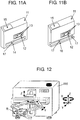
- FIG. 12 is a diagram illustrating an automatic power supply device of the related art. Since automatic power supply device 116 of the related art charges a moving body that is stopped at a distant position, automatic power supply device 116 includes a mechanism that carries out position correction for the purpose of realizing a contact between a power supply terminal and power receiving terminal 117 within a predetermined position error range.
- the moving body which is represented by an autonomous moving device, generally has a stop area in the vicinity of the autonomous moving device, in order to avoid collision with an obstacle.
- the autonomous moving device is stopped if the obstacle is detected in the stop area, and it is not possible to restart the autonomous moving device in a state where the obstacle is detected in the stop area. Therefore, in the moving body of the related art, the moving body is less likely to approach the automatic power supply device.
- the present disclosure solves the above problems relating to the related art, and provides an automatic power supply device and an autonomous moving system that enable to realize an approach of the moving body to the automatic power supply device, can make a drive unit of the automatic power supply device have a simple configuration, and enable to more effectively use a space during a power supply.
- an automatic power supply device that includes a terminal for a power supply, and supplies power to a battery which is placed in a moving body through a power receiver which is disposed in the moving body, the automatic power supply device including a drive mechanism that drives a power supplier including the terminal for a power supply, in which a cavity unit is included in a portion of a housing that forms the automatic power supply device.
- the automatic power supply device of the present invention it is possible to realize an approach of the moving body to the automatic power supply device, it is possible to make a drive unit of the automatic power supply device have a simple configuration, and it is possible to more effectively use a space during a power supply.
- autonomous moving device 1 includes environment information obtaining sensor 2, power receiver 5, rechargeable battery 6, and moving means 7.
- Environment information obtaining sensor 2 obtains position information of an obstacle which is present in a peripheral space of autonomous moving device 1.
- autonomous moving device 1 is driven by power which is supplied from rechargeable battery 6.
- Power receiver 5 obtains the power from automatic power supply device 11 illustrated in FIG. 3A and subsequent drawings, and supplies the power to rechargeable battery 6.
- moving means 7 is formed of wheels.
- Autonomous moving device 1 according to the exemplary embodiment is an example of a moving body.
- environment information obtaining sensor 2 obtains the information of measurement plane 3, which is in a plane substantially parallel to running surface R.
- a laser radar that scans a horizontal plane can be used.
- the laser radar is a distance sensor that obtains a distance to an object or an obstacle, in a forward semicircle-shaped obstacle detection area having a predetermined radius, by scanning a laser beam at a predetermined angle in a predetermined plane.
- the laser radar performs distance measurement per 0.5° in a range which is a measurement distance of 30m, and ⁇ 90° of left and right sides in an advancing direction.
- environment information obtaining sensor 2 intermittently performs scanning based on a fixed control period, and stores a set of distance data which is obtained per scanning of one time, as environment information (sensor information) in a storage unit (not illustrated) at each time point.
- FIG. 2 is a diagram illustrating a relationship between a disposition of autonomous moving device 1 and measurement plane 3 of environment information obtaining sensor 2, and is a diagram which is obtained by viewing autonomous moving device 1 from above.
- safety stop area 4 is set as an area for safely stopping autonomous moving device 1, in a portion of measurement plane 3 of environment information obtaining sensor 2.
- safety stop area 4 is set to 5 cm in the vicinity, from an outer periphery in the advancing direction of autonomous moving device 1.
- the configuration of the sensor and the example of the sensor described above are merely examples that realize the exemplary embodiment, and are not limited thereto, and it is possible to use various sensors.
- FIG. 3A and FIG. 3B are perspective views of automatic power supply device 11.
- FIG. 3A illustrates a state where power supplier 12 is stored within a housing of automatic power supply device 11
- FIG. 3B illustrates a state where power supplier 12 is out of the housing, in order to supply the power to autonomous moving device 1.
- Automatic power supply device 11 rectifies a power source which is supplied from the power source, and supplies the power to autonomous moving device 1 through power supplier 12.
- Power supplier 12 may be driven in a front direction and a rear direction, and has power supply terminal 13 for supplying the power.
- Power supplier 12 is stored in the housing in a standby state ( FIG. 3A ), and comes into contact with power receiver 5 of autonomous moving device 1, by being moved to the outside from the housing at the time of the power supply ( FIG. 3B ).
- Automatic power supply device 11 obtains timing of a charging start, and timing of a charging end, though communication.
- the communication may be directly performed between autonomous moving device 1 and automatic power supply device 11 by using optical communication, and for example, the communication may be a command from a central monitoring unit (not illustrated) that collectively controls autonomous moving device 1 and automatic power supply device 11.
- automatic power supply device 11 includes cavity unit 14 in a portion of the housing, and display unit 15.
- Cavity unit 14 is provided at a position having the same height as measurement plane 3 of autonomous moving device 1, and it is possible to use a rectangular shape as a simple shape.
- FIG. 4A and FIG. 4B an automatic power supply system according to the exemplary embodiment will be described, by using FIG. 4A and FIG. 4B .
- a position relationship between cavity unit 14 of automatic power supply device 11 and safety stop area 4 of autonomous moving device 1 will be described.
- FIG. 4A is a diagram which is obtained by viewing a state thereof from above, when autonomous moving device 1 is stopped at a power supply position ahead of automatic power supply device 11.
- FIG. 4B is a diagram which is obtained by viewing a state thereof from a side, when autonomous moving device 1 is stopped at the power supply position ahead of automatic power supply device 11.
- autonomous moving device 1 is stopped ahead of automatic power supply device 11, so as not to be in contact with automatic power supply device 11, and safety stop area 4 enters into cavity unit 14, but is not in contact with automatic power supply device 11.
- the autonomous moving device is not in contact with the automatic power supply device, ahead of automatic power supply device 11, and it is possible to prevent the autonomous moving device from stopping by detecting automatic power supply device 11 in the safety stop area.
- autonomous moving device 1 since autonomous moving device 1 may approach and may be stopped by automatic power supply device 11, it is possible to reduce a drive distance of power supplier 12, as power supplier 12 illustrated in FIG. 4B .
- FIG. 5 is a diagram which is obtained by viewing a state where autonomous moving device 1 is stopped for an automatic power supply ahead of automatic power supply device 11 from above.
- L1 indicates a depth of cavity unit 14
- L2 indicates a distance between autonomous moving device 1 and automatic power supply device 11 when autonomous moving device 1 arrives ahead of automatic power supply device 11
- L3 indicates a distance (range of safety stop area 4) which is from a tip of autonomous moving device 1 to a tip of safety stop area 4.
- L1, L2, and L3 are integers that satisfy the condition, for example, it is possible to set L1, L2, and L3 as follows.
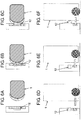
- FIG. 6A to FIG. 6C are diagrams which are obtained by viewing a connection between autonomous moving device 1 and automatic power supply device 11 from above
- FIG. 6D to FIG. 6F are diagrams which are obtained by viewing the connection from the side.
- FIG. 6A and FIG. 6D are diagrams illustrating a state when autonomous moving device 1 approaches automatic power supply device 11.
- FIG. 6B and FIG. 6E are diagrams illustrating a state when autonomous moving device 1 arrives ahead of automatic power supply device 11.
- FIG. 6C and FIG. 6F are diagrams illustrating a state when the automatic charging is carried out by pressing power supplier 12 against autonomous moving device 1 by a drive unit of automatic power supply device 11.
- an autonomous moving system of autonomous moving device 1 is also illustrated.
- FIG. 6A and FIG. 6D illustrated is a state where autonomous moving device 1 is moved towards a stop position ahead of automatic power supply device 11 while moving autonomous moving device 1 itself autonomously.
- Autonomous moving device 1 has a function of correcting an own position of autonomous moving device 1, by matching sensor data which is obtained by environment information obtaining sensor 2 with map information, in order to correct the own position thereof.
- Autonomous moving device 1 may correct the own position thereof, by using the shape of automatic power supply device 11, ahead of automatic power supply device 11.
- FIG. 7A is a diagram which is obtained by viewing a state where autonomous moving device 1 is stopped in front of automatic power supply device 11 from above autonomous moving device 1
- FIG. 7B is a diagram illustrating the shape of automatic power supply device 11 which is measured by using environment information obtaining sensor 2, when autonomous moving device 1 is stopped.
- edge 16 is provided in each of both ends of cavity unit 14 which is included in automatic power supply device 11.
- a width (that is, gap between edges 16 which are on both ends) of cavity unit 14 is smaller than a diameter of the obstacle detection area where environment information obtaining sensor 2 is included.
- FIG. 6B illustrates a state when autonomous moving device 1 arrives ahead of automatic power supply device 11.
- autonomous moving device 1 is stopped at the stop position, before the contact with automatic power supply device 11, and before safety stop area 4 of autonomous moving device 1 detects the housing of automatic power supply device 11.
- automatic power supply device 11 After autonomous moving device 1 arrives at automatic power supply device 11, automatic power supply device 11 obtains the arrival information through the communication, and drives power supplier 12, as illustrated in FIG. 6C , and presses power supply terminal 13 against power receiver 5 of autonomous moving device 1. Thereafter, automatic power supply device 11 starts the power supply, thereby, the power supply to rechargeable battery 6 of the autonomous moving device 1 from automatic power supply device 11 is realized.
- autonomous moving device 1 In a case where autonomous moving device 1 is separated from automatic power supply device 11, and starts the movement, autonomous moving device 1 starts the movement, by a flow which is contrary to the above description.
- automatic power supply device 11 obtains the movement start information through the communication, and stores power supplier 12 in the housing, after the obtaining. Thereafter, autonomous moving device 1 starts the movement, after confirming that power supplier 12 of automatic power supply device 11 is stored.
- safety stop area 4 may detect a portion of the housing of automatic power supply device 11, if autonomous moving device 1 performs a turning operation on the spot, after automatic power supply device 11 stores power supplier 12.
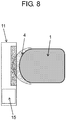
- FIG. 8 is a diagram which is obtained by viewing the disposition relationship between display unit 15 of automatic power supply device 11 and autonomous moving device 1 from above.
- Automatic power supply device 11 has several states such as a standby state, a charging state, or a stopping state. Display unit 15 is included, in order to notify an user of the state.
- autonomous moving device 1 is separated from display unit 15 and is stopped so that display unit 15 is in the position which is easily viewed by the user.
- autonomous moving device 1 is stopped on the right side with respect to the advancing direction of autonomous moving device 1, with respect to automatic power supply device 11.
- cavity unit 14 is not necessary in the vicinity of display unit 15, as illustrated in FIG. 8 , it is possible to make cavity unit 14 smaller.
- autonomous moving device 1 is used as a moving body, but it is possible to apply the moving body to other moving bodies including environment information obtaining sensor 2, regardless of autonomous moving device 1.
- the shape of cavity unit 14 is the rectangular shape, but the shape of cavity unit 14 may be various shapes. Another shape relating to cavity unit 14 will be described by using FIG. 9 , as a second exemplary embodiment.
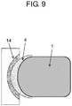
- FIG. 9 is a diagram which is obtaining by viewing the disposition of autonomous moving device 1 and automatic power supply device 11 at the time of the power supply of autonomous moving device 1 from above.
- a shape of cavity unit 14 a fan shape is substantially adopted.
- safety stop area 4 which is provided in the front-sided vicinity of autonomous moving device 1 has a fan shape
- by making the shape of cavity unit 14 on the side of automatic power supply device 11 the same shape it is possible to prevent that cavity unit 14 becomes too much large even in a case where safety stop area 4 of autonomous moving device 1 is set more largely.
- autonomous moving device 1 has a technology of correcting the own position of autonomous moving device 1 by using the shape of automatic power supply device 11.
- the technology in a case where autonomous moving device 1 is moved towards one specific automatic power supply device 11 from the plurality of automatic power supply devices 11, and in a case where automatic power supply devices 11 are set side by side, in autonomous moving device 1, since automatic power supply device 11 having a similar shape is present, there is possibility that the own position correction of autonomous moving device 1 is carried out by using erroneous automatic power supply device 11, and as a result, the erroneous own position correction thereof is carried out, and autonomous moving device 1 arrives ahead of erroneous automatic power supply device 11.
- Each of the plurality of automatic power supply devices 11 has cavity units 14 of which shapes are different from each other, thereby, it is possible to solve the problems described above.
- FIG. 10 is a diagram illustrating a case where autonomous moving device 1 causes a specific device to approach by selecting the specific device among automatic power supply devices 11a to 11c, and is a diagram which is obtained by viewing automatic power supply devices 11a to 11c from above.
- the autonomous moving system of autonomous moving device 1 is also illustrated.
- Automatic power supply device 11a includes cavity unit 14a having a rectangular shape.
- Automatic power supply device 11b includes cavity unit 14b having a fan shape.
- Automatic power supply device 11c includes cavity unit 14c having a stepped shape that is obtained by combining rectangular shapes of which sizes are different from each other.
- autonomous moving device 1 receives the power supply from only automatic power supply device 11a.
- Autonomous moving device 1 confirms the shapes of cavity units 14a to 14c in each of automatic power supply devices 11a to 11c, by using environment information obtaining sensor 2. Autonomous moving device 1 selects specific cavity unit 14a, and approaches automatic power supply device 11a.
- autonomous moving device 1 may approach by selecting predetermined automatic power supply device 11a.
- a shape of the cavity it is possible to use various shapes such as the rectangular shape, the fan shape, or the stepped shape that is obtained by combining the rectangular shapes of which sizes are different from each other described above.
- a portion of edge 16 may be replaced with protrusion 17, as illustrated in FIG. 11A .
- groove unit 18 may be used in place of cavity unit 14, and protrusion 17 may be provided at a position corresponding to edge 16.
- the autonomous power supply device facilitates the automatic power supply to the moving body which has a limitation on the approach to the object, such as the autonomous moving device having the safety stop area in the measurement area of the environment information obtaining sensor.
Landscapes
- Engineering & Computer Science (AREA)
- Power Engineering (AREA)
- Transportation (AREA)
- Mechanical Engineering (AREA)
- Automation & Control Theory (AREA)
- Aviation & Aerospace Engineering (AREA)
- Radar, Positioning & Navigation (AREA)
- Remote Sensing (AREA)
- Physics & Mathematics (AREA)
- General Physics & Mathematics (AREA)
- Sustainable Development (AREA)
- Sustainable Energy (AREA)
- Life Sciences & Earth Sciences (AREA)
- Charge And Discharge Circuits For Batteries Or The Like (AREA)
- Control Of Position, Course, Altitude, Or Attitude Of Moving Bodies (AREA)
- Electric Propulsion And Braking For Vehicles (AREA)
Applications Claiming Priority (2)
| Application Number | Priority Date | Filing Date | Title |
|---|---|---|---|
| JP2015050843 | 2015-03-13 | ||
| PCT/JP2016/000973 WO2016147571A1 (fr) | 2015-03-13 | 2016-02-24 | Système d'alimentation électrique automatique, dispositif d'alimentation électrique automatique, et système mobile autonome |
Publications (3)
| Publication Number | Publication Date |
|---|---|
| EP3240137A1 true EP3240137A1 (fr) | 2017-11-01 |
| EP3240137A4 EP3240137A4 (fr) | 2018-09-26 |
| EP3240137B1 EP3240137B1 (fr) | 2020-05-06 |
Family
ID=56919530
Family Applications (1)
| Application Number | Title | Priority Date | Filing Date |
|---|---|---|---|
| EP16764404.6A Active EP3240137B1 (fr) | 2015-03-13 | 2016-02-24 | Système d'alimentation électrique automatique, dispositif d'alimentation électrique automatique, et système mobile autonome |
Country Status (4)
| Country | Link |
|---|---|
| US (1) | US10023060B2 (fr) |
| EP (1) | EP3240137B1 (fr) |
| JP (1) | JP6123081B2 (fr) |
| WO (1) | WO2016147571A1 (fr) |
Cited By (1)
| Publication number | Priority date | Publication date | Assignee | Title |
|---|---|---|---|---|
| WO2022079369A1 (fr) * | 2020-10-16 | 2022-04-21 | Stanley Robotics | Système de recharge électrique autonome pour robot mobile extérieur |
Families Citing this family (2)
| Publication number | Priority date | Publication date | Assignee | Title |
|---|---|---|---|---|
| US10365656B2 (en) * | 2017-11-22 | 2019-07-30 | Locus Robotics Corp. | Robot charger docking localization |
| US11780340B2 (en) * | 2018-10-31 | 2023-10-10 | Hirschmann Automotive Gmbh | Method and apparatus for conductive charging |
Family Cites Families (13)
| Publication number | Priority date | Publication date | Assignee | Title |
|---|---|---|---|---|
| US4944357A (en) | 1989-04-27 | 1990-07-31 | Caterpillar Industrial Inc. | Power transferring arrangement |
| JPH033618A (ja) | 1989-05-30 | 1991-01-09 | Shinko Electric Co Ltd | 無人車のバッテリー自動充電装置 |
| JPH0515073A (ja) | 1991-06-28 | 1993-01-22 | Shinko Electric Co Ltd | 無人搬送車バツテリ−の自動充電用給電装置 |
| DE4344563C1 (de) | 1993-12-24 | 1994-12-08 | Daimler Benz Ag | Batterieladevorrichtung für ein Elektrofahrzeug |
| JP2920884B2 (ja) | 1997-05-27 | 1999-07-19 | 川崎重工業株式会社 | 無人誘導車両用充電装置 |
| US7332890B2 (en) * | 2004-01-21 | 2008-02-19 | Irobot Corporation | Autonomous robot auto-docking and energy management systems and methods |
| JP2006081310A (ja) | 2004-09-09 | 2006-03-23 | Matsushita Electric Works Ltd | 給電装置 |
| JP4442517B2 (ja) | 2005-06-07 | 2010-03-31 | パナソニック電工株式会社 | 非接触給電装置及び自律移動装置用給電システム |
| JP2009015611A (ja) | 2007-07-05 | 2009-01-22 | Figla Co Ltd | 充電システム、充電ユニットおよび移動ロボットの自動充電システム |
| JP4909930B2 (ja) * | 2008-03-28 | 2012-04-04 | 日立アプライアンス株式会社 | 自走式掃除システム |
| CN101607399A (zh) | 2008-06-19 | 2009-12-23 | 鸿富锦精密工业(深圳)有限公司 | 充电装置 |
| NL2007566C2 (en) | 2011-10-11 | 2013-04-15 | Lely Patent Nv | Vehicle system. |
| JP5949734B2 (ja) * | 2013-11-29 | 2016-07-13 | トヨタ自動車株式会社 | 異常判定システム、及びその判定方法 |
-
2016
- 2016-02-24 JP JP2016547197A patent/JP6123081B2/ja active Active
- 2016-02-24 US US15/549,665 patent/US10023060B2/en active Active
- 2016-02-24 WO PCT/JP2016/000973 patent/WO2016147571A1/fr not_active Ceased
- 2016-02-24 EP EP16764404.6A patent/EP3240137B1/fr active Active
Cited By (2)
| Publication number | Priority date | Publication date | Assignee | Title |
|---|---|---|---|---|
| WO2022079369A1 (fr) * | 2020-10-16 | 2022-04-21 | Stanley Robotics | Système de recharge électrique autonome pour robot mobile extérieur |
| FR3115241A1 (fr) * | 2020-10-16 | 2022-04-22 | Stanley Robotics | Système de recharge électrique autonome pour robot mobile extérieur. |
Also Published As
| Publication number | Publication date |
|---|---|
| US20180029487A1 (en) | 2018-02-01 |
| JPWO2016147571A1 (ja) | 2017-04-27 |
| EP3240137B1 (fr) | 2020-05-06 |
| US10023060B2 (en) | 2018-07-17 |
| WO2016147571A1 (fr) | 2016-09-22 |
| EP3240137A4 (fr) | 2018-09-26 |
| JP6123081B2 (ja) | 2017-05-10 |
Similar Documents
| Publication | Publication Date | Title |
|---|---|---|
| US11052781B2 (en) | Non-contact power supply system and power reception device | |
| US9187006B2 (en) | Vehicle positioning for wireless charging systems | |
| US20170083023A1 (en) | Apparatus for localizing cleaning robot, cleaning robot, and controlling method of cleaning robot | |
| JP4195894B2 (ja) | ドッキングシステム | |
| US9463706B2 (en) | Infrared triangulation method for locating vehicles for hands-free electric vehicle charging | |
| JP4442517B2 (ja) | 非接触給電装置及び自律移動装置用給電システム | |
| US10696167B2 (en) | Adjustable charging robot | |
| EP2556984A1 (fr) | Systeme d'assistance au parking pour véhicule permettant la recharge sans fil. | |
| US10551502B2 (en) | Positioning system for determining the position of a vehicle in a charging station | |
| CN108431713B (zh) | 用于给移动机器人充电的对接系统和方法 | |
| US20080174268A1 (en) | Automatic charging apparatus of autonomous mobile robot and automatic charging method using the same | |
| US9354634B2 (en) | Automatic homing and charging method for self-moving cleaning apparatus | |
| US20200257311A1 (en) | Cart having leading and following function | |
| US20150336462A1 (en) | Sonic triangulation method for locating vehicles for hands-free electric vehicle charging | |
| KR20160048347A (ko) | 이동로봇의 충전 스테이션 자동 도킹 시스템 및 그 방법 | |
| US10023060B2 (en) | Automatic power supply system, automatic power supply device, and autonomous moving system | |
| CN111166248A (zh) | 清洁机器人、自主充电方法及自主充电系统 | |
| JP2018025880A (ja) | 自律走行装置及び自律走行制御方法と制御プログラム | |
| JP2017015601A (ja) | 路面検知装置、移動体、路面検知方法、および路面検知プログラム | |
| CN114355889A (zh) | 控制方法、机器人、机器人充电座及计算机可读存储介质 | |
| US20180015837A1 (en) | Parking assistance device | |
| US20220236743A1 (en) | Power supply system and power supply device | |
| CN110495817B (zh) | 具有激光雷达的清洁设备回充对接方法及系统 | |
| JP2014014202A (ja) | 電力授受システム | |
| CN117519139A (zh) | 回充方法、移动机器人及存储介质 |
Legal Events
| Date | Code | Title | Description |
|---|---|---|---|
| STAA | Information on the status of an ep patent application or granted ep patent |
Free format text: STATUS: THE INTERNATIONAL PUBLICATION HAS BEEN MADE |
|
| PUAI | Public reference made under article 153(3) epc to a published international application that has entered the european phase |
Free format text: ORIGINAL CODE: 0009012 |
|
| STAA | Information on the status of an ep patent application or granted ep patent |
Free format text: STATUS: REQUEST FOR EXAMINATION WAS MADE |
|
| 17P | Request for examination filed |
Effective date: 20170728 |
|
| AK | Designated contracting states |
Kind code of ref document: A1 Designated state(s): AL AT BE BG CH CY CZ DE DK EE ES FI FR GB GR HR HU IE IS IT LI LT LU LV MC MK MT NL NO PL PT RO RS SE SI SK SM TR |
|
| AX | Request for extension of the european patent |
Extension state: BA ME |
|
| DAV | Request for validation of the european patent (deleted) | ||
| DAX | Request for extension of the european patent (deleted) | ||
| A4 | Supplementary search report drawn up and despatched |
Effective date: 20180827 |
|
| RIC1 | Information provided on ipc code assigned before grant |
Ipc: G05D 1/02 20060101ALI20180821BHEP Ipc: B60L 11/18 20060101ALI20180821BHEP Ipc: H02J 7/00 20060101AFI20180821BHEP |
|
| REG | Reference to a national code |
Ref country code: DE Ref legal event code: R079 Ref document number: 602016035884 Country of ref document: DE Free format text: PREVIOUS MAIN CLASS: H02J0007000000 Ipc: B60L0050500000 |
|
| STAA | Information on the status of an ep patent application or granted ep patent |
Free format text: STATUS: EXAMINATION IS IN PROGRESS |
|
| RIC1 | Information provided on ipc code assigned before grant |
Ipc: H02J 7/00 20060101ALI20190423BHEP Ipc: B60L 53/14 20190101ALI20190423BHEP Ipc: B60L 53/16 20190101ALI20190423BHEP Ipc: B60L 53/35 20190101ALI20190423BHEP Ipc: B60L 53/37 20190101ALI20190423BHEP Ipc: G05D 1/02 20060101ALI20190423BHEP Ipc: B60L 50/50 20190101AFI20190423BHEP Ipc: B60L 53/36 20190101ALI20190423BHEP |
|
| 17Q | First examination report despatched |
Effective date: 20190528 |
|
| GRAP | Despatch of communication of intention to grant a patent |
Free format text: ORIGINAL CODE: EPIDOSNIGR1 |
|
| STAA | Information on the status of an ep patent application or granted ep patent |
Free format text: STATUS: GRANT OF PATENT IS INTENDED |
|
| INTG | Intention to grant announced |
Effective date: 20191209 |
|
| GRAJ | Information related to disapproval of communication of intention to grant by the applicant or resumption of examination proceedings by the epo deleted |
Free format text: ORIGINAL CODE: EPIDOSDIGR1 |
|
| STAA | Information on the status of an ep patent application or granted ep patent |
Free format text: STATUS: EXAMINATION IS IN PROGRESS |
|
| GRAP | Despatch of communication of intention to grant a patent |
Free format text: ORIGINAL CODE: EPIDOSNIGR1 |
|
| STAA | Information on the status of an ep patent application or granted ep patent |
Free format text: STATUS: GRANT OF PATENT IS INTENDED |
|
| INTG | Intention to grant announced |
Effective date: 20200226 |
|
| GRAS | Grant fee paid |
Free format text: ORIGINAL CODE: EPIDOSNIGR3 |
|
| GRAA | (expected) grant |
Free format text: ORIGINAL CODE: 0009210 |
|
| STAA | Information on the status of an ep patent application or granted ep patent |
Free format text: STATUS: THE PATENT HAS BEEN GRANTED |
|
| AK | Designated contracting states |
Kind code of ref document: B1 Designated state(s): AL AT BE BG CH CY CZ DE DK EE ES FI FR GB GR HR HU IE IS IT LI LT LU LV MC MK MT NL NO PL PT RO RS SE SI SK SM TR |
|
| REG | Reference to a national code |
Ref country code: GB Ref legal event code: FG4D |
|
| REG | Reference to a national code |
Ref country code: AT Ref legal event code: REF Ref document number: 1266219 Country of ref document: AT Kind code of ref document: T Effective date: 20200515 Ref country code: CH Ref legal event code: EP |
|
| REG | Reference to a national code |
Ref country code: IE Ref legal event code: FG4D |
|
| REG | Reference to a national code |
Ref country code: DE Ref legal event code: R096 Ref document number: 602016035884 Country of ref document: DE |
|
| REG | Reference to a national code |
Ref country code: LT Ref legal event code: MG4D |
|
| REG | Reference to a national code |
Ref country code: NL Ref legal event code: MP Effective date: 20200506 |
|
| PG25 | Lapsed in a contracting state [announced via postgrant information from national office to epo] |
Ref country code: GR Free format text: LAPSE BECAUSE OF FAILURE TO SUBMIT A TRANSLATION OF THE DESCRIPTION OR TO PAY THE FEE WITHIN THE PRESCRIBED TIME-LIMIT Effective date: 20200807 Ref country code: NO Free format text: LAPSE BECAUSE OF FAILURE TO SUBMIT A TRANSLATION OF THE DESCRIPTION OR TO PAY THE FEE WITHIN THE PRESCRIBED TIME-LIMIT Effective date: 20200806 Ref country code: LT Free format text: LAPSE BECAUSE OF FAILURE TO SUBMIT A TRANSLATION OF THE DESCRIPTION OR TO PAY THE FEE WITHIN THE PRESCRIBED TIME-LIMIT Effective date: 20200506 Ref country code: SE Free format text: LAPSE BECAUSE OF FAILURE TO SUBMIT A TRANSLATION OF THE DESCRIPTION OR TO PAY THE FEE WITHIN THE PRESCRIBED TIME-LIMIT Effective date: 20200506 Ref country code: FI Free format text: LAPSE BECAUSE OF FAILURE TO SUBMIT A TRANSLATION OF THE DESCRIPTION OR TO PAY THE FEE WITHIN THE PRESCRIBED TIME-LIMIT Effective date: 20200506 Ref country code: IS Free format text: LAPSE BECAUSE OF FAILURE TO SUBMIT A TRANSLATION OF THE DESCRIPTION OR TO PAY THE FEE WITHIN THE PRESCRIBED TIME-LIMIT Effective date: 20200906 Ref country code: PT Free format text: LAPSE BECAUSE OF FAILURE TO SUBMIT A TRANSLATION OF THE DESCRIPTION OR TO PAY THE FEE WITHIN THE PRESCRIBED TIME-LIMIT Effective date: 20200907 |
|
| PG25 | Lapsed in a contracting state [announced via postgrant information from national office to epo] |
Ref country code: LV Free format text: LAPSE BECAUSE OF FAILURE TO SUBMIT A TRANSLATION OF THE DESCRIPTION OR TO PAY THE FEE WITHIN THE PRESCRIBED TIME-LIMIT Effective date: 20200506 Ref country code: HR Free format text: LAPSE BECAUSE OF FAILURE TO SUBMIT A TRANSLATION OF THE DESCRIPTION OR TO PAY THE FEE WITHIN THE PRESCRIBED TIME-LIMIT Effective date: 20200506 Ref country code: RS Free format text: LAPSE BECAUSE OF FAILURE TO SUBMIT A TRANSLATION OF THE DESCRIPTION OR TO PAY THE FEE WITHIN THE PRESCRIBED TIME-LIMIT Effective date: 20200506 Ref country code: BG Free format text: LAPSE BECAUSE OF FAILURE TO SUBMIT A TRANSLATION OF THE DESCRIPTION OR TO PAY THE FEE WITHIN THE PRESCRIBED TIME-LIMIT Effective date: 20200806 |
|
| REG | Reference to a national code |
Ref country code: AT Ref legal event code: MK05 Ref document number: 1266219 Country of ref document: AT Kind code of ref document: T Effective date: 20200506 |
|
| PG25 | Lapsed in a contracting state [announced via postgrant information from national office to epo] |
Ref country code: NL Free format text: LAPSE BECAUSE OF FAILURE TO SUBMIT A TRANSLATION OF THE DESCRIPTION OR TO PAY THE FEE WITHIN THE PRESCRIBED TIME-LIMIT Effective date: 20200506 Ref country code: AL Free format text: LAPSE BECAUSE OF FAILURE TO SUBMIT A TRANSLATION OF THE DESCRIPTION OR TO PAY THE FEE WITHIN THE PRESCRIBED TIME-LIMIT Effective date: 20200506 |
|
| PG25 | Lapsed in a contracting state [announced via postgrant information from national office to epo] |
Ref country code: CZ Free format text: LAPSE BECAUSE OF FAILURE TO SUBMIT A TRANSLATION OF THE DESCRIPTION OR TO PAY THE FEE WITHIN THE PRESCRIBED TIME-LIMIT Effective date: 20200506 Ref country code: IT Free format text: LAPSE BECAUSE OF FAILURE TO SUBMIT A TRANSLATION OF THE DESCRIPTION OR TO PAY THE FEE WITHIN THE PRESCRIBED TIME-LIMIT Effective date: 20200506 Ref country code: RO Free format text: LAPSE BECAUSE OF FAILURE TO SUBMIT A TRANSLATION OF THE DESCRIPTION OR TO PAY THE FEE WITHIN THE PRESCRIBED TIME-LIMIT Effective date: 20200506 Ref country code: SM Free format text: LAPSE BECAUSE OF FAILURE TO SUBMIT A TRANSLATION OF THE DESCRIPTION OR TO PAY THE FEE WITHIN THE PRESCRIBED TIME-LIMIT Effective date: 20200506 Ref country code: EE Free format text: LAPSE BECAUSE OF FAILURE TO SUBMIT A TRANSLATION OF THE DESCRIPTION OR TO PAY THE FEE WITHIN THE PRESCRIBED TIME-LIMIT Effective date: 20200506 Ref country code: ES Free format text: LAPSE BECAUSE OF FAILURE TO SUBMIT A TRANSLATION OF THE DESCRIPTION OR TO PAY THE FEE WITHIN THE PRESCRIBED TIME-LIMIT Effective date: 20200506 Ref country code: DK Free format text: LAPSE BECAUSE OF FAILURE TO SUBMIT A TRANSLATION OF THE DESCRIPTION OR TO PAY THE FEE WITHIN THE PRESCRIBED TIME-LIMIT Effective date: 20200506 Ref country code: AT Free format text: LAPSE BECAUSE OF FAILURE TO SUBMIT A TRANSLATION OF THE DESCRIPTION OR TO PAY THE FEE WITHIN THE PRESCRIBED TIME-LIMIT Effective date: 20200506 |
|
| REG | Reference to a national code |
Ref country code: DE Ref legal event code: R097 Ref document number: 602016035884 Country of ref document: DE |
|
| PG25 | Lapsed in a contracting state [announced via postgrant information from national office to epo] |
Ref country code: PL Free format text: LAPSE BECAUSE OF FAILURE TO SUBMIT A TRANSLATION OF THE DESCRIPTION OR TO PAY THE FEE WITHIN THE PRESCRIBED TIME-LIMIT Effective date: 20200506 Ref country code: SK Free format text: LAPSE BECAUSE OF FAILURE TO SUBMIT A TRANSLATION OF THE DESCRIPTION OR TO PAY THE FEE WITHIN THE PRESCRIBED TIME-LIMIT Effective date: 20200506 |
|
| PLBE | No opposition filed within time limit |
Free format text: ORIGINAL CODE: 0009261 |
|
| STAA | Information on the status of an ep patent application or granted ep patent |
Free format text: STATUS: NO OPPOSITION FILED WITHIN TIME LIMIT |
|
| 26N | No opposition filed |
Effective date: 20210209 |
|
| PG25 | Lapsed in a contracting state [announced via postgrant information from national office to epo] |
Ref country code: SI Free format text: LAPSE BECAUSE OF FAILURE TO SUBMIT A TRANSLATION OF THE DESCRIPTION OR TO PAY THE FEE WITHIN THE PRESCRIBED TIME-LIMIT Effective date: 20200506 |
|
| PG25 | Lapsed in a contracting state [announced via postgrant information from national office to epo] |
Ref country code: MC Free format text: LAPSE BECAUSE OF FAILURE TO SUBMIT A TRANSLATION OF THE DESCRIPTION OR TO PAY THE FEE WITHIN THE PRESCRIBED TIME-LIMIT Effective date: 20200506 |
|
| REG | Reference to a national code |
Ref country code: BE Ref legal event code: MM Effective date: 20210228 |
|
| PG25 | Lapsed in a contracting state [announced via postgrant information from national office to epo] |
Ref country code: LU Free format text: LAPSE BECAUSE OF NON-PAYMENT OF DUE FEES Effective date: 20210224 Ref country code: LI Free format text: LAPSE BECAUSE OF NON-PAYMENT OF DUE FEES Effective date: 20210228 Ref country code: CH Free format text: LAPSE BECAUSE OF NON-PAYMENT OF DUE FEES Effective date: 20210228 |
|
| PG25 | Lapsed in a contracting state [announced via postgrant information from national office to epo] |
Ref country code: IE Free format text: LAPSE BECAUSE OF NON-PAYMENT OF DUE FEES Effective date: 20210224 |
|
| PG25 | Lapsed in a contracting state [announced via postgrant information from national office to epo] |
Ref country code: BE Free format text: LAPSE BECAUSE OF NON-PAYMENT OF DUE FEES Effective date: 20210228 |
|
| PG25 | Lapsed in a contracting state [announced via postgrant information from national office to epo] |
Ref country code: HU Free format text: LAPSE BECAUSE OF FAILURE TO SUBMIT A TRANSLATION OF THE DESCRIPTION OR TO PAY THE FEE WITHIN THE PRESCRIBED TIME-LIMIT; INVALID AB INITIO Effective date: 20160224 |
|
| PG25 | Lapsed in a contracting state [announced via postgrant information from national office to epo] |
Ref country code: CY Free format text: LAPSE BECAUSE OF FAILURE TO SUBMIT A TRANSLATION OF THE DESCRIPTION OR TO PAY THE FEE WITHIN THE PRESCRIBED TIME-LIMIT Effective date: 20200506 |
|
| PG25 | Lapsed in a contracting state [announced via postgrant information from national office to epo] |
Ref country code: MK Free format text: LAPSE BECAUSE OF FAILURE TO SUBMIT A TRANSLATION OF THE DESCRIPTION OR TO PAY THE FEE WITHIN THE PRESCRIBED TIME-LIMIT Effective date: 20200506 |
|
| PG25 | Lapsed in a contracting state [announced via postgrant information from national office to epo] |
Ref country code: TR Free format text: LAPSE BECAUSE OF FAILURE TO SUBMIT A TRANSLATION OF THE DESCRIPTION OR TO PAY THE FEE WITHIN THE PRESCRIBED TIME-LIMIT Effective date: 20200506 |
|
| PG25 | Lapsed in a contracting state [announced via postgrant information from national office to epo] |
Ref country code: MT Free format text: LAPSE BECAUSE OF FAILURE TO SUBMIT A TRANSLATION OF THE DESCRIPTION OR TO PAY THE FEE WITHIN THE PRESCRIBED TIME-LIMIT Effective date: 20200506 |
|
| PGFP | Annual fee paid to national office [announced via postgrant information from national office to epo] |
Ref country code: DE Payment date: 20250218 Year of fee payment: 10 |
|
| PGFP | Annual fee paid to national office [announced via postgrant information from national office to epo] |
Ref country code: FR Payment date: 20250221 Year of fee payment: 10 |
|
| PGFP | Annual fee paid to national office [announced via postgrant information from national office to epo] |
Ref country code: GB Payment date: 20250220 Year of fee payment: 10 |