EP3240159A1 - Elektrische anschlussschiene zum austausch von elektrischer energie zwischen einem elektrischen gerät und einem stromnetz - Google Patents
Elektrische anschlussschiene zum austausch von elektrischer energie zwischen einem elektrischen gerät und einem stromnetz Download PDFInfo
- Publication number
- EP3240159A1 EP3240159A1 EP17168111.7A EP17168111A EP3240159A1 EP 3240159 A1 EP3240159 A1 EP 3240159A1 EP 17168111 A EP17168111 A EP 17168111A EP 3240159 A1 EP3240159 A1 EP 3240159A1
- Authority
- EP
- European Patent Office
- Prior art keywords
- electrical
- component
- zone
- connection bar
- power
- Prior art date
- Legal status (The legal status is an assumption and is not a legal conclusion. Google has not performed a legal analysis and makes no representation as to the accuracy of the status listed.)
- Granted
Links
Images


Classifications
-
- H—ELECTRICITY
- H02—GENERATION; CONVERSION OR DISTRIBUTION OF ELECTRIC POWER
- H02K—DYNAMO-ELECTRIC MACHINES
- H02K11/00—Structural association of dynamo-electric machines with electric components or with devices for shielding, monitoring or protection
- H02K11/30—Structural association with control circuits or drive circuits
- H02K11/33—Drive circuits, e.g. power electronics
-
- H—ELECTRICITY
- H02—GENERATION; CONVERSION OR DISTRIBUTION OF ELECTRIC POWER
- H02K—DYNAMO-ELECTRIC MACHINES
- H02K11/00—Structural association of dynamo-electric machines with electric components or with devices for shielding, monitoring or protection
- H02K11/0094—Structural association with other electrical or electronic devices
-
- H—ELECTRICITY
- H02—GENERATION; CONVERSION OR DISTRIBUTION OF ELECTRIC POWER
- H02K—DYNAMO-ELECTRIC MACHINES
- H02K5/00—Casings; Enclosures; Supports
- H02K5/04—Casings or enclosures characterised by the shape, form or construction thereof
- H02K5/22—Auxiliary parts of casings not covered by groups H02K5/06-H02K5/20, e.g. shaped to form connection boxes or terminal boxes
- H02K5/225—Terminal boxes or connection arrangements
-
- H—ELECTRICITY
- H02—GENERATION; CONVERSION OR DISTRIBUTION OF ELECTRIC POWER
- H02K—DYNAMO-ELECTRIC MACHINES
- H02K9/00—Arrangements for cooling or ventilating
- H02K9/22—Arrangements for cooling or ventilating by solid heat conducting material embedded in, or arranged in contact with, the stator or rotor, e.g. heat bridges
- H02K9/227—Heat sinks
-
- H—ELECTRICITY
- H05—ELECTRIC TECHNIQUES NOT OTHERWISE PROVIDED FOR
- H05K—PRINTED CIRCUITS; CASINGS OR CONSTRUCTIONAL DETAILS OF ELECTRIC APPARATUS; MANUFACTURE OF ASSEMBLAGES OF ELECTRICAL COMPONENTS
- H05K7/00—Constructional details common to different types of electric apparatus
- H05K7/14—Mounting supporting structure in casing or on frame or rack
- H05K7/1422—Printed circuit boards receptacles, e.g. stacked structures, electronic circuit modules or box like frames
- H05K7/1427—Housings
- H05K7/1432—Housings specially adapted for power drive units or power converters
- H05K7/14329—Housings specially adapted for power drive units or power converters specially adapted for the configuration of power bus bars
Definitions
- the invention relates to an electrical connection bar for exchanging electrical energy between an electrical equipment and an electrical network.
- the invention also relates to an electrical device comprising an electrical connection bar according to the invention, a voltage converter comprising an electrical device according to the invention, an electrical equipment comprising a voltage converter according to the invention, and a supercharger.
- electrical apparatus comprising electrical equipment according to the invention.
- an electric motor especially for a motor vehicle, is powered by electronic power modules.
- an electronic power module is supplied with electrical energy by an electrical connection bar.
- An electrical connection bar includes power traces intended to be electrically connected to a source of electrical energy, so as to supply electrical power to the electronic power modules.
- the electrical connection bar also comprises filtering components, for example an inductor and capacitors, so as to filter the electrical energy intended to supply the electronic power modules.
- connection bars comprising an inductor arranged in a housing.
- the case of the inductor is usually bulky, which has the disadvantage of increasing the size of the electrical connection bar.
- connection bars comprising an inductance mounted bare on the electrical connection bar, that is to say arranged without a box on the electrical connection bar.
- the inductor is generally soldered to the power traces of the electrical connection bar.
- the inductor being mounted bare on the electrical connection bar, it is not protected during the welding operation, and can be reached by welding, outside the connection area with said electrical connection bar .
- such an inductor is generally bonded to the electrical connection bar so as to be mechanically fixed, which increases the costs and production times of such an electrical connection bar.
- the present invention aims to overcome the disadvantages of the prior art by providing an electrical connection bar for good mechanical strength of the inductor, without increasing the size of the device.
- a power trace is for example an electrically conductive part, in particular a metal part, for example copper, said part being able to be a metal blade, or a metal bar.
- connection and reception zones of the electrical connection bar protects the electrical component during the electrical connection of the latter to the first and second power traces.
- the electrical connection bar according to the invention makes it possible to reduce the size of the electrical connection bar, in particular by eliminating the case of the electrical component, while guaranteeing good mechanical strength of said electrical component on the connection bar. electric.
- the electrical device according to the invention allows a reduction of costs and production times, in particular by removing the case and by removing the bonding step of the electrical component on the electrical connection bar.
- connection and reception areas allows protection of the electrical component during the electrical connection of the latter to the electrical connection bar.
- a voltage converter according to the invention allows efficient cooling of the inductance of the electrical connection bar, and thus allows efficient evacuation of the heat generated by the electrical device.
- a thermally conductive material can fill the space between the electrical component and said cavity.
- the invention also relates to an electrical equipment comprising an electric machine and a voltage converter according to the invention, wherein the voltage converter is mounted on the electric machine.
- the invention also relates to an electric supercharger, particularly for a motor vehicle, comprising an electrical equipment according to the invention.
- the invention relates to an electrical connection bar for exchanging energy between an electrical equipment, in particular embedded in a motor vehicle, and an electrical network.
- the electrical network is, for example, an electrical network of the motor vehicle, including an electrical network powered by a voltage of + 48V.
- the electrical network is a network of continuous electrical energy.
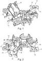
- Such an electrical connection bar 10 is represented on the Figures 1 and 2 .
- the electrical connection bar 10 comprises at least one trace of power.
- a trace of power is an electrically conductive trace, especially metal, for example copper.
- a power trace may be a metal blade, or a metal bar.
- a power trace is intended to transmit a current between the electrical network and the electrical equipment.
- the electrical connection bar 10 comprises a positive power trace 12 and a negative power trace 14.
- the polarities may be reversed, for example the referenced power trace 12 may be negative and the referenced power trace 14 may be positive.
- the positive power trace 12 is in particular intended to be electrically connected to a pole of positive polarity of the electrical network, for example at an electrical voltage of + 48V.
- the negative power trace 14 is in particular intended to be electrically connected to a pole of negative polarity of the electrical network, for example at an electrical voltage of 0V.
- the power traces 12, 14 are also intended to be electrically connected to at least one electrical component, for example to a filtering component.
- the filtering component may be, for example, an inductor or a capacitor.
- inductance is meant any electronic component intended by its construction to have a certain value of inductance.
- an inductor may designate a coil, or a solenoid.
- the electrical connection bar 10 may also comprise two power traces 13, 15, intended to be electrically connected to the power tracks 12, 14. More specifically, the power traces 13, 15 are intended to be electrically connected to the filtering component. , the filtering component being intended to be electrically connected to the power tracks 12, 14.
- the power traces 12, 13, 14, 15 respectively comprise terminals B, D, A, C, represented on the figure 3 , intended to be connected to electrical elements external to the electrical connection bar 10.
- the power traces 12, 14 are distinct from each other and are partially overmolded electrically insulating material, for example plastic material.
- the overmolding 16 of the traces of power 12, 14 is visible on the Figures 1 and 2 , and the power traces 12, 14 shown without overmolding are visible on the figure 3 .
- the electrical connection bar 10 comprises a reception zone 18, in particular visible on the figure 2 , shaped to receive an electrical component.
- the overmolding 16 of the power traces 12, 14 may comprise the reception zone 18.
- the electrical component can be mounted in force in the receiving zone 18.
- the receiving zone 18 can be shaped to receive the electric component without play.
- the reception of the filtering component in force in the reception zone makes it possible to ensure good mechanical strength of the electrical component in the reception zone.
- the electrical connection bar 10 also comprises a connection zone 20, in particular visible on the figure 1 .
- the power traces are intended to be electrically connected to the electrical component.
- connection zone 20 can be formed in the overmolding 16 of the power traces.
- the receiving zone 18 and the connection zone 20 are separated by the overmoulding 16.
- the overmolding 16 of the power tracks 12, 14 may comprise an upper surface, represented in FIG. figure 1 , comprising the connection zone 20, and a lower face, represented in figure 2 , comprising the reception zone 18.
- the electrical component can be mounted bare, that is to say without a box, to reduce the size of said electrical component, and therefore to reduce the size of the receiving area, and therefore the dimensions of the bar electrical connection.
- connection zone separated from the receiving zone by overmolding allows protection of the electrical component during the electrical connection of the latter to power traces.
- the overmolding prevents the metal projections generated during the electrical connection of the electrical component to the power traces, in particular by electric welding.
- the receiving zone 18 may comprise a wall 22 forming the bottom of said receiving zone 18, and a wall 24 extending from said bottom in a substantially transverse direction, in particular in a substantially perpendicular direction, relative to said bottom.
- the wall 24, referred to as the lateral wall, can extend continuously around the reception zone 18.
- the wall 24 may have a height of between 50% and 75% of the height of the electrical component.
- Such a wall advantageously protects and mechanically maintain the electrical component.
- the invention also relates to an electrical device comprising a connection bar as described above.
- FIGS 4 and 5 represent an electrical device 100 according to the invention comprising an electrical connection bar 10 according to the invention and an electrical component 110.
- the electrical component will be illustrated in the figures by an inductor.
- the inductance is received in the reception zone 18 of the electrical connection bar 10.
- the terminals 112 of the inductor are electrically connected to the power traces in the connection zone 20 of the electrical connection bar 10.
- terminals 112 of the electrical component can be soldered in the connection zone 20 of the electrical connection bar 10.
- the electrical component 110 received in the receiving zone 18 is devoid of housing.
- the overmolding and more precisely the bottom of the receiving zone 18, comprises through orifices 114 in which the connection terminals 112 of the inductor are received.
- the through holes allow the electrical connection of the connection terminals of the electrical component to the power traces.
- connection terminals of the electrical component in the through orifices makes it possible to guarantee a good mechanical strength of the electrical component in the reception zone.
- the mechanical holding of the electrical component in the receiving zone is devoid of fixing element, such as glue.
- the electrical connection bar 10, and more precisely the overmoulding 16, may comprise guiding elements 26 of the connection terminals of the electrical component intended to be electrically connected to the power traces.
- the guiding elements 26 make it possible to refocus the connection terminals of the electrical component with a view to their electrical connection to the power traces, and thus to correctly connect the electrical component to the power traces, without damaging the electrical component.
- the section of the guide orifices at the receiving zone of the electrical component is larger than the section of the guide orifices at the connection zone.
- the power traces 12, 14 may also comprise, in a zone devoid of overmolding, connection terminals configured to allow electrical connection with electrical elements.
- the electrical elements may be filtering components, such as capacitors, as shown in FIGS. Figures 6 and 7 .
- connection terminals 130 of the power traces are electrically connected to an electrical element 120.
- the electrical element 120 here a connecting capacitor, may comprise a central pin 122 associated with a peripheral pin 124.
- connection terminals 130 of the power traces are electrically connected to an electrical element 140.
- the electrical element 140 comprises two pins 132 arranged substantially symmetrically with respect to the center of the base of the electrical component, the pins 132 and the center of the base being substantially aligned.
- the invention also relates to an electric supercharger, particularly for a motor vehicle, comprising an electrical equipment.
- the electrical equipment includes an electric machine and a voltage converter.
- the voltage converter is mounted on the electric machine.
- the voltage converter is for controlling electrical energy exchanged between the electrical machine and a power source.
- the voltage converter comprises the electrical device as described above, and a heat sink configured to cool the voltage converter.
- a section of such a voltage converter 200 is for example illustrated in figure 8 .
- a wall of the heat sink 210 is disposed opposite the electrical device 100, in particular vis-à-vis the receiving area 18 of the bar electrical connection 10 so that at least a portion of the electrical component 110 is received in a cavity 220 of said wall of the heat sink 210.
- the height of the wall 24 of the reception zone 18 greater than or equal to half the height of the inductor and less than 75% of the height of said inductor allows efficient cooling of said inductor, while ensuring its mechanical maintenance.
- a wall height less than 75% of the height of the electrical component allows the electrical component to come into contact with the cooling surface of the heat sink, and a wall height greater than 50% of the height of the electrical component allows to maintain the mechanical component of said electrical component.
- the receiving area 18 may include an aperture configured to allow reception of the electrical component in said receiving area.
- this opening allows efficient cooling of the electrical component.
- a thermally conductive material can fill the gap between the electrical component and the cavity 220 of the heat sink 210.
- the thermally conductive material can be a gel, a resin or an adhesive.
- the cavity 220 of the heat sink filled with thermally conductive material allows an effective heat dissipation of the heat generated by the electrical component of the electrical device.
- the figures 9 and 10 illustrate an example of an electric supercharger 300 comprising the voltage converter 200 and the electrical machine 320, in particular a rotating electrical machine.
- the electric supercharger 300 is configured to be embedded in a vehicle for compressing the intake gases of the combustion engine of the vehicle.
- the electrical network is an electrical network of the vehicle and includes a battery supplying said electrical network.
- the supercharger 300 comprises a compression wheel 310 for compressing the intake air of a combustion engine. association of which the electric supercharger 300 is mounted.
- the compression wheel 310 is rotated by the electric machine 320.
- the supercharging compressor 300 may comprise a housing 330 which comprises the compression wheel 310, the electrical machine 320 and the voltage converter 200. This case 330 may be in several parts that are mounted on each other to form the case 330.
- the electrical device 100 can be mounted on a surface 115.
- This surface 115 is in particular perpendicular to the axis of rotation ⁇ of the electrical machine 320.
- the surface 115 of support can be a face a wall separating two housings from the housing 330.
- the support surface 115 may be a face of a wall 331 separating a housing from the housing 330 comprising the voltage converter 200 of another housing comprising the electrical machine 320.
- the electrical device 100 is in particular electrically connected to electronic components (not shown) which control the energy exchanged with the electrical machine 320, to supply these electronic components.
- the electronic device 100 can be connected to these electronic components via terminals A, B, in particular represented on the figures 3 and 10 , located downstream of the electrical component 110 described above.
- the upstream-downstream direction corresponding to a direction from the electrical network to the load to which the electrical device 100 is connected.
- the electrical device 100 is notably connected to the electrical network by terminals C, D, in particular represented on the Figures 3 and 8 , located upstream of the electrical component 110 described above.
- the electrical machine 320 is in particular between the voltage converter 200 and the compression wheel 310.
- the voltage converter 200 is thus placed at an axial end of the electric supercharger 300.
- a cover can come close the voltage converter 200
- the electrical machine 320 can be positioned along the axis of rotation ⁇ between the voltage converter 200 and the compression wheel 310, that is to say between a corresponding axial zone. to the voltage converter 200 and an axial zone corresponding to the compression wheel 310.
- the arrangement of the compression wheel 310, the electrical machine 320 and the 200 voltage converter can be different.
- the voltage converter 200 may be placed between the electric machine 320 and the compression wheel 310.
- the invention also relates to a method of assembling an electrical device according to the invention.
- the assembly method comprises a step of providing an electrical connection bar as described above, and at least one electrical element.
- the supplied electrical connection bar has a receiving area and a connection area.
- the electrical element is, for example, an inductor without housing.
- the assembly method comprises a step of inserting the electrical component into the receiving zone. More specifically, the connection terminals of the electrical component are inserted into the corresponding through holes of the overmoulding. The connection terminals of the electrical component can be forcefully inserted into the through holes.
- the assembly method comprises a connection step, during which the connection terminals of the electrical component are electrically connected to the power traces.
- the connection step can be performed by welding.
Landscapes
- Engineering & Computer Science (AREA)
- Power Engineering (AREA)
- Microelectronics & Electronic Packaging (AREA)
- Coils Or Transformers For Communication (AREA)
Applications Claiming Priority (1)
| Application Number | Priority Date | Filing Date | Title |
|---|---|---|---|
| FR1653782A FR3050878B1 (fr) | 2016-04-28 | 2016-04-28 | Barre de connexion electrique destinee a echanger de l'energie electrique entre un equipement electrique et un reseau electrique |
Publications (2)
| Publication Number | Publication Date |
|---|---|
| EP3240159A1 true EP3240159A1 (de) | 2017-11-01 |
| EP3240159B1 EP3240159B1 (de) | 2025-05-21 |
Family
ID=56119659
Family Applications (1)
| Application Number | Title | Priority Date | Filing Date |
|---|---|---|---|
| EP17168111.7A Active EP3240159B1 (de) | 2016-04-28 | 2017-04-26 | Elektrische anschlussschiene zum austausch von elektrischer energie zwischen einem elektrischen gerät und einem stromnetz |
Country Status (2)
| Country | Link |
|---|---|
| EP (1) | EP3240159B1 (de) |
| FR (1) | FR3050878B1 (de) |
Cited By (4)
| Publication number | Priority date | Publication date | Assignee | Title |
|---|---|---|---|---|
| WO2019122283A1 (fr) * | 2017-12-22 | 2019-06-27 | Valeo Siemens Eautomotive France Sas | Barre de connexion electrique pour ensemble electrique |
| IT201800007376A1 (it) * | 2018-07-20 | 2020-01-20 | Caricabatterie per veicoli e relativo procedimento di realizzazione | |
| WO2021043727A1 (fr) * | 2019-09-06 | 2021-03-11 | Valeo Siemens Eautomotive France Sas | Ensemble d'une carte, d'un composant electrique et d'un connecteur electrique |
| WO2024200920A1 (fr) * | 2023-03-27 | 2024-10-03 | Nidec Psa Emotors | Barre de conduction électrique |
Citations (4)
| Publication number | Priority date | Publication date | Assignee | Title |
|---|---|---|---|---|
| EP2206922A1 (de) * | 2007-11-06 | 2010-07-14 | Mitsubishi Heavy Industries, Ltd. | Elektrischer kompressor mit integriertem umrichter |
| US20110163705A1 (en) * | 2009-02-10 | 2011-07-07 | Mitsubishi Heavy Industries, Ltd. | Inverter and integrated-inverter electric compressor |
| WO2016009133A1 (fr) * | 2014-07-15 | 2016-01-21 | Valeo Equipements Electriques Moteur | Convertisseur de puissance de courant continu en courant alternatif |
| WO2016012666A1 (fr) * | 2014-07-23 | 2016-01-28 | Valeo Equipements Electriques Moteur | Compresseur de suralimentation électrique |
-
2016
- 2016-04-28 FR FR1653782A patent/FR3050878B1/fr active Active
-
2017
- 2017-04-26 EP EP17168111.7A patent/EP3240159B1/de active Active
Patent Citations (4)
| Publication number | Priority date | Publication date | Assignee | Title |
|---|---|---|---|---|
| EP2206922A1 (de) * | 2007-11-06 | 2010-07-14 | Mitsubishi Heavy Industries, Ltd. | Elektrischer kompressor mit integriertem umrichter |
| US20110163705A1 (en) * | 2009-02-10 | 2011-07-07 | Mitsubishi Heavy Industries, Ltd. | Inverter and integrated-inverter electric compressor |
| WO2016009133A1 (fr) * | 2014-07-15 | 2016-01-21 | Valeo Equipements Electriques Moteur | Convertisseur de puissance de courant continu en courant alternatif |
| WO2016012666A1 (fr) * | 2014-07-23 | 2016-01-28 | Valeo Equipements Electriques Moteur | Compresseur de suralimentation électrique |
Cited By (12)
| Publication number | Priority date | Publication date | Assignee | Title |
|---|---|---|---|---|
| WO2019122283A1 (fr) * | 2017-12-22 | 2019-06-27 | Valeo Siemens Eautomotive France Sas | Barre de connexion electrique pour ensemble electrique |
| FR3076099A1 (fr) * | 2017-12-22 | 2019-06-28 | Valeo Siemens Eautomotive France Sas | Barre de connexion electrique pour ensemble electrique |
| CN111511606A (zh) * | 2017-12-22 | 2020-08-07 | 维洛西门子新能源汽车法国简式股份公司 | 用于电组件的电连接条 |
| CN111511606B (zh) * | 2017-12-22 | 2024-04-26 | 维洛西门子新能源汽车法国简式股份公司 | 电组件及用于电组件的电母线条 |
| IT201800007376A1 (it) * | 2018-07-20 | 2020-01-20 | Caricabatterie per veicoli e relativo procedimento di realizzazione | |
| WO2020016802A1 (en) * | 2018-07-20 | 2020-01-23 | Meta System S.P.A. | Battery charger for vehicles and relative realization process |
| CN110733360A (zh) * | 2018-07-20 | 2020-01-31 | 美达系统有限公司 | 用于车辆的电池充电器和相关的实现过程 |
| US11999249B2 (en) | 2018-07-20 | 2024-06-04 | Meta System S.P.A. | Battery charger for vehicles and relative realization process |
| WO2021043727A1 (fr) * | 2019-09-06 | 2021-03-11 | Valeo Siemens Eautomotive France Sas | Ensemble d'une carte, d'un composant electrique et d'un connecteur electrique |
| FR3100672A1 (fr) * | 2019-09-06 | 2021-03-12 | Valeo Siemens Eautomotive France Sas | Ensemble d’une carte, d’un composant électrique et d’un connecteur électrique |
| WO2024200920A1 (fr) * | 2023-03-27 | 2024-10-03 | Nidec Psa Emotors | Barre de conduction électrique |
| FR3147447A1 (fr) * | 2023-03-27 | 2024-10-04 | Nidec Psa Emotors | Barre de conduction électrique |
Also Published As
| Publication number | Publication date |
|---|---|
| FR3050878A1 (fr) | 2017-11-03 |
| EP3240159B1 (de) | 2025-05-21 |
| FR3050878B1 (fr) | 2019-11-22 |
Similar Documents
| Publication | Publication Date | Title |
|---|---|---|
| EP1886401B1 (de) | Elektronikmodul für eine elektrische drehmaschine | |
| EP3176918B1 (de) | Elektronischer aufbau zur stromversorgung einer elektrischen maschine für ein kraftfahrzeug | |
| EP3240159B1 (de) | Elektrische anschlussschiene zum austausch von elektrischer energie zwischen einem elektrischen gerät und einem stromnetz | |
| FR3087584A1 (fr) | Dispositif de connexion pour vehicule equipe d'un capteur de temperature | |
| EP3177123B1 (de) | Halterung für elektronische karte, einheit einer solchen elektronischen karte und einer solchen halterung, spannungswandler, der sie umfasst, und elektrische maschine für kraftfahrzeug, die sie umfasst | |
| EP3840557B1 (de) | Elektrisches gerät mit einer elektrischen anschlussleiste, die von zwei seiten eines kühlkörpers gekühlt wird | |
| EP3176919B1 (de) | Elektrischer steckverbinder zur elektrischen verbindung mit einer stromquelle | |
| EP3240157B1 (de) | Elektronischer filter zum filtern der energieeinspeiseleistung eines elektromotors | |
| FR2966298A1 (fr) | Dispositif porte-balais perfectionne pour demarreur de vehicule automobile | |
| EP3900165A1 (de) | Verbindungsanordnung für eine elektrische drehmaschine und elektrische drehmaschine | |
| WO2018234023A1 (fr) | Porte-balai pour machine electrique tournante | |
| FR3091061A1 (fr) | Unité électronique étanche comprenant un module pour une machine électrique tournante d’un véhicule | |
| EP3223398B1 (de) | Elektrischer auflader mit einer vorrichtung zur elektrischen verbindung | |
| FR2860840A1 (fr) | Demarreur electrique de vehicule automobile equipe d'un contacteur hybride a relais statique integre dans le capot | |
| FR3050879A1 (fr) | Barre de connexion electrique destinee a alimenter en puissance un moteur electrique | |
| FR3142623A1 (fr) | Interconnexion entre l’ensemble électronique et l’ensemble moteur d’une machine électrique tournante | |
| FR3142615A1 (fr) | Interconnexion entre l’ensemble électronique et l’ensemble moteur d’une machine électrique tournante | |
| EP3520206A1 (de) | Elektrische drehmaschine mit einem anti-loopback-strömungselement mit dichtungsstopfen | |
| FR3067884B1 (fr) | Porte-balai pour machine electrique tournante | |
| FR3052612A1 (fr) | Machine electrique tournante munie d'un porte-balais integre | |
| FR3066048A1 (fr) | Connecteur electrique, ensemble electrique le comprenant et compresseur de suralimentation electrique comprenant un tel ensemble electrique | |
| FR3166497A1 (fr) | Dispositif d’entrainement à assemblage facilité | |
| FR3058565A1 (fr) | Module electronique de puissance, equipement electrique et compresseur de suralimentation electrique comprenant un tel module electronique de puissance | |
| FR3015801A1 (fr) | Machine electrique tournante pour vehicules | |
| FR2973591A1 (fr) | Connecteur electrique comprenant une ferrite |
Legal Events
| Date | Code | Title | Description |
|---|---|---|---|
| PUAI | Public reference made under article 153(3) epc to a published international application that has entered the european phase |
Free format text: ORIGINAL CODE: 0009012 |
|
| STAA | Information on the status of an ep patent application or granted ep patent |
Free format text: STATUS: REQUEST FOR EXAMINATION WAS MADE |
|
| 17P | Request for examination filed |
Effective date: 20170426 |
|
| AK | Designated contracting states |
Kind code of ref document: A1 Designated state(s): AL AT BE BG CH CY CZ DE DK EE ES FI FR GB GR HR HU IE IS IT LI LT LU LV MC MK MT NL NO PL PT RO RS SE SI SK SM TR |
|
| AX | Request for extension of the european patent |
Extension state: BA ME |
|
| STAA | Information on the status of an ep patent application or granted ep patent |
Free format text: STATUS: EXAMINATION IS IN PROGRESS |
|
| 17Q | First examination report despatched |
Effective date: 20181210 |
|
| P01 | Opt-out of the competence of the unified patent court (upc) registered |
Effective date: 20230528 |
|
| GRAP | Despatch of communication of intention to grant a patent |
Free format text: ORIGINAL CODE: EPIDOSNIGR1 |
|
| STAA | Information on the status of an ep patent application or granted ep patent |
Free format text: STATUS: GRANT OF PATENT IS INTENDED |
|
| RIC1 | Information provided on ipc code assigned before grant |
Ipc: H05K 7/14 20060101ALI20240327BHEP Ipc: H02K 11/00 20160101ALI20240327BHEP Ipc: H02K 9/22 20060101ALI20240327BHEP Ipc: H02K 7/14 20060101ALI20240327BHEP Ipc: H02K 5/22 20060101ALI20240327BHEP Ipc: H02K 11/33 20160101AFI20240327BHEP |
|
| INTG | Intention to grant announced |
Effective date: 20240418 |
|
| GRAJ | Information related to disapproval of communication of intention to grant by the applicant or resumption of examination proceedings by the epo deleted |
Free format text: ORIGINAL CODE: EPIDOSDIGR1 |
|
| STAA | Information on the status of an ep patent application or granted ep patent |
Free format text: STATUS: EXAMINATION IS IN PROGRESS |
|
| RAP1 | Party data changed (applicant data changed or rights of an application transferred) |
Owner name: VALEO ELECTRIFICATION |
|
| INTC | Intention to grant announced (deleted) | ||
| GRAP | Despatch of communication of intention to grant a patent |
Free format text: ORIGINAL CODE: EPIDOSNIGR1 |
|
| STAA | Information on the status of an ep patent application or granted ep patent |
Free format text: STATUS: GRANT OF PATENT IS INTENDED |
|
| INTG | Intention to grant announced |
Effective date: 20250123 |
|
| GRAS | Grant fee paid |
Free format text: ORIGINAL CODE: EPIDOSNIGR3 |
|
| GRAA | (expected) grant |
Free format text: ORIGINAL CODE: 0009210 |
|
| STAA | Information on the status of an ep patent application or granted ep patent |
Free format text: STATUS: THE PATENT HAS BEEN GRANTED |
|
| AK | Designated contracting states |
Kind code of ref document: B1 Designated state(s): AL AT BE BG CH CY CZ DE DK EE ES FI FR GB GR HR HU IE IS IT LI LT LU LV MC MK MT NL NO PL PT RO RS SE SI SK SM TR |
|
| REG | Reference to a national code |
Ref country code: GB Ref legal event code: FG4D Free format text: NOT ENGLISH |
|
| REG | Reference to a national code |
Ref country code: CH Ref legal event code: EP |
|
| REG | Reference to a national code |
Ref country code: DE Ref legal event code: R096 Ref document number: 602017089537 Country of ref document: DE |
|
| REG | Reference to a national code |
Ref country code: IE Ref legal event code: FG4D Free format text: LANGUAGE OF EP DOCUMENT: FRENCH |
|
| REG | Reference to a national code |
Ref country code: NL Ref legal event code: MP Effective date: 20250521 |
|
| PG25 | Lapsed in a contracting state [announced via postgrant information from national office to epo] |
Ref country code: PT Free format text: LAPSE BECAUSE OF FAILURE TO SUBMIT A TRANSLATION OF THE DESCRIPTION OR TO PAY THE FEE WITHIN THE PRESCRIBED TIME-LIMIT Effective date: 20250922 Ref country code: FI Free format text: LAPSE BECAUSE OF FAILURE TO SUBMIT A TRANSLATION OF THE DESCRIPTION OR TO PAY THE FEE WITHIN THE PRESCRIBED TIME-LIMIT Effective date: 20250521 Ref country code: ES Free format text: LAPSE BECAUSE OF FAILURE TO SUBMIT A TRANSLATION OF THE DESCRIPTION OR TO PAY THE FEE WITHIN THE PRESCRIBED TIME-LIMIT Effective date: 20250521 |
|
| REG | Reference to a national code |
Ref country code: LT Ref legal event code: MG9D |
|
| PG25 | Lapsed in a contracting state [announced via postgrant information from national office to epo] |
Ref country code: NO Free format text: LAPSE BECAUSE OF FAILURE TO SUBMIT A TRANSLATION OF THE DESCRIPTION OR TO PAY THE FEE WITHIN THE PRESCRIBED TIME-LIMIT Effective date: 20250821 Ref country code: GR Free format text: LAPSE BECAUSE OF FAILURE TO SUBMIT A TRANSLATION OF THE DESCRIPTION OR TO PAY THE FEE WITHIN THE PRESCRIBED TIME-LIMIT Effective date: 20250822 |
|
| PG25 | Lapsed in a contracting state [announced via postgrant information from national office to epo] |
Ref country code: PL Free format text: LAPSE BECAUSE OF FAILURE TO SUBMIT A TRANSLATION OF THE DESCRIPTION OR TO PAY THE FEE WITHIN THE PRESCRIBED TIME-LIMIT Effective date: 20250521 Ref country code: NL Free format text: LAPSE BECAUSE OF FAILURE TO SUBMIT A TRANSLATION OF THE DESCRIPTION OR TO PAY THE FEE WITHIN THE PRESCRIBED TIME-LIMIT Effective date: 20250521 |
|
| REG | Reference to a national code |
Ref country code: SK Ref legal event code: T3 Ref document number: E 46854 Country of ref document: SK |
|
| PG25 | Lapsed in a contracting state [announced via postgrant information from national office to epo] |
Ref country code: BG Free format text: LAPSE BECAUSE OF FAILURE TO SUBMIT A TRANSLATION OF THE DESCRIPTION OR TO PAY THE FEE WITHIN THE PRESCRIBED TIME-LIMIT Effective date: 20250521 |
|
| PG25 | Lapsed in a contracting state [announced via postgrant information from national office to epo] |
Ref country code: HR Free format text: LAPSE BECAUSE OF FAILURE TO SUBMIT A TRANSLATION OF THE DESCRIPTION OR TO PAY THE FEE WITHIN THE PRESCRIBED TIME-LIMIT Effective date: 20250521 |
|
| PG25 | Lapsed in a contracting state [announced via postgrant information from national office to epo] |
Ref country code: RS Free format text: LAPSE BECAUSE OF FAILURE TO SUBMIT A TRANSLATION OF THE DESCRIPTION OR TO PAY THE FEE WITHIN THE PRESCRIBED TIME-LIMIT Effective date: 20250821 |
|
| PG25 | Lapsed in a contracting state [announced via postgrant information from national office to epo] |
Ref country code: IS Free format text: LAPSE BECAUSE OF FAILURE TO SUBMIT A TRANSLATION OF THE DESCRIPTION OR TO PAY THE FEE WITHIN THE PRESCRIBED TIME-LIMIT Effective date: 20250921 |
|
| PG25 | Lapsed in a contracting state [announced via postgrant information from national office to epo] |
Ref country code: LV Free format text: LAPSE BECAUSE OF FAILURE TO SUBMIT A TRANSLATION OF THE DESCRIPTION OR TO PAY THE FEE WITHIN THE PRESCRIBED TIME-LIMIT Effective date: 20250521 |
|
| REG | Reference to a national code |
Ref country code: AT Ref legal event code: MK05 Ref document number: 1797670 Country of ref document: AT Kind code of ref document: T Effective date: 20250521 |
|
| PG25 | Lapsed in a contracting state [announced via postgrant information from national office to epo] |
Ref country code: DK Free format text: LAPSE BECAUSE OF FAILURE TO SUBMIT A TRANSLATION OF THE DESCRIPTION OR TO PAY THE FEE WITHIN THE PRESCRIBED TIME-LIMIT Effective date: 20250521 Ref country code: AT Free format text: LAPSE BECAUSE OF FAILURE TO SUBMIT A TRANSLATION OF THE DESCRIPTION OR TO PAY THE FEE WITHIN THE PRESCRIBED TIME-LIMIT Effective date: 20250521 Ref country code: SM Free format text: LAPSE BECAUSE OF FAILURE TO SUBMIT A TRANSLATION OF THE DESCRIPTION OR TO PAY THE FEE WITHIN THE PRESCRIBED TIME-LIMIT Effective date: 20250521 |
|
| PG25 | Lapsed in a contracting state [announced via postgrant information from national office to epo] |
Ref country code: CZ Free format text: LAPSE BECAUSE OF FAILURE TO SUBMIT A TRANSLATION OF THE DESCRIPTION OR TO PAY THE FEE WITHIN THE PRESCRIBED TIME-LIMIT Effective date: 20250521 |
|
| PG25 | Lapsed in a contracting state [announced via postgrant information from national office to epo] |
Ref country code: EE Free format text: LAPSE BECAUSE OF FAILURE TO SUBMIT A TRANSLATION OF THE DESCRIPTION OR TO PAY THE FEE WITHIN THE PRESCRIBED TIME-LIMIT Effective date: 20250521 |
|
| PG25 | Lapsed in a contracting state [announced via postgrant information from national office to epo] |
Ref country code: RO Free format text: LAPSE BECAUSE OF FAILURE TO SUBMIT A TRANSLATION OF THE DESCRIPTION OR TO PAY THE FEE WITHIN THE PRESCRIBED TIME-LIMIT Effective date: 20250521 |
|
| PG25 | Lapsed in a contracting state [announced via postgrant information from national office to epo] |
Ref country code: IT Free format text: LAPSE BECAUSE OF FAILURE TO SUBMIT A TRANSLATION OF THE DESCRIPTION OR TO PAY THE FEE WITHIN THE PRESCRIBED TIME-LIMIT Effective date: 20250521 |
|
| REG | Reference to a national code |
Ref country code: DE Ref legal event code: R097 Ref document number: 602017089537 Country of ref document: DE |
|
| PLBE | No opposition filed within time limit |
Free format text: ORIGINAL CODE: 0009261 |
|
| STAA | Information on the status of an ep patent application or granted ep patent |
Free format text: STATUS: NO OPPOSITION FILED WITHIN TIME LIMIT |
|
| REG | Reference to a national code |
Ref country code: CH Ref legal event code: L10 Free format text: ST27 STATUS EVENT CODE: U-0-0-L10-L00 (AS PROVIDED BY THE NATIONAL OFFICE) Effective date: 20260402 |
|
| PGFP | Annual fee paid to national office [announced via postgrant information from national office to epo] |
Ref country code: SK Payment date: 20260326 Year of fee payment: 10 |
|
| 26N | No opposition filed |
Effective date: 20260224 |