EP3240184A1 - Système de génération de fréquence constante à vitesse variable à base d'un générateur à aimant permanent - Google Patents
Système de génération de fréquence constante à vitesse variable à base d'un générateur à aimant permanent Download PDFInfo
- Publication number
- EP3240184A1 EP3240184A1 EP17168388.1A EP17168388A EP3240184A1 EP 3240184 A1 EP3240184 A1 EP 3240184A1 EP 17168388 A EP17168388 A EP 17168388A EP 3240184 A1 EP3240184 A1 EP 3240184A1
- Authority
- EP
- European Patent Office
- Prior art keywords
- conversion stage
- signal
- pmg
- voltage
- output signal
- Prior art date
- Legal status (The legal status is an assumption and is not a legal conclusion. Google has not performed a legal analysis and makes no representation as to the accuracy of the status listed.)
- Granted
Links
Images



Classifications
-
- H—ELECTRICITY
- H02—GENERATION; CONVERSION OR DISTRIBUTION OF ELECTRIC POWER
- H02P—CONTROL OR REGULATION OF ELECTRIC MOTORS, ELECTRIC GENERATORS OR DYNAMO-ELECTRIC CONVERTERS; CONTROLLING TRANSFORMERS, REACTORS OR CHOKE COILS
- H02P9/00—Arrangements for controlling electric generators for the purpose of obtaining a desired output
- H02P9/48—Arrangements for obtaining a constant output value at varying speed of the generator, e.g. on vehicle
-
- H—ELECTRICITY
- H02—GENERATION; CONVERSION OR DISTRIBUTION OF ELECTRIC POWER
- H02P—CONTROL OR REGULATION OF ELECTRIC MOTORS, ELECTRIC GENERATORS OR DYNAMO-ELECTRIC CONVERTERS; CONTROLLING TRANSFORMERS, REACTORS OR CHOKE COILS
- H02P2101/00—Special adaptation of control arrangements for generators
- H02P2101/30—Special adaptation of control arrangements for generators for aircraft
-
- H—ELECTRICITY
- H02—GENERATION; CONVERSION OR DISTRIBUTION OF ELECTRIC POWER
- H02P—CONTROL OR REGULATION OF ELECTRIC MOTORS, ELECTRIC GENERATORS OR DYNAMO-ELECTRIC CONVERTERS; CONTROLLING TRANSFORMERS, REACTORS OR CHOKE COILS
- H02P2201/00—Indexing scheme relating to controlling arrangements characterised by the converter used
- H02P2201/01—AC-AC converter stage controlled to provide a defined AC voltage
Definitions
- variable speed constant frequency (VSCF) systems having generators that can receive a variable input and produce a constant power output are utilized.
- VSCF systems use 3-stage wound synchronous generators including a PMG (permanent magnet generator), an exciter, and a main synchronous output winding on the stator.
- PMG permanent magnet generator
- exciter permanent magnet generator
- main synchronous output winding on the stator.
- a method for implementing a PMG variable speed constant frequency generating system on an aircraft including an aircraft engine includes receiving AC power from a PMG at an AC/DC conversion stage, the received power being proportional to a rate of rotation of the aircraft engine and converting the AC power to DC power in the AC/DC conversion stage.
- the method further includes sensing a DC voltage output by the AC/DC conversion stage and providing the DC voltage to a DC/AC conversion stage.
- the method includes providing a control signal to the DC/AC conversion stage to control the frequency and voltage of power of the DC/AC conversion stage without varying an electrical signal provided to the PMG.
- a control processor apparatus implementing a PMG variable speed constant frequency generating system on an aircraft including an aircraft engine.
- the control processor is configured to receive a DC voltage from a sensor coupled to an AC/DC conversion stage that is further coupled to a DC/AC conversion stage.
- the control processor is also configured to monitor an output signal of the DC/AC conversion stage, and provide a control signal to the DC/AC conversion stage to control the frequency and voltage of the output voltage of the DC/AC conversion stage without varying an electrical signal provided to the PMG.
- a system for implementing a PMG variable speed constant frequency generating system on an aircraft including an aircraft engine includes a control processor and a source coupled to the PMG, wherein the PMG is coupled to the control processor and an AC/DC conversion stage.
- the system also includes the AC/DC conversion stage coupled to a DC/AC conversion stage, wherein an output signal of the DC/AC conversion stage is controlled by a control signal from the control processor without varying an electrical signal provided to the PMG
- a permanent magnet generator is incorporated in a system to convert a variable input speed into a constant output power.
- a PMG is a single state generator with an output voltage and frequency that directly corresponds to the input speed.
- the variable speeds of an input shaft coupled to the PMG generates a variable output voltage and frequency as the input shaft rotates between idle speed and full power.
- the PMG is lighter and smaller than the conventional wound rotor synchronous generators and therefore has benefits including reduced weight and increased volumetric power densities.
- the frequency and voltage of the output power are controlled electronically by a control processor.
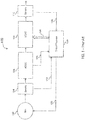
- FIG. 1 a high level block diagram of a VSCF (variable speed constant drive) system 100 having a wound rotor synchronous generator is provided.
- the system includes a 3-stage wound rotor synchronous generator 102 (3-stage generator) comprising a PMG, an exciter generator and a main synchronous output generator.
- the PMG, exciter generator, and main synchronous output generator are not shown in FIG. 1 .
- the control processor 130 controls the voltage produced by the 3-stage generator 102 by supplying an exciter drive current signal 120 to the exciter generator of the 3-stage generator 102.
- the control processor 130 is able to detect the DC signal 124 at the output of the AC/DC conversion stage 106.
- the control processor 130 is able to adaptively modify the exciter driver current 120 based on the detected DC signal 124.
- the control processor 130 requires power for operation.
- the PMG stage of the 3-stage generator 102 supplies power to the control processor enabling the control processor to function.
- the voltage that is output from the 3-stage generator 102 is provided to sensors 104 and is further provided to an AC/DC conversion stage 106 for converting the received AC signal to a DC signal.
- the AC/DC conversion stage 106 receives a 3-phase input from the generator and converts the input into a single DC output.
- the control processor 130 is capable of detecting the voltage at the output of the AC/DC conversion stage 106.
- the control processor 130 is tasked with maintaining a constant voltage at the output of the AC/DC conversion stage 106 which is accomplished by modifying the exciter drive current 120 provided to the 3-stage generator 102.
- the AC/DC conversion stage 106 removes the frequency component of the voltage of the signal received from the 3-stage generator 102.
- the output of the AC/DC conversion stage 106 is coupled to a DC/AC conversion stage 108 where the frequency of the output is controlled by the control processor 130.
- the control processor 130 can be configured to provide a PWM signal 126 to the DC/AC conversion stage 108 to affect the frequency the output.
- the power that is output from the DC/AC conversion stage 108 is coupled to sensor 110 that detects the voltage and current of the output signal. Sensors 110 can provide a feedback signal 128 to the control processor 130.
- the control processor 130 is able to dynamically modify the control signal 126 based on the feedback signal 128.
- FIG. 2 a block diagram of a prior art VSCF (variable speed constant drive) system 200 having a wound rotor synchronous generator is provided.
- the generator 102 receives an exciter drive current signal 120 from control processor 130.
- the control processor 130 is configured to control the DC signal at the output of the AC/DC conversion stage 106 by adapting the exciter drive signal 120 supplied to the generator 102 based on the signal detected voltage signal at 124.
- the signal that is output of the generator 102 is a 3-phase AC signal that is coupled to sensors 104 and is further supplied to the AC/DC conversion stage 106.
- the AC/DC conversion stage 106 converts the 3-phase signal into a single DC output.
- the AC/DC conversion stage 106 is coupled to a DC link capacitor 216 and further coupled to a DC/AC conversion stage 108 where the input DC signal is converted to a 3-phase output signal.
- the voltage and frequency of the output signal 114 is controlled by a control signal 126 provided by the control processor 130.
- the control signal 126 can be a PWM signal.
- the signal that is output of the DC/AC conversion stage 108 passes through filter 218 and sensors 110. Sensors 110 allow the control processor 130 to detect the current, voltage and frequency of the output signal through a feedback signal 128.
- the control processor 130 is configured to dynamically modify the control signal 126 based on the feedback signal 128. After the signal passes through filters 110, the signal is supplied to the line connections 212.
- the output of the DC/AC 108 is supplied to an electromagnetic interference (EMI) and power quality (PQ) filter 218 and to a point of regulation (POR) voltage and output current sensors 110.
- the control processor 130 is configured to read the POR voltage and output current sensors 110 that provide feedback indicating any voltage loss across the filters 218.
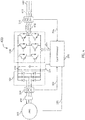
- a PMG based VSCF system 300 in accordance with one or more embodiments is provided.
- the PMG 302 is coupled to a variable input.
- the PMG 302 can be coupled to an aircraft's engine where the input to the PMG 302 varies according to the engine.
- the input can vary from idle while the aircraft is grounded to full power when the aircraft is operating at top speeds.
- the output of the PMG 302 is coupled to sensors 304 and is further coupled to the AC/DC conversion stage 306.
- the AC/DC conversion stage 306 converts the received input into a DC signal.
- a 3-phase signal supplied by the PMG 302 is converted to a single DC signal that is provided to the AC/DC conversion stage 306.
- the system 300 includes a control processor 330 that receives power from the PMG 302 during operation through connection 320.
- the control processor 330 also detects the output voltage of the AC/DC conversion stage 306 that varies with the source driving the PMG 302. In this configuration, the controller processor 330 is reading the voltage through connection 324. The control processor 330 is not controlling the PMG 302 to control the voltage at the output of the AC/DC conversion stage 306.
- the prior art uses a control processor to modify an exciter current supplied to the generator to control the output of the generator.
- the PMG 302 of FIG. 4 does not include an exciter stage and further does not receive an exciter current signal from the control processor 430 for controlling the output of the PMG 302.
- the PMG 302 is coupled to an aircraft engine that drives the PMG 302. As a result, the output voltage of the PMG 302 is proportional to rate of the engine speed.
- the output of the PMG is supplied to PMG voltage and current sensors 304.
- the PMG voltage and current sensors 304 are coupled to an AC/DC conversion stage 306 to convert the AC signal to a DC signal.
- the input from the PMG is a 3-phase input and is converted to a single DC signal.
- the control processor 330 is further configured to detect the DC voltage 324 at the output of the AC/DC conversion stage 306.
- the AC/DC conversion stage 306 is coupled to a DC/AC conversion stage 308 to convert the DC input into a 3-phase output signal.
- the control processor 330 is tasked with controlling the output frequency and the output voltage of the output signal.
- the control processor 330 is configured to read the PMG voltage and current from sensors 310 through feedback signal 328.
- the control processor 330 is coupled to the DC/AC conversion stage 308 and is further configured to provide a control signal 328 for controlling the output voltage and output frequency of the output signal.
- the control processor 330 supplies a PWM signal to the DC/AC conversion stage 308 to adaptively modify the voltage and frequency of the signal that is output of the DC/AC conversion stage 308 according to feedback signal 328.
- the duty cycle of the PWM controls the voltage of the output signal.
- the frequency of the duty cycle controls the frequency of the output signal.
- the control processor 330 is configured to read the output voltage, output current and frequency from a point of regulation (POR) voltage and output current sensors 310.
- POR point of regulation
- the POR voltage and output current sensors 310 provide a feedback signal 328 to the control processor 330 to allow the control processor to effect the change.
- a PMG 302 is configured to receive a variable speed input to produce power.
- the output of the PMG 302 is proportional to the speed of rotation of the shaft of the engine.
- Many applications require power being supplied at a constant voltage and frequency.
- the PMG 302 also provides power through connection 320 to control processer 330.
- the power produced by the PMG 302 is supplied to an AC/DC conversion stage 306 through sensors 304.
- a fault protection mechanism 450 is used to separate the connection between the PMG 302 and current sensors 304.
- the fault protection mechanism 450 will disconnect the PMG 302 to stop the flow of current to the fault.
- a non-limiting example of a fault protection mechanism can be a fusible link.
- the AC/DC conversion stage 306 converts the 3-phase signal to a DC signal.
- the AC/DC conversion stage 306 is coupled to a DC link capacitor 416 and is further coupled to DC/AC conversion stage 308.
- the AC/DC conversion stage 308 converts the DC input and coverts the signal into a 3-phase signal.
- the control processor 330 controls the frequency and voltage of the output of DC/AC conversion stage 308 through control signal 326.
- the control signal 430 is a PWM signal.
- the purpose of the PWM signal is to control the frequency and the voltage of the output signal 414. After the AC/DC conversion stage the voltage is varying with the input driving the PMG 302. The control processor is used to ensure the voltage and the frequency is constant. A PWM signal is used to control the voltage and the frequency at the DC/AC conversion stage 308.
- the output of the DC/AC conversion stage 308 is coupled to the line connector 412 through filter 418 and sensors 310.
- the control processor 330 is configured to detect the voltage and current from the sensors 310.
- sensors 310 are point of regulation (POR) sensors that ensure the output voltage is constant by providing a feedback signal 328 to the control processor 330 causing for the control processor to dynamically adapt the control signal 326 provided to the DC/AC conversion stage.
- the output power is provided at 115V and 400 Hz.
- FIG. 5 illustrates a flow diagram 500 for implementing a PMG (permanent magnet generator) variable speed constant frequency generating system.
- Block 502 provides receiving, via a control processor, power from a PMG, wherein the PMG is coupled to an AC/DC conversion stage.
- Block 504 includes sensing, via the control processor, a DC signal from the AC/DC conversion stage coupled to a DC/AC conversion stage.
- Block 506 includes transmitting a control signal to the DC/AC conversion stage to control a frequency and voltage of the output signal of the DC/AC conversions stage without varying an electrical signal provided to the PMG.
- Block 508 further provides receiving a feedback signal from an output of the DC/AC conversion stage and block 510 provides modifying the control signal to control the frequency and voltage of the output signal.
- the disclosure describes a technique to simplify the complexity of the 3-stage wound rotor synchronous generator implementation.
- an exciter stage, the smaller PMG, and main wound generator are no longer required reducing the load placed on the wings.
- Using a PMG and control processor provides the benefits described above.
Landscapes
- Engineering & Computer Science (AREA)
- Power Engineering (AREA)
- Control Of Eletrric Generators (AREA)
Applications Claiming Priority (1)
| Application Number | Priority Date | Filing Date | Title |
|---|---|---|---|
| US15/142,447 US20170317630A1 (en) | 2016-04-29 | 2016-04-29 | PMG Based Variable Speed Constant Frequency Generating System |
Publications (2)
| Publication Number | Publication Date |
|---|---|
| EP3240184A1 true EP3240184A1 (fr) | 2017-11-01 |
| EP3240184B1 EP3240184B1 (fr) | 2023-04-12 |
Family
ID=58638756
Family Applications (1)
| Application Number | Title | Priority Date | Filing Date |
|---|---|---|---|
| EP17168388.1A Active EP3240184B1 (fr) | 2016-04-29 | 2017-04-27 | Procédé de mise en oeuvre d'un système de génération à vitesse variable et fréquence constante et processeur associé |
Country Status (2)
| Country | Link |
|---|---|
| US (1) | US20170317630A1 (fr) |
| EP (1) | EP3240184B1 (fr) |
Families Citing this family (1)
| Publication number | Priority date | Publication date | Assignee | Title |
|---|---|---|---|---|
| US11183941B2 (en) | 2018-11-06 | 2021-11-23 | Hamilton Sundstrand Corporation | Method to reduce variable speed constant frequency power converter losses during abnormal overloads |
Citations (4)
| Publication number | Priority date | Publication date | Assignee | Title |
|---|---|---|---|---|
| WO1994001922A1 (fr) * | 1992-07-09 | 1994-01-20 | Sundstrand Corporation | Systeme de production d'energie electrique |
| US20090256419A1 (en) * | 2008-04-11 | 2009-10-15 | Anghel Cristian E | Ac/ac power converter for aircraft |
| EP2448100A2 (fr) * | 2010-10-27 | 2012-05-02 | Rockwell Automation Technologies, Inc. | Convertisseurs de puissance multi-phases et papillon correspondant intégré |
| EP2980977A1 (fr) * | 2014-07-28 | 2016-02-03 | Hamilton Sundstrand Corporation | Convertisseurs de puissance pour démarreur/générateurs d'aéronef |
Family Cites Families (14)
| Publication number | Priority date | Publication date | Assignee | Title |
|---|---|---|---|---|
| US5083039B1 (en) * | 1991-02-01 | 1999-11-16 | Zond Energy Systems Inc | Variable speed wind turbine |
| US5798631A (en) * | 1995-10-02 | 1998-08-25 | The State Of Oregon Acting By And Through The State Board Of Higher Education On Behalf Of Oregon State University | Performance optimization controller and control method for doubly-fed machines |
| AU6638400A (en) * | 1999-08-16 | 2001-03-13 | Coleman Powermate, Inc. | System that supplies electrical power and compressed air |
| US7511385B2 (en) * | 2005-11-11 | 2009-03-31 | Converteam Ltd | Power converters |
| US7768165B2 (en) * | 2006-02-02 | 2010-08-03 | Magnetic Applications, Inc. | Controller for AC generator |
| US8030905B2 (en) * | 2008-07-10 | 2011-10-04 | Honeywell International Inc. | Isolated generator control unit (GCU) |
| CN102318157B (zh) * | 2008-12-12 | 2014-07-23 | 维斯塔斯风力系统集团公司 | 控制方法和装置 |
| US8587160B2 (en) * | 2009-09-04 | 2013-11-19 | Rockwell Automation Technologies, Inc. | Grid fault ride-through for current source converter-based wind energy conversion systems |
| US8860236B2 (en) * | 2009-10-19 | 2014-10-14 | Uwm Research Foundation, Inc. | Wind energy power conversion system reducing gearbox stress and improving power stability |
| US8698335B2 (en) * | 2010-06-21 | 2014-04-15 | Rockwell Automation Technologies, Inc. | Low cost current source converters for power generation application |
| EP2403111B1 (fr) * | 2010-06-29 | 2017-05-17 | Siemens Aktiengesellschaft | Générateur, éolienne, procédé d'assemblage d'un générateur et utilisation d'un générateur dans une éolienne |
| US9837824B2 (en) * | 2012-09-03 | 2017-12-05 | Vestas Wind Systems A/S | Connection system for power generation system with DC output |
| ITRM20130272A1 (it) * | 2013-05-08 | 2014-11-09 | Consiglio Nazionale Ricerche | Metodo e relativo sistema per la conversione di energia meccanica, proveniente da un generatore comandato da una turbina, in energia elettrica. |
| CN104753402B (zh) * | 2013-12-25 | 2017-08-25 | 台达电子工业股份有限公司 | 发电机制动系统及其控制方法 |
-
2016
- 2016-04-29 US US15/142,447 patent/US20170317630A1/en not_active Abandoned
-
2017
- 2017-04-27 EP EP17168388.1A patent/EP3240184B1/fr active Active
Patent Citations (4)
| Publication number | Priority date | Publication date | Assignee | Title |
|---|---|---|---|---|
| WO1994001922A1 (fr) * | 1992-07-09 | 1994-01-20 | Sundstrand Corporation | Systeme de production d'energie electrique |
| US20090256419A1 (en) * | 2008-04-11 | 2009-10-15 | Anghel Cristian E | Ac/ac power converter for aircraft |
| EP2448100A2 (fr) * | 2010-10-27 | 2012-05-02 | Rockwell Automation Technologies, Inc. | Convertisseurs de puissance multi-phases et papillon correspondant intégré |
| EP2980977A1 (fr) * | 2014-07-28 | 2016-02-03 | Hamilton Sundstrand Corporation | Convertisseurs de puissance pour démarreur/générateurs d'aéronef |
Also Published As
| Publication number | Publication date |
|---|---|
| US20170317630A1 (en) | 2017-11-02 |
| EP3240184B1 (fr) | 2023-04-12 |
Similar Documents
| Publication | Publication Date | Title |
|---|---|---|
| EP2432978B1 (fr) | Système de démarrage et de génération d'un moteur d'aéronef, et procédé de régulation | |
| KR101474016B1 (ko) | 전력 변환기 | |
| EP3258587B1 (fr) | Commande de puissance à fréquence constante et à vitesse variable | |
| US9573539B2 (en) | Electric system architecture for more-electric engine accessories | |
| EP2020745B1 (fr) | Système de démarrage de moteur avec machine à aimants permanents régulée | |
| US7619327B2 (en) | Hybrid electromechanical power transfer system | |
| EP1826890A2 (fr) | Générateur de démarrage sans balai avec champ d'excitateur contrôlable indépendamment | |
| EP2001121A2 (fr) | Système de démarrage de moteur doté d'une excitation CA en quadrature | |
| EP2040370B1 (fr) | Générateur de moteur de turbine à gaz doté d'une barre CC principale et d'une barre CA accessoire | |
| EP2538546A2 (fr) | Architecture de système électrique et système de génération d'énergie électrique | |
| EP2940272A1 (fr) | Système de carburant de moteur de turbine à gaz | |
| EP2346160B1 (fr) | Amortissement de charge d'entraînement de moteur | |
| CN104024038A (zh) | 用于触发电机的方法和装置 | |
| EP3109997B1 (fr) | Générateur de puissance de fréquence constante à vitesse variable comprenant un excitateur d'aimant permanent | |
| EP2808996A1 (fr) | Liaison à courant continu commandé en tension d'excitation de générateur de fréquence variable | |
| US9166510B1 (en) | Systems utilizing a controllable voltage AC generator system | |
| EP3376663A1 (fr) | Agencements de générateurs et procédés de commande d'agencements de générateurs | |
| EP2045910B1 (fr) | Système démarreur/générateur avec contrôle pour le traitement d'une augmentation de la tension | |
| EP3240184B1 (fr) | Procédé de mise en oeuvre d'un système de génération à vitesse variable et fréquence constante et processeur associé | |
| EP2071692A1 (fr) | Architecture de commande de moteur pour un bus CA haute fréquence | |
| US12334785B2 (en) | Architecture for an electric power generator for aviation | |
| EP3706307B1 (fr) | Architectures hybrides en série utilisant des machines à double alimentation composées | |
| WO1997000201A1 (fr) | Systeme thermique de degivrage d'un element rotatif | |
| RU2573576C2 (ru) | Устройство электропитания постоянным током автономного транспортного судна | |
| CN116324146A (zh) | 泵致动装置及相关的泵送系统、飞行器和燃料供应方法 |
Legal Events
| Date | Code | Title | Description |
|---|---|---|---|
| PUAI | Public reference made under article 153(3) epc to a published international application that has entered the european phase |
Free format text: ORIGINAL CODE: 0009012 |
|
| STAA | Information on the status of an ep patent application or granted ep patent |
Free format text: STATUS: THE APPLICATION HAS BEEN PUBLISHED |
|
| AK | Designated contracting states |
Kind code of ref document: A1 Designated state(s): AL AT BE BG CH CY CZ DE DK EE ES FI FR GB GR HR HU IE IS IT LI LT LU LV MC MK MT NL NO PL PT RO RS SE SI SK SM TR |
|
| AX | Request for extension of the european patent |
Extension state: BA ME |
|
| STAA | Information on the status of an ep patent application or granted ep patent |
Free format text: STATUS: REQUEST FOR EXAMINATION WAS MADE |
|
| 17P | Request for examination filed |
Effective date: 20180501 |
|
| RBV | Designated contracting states (corrected) |
Designated state(s): AL AT BE BG CH CY CZ DE DK EE ES FI FR GB GR HR HU IE IS IT LI LT LU LV MC MK MT NL NO PL PT RO RS SE SI SK SM TR |
|
| STAA | Information on the status of an ep patent application or granted ep patent |
Free format text: STATUS: EXAMINATION IS IN PROGRESS |
|
| 17Q | First examination report despatched |
Effective date: 20200417 |
|
| GRAP | Despatch of communication of intention to grant a patent |
Free format text: ORIGINAL CODE: EPIDOSNIGR1 |
|
| STAA | Information on the status of an ep patent application or granted ep patent |
Free format text: STATUS: GRANT OF PATENT IS INTENDED |
|
| INTG | Intention to grant announced |
Effective date: 20221123 |
|
| GRAS | Grant fee paid |
Free format text: ORIGINAL CODE: EPIDOSNIGR3 |
|
| GRAA | (expected) grant |
Free format text: ORIGINAL CODE: 0009210 |
|
| STAA | Information on the status of an ep patent application or granted ep patent |
Free format text: STATUS: THE PATENT HAS BEEN GRANTED |
|
| AK | Designated contracting states |
Kind code of ref document: B1 Designated state(s): AL AT BE BG CH CY CZ DE DK EE ES FI FR GB GR HR HU IE IS IT LI LT LU LV MC MK MT NL NO PL PT RO RS SE SI SK SM TR |
|
| REG | Reference to a national code |
Ref country code: GB Ref legal event code: FG4D |
|
| REG | Reference to a national code |
Ref country code: CH Ref legal event code: EP |
|
| REG | Reference to a national code |
Ref country code: DE Ref legal event code: R096 Ref document number: 602017067624 Country of ref document: DE |
|
| REG | Reference to a national code |
Ref country code: IE Ref legal event code: FG4D |
|
| REG | Reference to a national code |
Ref country code: AT Ref legal event code: REF Ref document number: 1560344 Country of ref document: AT Kind code of ref document: T Effective date: 20230515 |
|
| P01 | Opt-out of the competence of the unified patent court (upc) registered |
Effective date: 20230522 |
|
| REG | Reference to a national code |
Ref country code: LT Ref legal event code: MG9D |
|
| REG | Reference to a national code |
Ref country code: NL Ref legal event code: MP Effective date: 20230412 |
|
| REG | Reference to a national code |
Ref country code: AT Ref legal event code: MK05 Ref document number: 1560344 Country of ref document: AT Kind code of ref document: T Effective date: 20230412 |
|
| PG25 | Lapsed in a contracting state [announced via postgrant information from national office to epo] |
Ref country code: NL Free format text: LAPSE BECAUSE OF FAILURE TO SUBMIT A TRANSLATION OF THE DESCRIPTION OR TO PAY THE FEE WITHIN THE PRESCRIBED TIME-LIMIT Effective date: 20230412 |
|
| PG25 | Lapsed in a contracting state [announced via postgrant information from national office to epo] |
Ref country code: SE Free format text: LAPSE BECAUSE OF FAILURE TO SUBMIT A TRANSLATION OF THE DESCRIPTION OR TO PAY THE FEE WITHIN THE PRESCRIBED TIME-LIMIT Effective date: 20230412 Ref country code: PT Free format text: LAPSE BECAUSE OF FAILURE TO SUBMIT A TRANSLATION OF THE DESCRIPTION OR TO PAY THE FEE WITHIN THE PRESCRIBED TIME-LIMIT Effective date: 20230814 Ref country code: NO Free format text: LAPSE BECAUSE OF FAILURE TO SUBMIT A TRANSLATION OF THE DESCRIPTION OR TO PAY THE FEE WITHIN THE PRESCRIBED TIME-LIMIT Effective date: 20230712 Ref country code: ES Free format text: LAPSE BECAUSE OF FAILURE TO SUBMIT A TRANSLATION OF THE DESCRIPTION OR TO PAY THE FEE WITHIN THE PRESCRIBED TIME-LIMIT Effective date: 20230412 Ref country code: AT Free format text: LAPSE BECAUSE OF FAILURE TO SUBMIT A TRANSLATION OF THE DESCRIPTION OR TO PAY THE FEE WITHIN THE PRESCRIBED TIME-LIMIT Effective date: 20230412 |
|
| PG25 | Lapsed in a contracting state [announced via postgrant information from national office to epo] |
Ref country code: RS Free format text: LAPSE BECAUSE OF FAILURE TO SUBMIT A TRANSLATION OF THE DESCRIPTION OR TO PAY THE FEE WITHIN THE PRESCRIBED TIME-LIMIT Effective date: 20230412 Ref country code: PL Free format text: LAPSE BECAUSE OF FAILURE TO SUBMIT A TRANSLATION OF THE DESCRIPTION OR TO PAY THE FEE WITHIN THE PRESCRIBED TIME-LIMIT Effective date: 20230412 Ref country code: LV Free format text: LAPSE BECAUSE OF FAILURE TO SUBMIT A TRANSLATION OF THE DESCRIPTION OR TO PAY THE FEE WITHIN THE PRESCRIBED TIME-LIMIT Effective date: 20230412 Ref country code: LT Free format text: LAPSE BECAUSE OF FAILURE TO SUBMIT A TRANSLATION OF THE DESCRIPTION OR TO PAY THE FEE WITHIN THE PRESCRIBED TIME-LIMIT Effective date: 20230412 Ref country code: IS Free format text: LAPSE BECAUSE OF FAILURE TO SUBMIT A TRANSLATION OF THE DESCRIPTION OR TO PAY THE FEE WITHIN THE PRESCRIBED TIME-LIMIT Effective date: 20230812 Ref country code: HR Free format text: LAPSE BECAUSE OF FAILURE TO SUBMIT A TRANSLATION OF THE DESCRIPTION OR TO PAY THE FEE WITHIN THE PRESCRIBED TIME-LIMIT Effective date: 20230412 Ref country code: GR Free format text: LAPSE BECAUSE OF FAILURE TO SUBMIT A TRANSLATION OF THE DESCRIPTION OR TO PAY THE FEE WITHIN THE PRESCRIBED TIME-LIMIT Effective date: 20230713 Ref country code: AL Free format text: LAPSE BECAUSE OF FAILURE TO SUBMIT A TRANSLATION OF THE DESCRIPTION OR TO PAY THE FEE WITHIN THE PRESCRIBED TIME-LIMIT Effective date: 20230412 |
|
| REG | Reference to a national code |
Ref country code: CH Ref legal event code: PL |
|
| PG25 | Lapsed in a contracting state [announced via postgrant information from national office to epo] |
Ref country code: LU Free format text: LAPSE BECAUSE OF NON-PAYMENT OF DUE FEES Effective date: 20230427 Ref country code: FI Free format text: LAPSE BECAUSE OF FAILURE TO SUBMIT A TRANSLATION OF THE DESCRIPTION OR TO PAY THE FEE WITHIN THE PRESCRIBED TIME-LIMIT Effective date: 20230412 |
|
| REG | Reference to a national code |
Ref country code: BE Ref legal event code: MM Effective date: 20230430 |
|
| REG | Reference to a national code |
Ref country code: DE Ref legal event code: R097 Ref document number: 602017067624 Country of ref document: DE |
|
| PG25 | Lapsed in a contracting state [announced via postgrant information from national office to epo] |
Ref country code: SK Free format text: LAPSE BECAUSE OF FAILURE TO SUBMIT A TRANSLATION OF THE DESCRIPTION OR TO PAY THE FEE WITHIN THE PRESCRIBED TIME-LIMIT Effective date: 20230412 |
|
| PG25 | Lapsed in a contracting state [announced via postgrant information from national office to epo] |
Ref country code: MC Free format text: LAPSE BECAUSE OF FAILURE TO SUBMIT A TRANSLATION OF THE DESCRIPTION OR TO PAY THE FEE WITHIN THE PRESCRIBED TIME-LIMIT Effective date: 20230412 |
|
| PG25 | Lapsed in a contracting state [announced via postgrant information from national office to epo] |
Ref country code: SM Free format text: LAPSE BECAUSE OF FAILURE TO SUBMIT A TRANSLATION OF THE DESCRIPTION OR TO PAY THE FEE WITHIN THE PRESCRIBED TIME-LIMIT Effective date: 20230412 Ref country code: SK Free format text: LAPSE BECAUSE OF FAILURE TO SUBMIT A TRANSLATION OF THE DESCRIPTION OR TO PAY THE FEE WITHIN THE PRESCRIBED TIME-LIMIT Effective date: 20230412 Ref country code: RO Free format text: LAPSE BECAUSE OF FAILURE TO SUBMIT A TRANSLATION OF THE DESCRIPTION OR TO PAY THE FEE WITHIN THE PRESCRIBED TIME-LIMIT Effective date: 20230412 Ref country code: MC Free format text: LAPSE BECAUSE OF FAILURE TO SUBMIT A TRANSLATION OF THE DESCRIPTION OR TO PAY THE FEE WITHIN THE PRESCRIBED TIME-LIMIT Effective date: 20230412 Ref country code: LI Free format text: LAPSE BECAUSE OF NON-PAYMENT OF DUE FEES Effective date: 20230430 Ref country code: EE Free format text: LAPSE BECAUSE OF FAILURE TO SUBMIT A TRANSLATION OF THE DESCRIPTION OR TO PAY THE FEE WITHIN THE PRESCRIBED TIME-LIMIT Effective date: 20230412 Ref country code: DK Free format text: LAPSE BECAUSE OF FAILURE TO SUBMIT A TRANSLATION OF THE DESCRIPTION OR TO PAY THE FEE WITHIN THE PRESCRIBED TIME-LIMIT Effective date: 20230412 Ref country code: CZ Free format text: LAPSE BECAUSE OF FAILURE TO SUBMIT A TRANSLATION OF THE DESCRIPTION OR TO PAY THE FEE WITHIN THE PRESCRIBED TIME-LIMIT Effective date: 20230412 Ref country code: CH Free format text: LAPSE BECAUSE OF NON-PAYMENT OF DUE FEES Effective date: 20230430 |
|
| REG | Reference to a national code |
Ref country code: IE Ref legal event code: MM4A |
|
| PLBE | No opposition filed within time limit |
Free format text: ORIGINAL CODE: 0009261 |
|
| STAA | Information on the status of an ep patent application or granted ep patent |
Free format text: STATUS: NO OPPOSITION FILED WITHIN TIME LIMIT |
|
| PG25 | Lapsed in a contracting state [announced via postgrant information from national office to epo] |
Ref country code: BE Free format text: LAPSE BECAUSE OF NON-PAYMENT OF DUE FEES Effective date: 20230430 |
|
| 26N | No opposition filed |
Effective date: 20240115 |
|
| PG25 | Lapsed in a contracting state [announced via postgrant information from national office to epo] |
Ref country code: IE Free format text: LAPSE BECAUSE OF NON-PAYMENT OF DUE FEES Effective date: 20230427 |
|
| PG25 | Lapsed in a contracting state [announced via postgrant information from national office to epo] |
Ref country code: IE Free format text: LAPSE BECAUSE OF NON-PAYMENT OF DUE FEES Effective date: 20230427 |
|
| PG25 | Lapsed in a contracting state [announced via postgrant information from national office to epo] |
Ref country code: SI Free format text: LAPSE BECAUSE OF FAILURE TO SUBMIT A TRANSLATION OF THE DESCRIPTION OR TO PAY THE FEE WITHIN THE PRESCRIBED TIME-LIMIT Effective date: 20230412 |
|
| PG25 | Lapsed in a contracting state [announced via postgrant information from national office to epo] |
Ref country code: SI Free format text: LAPSE BECAUSE OF FAILURE TO SUBMIT A TRANSLATION OF THE DESCRIPTION OR TO PAY THE FEE WITHIN THE PRESCRIBED TIME-LIMIT Effective date: 20230412 Ref country code: IT Free format text: LAPSE BECAUSE OF FAILURE TO SUBMIT A TRANSLATION OF THE DESCRIPTION OR TO PAY THE FEE WITHIN THE PRESCRIBED TIME-LIMIT Effective date: 20230412 |
|
| PG25 | Lapsed in a contracting state [announced via postgrant information from national office to epo] |
Ref country code: BG Free format text: LAPSE BECAUSE OF FAILURE TO SUBMIT A TRANSLATION OF THE DESCRIPTION OR TO PAY THE FEE WITHIN THE PRESCRIBED TIME-LIMIT Effective date: 20230412 |
|
| PG25 | Lapsed in a contracting state [announced via postgrant information from national office to epo] |
Ref country code: BG Free format text: LAPSE BECAUSE OF FAILURE TO SUBMIT A TRANSLATION OF THE DESCRIPTION OR TO PAY THE FEE WITHIN THE PRESCRIBED TIME-LIMIT Effective date: 20230412 |
|
| PGFP | Annual fee paid to national office [announced via postgrant information from national office to epo] |
Ref country code: DE Payment date: 20250319 Year of fee payment: 9 |
|
| PG25 | Lapsed in a contracting state [announced via postgrant information from national office to epo] |
Ref country code: CY Free format text: LAPSE BECAUSE OF FAILURE TO SUBMIT A TRANSLATION OF THE DESCRIPTION OR TO PAY THE FEE WITHIN THE PRESCRIBED TIME-LIMIT; INVALID AB INITIO Effective date: 20170427 |
|
| PG25 | Lapsed in a contracting state [announced via postgrant information from national office to epo] |
Ref country code: HU Free format text: LAPSE BECAUSE OF FAILURE TO SUBMIT A TRANSLATION OF THE DESCRIPTION OR TO PAY THE FEE WITHIN THE PRESCRIBED TIME-LIMIT; INVALID AB INITIO Effective date: 20170427 |
|
| PG25 | Lapsed in a contracting state [announced via postgrant information from national office to epo] |
Ref country code: TR Free format text: LAPSE BECAUSE OF FAILURE TO SUBMIT A TRANSLATION OF THE DESCRIPTION OR TO PAY THE FEE WITHIN THE PRESCRIBED TIME-LIMIT Effective date: 20230412 |
|
| PGFP | Annual fee paid to national office [announced via postgrant information from national office to epo] |
Ref country code: GB Payment date: 20260319 Year of fee payment: 10 |
|
| PGFP | Annual fee paid to national office [announced via postgrant information from national office to epo] |
Ref country code: FR Payment date: 20260320 Year of fee payment: 10 |