EP3240325B1 - Appareil de mesure, et procédé de mesure - Google Patents
Appareil de mesure, et procédé de mesure Download PDFInfo
- Publication number
- EP3240325B1 EP3240325B1 EP15871932.8A EP15871932A EP3240325B1 EP 3240325 B1 EP3240325 B1 EP 3240325B1 EP 15871932 A EP15871932 A EP 15871932A EP 3240325 B1 EP3240325 B1 EP 3240325B1
- Authority
- EP
- European Patent Office
- Prior art keywords
- measurement
- measurement result
- user equipment
- reference signal
- high interference
- Prior art date
- Legal status (The legal status is an assumption and is not a legal conclusion. Google has not performed a legal analysis and makes no representation as to the accuracy of the status listed.)
- Active
Links
Images






Classifications
-
- H—ELECTRICITY
- H04—ELECTRIC COMMUNICATION TECHNIQUE
- H04W—WIRELESS COMMUNICATION NETWORKS
- H04W24/00—Supervisory, monitoring or testing arrangements
- H04W24/08—Testing, supervising or monitoring using real traffic
-
- H—ELECTRICITY
- H04—ELECTRIC COMMUNICATION TECHNIQUE
- H04W—WIRELESS COMMUNICATION NETWORKS
- H04W36/00—Hand-off or reselection arrangements
- H04W36/34—Reselection control
- H04W36/38—Reselection control by fixed network equipment
- H04W36/385—Reselection control by fixed network equipment of the core network
-
- H—ELECTRICITY
- H04—ELECTRIC COMMUNICATION TECHNIQUE
- H04B—TRANSMISSION
- H04B17/00—Monitoring; Testing
- H04B17/30—Monitoring; Testing of propagation channels
- H04B17/309—Measuring or estimating channel quality parameters
- H04B17/336—Signal-to-interference ratio [SIR] or carrier-to-interference ratio [CIR]
-
- H—ELECTRICITY
- H04—ELECTRIC COMMUNICATION TECHNIQUE
- H04W—WIRELESS COMMUNICATION NETWORKS
- H04W16/00—Network planning, e.g. coverage or traffic planning tools; Network deployment, e.g. resource partitioning or cells structures
- H04W16/14—Spectrum sharing arrangements between different networks
-
- H—ELECTRICITY
- H04—ELECTRIC COMMUNICATION TECHNIQUE
- H04W—WIRELESS COMMUNICATION NETWORKS
- H04W24/00—Supervisory, monitoring or testing arrangements
- H04W24/10—Scheduling measurement reports ; Arrangements for measurement reports
-
- H—ELECTRICITY
- H04—ELECTRIC COMMUNICATION TECHNIQUE
- H04W—WIRELESS COMMUNICATION NETWORKS
- H04W36/00—Hand-off or reselection arrangements
- H04W36/04—Reselecting a cell layer in multi-layered cells
-
- H—ELECTRICITY
- H04—ELECTRIC COMMUNICATION TECHNIQUE
- H04W—WIRELESS COMMUNICATION NETWORKS
- H04W36/00—Hand-off or reselection arrangements
- H04W36/16—Performing reselection for specific purposes
- H04W36/20—Performing reselection for specific purposes for optimising the interference level
-
- H—ELECTRICITY
- H04—ELECTRIC COMMUNICATION TECHNIQUE
- H04W—WIRELESS COMMUNICATION NETWORKS
- H04W36/00—Hand-off or reselection arrangements
- H04W36/24—Reselection being triggered by specific parameters
- H04W36/30—Reselection being triggered by specific parameters by measured or perceived connection quality data
- H04W36/304—Reselection being triggered by specific parameters by measured or perceived connection quality data due to measured or perceived resources with higher communication quality
-
- H—ELECTRICITY
- H04—ELECTRIC COMMUNICATION TECHNIQUE
- H04W—WIRELESS COMMUNICATION NETWORKS
- H04W84/00—Network topologies
- H04W84/02—Hierarchically pre-organised networks, e.g. paging networks, cellular networks, WLAN [Wireless Local Area Network] or WLL [Wireless Local Loop]
- H04W84/04—Large scale networks; Deep hierarchical networks
- H04W84/042—Public Land Mobile systems, e.g. cellular systems
- H04W84/045—Public Land Mobile systems, e.g. cellular systems using private Base Stations, e.g. femto Base Stations, home Node B
Definitions
- the present disclosure relates to the field of wireless communication technology, and particularly relates to a User Equipment, UE, for performing radio resource management measurement on a reference signal in a small cell scene.
- UE User Equipment
- a small cell network is considered as an effective means to deal with rapid increasing of data traffic. Due to dense deployment of small cells, synchronization signals and reference signals will be interfered severely among cells. Therefore, it needs to solve the problem of performing radio resource management (RRM) measurement on the reference signal in the small cell scene.
- RRM radio resource management
- an operator may deploy more small cells so as to utilize all available spectrum resources as much as possible.
- Some unlicensed frequency bands for example a 5GHz frequency band have rich spectrum resources, and effective utilizing of these frequency bands may assist the operator to provide faster and better services.
- LTE-U long term evolution-unlicensed
- LAA Licensed-Assisted Access
- the RANI design a new reference signal, i.e., a discovery reference signal (DRS), to support an ON/OFF process of the small cell.
- DRS discovery reference signal
- the DRS-based measurement facilitates the subsequent ON/OFF of the cell and user switch. Due to new characteristics of the DRS, the RRM measurement based on the DRS is necessarily different from the RRM measurement based on other reference signals. Therefore, the RRM measurement based on the DRS needs to be corrected and improved accordingly.
- Prior art includes: US 2014/334320 A1 , US 2012/207044A1 , WO 2014/116049A1 and ETRI "Discussion on small-cell discovery", 3GPP Draft, R1-131141, SCE-Discovery, 6 April 2013 ; and US 2012/214540 A1 .
- an object of the present disclosure is to provide a User Equipment, UE, which can perform RRM measurement on a reference signal in a small cell scene, so as to perform mobility management on user equipment.
- the embodiments of the present disclosure for the problems such as high interference in the small cell scene, characteristics of the reference signal itself and the like, reliable and accurate radio resource management measurement for the reference signal are realized, and it also enables the user equipment to perform the RRM measurement with low power consumption.
- Figure 1 is a block diagram illustrating a function configuration example of a management device on a user equipment side in a wireless communication system according to an embodiment of the present disclosure.
- a management device 100 includes a measuring unit 102, an interference judging unit 104, a filtering unit 106 and a mobility managing unit 108. Subsequently, function configuration examples of respective units are described in detail.
- the measuring unit 102 is configured to perform radio resource management measurement on a reference signal of a target cell.
- the target cell is a small cell supporting operating in a long term evolution-unlicensed frequency band.
- the small cell operates in a 5GHz frequency band (a Wi-Fi frequency band) using the Licensed-Assisted Access (LAA) technology.
- LAA Licensed-Assisted Access
- the reference signal here is a signal including a pilot sequence, and may include for example at least one of a discovery reference signal (DRS), a cell specific reference signal (CRS) and a channel state indicator-reference signal (CSI-RS).
- DRS discovery reference signal
- CRS cell specific reference signal
- CSI-RS channel state indicator-reference signal
- the discovery reference signal is a new reference signal proposed by RANI for the small cell scene.
- the DRS is proposed to assist load balancing, interference coordination, RRM measurement and cell identification among dense small cells.
- the DRS may include CRS and synchronization signals (a primary synchronization signal (PSS) and a secondary synchronization signal (SSS)), and may further include CSI-RS in some cases.
- PSS primary synchronization signal
- SSS secondary synchronization signal
- CSI-RS CSI-RS in some cases.
- the DRS has new features. Therefore, it needs to modify the conventional measurement manner to realize the RRM measurement for the reference signal in the small cell scene.
- the measuring unit 102 may be further configured to measure the reference signal by aligning a measuring time instant at which the reference signal is measured with a sending time instant at which the target cell sends the reference signal.
- the measuring unit 102 may measure the reference signal in a relaxed measurement manner.
- the conventional reference signal such as the CRS appears in each sub-frame, and is an "always-on" signal.
- a cycle of the DRS is much longer (which may be 40/80/160 ms).
- due to the interference coordination there may be offsets between the DRSs of different small cells.
- the burst gap appears every other T burst .
- a duration of each measurement gap is T gap
- an interval between the measurement gaps is MGRP.
- a base station still performs a measurement configuration for the user equipment in the conventional manner, for example including dense measurement gaps, but the user equipment may perform continuous but less frequent inter-frequency small cell measurement based on a subset of the measurement gaps configured by the base station, so as to detect small cells.
- the present disclosure designs a manner of performing RRM measurement on the DRS to efficiently realize the relaxed measurement, in which the measuring unit 102 may measure the reference signal by aligning a duration (T gap ) of each of the measuring gaps in the burst gap (T burst ) of the relaxed measurement manner with the sending time instant at which the target cell sends the reference signal, configuring the interval (MGRP) among the measuring gaps of the relaxed measurement manner as integral multiples of the measuring cycle (40/80/160ms) for the reference signal, and configuring the burst gap of the relaxed measurement manner as integral multiples of the interval among the measuring gaps.
- T gap duration of each of the measuring gaps in the burst gap (T burst ) of the relaxed measurement manner with the sending time instant at which the target cell sends the reference signal
- the interval (MGRP) among the measuring gaps of the relaxed measurement manner as integral multiples of the measuring cycle (40/80/160ms) for the reference signal
- the burst gap of the relaxed measurement manner as integral multiples of the interval among the measuring
- the measuring unit 102 measures the reference signal in the relaxed measurement manner by aligning the measuring time instant with the sending time instant for the reference signal, thereby reducing energy consumption of the user equipment and obtaining a relatively accurate and reliable measurement result.
- the interference judging unit 104 may be configured to judge whether interference in the measurement result of the measuring unit 102 satisfies a predetermined condition, and label a measurement result the interference of which satisfies the predetermined condition as a measurement result with high interference.
- the measurement unit 102 may preferably measure the reference signal in the long term evolution-unlicensed frequency band.
- the small cell operates in the unlicensed frequency band, thus the small cell is susceptible to interference from other apparatuses, thereby resulting in further pollution for the DRS and making the user equipment can not obtain an accurate measurement result.
- RSRQ (N ⁇ RSRP)/DRSSI.
- the DRSSI is measured on OFDM symbols of a downlink part of all measurement sub-frames and indicates a reception signal strength indication measured based on the DRS; the RSRP is measured on OFDM symbols of sub-frames in which the DRS signal appears and indicates a reference signal reception power measured based on the DRS; and N indicates the number of resource blocks of a measurement bandwidth of the DRSSI.
- the measurement result can be determined as a measurement result with high interference.
- the method for calculating the interference part described here is only exemplary, and those skilled in the art can obtain the interference part in the measurement result in other ways, which will not be limited in the present disclosure.
- the filtering unit 106 may be configured to perform for example a Layer-3 (L3) filtering in the 3GPP LTE-A standard on the measurement result.
- L3 Layer-3
- the measuring unit 102 of the user equipment firstly performs intra-frequency/inter-frequency measurement on Layer 1 (LI) in a fixed measurement cycle, then the L1 reports a measurement result to the L3 at a certain interval, and then the L3 filters the current measurement result and measurement results stored previously.
- LI Layer 1
- the L3 filtering may be performed to generate a stable measurement result.
- the mobility managing unit 108 may be configured to perform mobility management on the user equipment based on the measurement result with high interference.
- Figure 3 shows a function configuration example of a mobility managing unit in the management device according to an embodiment of the present disclosure.
- a mobility managing unit 108 may include at least one of a cell reselecting unit 1081 and a reporting unit 1082.
- the cell reselecting unit 1081 may be configured for cell reselection in a case that the user equipment is in an idle state
- the reporting unit 1082 may be configured for reporting a measurement result in a case that the user equipment is in a connected state.
- actions related to the measurement includes adding/deleting, activating/deactivating of component carriers and cell handover in a case that the user equipment is in the connected state (RRC_connected), and the cell reselection in a case that the user equipment is in the idle state (RRC_idle).
- RRC_connected the connected state
- RRC_idle the cell reselection in a case that the user equipment is in the idle state
- the user equipment needs to report the measurement result to a base station, so that the base station instructs the user equipment to perform handover to a corresponding cell based on the measurement result.
- the user equipment does not need to report the measurement result to the base station, but selects a corresponding cell according to the measurement result.
- one component carrier generally corresponds to one cell, for example a cell performing carrier aggregation with other component carriers.
- the cell may be a macro cell or a small cell. Therefore, in some cases, when a certain component carrier is referred, it may be understood as a certain cell corresponding to the certain component carrier.
- Figure 4 is a block diagram illustrating a function configuration example of a reporting unit in the management device according to an embodiment of the present disclosure.
- a reporting unit 1082 may include a measurement report generating unit 1082-1.
- the measurement report generating unit 1082-1 may be configured to generate a measurement report to contain statistical information on the measurement result with high interference.
- the statistical information on the measurement result with high interference may include but not limited to at least one of: a total number of the measurement results with high interference appearing in a predetermined time period, a number of the measurement results with high interference appearing continuously, and statistical results related to the values of the measuring results with high interference (for example an average value of the measurement results with high interference, an offset of the average value relative to a reference value, and the like).
- the user equipment reports the measurement result to the base station in any case and also reports the statistical information on the measurement result with high interference to the base station, such that the base station determines, according to the received measurement report, a radio resource management scheme, for example mobility management such as adding, deleting, activating and deactivating of component carriers and cell handover, or a resource scheduling scheme such as power control, channel allocation and load control.
- a radio resource management scheme for example mobility management such as adding, deleting, activating and deactivating of component carriers and cell handover, or a resource scheduling scheme such as power control, channel allocation and load control.
- Figure 5 is a block diagram illustrating another function configuration example of the reporting unit in the management device according to an embodiment of the present disclosure.
- the reporting unit 1082 may include a reporting rule evaluating unit 1082-2, which may be configured to evaluate, based on the measurement result with high interference, whether to report a filtered measurement result of the target cell and/or whether to report the statistical information on the measurement result with high interference.
- the base station in performing a measurement configuration for the user equipment, may contain in configuration signaling information related to a rule for reporting the measurement result. For example, for a certain cell (for example a neighbor cell), if the information related to the measurement result with high interference satisfies a predetermined condition (for example the measurement result with high interference being greater than a predetermined threshold, a predetermined number of measurement results with high interference appearing continuously, the number of the measurement results with high reference appearing within a predetermined time period being greater than a predetermined threshold, or the like), the user equipment may not report the measurement report related to the cell, or may contain the statistical information on the measurement result with high interference in the measurement report.
- a predetermined condition for example the measurement result with high interference being greater than a predetermined threshold, a predetermined number of measurement results with high interference appearing continuously, the number of the measurement results with high reference appearing within a predetermined time period being greater than a predetermined threshold, or the like.
- the reporting rule evaluating unit 1082-2 may evaluate, based on the measurement configuration from a base station and the received measurement result with high interference, whether to conform to the reporting rule, i.e., whether to report the measurement result of the target cell or whether to report the statistical information on the measurement result with high interference.
- the measurement configuration information generated by the base station may include the reporting rule for the measurement result with high interference, so that the user equipment may evaluate whether to report corresponding information.
- the reporting unit 1082 may selectively contain the filtered measurement result of the target cell and the statistical information on the measurement result with high interference in the measurement report to be reported the base station, according to the evaluation result of the reporting rule evaluating unit 1082-2.
- the user equipment may autonomously determine whether to report the measurement reports of certain cells. For example, for a target cell the measurement result with high interference of which satisfies the predetermined condition (for example a cell which is not suitable to serve as a handover target), measurement result thereof may be not reported, thereby reducing signaling interaction between the user equipment and the base station, saving resources and improving efficiency.
- the predetermined condition for example a cell which is not suitable to serve as a handover target
- the user equipment performs carrier aggregation communication with the base station. Specifically, the user equipment communicates with the base station over a primary component carrier PCC (corresponding to a primary cell Pcell) on a licensed frequency band and a secondary component carrier SCC (corresponding to a secondary cell Scell) on an unlicensed frequency band.
- PCC primary component carrier
- SCC secondary component carrier
- the user equipment performs RRM measurement on the SCC, so as to determine a resource management strategy, for example, whether to deactivate the SCC or replace the SCC with another component carrier.
- the SCC in a case that the RRM measurement result of the SCC after being subject to Layer-3 filtering from the user equipment, for example the RSRP, is less than a predetermined threshold or less than the RSRP of other candidate component carrier, the SCC triggers a corresponding report event, such that the base station determines to deactivate the SCC or replace the SCC with another component carrier based on the measurement report.
- the reference signal carried by the SCC on the unlicensed frequency band may temporarily suffer high interference from a wifi signal for example, but the component carrier on the unlicensed frequency band only functions as SCC in the example, and thus short-time high interference on the SCC will not substantively influence communication of the user equipment.
- the L3 filtering unit continuously outputs a lower measurement result and thus may trigger a predetermined report event, such as an event A2 (quality of a serving cell is lower than a threshold)/A6 (quality of an intra-frequency adjacent cell is higher than quality of a secondary cell) in the LTE-A, thereby wasting signaling resources and even resulting in that the base station improperly or frequently deactivates/replaces the corresponding SCC.
- a predetermined report event such as an event A2 (quality of a serving cell is lower than a threshold)/A6 (quality of an intra-frequency adjacent cell is higher than quality of a secondary cell) in the LTE-A
- the reporting rule evaluating unit 1082-2 may be configured to evaluate, according to the measurement result with high interference, whether to report a filtered measurement result of the target SCC and/or whether to report the statistical information on the measurement result with high interference of the target SCC so as to be judged by the base station. For example, even if the L3 filtering output conforms to the conventional event reporting condition, the reporting rule evaluating unit 1082-2 still needs to evaluate whether the measurement result with high interference on the target SCC (for example the measurement result with high interference included in measurement results input to the L3 filtering) is short-time high interference or continuous high interference for example, thereby further determining whether to report the measurement result.
- the measurement result with high interference on the target SCC for example the measurement result with high interference included in measurement results input to the L3 filtering
- continuous high interference for example
- the reporting rule evaluating unit 1082-2 stops reporting a corresponding event in a case of determining that the interference on the target SCC is short-time high interference according to the statistical information on the measurement result with high interference; and reports a corresponding measurement result in a case of determining that the interference on the target SCC is continuous high interference.
- the measurement result with high interference among the measurement results may be corrected, so as to eliminate influence of the interference on the mobility management .
- the preferred example is described in detail in conjunction with Figure 6 .
- Figure 6 is a block diagram illustrating another function configuration example of the management device on the user equipment device side in a wireless communication system according to an embodiment of the present disclosure.
- a management device 600 may include a measuring unit 602, an interference judging unit 604, an interference correcting unit 606, a filtering unit 608 and a mobility managing unit 610.
- Function configuration examples of the measuring unit 602, the interference judging unit 604, the filtering unit 608 and the mobility managing unit 610 are the same as the function configuration examples of the measuring unit 102, the interference judging unit 104, the filtering unit 106 and the mobility managing unit 108 described above, which are not repeated here.
- the interference correcting unit 606 is described in detail.
- the interference correcting unit 606 may be configured to correct the measurement result with high interference so as to eliminate influence on the mobility management from the interference included in the measurement result, and output the corrected measurement result to the filtering unit 608.
- the interference correcting unit 606 may be configured to respectively correct each measurement result with high interference or collectively correct all measurement results with high interference among a predetermined number of measurement results.
- respectively correcting each measurement result with high interference includes at least one of the following ways: ignoring the measurement result with high interference, thereby not inputting the measurement result with high interference to the filtering unit 608; taking a preceding measurement result without high interference as a current measurement result and inputting it to the filtering unit 608; and subtracting from the measurement result with high interference an increased interference value of the measurement result with high interference relative to a predetermined interference threshold and inputting it to the filtering unit 608.
- each of all the measurement results with high interference may be corrected in one of the above-described ways.
- the user equipment may not correct the measurement results with high interference, but reports the interference condition to the base station to make a decision by the base station.
- labeling and reporting of continuous measurement results with high interference depend on a correcting method for the measurement result with high interference. Specifically, in a case of respectively correcting each measurement result with high interference, the user equipment needs to label each measurement result with high interference. If a predetermined number of measurement results with high interference for example appear continuously or if a predetermined number of measurement results with high interference or more appear within a certain predefined time window, a continuous high interference event will be triggered, and the user equipment reports the event to the base station.
- the user equipment needs to maintain a predefined time window (corresponding to the predetermined number of measurement results described above), and if the predetermined number of measurement results with high interference or more appear within the time window, the continuous high interference event will be triggered, and the user equipment reports the event to the base station.
- influence of the interference may be also reduced by enhancing the L3 filter. This case is described in detail with reference to Figure 7 hereinafter.
- Figure 7 is a block diagram illustrating another function configuration example of the management device on the user equipment side in a wireless communication system according to an embodiment of the present disclosure.
- a management device 700 may include a measuring unit 702, an interference judging unit 704, an adjusting unit 706, a filtering unit 708 and a mobility managing unit 710.
- Function configuration examples of the measuring unit 702, the interference judging unit 704, the filtering unit 708 and the mobility managing unit 710 are the same as function configuration examples of the measuring unit 102, the interference judging unit 104, the filtering unit 106 and the mobility managing unit 108 described above, which are not repeated here.
- a function configuration example of the adjusting unit 706 is described in detail.
- the adjusting unit 706 may be configured to adjust relevant filtering parameters of the filtering unit, so as to reduce influence on the mobility management from the measurement result with high interference.
- the adjusting unit 706 may be further configured to respectively adjust relevant filtering parameters for each measurement result with high interference or collectively adjust relevant filtering parameters for all measurement results with high interference among a predetermined number of measurement results.
- an RRM measurement manner suitable for the scene is proposed, enabling to obtain a reliable and accurate measurement result for the mobility management.
- the activating/deactivating of the component carriers and the cell handover in the mobility management have been described above.
- the interference problem for a scene in which a channel quality changes quickly such as the LTE-U frequency band or the like.
- the interference may be corrected or the filter parameter may be adjusted to eliminate influence of the interference.
- Specific processing ways are substantially the same as those in the embodiments described above, which are not repeated here.
- the cell reselecting unit 1082 may consider lowering a reselection priority of the cell for example.
- Figure 8 is a block diagram illustrating a function configuration example of a measurement device on a user equipment side in a wireless communication system according to an embodiment of the present disclosure.
- a measurement device 800 may include a primary cell discovering unit 802, an interacting unit 804, a sending time instant determining unit 806 and a measuring unit 808. Subsequently, function configuration examples of respective units are described in detail.
- the primary cell discovering unit 802 may be configured to discover a primary cell in a macro cell and obtain a sending time instant at which the primary cell sends a reference signal, where the primary cell is a small cell keeping connection with the user equipment all the time.
- the reference signal here may include at least one of a discovery reference signal (DRS), a cell-specific reference signal (CRS) and a channel state indicator-reference signal (CSI-RS).
- DRS discovery reference signal
- CRS cell-specific reference signal
- CSI-RS channel state indicator-reference signal
- Such small cell may be considered as a special small cell (i.e., the primary cell), for example a pCell defined in a dual link, which may stably provide services for the user equipment. Therefore, the pCell in the present disclosure serves as a reference relative to which sending time instants of reference signals of other small cells are set, and respective small cells have different offsets of the sending time instants of the reference signals relative to the pCell.
- the primary cell discovering unit 802 may be configured to discover the primary cell using a default relaxed measurement configuration for the small cell discovery, for example by performing the relaxed measurement as described with reference to Figure 2 above.
- the primary cell discovering unit 802 may be also configured to discover the primary cell using the conventional measurement manners, and the user equipment discovers other small cells by turning to the relaxed measurement manner after discovering the primary cell (determining the time sequence of the reference signal of the primary cell). Since the user equipment discovers the primary cell with no reference information, discovery efficiency can be improved with the compact conventional measurement manner. After determining the time sequence of the primary cell (a reference for other cells), the user equipment may set the relaxed measurement manners for other small cells, thereby realizing the small cell discovery in an energy saving and efficient manner.
- the interacting unit 804 may be configured to interact with a macro base station corresponding to the macro cell or a base station corresponding to the primary cell so as to obtain a reference signal measurement timing configuration for respective small cells in a predetermined range (for example in a macro cell covering the primary cell) with the time sequence of the primary cell as a reference, where the reference signal measurement timing configuration includes measuring cycles for the reference signals of all small cells in the predetermined range (for example in the macro cell) and offsets between sending time instants at which other small cells send the reference signals and the sending time instants at which the primary cell sends the reference signal.
- all small cells in the macro cell support an ON/OFF mechanism.
- the sending time instant determining unit 806 may be configured to determine the sending time instants at which other small cells send the reference signal according to the sending time instant at which the primary cell sends the reference signal and the determined offsets.
- the measuring unit 808 may be configured to measure, for each small cell, the reference signal of the small cell by aligning a measuring time instant at which the reference signal of the small cell is measured with a sending time instant at which the small cell sends the reference signal.
- the measuring unit 808 may be configured to measure the reference signal in a relaxed measurement manner.
- the measuring unit 808 may measure the reference signal by aligning a duration of each of measuring gaps in a burst gap of the relaxed measurement manner with the sending time instant, configuring an interval among the measuring gaps of the relaxed measurement manner as integral multiples of a measuring cycle for the reference signal, and configuring the burst gap of the relaxed measurement manner as integral multiples of the interval among the measuring gaps.
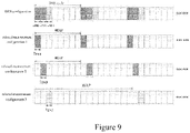
- Figure 9 shows an example of a reference signal measuring timing configuration based on a relaxed measurement manner according to an embodiment of the present disclosure.
- the duration T gap of each of measuring gaps in the burst gap of the relaxed measurement manner is aligned with a time instant at which a corresponding measured cell sends a DRS; and regarding the cycle, the interval MGRP among the measuring gaps of the relaxed measurement manner is configured to be the same as a DRS cycle (40/80/160 ms) of the corresponding measured cell (for example eNB1 and eNB2 in Figure 9 ) or be integral multiples of the DRS cycle of the corresponding measured cell (for example eNB3 in Figure 9 ).
- the burst gap T burst of the relaxed measurement manner is configured as integral multiples of the MGRP, to ensure the DRS of a corresponding cell can be measured in each burst gap of the relaxed measurement manner.
- the DRS is not the "always on" reference signal, thus using of the relaxed measurement manner enables the use equipment to perform the RRM measurement for the DRS with a low power consumption.
- the measuring time of the relaxed measurement manner occupies a small part of a whole cycle, therefore measurement may be performed by aligning the measuring time instant with the time instant for sending the DRS, so as to ensure the DRS of the target cell can be measured reliably. In this way, the power consumption of the user equipment can be reduced, while ensuring reliable and accurate measurement.
- Figure 10 is a block diagram illustrating a function configuration example of a management device on a base station side in a wireless communication system according to an embodiment of the present disclosure.
- a management device 1000 may include a receiving unit 1002, an information reading unit 1004 and a managing unit 1006. Subsequently function configuration examples of respective units are described in detail.
- the receiving unit 1002 may be configured to receive a radio resource management measurement report reported by the user equipment, the measurement report including a measurement result for a reference signal of a target cell measured by the user equipment.
- the information reading unit 1004 may be configured to read information on a measuring result with high interference, the interference of which satisfies a predetermined condition, included in the measurement report.
- the user equipment may include the statistical information on the measurement result with high interference (for example the number of continuous measurement results with high interference, the number of measurement results with high interference appearing in a predetermined time period, and the like) in the measurement report to be reported to the base station.
- the statistical information on the measurement result with high interference for example the number of continuous measurement results with high interference, the number of measurement results with high interference appearing in a predetermined time period, and the like
- the managing unit 1006 may be configured to perform radio resource management on the user equipment based on the measurement report, for example mobility management such as adding, deleting, activating and deactivating of component carriers and cell handover, and resource scheduling schemes such as power control, channel allocation and load control. Specifically, the managing unit 1006 may control the user equipment to for example deactivate a corresponding component carrier, perform handover to a suitable target cell or the like, according to the RRM measurement results for the reference signals of respective cells.
- mobility management such as adding, deleting, activating and deactivating of component carriers and cell handover
- resource scheduling schemes such as power control, channel allocation and load control.
- the managing unit 1006 may control the user equipment to for example deactivate a corresponding component carrier, perform handover to a suitable target cell or the like, according to the RRM measurement results for the reference signals of respective cells.
- the managing unit 1006 may be configured to perform for example the mobility management on the user equipment according to information related to the measurement result with high interference included in the measurement report.
- the base station further determines the mobility management scheme based on whether a measurement result related to the event includes the short-time high interference. Specifically, for example, if the base station receives an A2 event regarding the SCC on an unlicensed frequency band which is reported by the user equipment, the managing unit 1006 further determines the A2 event is triggered due to the short-time high interference according to the statistical information on the measurement result with high interference included in the measurement report, and thus determines there is no need to deactivate the corresponding SCC, thereby avoiding an inappropriate deactivating operation.
- the base station may not set the cells as a handover target cell for the user equipment, or the base station may select an appropriate cell as the handover target cell for the user equipment based on the interference conditions of respective cells.
- the base station may add a cell the interference condition of which satisfies a predetermined condition (for example the number of continuous measurement results with high interference being greater than a predetermined threshold) to a blacklist, and may refer to the blacklist when performing measurement configuration for other user equipment thereafter.
- a predetermined condition for example the number of continuous measurement results with high interference being greater than a predetermined threshold
- the blacklist is time limited, and a valid time period thereof may be set according to a judging standard for the measurement result with high interference for example. For example, if all of a predetermined number of continuous measurement results of a cell in the blacklist are not the measurement results with high interference, it may be considered to remove the cell from the blacklist.
- the base station needs to consider configuration related to the reporting of the measurement result with high interference when performing measurement configuration for the user equipment.
- FIG. 11 is a block diagram illustrating another function configuration example of the management device on the base station side in a wireless communication system according to an embodiment of the present disclosure.
- a management device 1100 may include a sending unit 1102, a receiving unit 1104, an information reading unit 1106 and a managing unit 1108.
- Function configurations of the receiving unit 1104, the information reading unit 1106 and the managing unit 1108 are the same as the function configurations of the receiving unit 1002, the information reading unit 1004 and the managing unit 1006 described above, which are not repeated here.
- the sending unit 1102 is described in detail.
- the sending unit 1102 is configured to send configuration signaling to the user equipment.
- the configuration signaling includes measurement configuration information for the user equipment to perform radio resource management measurement on a reference signal of a target cell, and the measurement configuration information includes configuration information related to the reporting of the measurement result with high interference.
- the configuration information related to the reporting of the measurement result with high interference includes reporting rule configuration information
- the reporting rule configuration information includes configuration information related to the reporting of a measurement result of a target cell for which the statistical information on the measurement result with high interference satisfies the predetermined condition.
- the reporting rule configuration information may include that: regarding the measurement result for the reference signal of the target cell, if a predetermined number of measurement results with high interference appear continuously or if the number of the measurement results with high interference appearing in a predetermined time period is greater than a predetermined number, the user equipment does not need to report the measurement result for the target cell, and thus the base station will not set the target cell as the handover target cell for the user equipment.
- the reporting rule configuration information may further include that: regarding the measurement result for the reference signal of the target cell, if a predetermined number of measurement results with high interference appear continuously or if the number of the measurement results with high interference appearing in a predetermined time period is greater than a predetermined number, the user equipment needs to report the statistical information on the measurement results with high interference to the base station when reporting the measurement result, so that the base station makes a corresponding handover decision according to actual conditions and measurement results of other cells.
- the reporting rule configuration information may include that: regarding a measurement result for a reference signal of a secondary cell providing services currently, if no predetermined number of measurement results with high interference continuously appear or if the measurement results with high interference appearing in a predetermined time period is less than a predetermined number, in other words, if the interference is determined as the short-time high interference, the user equipment does not need to report a certain event about the secondary cell, thereby saving signaling resources.
- the reporting rule configuration information described here is only exemplary and is not intended to limit, and those skilled in the art may appropriately configure the reporting rule as required.
- the configuration information related to the reporting of the measurement results with high interference may further include configuration information related to a reporting format and so on, for example a position of the information on the measurement result with high interference in the measurement report, a representation manner or the like.
- the user equipment may return a corresponding measurement report according to the measurement configuration information from the base station.
- Figure 12 is a flowchart illustrating a processing procedure example of a management method on a user equipment side in a wireless communication system according to an embodiment of the present disclosure.
- the management method on the user equipment side may include a measuring step S1202, an interference judging step S1204, a filtering step S1206 and a mobility managing step S1208.
- a measuring step S1202 an interference judging step S1204
- a filtering step S1206 a mobility managing step S1208.
- radio resource managing measurement may be performed on a reference signal of a target cell.
- the target cell here may be a small cell and support operating in an LTE-U frequency band.
- the reference signal here may be a signal including a pilot sequence, and may include for example at least one of DRS, CRS and CSI-RS.
- the reference signal may include other reference signals which may appear in the future.
- the RRM measurement may be performed on the reference signal on the LTE-U frequency band in such a manner that the measuring time instant is aligned with a time instant at which the target cell sends the reference signal.
- the reference signal may be measured in a so-called relaxed measurement manner.
- the interference judging step S1204 it may be determined whether the interference in the measurement result satisfies a predetermined condition, and a measurement result the interference of which satisfies the predetermined condition may be labeled as a measurement result with high interference.
- Layer-3 filtering may be performed on the measurement result.
- mobility management may be performed on the user equipment based on the measurement result with high interference.
- the mobility management here may include adding/deleting and activating/deactivating of component carriers and cell handover in a case that the user equipment is in a connected state, and cell reselection in a case that the user equipment is in an idle state.
- it needs to report a measurement report including the measurement result to a base station, while in a case of performing the cell reselection, reporting is not needed and the user equipment selects an appropriate cell according to the measurement result.
- the measurement result with high interference may be corrected or relevant filtering parameters of a Layer-3 filter may be adjusted.
- accurate and reliable measurement for the reference signal can be realized in the small cell scene, while enabling the user equipment to perform measurement with low power consumption.
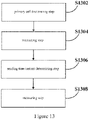
- Figure 13 is a flowchart illustrating a processing procedure example of a measurement method on a user equipment side in a wireless communication system according to an embodiment of the present disclosure.
- the measurement method on the user equipment side may include: a primary cell discovering step S1302, an interacting step S1304, a sending time instant determining step S1306 and a measuring step S1308. Subsequently processing in respective steps is described in detail.
- a primary cell in a macro cell may be discovered and a sending time instant at which the primary cell sends a reference signal is obtained, where the primary cell is a small cell keeping connection with the user equipment all the time.
- the primary cell may be discovered with a default relaxed measurement configuration or a conventional measurement manner, and all small cells in the macro cell support an ON/OFF mechanism.
- the reference signal may include at least one of DRS, CRS and CSI-RS, and may further include any other reference signals which may appear in the future.
- interaction with a macro base station corresponding to the macro cell or a base station corresponding to the primary cell may be performed, so as to obtain a reference signal measurement timing configuration of respective cells in a predetermined range (for example, in the macro cell covering the primary cell) with a time sequence of the primary cell as a reference.
- the reference signal measurement timing configuration include measurement cycles of reference signals of all the small cells in the predetermined range (for example in the macro cell) and offsets between sending time instants at which other small cells send the reference signals and a sending time instant at which the primary cell sends the reference signal.
- the sending time instants at which other small cells send the reference signals may be determined according to the sending time instant at which the primary cell sends the reference signal and the offsets.
- a reference signal of the small cell may be measured by aligning a measuring time instant at which the reference signal of the small cell is measured with a sending time instant at which the small cell sends the reference signal.
- the reference signal may be measured in a so-called relaxed measurement manner so as to reduce power consumption of the user equipment.
- measurement is performed by aligning the measuring time instant with the sending time instant, such that the reference signal can be measured reliably within the measurement cycle and the power consumption of the user equipment can also be reduced in the relaxed measurement manner.
- Figure 14 is a flowchart illustrating a processing procedure example of a management method on a base station side in a wireless communication system according to an embodiment of the present disclosure.
- the management method on the base station side may include a receiving step S1402, an information reading step S1404 and a managing step S1406. Subsequently processing in respective steps is described in detail.
- a radio resource management measurement report reported by user equipment may be received, where the measurement report includes a measurement result for a reference signal of a target cell measured by the user equipment.
- the information reading step S1404 information related to a measurement result with high interference, the interference of which satisfies a predetermined condition, included in the measurement report may be read.
- radio resource management may be performed on the user equipment based on the measurement report, for example mobility management such as adding, deleting, activating and deactivating of component carriers and cell handover, and resource scheduling schemes such as power control, channel allocation and load control.
- mobility management such as adding, deleting, activating and deactivating of component carriers and cell handover
- resource scheduling schemes such as power control, channel allocation and load control.
- the mobility management may be performed on the user equipment based on the information related to the measurement result with high interference included in the measurement report.
- the measurement configuration for the user equipment made by the base station necessarily includes configuration information related to reporting of the measurement result with high interference, and the user equipment returns a corresponding measurement report according to the configuration information.
- the configuration information may include reporting rule configuration information related to reporting of a measurement result of a cell for which the statistical information on the measurement result with high interference satisfies a predetermined condition, a corresponding reporting format and so on.
- an electronic apparatus which may include one or more processors configured to perform the management method and the measurement method on the user equipment side and the management method on the base station side in the wireless communication system according to the embodiments of the present disclosure described above.
- machine executable instructions in a storage medium and a program product may be configured to perform the methods corresponding to the device embodiments, and hence the contents which are not described in detail here may be referred to corresponding descriptions above, and are not repeated here.
- the storage medium includes but not limited to a floppy disk, an optical disk, a magneto-optical disk, a storage card, a memory rod and the like.
- a program constituting the software is installed from a storage medium or a network to a computer with a dedicated hardware structure, e.g., a general purpose personal computer 1500 illustrated in Figure 15 , which can perform various functions when various programs are installed thereon.
- a Central Processing Unit (CPU) 1501 performs various processes according to a program stored in a Read Only Memory (ROM) 1502 or loaded from a storage portion 1508 into a Random Access Memory (RAM) 1503 in which data required when the CPU 1501 performs the various processes is also stored as needed.
- ROM Read Only Memory
- RAM Random Access Memory
- the CPU 1501, the ROM 1502 and the RAM 1503 are connected to each other via a bus 1504 to which an input/output interface 1505 is also connected.
- the following components are connected to the input/output interface 1505: an input portion 1506 including a keyboard, a mouse, etc.; an output portion 1507 including a display, e.g., a Cathode Ray Tube (CRT), a Liquid Crystal Display (LCD), etc., a speaker, etc.; a storage portion 1508 including a hard disk, etc.; and a communication portion 1509 including a network interface card, e.g., an LAN card, a modem, etc.
- the communication portion 1509 performs a communication process over a network, e.g., the Internet.
- a drive 1510 is also connected to the input/output interface 1505 as needed.
- a removable medium 1511 e.g., a magnetic disk, an optical disk, an magneto optical disk, a semiconductor memory, etc., can be installed on the drive 1510 as needed so that a computer program fetched therefrom can be installed into the storage portion 1508 as needed.
- a program constituting the software is installed from a network, e.g., the Internet, etc., or a storage medium, e.g., the removable medium 1511, etc.
- a storage medium will not be limited to the removable medium 1511 illustrated in Figure 15 in which the program is stored and which is distributed separately from the apparatus to provide a user with the program.
- the removable medium 1511 include a magnetic disk (including a Floppy Disk (a registered trademark)), an optical disk (including Compact Disk-Read Only memory (CD-ROM) and a Digital Versatile Disk (DVD)), a magneto optical disk (including a Mini Disk (MD) (a registered trademark)) and a semiconductor memory.
- the storage medium can be the ROM 1502, a hard disk included in the storage portion 1508, etc., in which the program is stored and which is distributed together with the apparatus including the same to the user.
- FIG 16 is a block diagram illustrating a first example of a schematic configuration of an eNB to which the technology of the present disclosure may be applied.
- An eNB 1600 includes one or more antennas 1610 and a base station apparatus 1620. Each antenna 1610 and the base station apparatus 1620 may be connected to each other via an RF cable.
- Each of the antennas 1610 includes a single or multiple antenna elements (such as multiple antenna elements included in a multiple input multiple output (MIMO) antenna), and is used for the base station apparatus 1620 to transmit and receive radio signals.
- the eNB 1600 may include multiple antennas 1610, as illustrated in Figure 16 .
- the multiple antennas 1610 may be compatible with multiple frequency bands used by the eNB 1600.
- Figure 16 illustrates the example in which the eNB 1600 includes the multiple antennas 1610, the eNB 1600 may also include a single antenna 1610.
- the base station apparatus 1620 includes a controller 1621, a memory 1622, a network interface 1623, and a radio communication interface 1625.
- the controller 1621 may be, for example, a CPU or a DSP, and operates various functions of a higher layer of the base station apparatus 1620. For example, the controller 1621 generates a data packet from data in signals processed by the radio communication interface 1625, and transfers the generated packet via the network interface 1623. The controller 1621 may bundle data from multiple base band processors to generate the bundled packet, and transfer the generated bundled packet. The controller 1621 may have logical functions of performing control such as radio resource control, radio bearer control, mobility management, admission control, and scheduling. The control may be performed in corporation with an eNB or a core network node in the vicinity.
- the memory 1622 includes RAM and ROM, and stores a program that is executed by the controller 1621 and various types of control data (such as a terminal list, transmission power data, and scheduling data).
- the network interface 1623 is a communication interface for connecting the base station apparatus 1620 to a core network 1624.
- the controller 1621 may communicate with a core network node or another eNB via the network interface 1623.
- the eNB 1600, and the core network node or the other eNB may be connected to each other through a logical interface (such as an S1 interface and an X2 interface).
- the network interface 1623 may also be a wired communication interface or a radio communication interface for radio backhaul. If the network interface 1623 is a radio communication interface, the network interface 1623 may use a higher frequency band for radio communication than a frequency band used by the radio communication interface 1625.
- the radio communication interface 1625 supports any cellular communication scheme such as Long Term Evolution (LTE) and LTE-Advanced, and provides radio connection to a terminal positioned in a cell of the eNB 1600 via the antenna 1610.
- the radio communication interface 1625 may typically include, for example, a baseband (BB) processor 1626 and an RF circuit 1627.
- the BB processor 1626 may perform, for example, encoding/decoding, modulating/demodulating, and multiplexing/demultiplexing, and performs various types of signal processing of layers (such as LI, medium access control (MAC), radio link control (RLC), and a packet data convergence protocol (PDCP)).
- the BB processor 1626 may have a part or all of the above-described logical functions instead of the controller 1621.
- the BB processor 1626 may be a memory that stores a communication control program, or a module that includes a processor and a related circuit configured to execute the program. Updating the program may allow the functions of the BB processor 1626 to be changed.
- the module may be a card or a blade that is inserted into a slot of the base station apparatus 1620. Alternatively, the module may also be a chip that is mounted on the card or the blade.
- the RF circuit 1627 may include, for example, a mixer, a filter and an amplifier, and transmits and receives radio signals via the antenna 1610.
- the radio communication interface 1625 may include multiple BB processors 1626, as illustrated in Figure 16 .
- the multiple BB processors 1626 may be compatible with multiple frequency bands used by the eNB 1600.
- the radio communication interface 1625 may include the multiple RF circuits 1627, as illustrated in Figure 16 .
- the multiple RF circuits 1627 may be compatible with multiple antenna elements.
- Figure 16 illustrates the example in which the radio communication interface 1625 includes the multiple BB processors 1626 and the multiple RF circuits 1627, the radio communication interface 1625 may also include a single BB processor 1626 or a single RF circuit 1627.
- FIG 17 is a block diagram illustrating a second example of a schematic configuration of an eNB to which the technology of the present disclosure may be applied.
- An eNB 1730 includes one or more antennas 1740, a base station apparatus 1750, and an RRH 1760. Each antenna 1740 and the RRH 1760 may be connected to each other via an RF cable. The base station apparatus 1750 and the RRH 1760 may be connected to each other via a high speed line such as an optical fiber cable.
- Each of the antennas 1740 includes a single or multiple antenna elements (such as multiple antenna elements included in an MIMO antenna), and is used for the RRH 1760 to transmit and receive radio signals.
- the eNB 1730 may include multiple antennas 1740, as illustrated in Figure 17 .
- the multiple antennas 1740 may be compatible with multiple frequency bands used by the eNB 1730.
- Figure 17 illustrates the example in which the eNB 1730 includes the multiple antennas 1740, the eNB 1730 may also include a single antenna 1740.
- the base station apparatus 1750 includes a controller 1751, a memory 1752, a network interface 1753, a radio communication interface 1755, and a connection interface 1757.
- the controller 1751, the memory 1752, and the network interface 1753 are the same as the controller 1621, the memory 1622, and the network interface 1623 described with reference to Figure 16 .
- the radio communication interface 1755 supports any cellular communication scheme such as LTE and LTE-Advanced, and provides radio communication to a terminal positioned in a sector corresponding to the RRH 1760 via the RRH 1760 and the antenna 1740.
- the radio communication interface 1755 may typically include, for example, a BB processor 1756.
- the BB processor 1756 is the same as the BB processor 1626 described with reference to Figure 16 , except the BB processor 1756 is connected to the RF circuit 1764 of the RRH 1760 via the connection interface 1757.
- the radio communication interface 1755 may include multiple BB processors 1756, as illustrated in Figure 17 .
- the multiple BB processors 1756 may be compatible with multiple frequency bands used by the eNB 1730.
- Figure 17 illustrates the example in which the radio communication interface 1755 includes the multiple BB processors 1756, the radio communication interface 1755 may also include a single BB processor 1756.
- connection interface 1757 is an interface for connecting the base station apparatus 1750 (the radio communication interface 1755) to the RRH 1760.
- the connection interface 1757 may also be a communication module for communication in the above-described high speed line that connects the base station apparatus 1750 (the radio communication interface 1755) to the RRH 1760.
- the RRH 1760 includes a connection interface 1761 and a radio communication interface 1763.
- connection interface 1761 is an interface for connecting the RRH 1760 (radio communication interface 1763) to the base station apparatus 1750.
- the connection interface 1761 may also be a communication module for communication in the above-described high speed line.
- the radio communication interface 1763 transmits and receives radio signals via the antenna 1740.
- the radio communication interface 1763 may typically include, for example, the RF circuit 1764.
- the RF circuit 1764 may include, for example, a mixer, a filter and an amplifier, and transmits and receives radio signals via the antenna 1740.
- the radio communication interface 1763 may include multiple RF circuits 1764, as illustrated in Figure 17 .
- the multiple RF circuits 1764 may support multiple antenna elements.
- Figure 17 illustrates the example in which the radio communication interface 1763 includes the multiple RF circuits 1764, the radio communication interface 1763 may also include a single RF circuit 1764.
- the receiving unit 1002 the sending unit 1102 and the receiving unit 1104 described by using Figures 10 and 11 may be implemented by the radio communication interface 1625, and the radio communication interface 1755 and/or the radio communication interface 1763. At least a part of the functions may also be implemented by the controller 1621 and the controller 1751.
- FIG. 18 is a block diagram illustrating an example of a schematic configuration of a smartphone 1800 to which the technology of the present disclosure may be applied.
- the smartphone 1800 includes a processor 1801, a memory 1802, a storage device 1803, an external connection interface 1804, a camera 1806, a sensor 1807, a microphone 1808, an input device 1809, a display device 1810, a speaker 1811, a radio communication interface 1812, one or more antenna switches 1815, one or more antennas 1816, a bus 1817, a battery 1818, and an auxiliary controller 1819.
- the processor 1801 may be, for example, a CPU or a system on a chip (SoC), and controls functions of an application layer and another layer of the smartphone 1800.
- the memory 1802 includes RAM and ROM, and stores a program that is executed by the processor 1801, and data.
- the storage device 1803 may include a storage medium such as a semiconductor memory and a hard disk.
- the external connection interface 1804 is an interface for connecting an external device such as a memory card and a universal serial bus (USB) device to the smartphone 1800.
- the camera 1806 includes an image sensor such as a charge coupled device (CCD) and a complementary metal oxide semiconductor (CMOS), and generates a captured image.
- the sensor 1807 may include a group of sensors such as a measurement sensor, a gyro sensor, a geomagnetic sensor, and an acceleration sensor.
- the microphone 1808 converts sounds that are input to the smartphone 1800 to audio signals.
- the input device 1809 includes, for example, a touch sensor configured to detect touch onto a screen of the display device 1810, a keypad, a keyboard, a button or a switch, and receives an operation or information input from a user.
- the display device 1810 includes a screen such as a liquid crystal display (LCD) and an organic light-emitting diode (OLED) display, and displays an output image of the smartphone 1800.
- the speaker 1811 converts audio signals that are output from the smartphone 1800 to sounds.
- the radio communication interface 1812 supports any cellular communication scheme such as LTE and LTE-Advanced, and performs radio communication.
- the radio communication interface 1812 may typically include, for example, a BB processor 1813 and an RF circuit 1814.
- the BB processor 1813 may perform, for example, encoding/decoding, modulating/demodulating and multiplexing/demultiplexing, and performs various types of signal processing for radio communication.
- the RF circuit 1814 may include, for example, a mixer, a filter, and an amplifier, and transmits and receives radio signals via the antenna 1816.
- the radio communication interface 1812 may be one chip module having the BB processor 1813 and the RF circuit 1814 integrated thereon.
- the radio communication interface 1812 may include multiple BB processors 1813 and the multiple RF circuits 1814, as illustrated in Figure 18 .
- Figure 18 illustrates the example in which the radio communication interface 1812 includes the multiple BB processors 1813 and the multiple RF circuits 1814, the radio communication interface 1812 may also include a single BB processor 1813 or a single RF circuit 1814.
- the radio communication interface 1812 may support another type of radio communication scheme such as a short-distance wireless communication scheme, a near field communication scheme, and a wireless local area network (LAN) scheme.
- the radio communication interface 1812 may include the BB processor 1813 and the RF circuit 1814 for each radio communication scheme.
- Each of the antenna switches 1815 switches connection destinations of the antennas 1816 among multiple circuits (such as circuits for different radio communication schemes) included in the radio communication interface 1812.
- Each of the antennas 1816 includes a single or multiple antenna elements (such as multiple antenna elements included in a MIMO antenna), and is used for the radio communication interface 1812 to transmit and receive radio signals.
- the smartphone 1800 may include multiple antennas 1816, as illustrated in Figure 18 . Although Figure 18 illustrates the example in which the smartphone 1800 includes the multiple antennas 1816, the smartphone 1800 may also include a single antenna 1816.
- the smartphone 1800 may include the antenna 1816 for each radio communication scheme.
- the antenna switches 1815 may be omitted from the configuration of the smartphone 1800.
- the bus 1817 connects the processor 1801, the memory 1802, the storage device 1803, the external connection interface 1804, the camera 1806, the sensor 1807, the microphone 1808, the input device 1809, the display device 1810, the speaker 1811, the radio communication interface 1812 and the auxiliary controller 1819 to each other.
- the battery 1818 supplies power to blocks of the smartphone 1800 illustrated in Figure 18 via feeder lines, which are partially shown as dashed lines in the figure.
- the auxiliary controller 1819 operates a minimum necessary function of the smartphone 1800, for example, in a sleep mode.
- the interacting unit 804 described by using Figure 8 may be implemented by the radio communication interface 1812. At least a part of the functions may also be implemented by the processor 1801 or the auxiliary controller 1819.
- multiple functions included in one unit in the above embodiments may be implemented by separated devices.
- multiple functions implemented by multiple units in the above embodiments may be implemented by separated devices respectively.
- one of the above functions may be implemented by multiple units.
- the steps described in the flow charts include not only processes performed in the sequential order as described chronically, but also processes performed concurrently or separately but not necessarily chronically. Further, even in the steps processed chronically, without saying, the order can be appropriately changed.
Landscapes
- Engineering & Computer Science (AREA)
- Computer Networks & Wireless Communication (AREA)
- Signal Processing (AREA)
- Quality & Reliability (AREA)
- Physics & Mathematics (AREA)
- Electromagnetism (AREA)
- Mobile Radio Communication Systems (AREA)
Claims (11)
- Équipement d'utilisateur dans un système de communication sans fil, comportant une circuiterie (102, 106, 108) de traitement configurée pour :mesurer un signal de référence de découverte d'une cellule cible sur une fréquence sans licence dans une configuration de rythme de mesure de signal de référence et obtenir un résultat de mesure ;juger si une interférence dans le résultat de mesure satisfait une condition prédéterminée, et marquer le résultat de mesure qui satisfait la condition prédéterminée en tant que résultat de mesure à forte interférence ;effectuer un filtrage de couche 3 sur le résultat de mesure ; eteffectuer une gestion de mobilité du dispositif électronique sur la base d'un résultat filtré ; le filtrage de couche 3 étant exprimé comme :
 où Mn indique un résultat de mesure, Fn indique un résultat de mesure filtré actualisé après avoir été soumis à l'opération de filtrage ; Fn-1 indique un précédent résultat de mesure après avoir été soumis à l'opération de filtrage, où F0 est fixé à M1 lorsque le premier résultat de mesure issu de la couche physique est reçu ; et a indique un coefficient prédéterminé d'opération de filtrage ; et la circuiterie de traitement étant en outre configurée pour régler le paramètre a afin de réduire l'influence du résultat de mesure à forte interférence sur la gestion de mobilité.
 - Équipement d'utilisateur selon la revendication 1, la circuiterie de traitement étant en outre configurée en vue d'une resélection de cellule dans un cas où l'équipement d'utilisateur est dans un état inactif, et du signalement du résultat de mesure dans un cas où le dispositif électronique est dans un état connecté.
- Équipement d'utilisateur selon la revendication 2, la circuiterie de traitement étant en outre configurée pour générer un compte rendu de mesure destiné à contenir des informations statistiques sur le résultat de mesure à forte interférence.
- Équipement d'utilisateur selon la revendication 3, la circuiterie de traitement étant en outre configurée pour évaluer s'il convient de rendre compte du résultat de mesure filtré de la cellule cible d'après le résultat de mesure à forte interférence.
- Équipement d'utilisateur selon la revendication 4, la circuiterie de traitement étant en outre configurée pour rendre compte sélectivement du résultat de mesure filtré de la cellule cible et des informations statistiques sur le résultat de mesure à forte interférence à une station de base selon un résultat d'évaluation.
- Équipement d'utilisateur selon l'une quelconque des revendications 2 à 5, la circuiterie de traitement étant en outre configurée pour corriger le résultat de mesure à forte interférence afin d'éliminer l'influence sur la gestion de mobilité due à l'interférence comprise dans le résultat de mesure à forte interférence, et délivrer le résultat de mesure corrigé à la circuiterie de traitement de filtrage.
- Équipement d'utilisateur selon l'une quelconque des revendications 1 à 6, la circuiterie de traitement étant en outre configurée pour mesurer le signal de référence de découverte dans une bande de fréquences sans licence d'évolution à long terme.
- Équipement d'utilisateur selon l'une quelconque des revendications 1 à 7, la circuiterie de traitement étant en outre configurée pour mesurer le signal de référence de découverte en alignant un instant de mesure auquel le signal de référence de découverte est mesuré avec un instant d'émission auquel la cellule cible émet le signal de référence de découverte.
- Équipement d'utilisateur selon la revendication 8, la circuiterie de traitement étant en outre configurée pour mesurer le signal de référence de découverte suivant une méthode de mesure relaxée.
- Équipement d'utilisateur selon la revendication 9, la circuiterie de traitement étant en outre configurée pour mesurer le signal de référence de découverte en alignant une durée de chaque espacement parmi des espacements de mesure dans un espacement de salves de la méthode de mesure relaxée avec l'instant d'émission, en configurant un intervalle entre les espacements de mesure de la méthode de mesure relaxée comme des multiples entiers d'un cycle de mesure du signal de référence de découverte, et en configurant l'espacement de salves de la méthode de mesure relaxée comme des multiples entiers de l'intervalle entre les espacements de mesure.
- Équipement d'utilisateur selon l'une quelconque des revendications 1 à 10, la cellule cible étant une petite cellule prenant en charge un fonctionnement dans une bande de fréquences sans licence d'évolution à long terme.
Priority Applications (1)
| Application Number | Priority Date | Filing Date | Title |
|---|---|---|---|
| EP22202604.9A EP4149153A1 (fr) | 2014-12-22 | 2015-12-22 | Appareil de gestion, appareil de mesure, procédé de gestion, procédé de mesure et dispositif numérique |
Applications Claiming Priority (2)
| Application Number | Priority Date | Filing Date | Title |
|---|---|---|---|
| CN201410808372.7A CN105792243B (zh) | 2014-12-22 | 2014-12-22 | 管理装置、测量装置、管理方法、测量方法和电子设备 |
| PCT/CN2015/098188 WO2016101864A1 (fr) | 2014-12-22 | 2015-12-22 | Appareil de gestion, appareil de mesure, procédé de gestion, procédé de mesure et dispositif numérique |
Related Child Applications (2)
| Application Number | Title | Priority Date | Filing Date |
|---|---|---|---|
| EP22202604.9A Division EP4149153A1 (fr) | 2014-12-22 | 2015-12-22 | Appareil de gestion, appareil de mesure, procédé de gestion, procédé de mesure et dispositif numérique |
| EP22202604.9A Division-Into EP4149153A1 (fr) | 2014-12-22 | 2015-12-22 | Appareil de gestion, appareil de mesure, procédé de gestion, procédé de mesure et dispositif numérique |
Publications (3)
| Publication Number | Publication Date |
|---|---|
| EP3240325A1 EP3240325A1 (fr) | 2017-11-01 |
| EP3240325A4 EP3240325A4 (fr) | 2018-08-22 |
| EP3240325B1 true EP3240325B1 (fr) | 2022-12-14 |
Family
ID=56149272
Family Applications (2)
| Application Number | Title | Priority Date | Filing Date |
|---|---|---|---|
| EP15871932.8A Active EP3240325B1 (fr) | 2014-12-22 | 2015-12-22 | Appareil de mesure, et procédé de mesure |
| EP22202604.9A Withdrawn EP4149153A1 (fr) | 2014-12-22 | 2015-12-22 | Appareil de gestion, appareil de mesure, procédé de gestion, procédé de mesure et dispositif numérique |
Family Applications After (1)
| Application Number | Title | Priority Date | Filing Date |
|---|---|---|---|
| EP22202604.9A Withdrawn EP4149153A1 (fr) | 2014-12-22 | 2015-12-22 | Appareil de gestion, appareil de mesure, procédé de gestion, procédé de mesure et dispositif numérique |
Country Status (6)
| Country | Link |
|---|---|
| US (2) | US10531355B2 (fr) |
| EP (2) | EP3240325B1 (fr) |
| JP (1) | JP6687026B2 (fr) |
| KR (1) | KR102422497B1 (fr) |
| CN (1) | CN105792243B (fr) |
| WO (1) | WO2016101864A1 (fr) |
Families Citing this family (39)
| Publication number | Priority date | Publication date | Assignee | Title |
|---|---|---|---|---|
| CN105792243B (zh) * | 2014-12-22 | 2020-11-06 | 索尼公司 | 管理装置、测量装置、管理方法、测量方法和电子设备 |
| EP3281438B1 (fr) * | 2015-04-09 | 2022-09-28 | Apple Inc. | Capacité de bandes et de radiofréquences d'équipement utilisateur pour intervalle de mesure d'agrégation de porteuses |
| EP3311519B1 (fr) * | 2015-08-13 | 2019-10-09 | Huawei Technologies Co., Ltd. | Détecteur d'interférence pour système de communication sans fil |
| CN108141333B (zh) * | 2015-09-25 | 2021-01-22 | 瑞典爱立信有限公司 | 用于处理无线通信网络中的信号测量的方法和通信终端 |
| WO2017133762A1 (fr) * | 2016-02-02 | 2017-08-10 | Huawei Technologies Co., Ltd. | Systèmes et procédés de planification de ressources et de motifs de pilote pour des terminaux utilisateur dans un réseau sans fil multiutilisateur |
| CN107370779B (zh) * | 2016-05-12 | 2020-12-15 | 华为技术有限公司 | 一种数据传输方法、装置及系统 |
| US10517021B2 (en) | 2016-06-30 | 2019-12-24 | Evolve Cellular Inc. | Long term evolution-primary WiFi (LTE-PW) |
| US11671999B2 (en) * | 2016-12-12 | 2023-06-06 | Dell Products, Lp | Method and apparatus for context aware concurrent data transmission scheduling for pan radio technology |
| CN108882243A (zh) * | 2017-05-10 | 2018-11-23 | 索尼公司 | 用于无线通信系统的电子设备、方法和存储介质 |
| US10425208B2 (en) * | 2017-09-08 | 2019-09-24 | At&T Intellectual Property I, L.P. | Unified indexing framework for reference signals |
| US11736979B2 (en) * | 2017-11-30 | 2023-08-22 | Huawei Technologies Co., Ltd. | Data packet transmission method and apparatus to address a high-latency caused when data is to be transmitted using an unlicensed frequency band |
| CN111165007B (zh) | 2017-12-11 | 2025-02-07 | Oppo广东移动通信有限公司 | 一种配置用户设备测量参数的方法、用户设备及网络设备 |
| JPWO2019142512A1 (ja) * | 2018-01-16 | 2021-01-14 | ソニー株式会社 | 通信装置及び通信方法 |
| CN110418347A (zh) * | 2018-04-27 | 2019-11-05 | 索尼公司 | 用于无线通信的电子设备和方法、计算机可读存储介质 |
| CN110831042B (zh) | 2018-08-09 | 2022-05-31 | 华为技术有限公司 | 测量配置方法与装置 |
| WO2020034242A1 (fr) * | 2018-08-22 | 2020-02-20 | Zte Corporation | Mesure de porteuse composante secondaire (scc) désactivée |
| US12120048B2 (en) | 2018-09-28 | 2024-10-15 | Apple Inc. | Remote interference management reference signal |
| WO2020166029A1 (fr) * | 2019-02-14 | 2020-08-20 | 株式会社Nttドコモ | Équipement d'utilisateur et procédé de mesure |
| CN113039838B (zh) * | 2019-02-14 | 2025-06-06 | 诺基亚技术有限公司 | 基于平稳性的ue节电 |
| EP4026363B1 (fr) * | 2019-10-02 | 2023-12-13 | LG Electronics Inc. | Procédé et appareil pour contrôler la mesure relaxée dans un système de communication sans fil |
| WO2021066422A1 (fr) * | 2019-10-02 | 2021-04-08 | Samsung Electronics Co., Ltd. | Procédé et appareil pour effectuer une mesure de gestion des ressources radio (rrm) dans un système de communication sans fil |
| US11356884B2 (en) * | 2019-10-02 | 2022-06-07 | Lg Electronics Inc. | Method and apparatus for reporting relaxed measurement in a wireless communication system |
| CA3156246A1 (fr) * | 2019-10-03 | 2021-04-08 | Ntt Docomo, Inc. | Terminal et procede de communication |
| WO2021138825A1 (fr) * | 2020-01-08 | 2021-07-15 | Qualcomm Incorporated | Resélection de cellule selon un support à double connectivité |
| CN111278066B (zh) * | 2020-01-16 | 2022-01-28 | 展讯通信(上海)有限公司 | 邻区测量方法、用户设备及计算机可读存储介质 |
| US11477711B2 (en) * | 2020-02-20 | 2022-10-18 | Apple Inc. | Signaling reduction for inter-radio access technology transitions |
| WO2021208085A1 (fr) * | 2020-04-17 | 2021-10-21 | Nec Corporation | Procédés, dispositifs et support de communication |
| CN113572511A (zh) * | 2020-04-29 | 2021-10-29 | 华为技术有限公司 | 一种通信方法、装置及计算机可读存储介质 |
| US12200525B2 (en) * | 2020-05-08 | 2025-01-14 | Qualcomm Incorporated | RRM relaxation for stationary user equipment |
| CN111787563A (zh) * | 2020-06-23 | 2020-10-16 | 广东小天才科技有限公司 | 一种执行放松测量的方法及终端设备 |
| CN111787567B (zh) * | 2020-06-29 | 2022-11-01 | 广东小天才科技有限公司 | 一种确定放松测量参数的方法及终端设备 |
| US12376010B2 (en) * | 2020-12-10 | 2025-07-29 | Mediatek Inc. | Cell search based on spatial-temporal statistical information |
| CN116686327A (zh) * | 2021-01-06 | 2023-09-01 | 苹果公司 | 用于l1-rsrp的测量增强 |
| CN115190499B (zh) * | 2021-04-01 | 2025-10-24 | 大唐移动通信设备有限公司 | 小区间测量上报的配置方法及设备 |
| CN115707050A (zh) * | 2021-08-06 | 2023-02-17 | 维沃移动通信有限公司 | 测量放松方法、装置、终端及网络侧设备 |
| EP4406315A4 (fr) | 2021-09-24 | 2025-05-14 | Apple Inc. | Ncsg pour la mesure de cellule de desserte désactivée |
| CN120676383A (zh) * | 2022-04-21 | 2025-09-19 | Oppo广东移动通信有限公司 | 测量方法、装置、基带芯片、终端及存储介质 |
| CN117040699A (zh) * | 2022-04-28 | 2023-11-10 | 上海朗帛通信技术有限公司 | 一种被用于无线通信的方法和装置 |
| CN118555591B (zh) * | 2024-07-29 | 2024-10-11 | 成都大公博创信息技术有限公司 | 基于无线电监测的指挥调度方法及指挥调度系统 |
Citations (1)
| Publication number | Priority date | Publication date | Assignee | Title |
|---|---|---|---|---|
| US20120214540A1 (en) * | 2011-02-21 | 2012-08-23 | Motorola Mobility, Inc. | Signal Measurement on Component Carriers in Wireless Communication Systems |
Family Cites Families (31)
| Publication number | Priority date | Publication date | Assignee | Title |
|---|---|---|---|---|
| CN101291517B (zh) * | 2007-04-17 | 2012-01-04 | 华为技术有限公司 | 一种测量处理方法及装置 |
| US20120115463A1 (en) * | 2010-11-10 | 2012-05-10 | Research In Motion Limited | Method and device for improved user equipment measurements and reporting |
| US9485749B2 (en) * | 2010-11-10 | 2016-11-01 | Google Technology Holdings LLC | Idle state interference mitigation in wireless communication network |
| CN102480756B (zh) * | 2010-11-29 | 2016-08-03 | 中兴通讯股份有限公司 | 多点协作传输的配置方法和系统 |
| EP2564543B1 (fr) * | 2011-02-11 | 2017-09-06 | MediaTek Inc. | Procédé de traitement préventif des mesures de la qualité rsrq d'équipement d'utilisateur aux fins de coordination des interférences |
| CN103052087B (zh) * | 2011-10-11 | 2017-05-24 | 中兴通讯股份有限公司 | 空闲态用户设备的干扰检测方法及用户设备 |
| CN103096369A (zh) | 2011-11-04 | 2013-05-08 | 华为技术有限公司 | 信道质量测量方法和设备 |
| EP2781043B1 (fr) * | 2011-11-16 | 2015-08-26 | Telefonaktiebolaget LM Ericsson (Publ) | Procédés et systèmes pour mesurer un signal de référence |
| US9094855B2 (en) * | 2012-05-30 | 2015-07-28 | Intel Corporation | Measurement of nodes in coordinated multipoint (CoMP) systems |
| EP2947925A4 (fr) * | 2013-01-18 | 2017-01-18 | Kyocera Corporation | Procédé de commande de communication |
| CN103118396B (zh) * | 2013-01-23 | 2016-03-09 | 华为技术有限公司 | 一种管理小小区网络的方法及基站 |
| CN105027480B (zh) * | 2013-01-25 | 2018-01-16 | Lg电子株式会社 | 用于在无线通信系统中执行初始接入过程的方法和装置 |
| JP6289812B2 (ja) * | 2013-03-25 | 2018-03-07 | 株式会社Nttドコモ | ユーザ端末、無線基地局及び無線通信方法 |
| US10405267B2 (en) * | 2013-04-03 | 2019-09-03 | Interdigital Patent Holdings, Inc. | Cell detection, identification, and measurements for small cell deployments |
| GB2512611A (en) * | 2013-04-03 | 2014-10-08 | Sharp Kk | Wireless telecommunication cell detection technique |
| US9509469B2 (en) * | 2013-04-04 | 2016-11-29 | Futurewei Technologies, Inc. | Device, network, and method for utilizing a downlink discovery reference signal |
| US10660046B2 (en) * | 2013-05-10 | 2020-05-19 | Futurewei Technologies, Inc. | Systems and methods for network adaptation support in wireless network |
| US20160198373A1 (en) * | 2013-07-16 | 2016-07-07 | Telefonaktiebolaget L M Ericsson (Publ) | Mobility Enhancement in Heterogeneous Networks |
| US9749075B2 (en) * | 2013-09-27 | 2017-08-29 | Mediatek Inc. | Methods of discovery and measurements for small cells in OFDM/OFDMA systems |
| US10178567B2 (en) * | 2013-10-31 | 2019-01-08 | Lg Electronics Inc. | Method for performing measurement and wireless equipment thereof |
| US9271205B2 (en) * | 2013-10-31 | 2016-02-23 | Google Technology Holdings LLC | Measurement management in small-cell systems |
| KR101748304B1 (ko) * | 2014-01-24 | 2017-06-16 | 후아웨이 테크놀러지 컴퍼니 리미티드 | 측정 방법, 구성 방법, 관련 장치 및 시스템 |
| KR20150088716A (ko) * | 2014-01-24 | 2015-08-03 | 한국전자통신연구원 | Rrm 측정 방법 및 장치, 그리고 rrm 측정을 위한 신호를 시그널링하는 방법 및 장치 |
| US10044438B2 (en) * | 2014-02-17 | 2018-08-07 | Qualcomm, Incorporated | Carrier sense adaptive transmission (CSAT) measurements in shared spectrum |
| EP3114785A4 (fr) * | 2014-03-04 | 2017-11-29 | LG Electronics Inc. | Procédé de réception d'informations de commande pour recevoir un signal de référence de découverte et appareil associé |
| JP6523250B2 (ja) * | 2014-03-20 | 2019-05-29 | シャープ株式会社 | 端末装置、および、基地局装置 |
| JP6873697B2 (ja) * | 2014-03-20 | 2021-05-19 | シャープ株式会社 | 端末装置、および、基地局装置 |
| JP6649247B2 (ja) * | 2014-03-20 | 2020-02-19 | シャープ株式会社 | 端末装置、および、基地局装置 |
| US9532230B2 (en) * | 2014-06-05 | 2016-12-27 | Texas Instruments Incorporated | Method and apparatus for transmitting LTE waveforms in shared spectrum by carrier sensing |
| US10278090B2 (en) * | 2014-10-30 | 2019-04-30 | Lg Electronics Inc. | Method and apparatus for handling user equipment measurements in case of absence of discovery signals in wireless communication system |
| CN105792243B (zh) * | 2014-12-22 | 2020-11-06 | 索尼公司 | 管理装置、测量装置、管理方法、测量方法和电子设备 |
-
2014
- 2014-12-22 CN CN201410808372.7A patent/CN105792243B/zh active Active
-
2015
- 2015-12-22 WO PCT/CN2015/098188 patent/WO2016101864A1/fr not_active Ceased
- 2015-12-22 US US15/536,402 patent/US10531355B2/en active Active
- 2015-12-22 EP EP15871932.8A patent/EP3240325B1/fr active Active
- 2015-12-22 KR KR1020177017778A patent/KR102422497B1/ko active Active
- 2015-12-22 EP EP22202604.9A patent/EP4149153A1/fr not_active Withdrawn
- 2015-12-22 JP JP2017529313A patent/JP6687026B2/ja active Active
-
2019
- 2019-12-09 US US16/706,843 patent/US11089531B2/en active Active
Patent Citations (1)
| Publication number | Priority date | Publication date | Assignee | Title |
|---|---|---|---|---|
| US20120214540A1 (en) * | 2011-02-21 | 2012-08-23 | Motorola Mobility, Inc. | Signal Measurement on Component Carriers in Wireless Communication Systems |
Also Published As
| Publication number | Publication date |
|---|---|
| KR20170095257A (ko) | 2017-08-22 |
| US11089531B2 (en) | 2021-08-10 |
| EP3240325A4 (fr) | 2018-08-22 |
| JP6687026B2 (ja) | 2020-04-22 |
| WO2016101864A1 (fr) | 2016-06-30 |
| US20200120574A1 (en) | 2020-04-16 |
| EP4149153A1 (fr) | 2023-03-15 |
| JP2017538354A (ja) | 2017-12-21 |
| CN105792243A (zh) | 2016-07-20 |
| KR102422497B1 (ko) | 2022-07-20 |
| CN105792243B (zh) | 2020-11-06 |
| EP3240325A1 (fr) | 2017-11-01 |
| US20180109987A1 (en) | 2018-04-19 |
| US10531355B2 (en) | 2020-01-07 |
Similar Documents
| Publication | Publication Date | Title |
|---|---|---|
| US11089531B2 (en) | Management apparatus, measurement apparatus, management method, measurement method and digital device with layer-3 filtering of measurement results | |
| CN107005357B (zh) | 使用自适应能量检测的无线接入技术共存 | |
| CN106376082B (zh) | 用于无线通信的电子设备以及无线通信方法 | |
| US9232503B2 (en) | Apparatus and method for cell information indication in a wireless network | |
| JP6303000B2 (ja) | ユーザ端末、基地局および無線通信方法 | |
| CN110268736B (zh) | 接收信号强度指示测量方法及其用户设备 | |
| CN106162687B (zh) | 用于无线通信的用户设备侧和基站侧的装置和方法 | |
| JP2017527204A (ja) | 通信システムにおける測定の強化のための方法及び装置 | |
| CN107925448A (zh) | 用于增强的无缝移动性的设备和方法 | |
| CN106549742B (zh) | 无线通信系统中的装置和方法 | |
| EP3142421B1 (fr) | Service de proximité de dispositif à dispositif pour des dispositifs servis par différentes cellules | |
| US20140036708A1 (en) | Method and apparatus for optimizing measurement in a wireless communication system | |
| US10045281B2 (en) | Method, apparatus and system | |
| CN106165467A (zh) | 针对长期演进的授权共享接入 | |
| US20160198374A1 (en) | Detection and recovery from loss of small cell connection | |
| US9241301B2 (en) | Wireless communication system, wireless communication method, mobile station device, and base station device | |
| US20150131646A1 (en) | Method and device for signaling configuration, sending or reception | |
| US20160205577A1 (en) | Channel quality measurement and reporting in a dual connectivity scenario | |
| WO2019041375A1 (fr) | Dispositif électronique, procédé de communication sans fil et support lisible par ordinateur | |
| US11343732B1 (en) | Use of secondary radio to avoid measurement gap on primary air interface connection | |
| KR20210122773A (ko) | 유저장치 |
Legal Events
| Date | Code | Title | Description |
|---|---|---|---|
| STAA | Information on the status of an ep patent application or granted ep patent |
Free format text: STATUS: THE INTERNATIONAL PUBLICATION HAS BEEN MADE |
|
| PUAI | Public reference made under article 153(3) epc to a published international application that has entered the european phase |
Free format text: ORIGINAL CODE: 0009012 |
|
| STAA | Information on the status of an ep patent application or granted ep patent |
Free format text: STATUS: REQUEST FOR EXAMINATION WAS MADE |
|
| 17P | Request for examination filed |
Effective date: 20170722 |
|
| AK | Designated contracting states |
Kind code of ref document: A1 Designated state(s): AL AT BE BG CH CY CZ DE DK EE ES FI FR GB GR HR HU IE IS IT LI LT LU LV MC MK MT NL NO PL PT RO RS SE SI SK SM TR |
|
| AX | Request for extension of the european patent |
Extension state: BA ME |
|
| DAV | Request for validation of the european patent (deleted) | ||
| DAX | Request for extension of the european patent (deleted) | ||
| RIC1 | Information provided on ipc code assigned before grant |
Ipc: H04W 36/04 20090101ALI20180424BHEP Ipc: H04W 84/04 20090101ALN20180424BHEP Ipc: H04W 36/20 20090101ALI20180424BHEP Ipc: H04W 36/30 20090101ALI20180424BHEP Ipc: H04W 24/10 20090101ALI20180424BHEP Ipc: H04W 24/08 20090101AFI20180424BHEP Ipc: H04W 36/38 20090101ALI20180424BHEP Ipc: H04W 16/14 20090101ALI20180424BHEP |
|
| A4 | Supplementary search report drawn up and despatched |
Effective date: 20180724 |
|
| RIC1 | Information provided on ipc code assigned before grant |
Ipc: H04W 36/04 20090101ALI20180718BHEP Ipc: H04W 84/04 20090101ALN20180718BHEP Ipc: H04W 24/10 20090101ALI20180718BHEP Ipc: H04W 24/08 20090101AFI20180718BHEP Ipc: H04W 36/30 20090101ALI20180718BHEP Ipc: H04W 16/14 20090101ALI20180718BHEP Ipc: H04W 36/38 20090101ALI20180718BHEP Ipc: H04W 36/20 20090101ALI20180718BHEP |
|
| STAA | Information on the status of an ep patent application or granted ep patent |
Free format text: STATUS: EXAMINATION IS IN PROGRESS |
|
| 17Q | First examination report despatched |
Effective date: 20190614 |
|
| RAP3 | Party data changed (applicant data changed or rights of an application transferred) |
Owner name: SONY GROUP CORPORATION |
|
| RIC1 | Information provided on ipc code assigned before grant |
Ipc: H04W 84/04 20090101ALN20220506BHEP Ipc: H04W 36/38 20090101ALI20220506BHEP Ipc: H04W 16/14 20090101ALI20220506BHEP Ipc: H04W 36/20 20090101ALI20220506BHEP Ipc: H04W 36/04 20090101ALI20220506BHEP Ipc: H04W 36/30 20090101ALI20220506BHEP Ipc: H04W 24/10 20090101ALI20220506BHEP Ipc: H04W 24/08 20090101AFI20220506BHEP |
|
| RIC1 | Information provided on ipc code assigned before grant |
Ipc: H04W 84/04 20090101ALN20220518BHEP Ipc: H04W 36/38 20090101ALI20220518BHEP Ipc: H04W 16/14 20090101ALI20220518BHEP Ipc: H04W 36/20 20090101ALI20220518BHEP Ipc: H04W 36/04 20090101ALI20220518BHEP Ipc: H04W 36/30 20090101ALI20220518BHEP Ipc: H04W 24/10 20090101ALI20220518BHEP Ipc: H04W 24/08 20090101AFI20220518BHEP |
|
| GRAP | Despatch of communication of intention to grant a patent |
Free format text: ORIGINAL CODE: EPIDOSNIGR1 |
|
| STAA | Information on the status of an ep patent application or granted ep patent |
Free format text: STATUS: GRANT OF PATENT IS INTENDED |
|
| RIC1 | Information provided on ipc code assigned before grant |
Ipc: H04W 84/04 20090101ALN20220620BHEP Ipc: H04W 36/38 20090101ALI20220620BHEP Ipc: H04W 16/14 20090101ALI20220620BHEP Ipc: H04W 36/20 20090101ALI20220620BHEP Ipc: H04W 36/04 20090101ALI20220620BHEP Ipc: H04W 36/30 20090101ALI20220620BHEP Ipc: H04W 24/10 20090101ALI20220620BHEP Ipc: H04W 24/08 20090101AFI20220620BHEP |
|
| INTG | Intention to grant announced |
Effective date: 20220706 |
|
| GRAS | Grant fee paid |
Free format text: ORIGINAL CODE: EPIDOSNIGR3 |
|
| GRAA | (expected) grant |
Free format text: ORIGINAL CODE: 0009210 |
|
| STAA | Information on the status of an ep patent application or granted ep patent |
Free format text: STATUS: THE PATENT HAS BEEN GRANTED |
|
| AK | Designated contracting states |
Kind code of ref document: B1 Designated state(s): AL AT BE BG CH CY CZ DE DK EE ES FI FR GB GR HR HU IE IS IT LI LT LU LV MC MK MT NL NO PL PT RO RS SE SI SK SM TR |
|
| REG | Reference to a national code |
Ref country code: GB Ref legal event code: FG4D |
|
| REG | Reference to a national code |
Ref country code: CH Ref legal event code: EP |
|
| REG | Reference to a national code |
Ref country code: DE Ref legal event code: R096 Ref document number: 602015081971 Country of ref document: DE |
|
| REG | Reference to a national code |
Ref country code: IE Ref legal event code: FG4D |
|
| REG | Reference to a national code |
Ref country code: AT Ref legal event code: REF Ref document number: 1538400 Country of ref document: AT Kind code of ref document: T Effective date: 20230115 |
|
| REG | Reference to a national code |
Ref country code: LT Ref legal event code: MG9D |
|
| REG | Reference to a national code |
Ref country code: NL Ref legal event code: MP Effective date: 20221214 |
|
| PG25 | Lapsed in a contracting state [announced via postgrant information from national office to epo] |
Ref country code: SE Free format text: LAPSE BECAUSE OF FAILURE TO SUBMIT A TRANSLATION OF THE DESCRIPTION OR TO PAY THE FEE WITHIN THE PRESCRIBED TIME-LIMIT Effective date: 20221214 Ref country code: NO Free format text: LAPSE BECAUSE OF FAILURE TO SUBMIT A TRANSLATION OF THE DESCRIPTION OR TO PAY THE FEE WITHIN THE PRESCRIBED TIME-LIMIT Effective date: 20230314 Ref country code: LT Free format text: LAPSE BECAUSE OF FAILURE TO SUBMIT A TRANSLATION OF THE DESCRIPTION OR TO PAY THE FEE WITHIN THE PRESCRIBED TIME-LIMIT Effective date: 20221214 Ref country code: FI Free format text: LAPSE BECAUSE OF FAILURE TO SUBMIT A TRANSLATION OF THE DESCRIPTION OR TO PAY THE FEE WITHIN THE PRESCRIBED TIME-LIMIT Effective date: 20221214 |
|
| REG | Reference to a national code |
Ref country code: AT Ref legal event code: MK05 Ref document number: 1538400 Country of ref document: AT Kind code of ref document: T Effective date: 20221214 |
|
| PG25 | Lapsed in a contracting state [announced via postgrant information from national office to epo] |
Ref country code: RS Free format text: LAPSE BECAUSE OF FAILURE TO SUBMIT A TRANSLATION OF THE DESCRIPTION OR TO PAY THE FEE WITHIN THE PRESCRIBED TIME-LIMIT Effective date: 20221214 Ref country code: LV Free format text: LAPSE BECAUSE OF FAILURE TO SUBMIT A TRANSLATION OF THE DESCRIPTION OR TO PAY THE FEE WITHIN THE PRESCRIBED TIME-LIMIT Effective date: 20221214 Ref country code: HR Free format text: LAPSE BECAUSE OF FAILURE TO SUBMIT A TRANSLATION OF THE DESCRIPTION OR TO PAY THE FEE WITHIN THE PRESCRIBED TIME-LIMIT Effective date: 20221214 Ref country code: GR Free format text: LAPSE BECAUSE OF FAILURE TO SUBMIT A TRANSLATION OF THE DESCRIPTION OR TO PAY THE FEE WITHIN THE PRESCRIBED TIME-LIMIT Effective date: 20230315 |
|
| PG25 | Lapsed in a contracting state [announced via postgrant information from national office to epo] |
Ref country code: NL Free format text: LAPSE BECAUSE OF FAILURE TO SUBMIT A TRANSLATION OF THE DESCRIPTION OR TO PAY THE FEE WITHIN THE PRESCRIBED TIME-LIMIT Effective date: 20221214 |
|
| P01 | Opt-out of the competence of the unified patent court (upc) registered |
Effective date: 20230527 |
|
| PG25 | Lapsed in a contracting state [announced via postgrant information from national office to epo] |
Ref country code: SM Free format text: LAPSE BECAUSE OF FAILURE TO SUBMIT A TRANSLATION OF THE DESCRIPTION OR TO PAY THE FEE WITHIN THE PRESCRIBED TIME-LIMIT Effective date: 20221214 Ref country code: RO Free format text: LAPSE BECAUSE OF FAILURE TO SUBMIT A TRANSLATION OF THE DESCRIPTION OR TO PAY THE FEE WITHIN THE PRESCRIBED TIME-LIMIT Effective date: 20221214 Ref country code: PT Free format text: LAPSE BECAUSE OF FAILURE TO SUBMIT A TRANSLATION OF THE DESCRIPTION OR TO PAY THE FEE WITHIN THE PRESCRIBED TIME-LIMIT Effective date: 20230414 Ref country code: ES Free format text: LAPSE BECAUSE OF FAILURE TO SUBMIT A TRANSLATION OF THE DESCRIPTION OR TO PAY THE FEE WITHIN THE PRESCRIBED TIME-LIMIT Effective date: 20221214 Ref country code: EE Free format text: LAPSE BECAUSE OF FAILURE TO SUBMIT A TRANSLATION OF THE DESCRIPTION OR TO PAY THE FEE WITHIN THE PRESCRIBED TIME-LIMIT Effective date: 20221214 Ref country code: CZ Free format text: LAPSE BECAUSE OF FAILURE TO SUBMIT A TRANSLATION OF THE DESCRIPTION OR TO PAY THE FEE WITHIN THE PRESCRIBED TIME-LIMIT Effective date: 20221214 Ref country code: AT Free format text: LAPSE BECAUSE OF FAILURE TO SUBMIT A TRANSLATION OF THE DESCRIPTION OR TO PAY THE FEE WITHIN THE PRESCRIBED TIME-LIMIT Effective date: 20221214 |
|
| REG | Reference to a national code |
Ref country code: CH Ref legal event code: PL |
|
| REG | Reference to a national code |
Ref country code: BE Ref legal event code: MM Effective date: 20221231 |
|
| PG25 | Lapsed in a contracting state [announced via postgrant information from national office to epo] |
Ref country code: SK Free format text: LAPSE BECAUSE OF FAILURE TO SUBMIT A TRANSLATION OF THE DESCRIPTION OR TO PAY THE FEE WITHIN THE PRESCRIBED TIME-LIMIT Effective date: 20221214 Ref country code: PL Free format text: LAPSE BECAUSE OF FAILURE TO SUBMIT A TRANSLATION OF THE DESCRIPTION OR TO PAY THE FEE WITHIN THE PRESCRIBED TIME-LIMIT Effective date: 20221214 Ref country code: LU Free format text: LAPSE BECAUSE OF NON-PAYMENT OF DUE FEES Effective date: 20221222 Ref country code: IS Free format text: LAPSE BECAUSE OF FAILURE TO SUBMIT A TRANSLATION OF THE DESCRIPTION OR TO PAY THE FEE WITHIN THE PRESCRIBED TIME-LIMIT Effective date: 20230414 Ref country code: AL Free format text: LAPSE BECAUSE OF FAILURE TO SUBMIT A TRANSLATION OF THE DESCRIPTION OR TO PAY THE FEE WITHIN THE PRESCRIBED TIME-LIMIT Effective date: 20221214 |
|
| REG | Reference to a national code |
Ref country code: DE Ref legal event code: R097 Ref document number: 602015081971 Country of ref document: DE |
|
| PG25 | Lapsed in a contracting state [announced via postgrant information from national office to epo] |
Ref country code: MC Free format text: LAPSE BECAUSE OF FAILURE TO SUBMIT A TRANSLATION OF THE DESCRIPTION OR TO PAY THE FEE WITHIN THE PRESCRIBED TIME-LIMIT Effective date: 20221214 |
|
| PLBE | No opposition filed within time limit |
Free format text: ORIGINAL CODE: 0009261 |
|
| STAA | Information on the status of an ep patent application or granted ep patent |
Free format text: STATUS: NO OPPOSITION FILED WITHIN TIME LIMIT |
|
| PG25 | Lapsed in a contracting state [announced via postgrant information from national office to epo] |
Ref country code: LI Free format text: LAPSE BECAUSE OF NON-PAYMENT OF DUE FEES Effective date: 20221231 Ref country code: IE Free format text: LAPSE BECAUSE OF NON-PAYMENT OF DUE FEES Effective date: 20221222 Ref country code: DK Free format text: LAPSE BECAUSE OF FAILURE TO SUBMIT A TRANSLATION OF THE DESCRIPTION OR TO PAY THE FEE WITHIN THE PRESCRIBED TIME-LIMIT Effective date: 20221214 Ref country code: CH Free format text: LAPSE BECAUSE OF NON-PAYMENT OF DUE FEES Effective date: 20221231 |
|
| 26N | No opposition filed |
Effective date: 20230915 |
|
| PG25 | Lapsed in a contracting state [announced via postgrant information from national office to epo] |
Ref country code: SI Free format text: LAPSE BECAUSE OF FAILURE TO SUBMIT A TRANSLATION OF THE DESCRIPTION OR TO PAY THE FEE WITHIN THE PRESCRIBED TIME-LIMIT Effective date: 20221214 Ref country code: BE Free format text: LAPSE BECAUSE OF NON-PAYMENT OF DUE FEES Effective date: 20221231 |
|
| PG25 | Lapsed in a contracting state [announced via postgrant information from national office to epo] |
Ref country code: FR Free format text: LAPSE BECAUSE OF NON-PAYMENT OF DUE FEES Effective date: 20230214 |
|
| PG25 | Lapsed in a contracting state [announced via postgrant information from national office to epo] |
Ref country code: HU Free format text: LAPSE BECAUSE OF FAILURE TO SUBMIT A TRANSLATION OF THE DESCRIPTION OR TO PAY THE FEE WITHIN THE PRESCRIBED TIME-LIMIT; INVALID AB INITIO Effective date: 20151222 |
|
| PG25 | Lapsed in a contracting state [announced via postgrant information from national office to epo] |
Ref country code: CY Free format text: LAPSE BECAUSE OF FAILURE TO SUBMIT A TRANSLATION OF THE DESCRIPTION OR TO PAY THE FEE WITHIN THE PRESCRIBED TIME-LIMIT Effective date: 20221214 |
|
| PG25 | Lapsed in a contracting state [announced via postgrant information from national office to epo] |
Ref country code: MK Free format text: LAPSE BECAUSE OF FAILURE TO SUBMIT A TRANSLATION OF THE DESCRIPTION OR TO PAY THE FEE WITHIN THE PRESCRIBED TIME-LIMIT Effective date: 20221214 Ref country code: IT Free format text: LAPSE BECAUSE OF FAILURE TO SUBMIT A TRANSLATION OF THE DESCRIPTION OR TO PAY THE FEE WITHIN THE PRESCRIBED TIME-LIMIT Effective date: 20221214 |
|
| PG25 | Lapsed in a contracting state [announced via postgrant information from national office to epo] |
Ref country code: BG Free format text: LAPSE BECAUSE OF FAILURE TO SUBMIT A TRANSLATION OF THE DESCRIPTION OR TO PAY THE FEE WITHIN THE PRESCRIBED TIME-LIMIT Effective date: 20221214 |
|
| PG25 | Lapsed in a contracting state [announced via postgrant information from national office to epo] |
Ref country code: MT Free format text: LAPSE BECAUSE OF FAILURE TO SUBMIT A TRANSLATION OF THE DESCRIPTION OR TO PAY THE FEE WITHIN THE PRESCRIBED TIME-LIMIT Effective date: 20221214 |
|
| PG25 | Lapsed in a contracting state [announced via postgrant information from national office to epo] |
Ref country code: TR Free format text: LAPSE BECAUSE OF FAILURE TO SUBMIT A TRANSLATION OF THE DESCRIPTION OR TO PAY THE FEE WITHIN THE PRESCRIBED TIME-LIMIT Effective date: 20221214 |
|
| PGFP | Annual fee paid to national office [announced via postgrant information from national office to epo] |
Ref country code: DE Payment date: 20251126 Year of fee payment: 11 |
|
| PGFP | Annual fee paid to national office [announced via postgrant information from national office to epo] |
Ref country code: GB Payment date: 20251120 Year of fee payment: 11 |