EP3240671B1 - Impression en trois dimensions d'objets comprenant des orifices de respiration - Google Patents
Impression en trois dimensions d'objets comprenant des orifices de respiration Download PDFInfo
- Publication number
- EP3240671B1 EP3240671B1 EP15831114.2A EP15831114A EP3240671B1 EP 3240671 B1 EP3240671 B1 EP 3240671B1 EP 15831114 A EP15831114 A EP 15831114A EP 3240671 B1 EP3240671 B1 EP 3240671B1
- Authority
- EP
- European Patent Office
- Prior art keywords
- build
- carrier
- polymerizable liquid
- liquid
- build surface
- Prior art date
- Legal status (The legal status is an assumption and is not a legal conclusion. Google has not performed a legal analysis and makes no representation as to the accuracy of the status listed.)
- Active
Links
Images







Classifications
-
- B—PERFORMING OPERATIONS; TRANSPORTING
- B29—WORKING OF PLASTICS; WORKING OF SUBSTANCES IN A PLASTIC STATE IN GENERAL
- B29C—SHAPING OR JOINING OF PLASTICS; SHAPING OF MATERIAL IN A PLASTIC STATE, NOT OTHERWISE PROVIDED FOR; AFTER-TREATMENT OF THE SHAPED PRODUCTS, e.g. REPAIRING
- B29C64/00—Additive manufacturing, i.e. manufacturing of three-dimensional [3D] objects by additive deposition, additive agglomeration or additive layering, e.g. by 3D printing, stereolithography or selective laser sintering
- B29C64/10—Processes of additive manufacturing
- B29C64/106—Processes of additive manufacturing using only liquids or viscous materials, e.g. depositing a continuous bead of viscous material
- B29C64/124—Processes of additive manufacturing using only liquids or viscous materials, e.g. depositing a continuous bead of viscous material using layers of liquid which are selectively solidified
-
- B—PERFORMING OPERATIONS; TRANSPORTING
- B29—WORKING OF PLASTICS; WORKING OF SUBSTANCES IN A PLASTIC STATE IN GENERAL
- B29C—SHAPING OR JOINING OF PLASTICS; SHAPING OF MATERIAL IN A PLASTIC STATE, NOT OTHERWISE PROVIDED FOR; AFTER-TREATMENT OF THE SHAPED PRODUCTS, e.g. REPAIRING
- B29C35/00—Heating, cooling or curing, e.g. crosslinking or vulcanising; Apparatus therefor
- B29C35/02—Heating or curing, e.g. crosslinking or vulcanizing during moulding, e.g. in a mould
-
- B—PERFORMING OPERATIONS; TRANSPORTING
- B29—WORKING OF PLASTICS; WORKING OF SUBSTANCES IN A PLASTIC STATE IN GENERAL
- B29C—SHAPING OR JOINING OF PLASTICS; SHAPING OF MATERIAL IN A PLASTIC STATE, NOT OTHERWISE PROVIDED FOR; AFTER-TREATMENT OF THE SHAPED PRODUCTS, e.g. REPAIRING
- B29C41/00—Shaping by coating a mould, core or other substrate, i.e. by depositing material and stripping-off the shaped article; Apparatus therefor
- B29C41/02—Shaping by coating a mould, core or other substrate, i.e. by depositing material and stripping-off the shaped article; Apparatus therefor for making articles of definite length, i.e. discrete articles
-
- B—PERFORMING OPERATIONS; TRANSPORTING
- B29—WORKING OF PLASTICS; WORKING OF SUBSTANCES IN A PLASTIC STATE IN GENERAL
- B29C—SHAPING OR JOINING OF PLASTICS; SHAPING OF MATERIAL IN A PLASTIC STATE, NOT OTHERWISE PROVIDED FOR; AFTER-TREATMENT OF THE SHAPED PRODUCTS, e.g. REPAIRING
- B29C64/00—Additive manufacturing, i.e. manufacturing of three-dimensional [3D] objects by additive deposition, additive agglomeration or additive layering, e.g. by 3D printing, stereolithography or selective laser sintering
- B29C64/10—Processes of additive manufacturing
- B29C64/106—Processes of additive manufacturing using only liquids or viscous materials, e.g. depositing a continuous bead of viscous material
-
- B—PERFORMING OPERATIONS; TRANSPORTING
- B33—ADDITIVE MANUFACTURING TECHNOLOGY
- B33Y—ADDITIVE MANUFACTURING, i.e. MANUFACTURING OF THREE-DIMENSIONAL [3D] OBJECTS BY ADDITIVE DEPOSITION, ADDITIVE AGGLOMERATION OR ADDITIVE LAYERING, e.g. BY 3D PRINTING, STEREOLITHOGRAPHY OR SELECTIVE LASER SINTERING
- B33Y70/00—Materials specially adapted for additive manufacturing
-
- B—PERFORMING OPERATIONS; TRANSPORTING
- B29—WORKING OF PLASTICS; WORKING OF SUBSTANCES IN A PLASTIC STATE IN GENERAL
- B29C—SHAPING OR JOINING OF PLASTICS; SHAPING OF MATERIAL IN A PLASTIC STATE, NOT OTHERWISE PROVIDED FOR; AFTER-TREATMENT OF THE SHAPED PRODUCTS, e.g. REPAIRING
- B29C67/00—Shaping techniques not covered by groups B29C39/00 - B29C65/00, B29C70/00 or B29C73/00
-
- B—PERFORMING OPERATIONS; TRANSPORTING
- B33—ADDITIVE MANUFACTURING TECHNOLOGY
- B33Y—ADDITIVE MANUFACTURING, i.e. MANUFACTURING OF THREE-DIMENSIONAL [3D] OBJECTS BY ADDITIVE DEPOSITION, ADDITIVE AGGLOMERATION OR ADDITIVE LAYERING, e.g. BY 3D PRINTING, STEREOLITHOGRAPHY OR SELECTIVE LASER SINTERING
- B33Y10/00—Processes of additive manufacturing
-
- B—PERFORMING OPERATIONS; TRANSPORTING
- B33—ADDITIVE MANUFACTURING TECHNOLOGY
- B33Y—ADDITIVE MANUFACTURING, i.e. MANUFACTURING OF THREE-DIMENSIONAL [3D] OBJECTS BY ADDITIVE DEPOSITION, ADDITIVE AGGLOMERATION OR ADDITIVE LAYERING, e.g. BY 3D PRINTING, STEREOLITHOGRAPHY OR SELECTIVE LASER SINTERING
- B33Y30/00—Apparatus for additive manufacturing; Details thereof or accessories therefor
Definitions
- the present invention concerns methods and apparatus for the fabrication of three-dimensional objects from liquid materials, where the objects have a hollow portion.
- construction of a three-dimensional object is performed in a step-wise or layer-by-layer manner.
- layer formation is performed through solidification of photo curable resin under the action of visible or UV light irradiation.
- Two techniques are known: one in which new layers are formed at the top surface of the growing object; the other in which new layers are formed at the bottom surface of the growing object.
- an elastic separation layer is used to achieve "non-destructive" separation of solidified material at the bottom construction plane.
- Other approaches such as the B9CreatorTM 3-dimensional printer marketed by B9Creations of Deadwood, South Dakota, USA, employ a sliding build plate. See, e.g., M. Joyce, US Patent App. 2013/0292862 and Y. Chen et al., US Patent App. 2013/0295212 (both Nov. 7, 2013 ); see also Y. Pan et al., J. Manufacturing Sci. and Eng. 134, 051011-1 (Oct. 2012 ). Such approaches introduce a mechanical step that may complicate the apparatus, slow the method, and/or potentially distort the end product.
- WO 2012/150497 discloses a method for making three-dimensional objects formed by a plurality of superimposed layers of a fluid photopolymer suited to solidify through polymerization following a stimulating action, comprising the following operations: - making the fluid photopolymer flow on a supporting surface exposed to stimulation in such a way as to define a layer adjacent to the previous layer; - selectively exposing the layer to stimulation in one or more predefined areas; - repeating the step regarding flow and exposure for each successive layer of the three-dimensional object.
- the method also includes an operation intended to reduce pressure in the environment where the three-dimensional object is manufactured compared to the external atmospheric pressure, prior to said operations regarding flow and exposure.
- WO 2014/126834 discloses a method of forming a three-dimensional object by (a) providing a carrier and a build plate, the build plate comprising a semipermeable member, the semipermeable member comprising a build surface with the build surface and the carrier defining a build region therebetween, and with the build surface in fluid communication by way of the semipermeable member with a source of polymerization inhibitor; (b) filling the build region with a polymerizable liquid, the polymerizable liquid contacting the build surface; (c) irradiating the build region through the build plate to produce a solid polymerized region in the build region, while forming or maintaining a liquid film release layer comprised of the polymerizable liquid formed between the solid polymerized region and the build surface, the polymerization of which liquid film is inhibited by the polymerization inhibitor; and (d) advancing the carrier with the polymerized region adhered thereto away from the build surface on the build plate to create a subsequent build region between the polymerized region and the
- Described herein are methods, systems and apparatus (including associated control methods, systems and apparatus), for the production of a three-dimensional object by additive manufacturing.
- the method is carried out continuously.
- the three-dimensional object is produced from a liquid interface.
- continuous liquid interphase printing A schematic representation is given in Figure 1 herein.
- a portion of the three dimensional object is hollow: That is, the object has a circumferential wall and an internal cavity contained within that wall.
- the wall has an upper portion and a lower portion.
- the method includes the step of forming a breathing orifice in the wall (preferably in the wall upper portion) while forming the three-dimensional object.
- the filling, irradiating, and/or advancing steps are carried out while also concurrently: (i) continuously maintaining a dead zone of polymerizable liquid in contact with said build surface, and (ii) continuously maintaining a gradient of polymerization zone between said dead zone and said solid polymer and in contact with each thereof, said gradient of polymerization zone comprising said polymerizable liquid in partially cured form.
- the dead zone and gradient of polymerization zone may be maintained through some or all of the formation of the object being made, for example (and in some embodiments) for a time of at least 5, 10, 20, or 30 seconds, and in some embodiments for a time of at least 1 or 2 minutes.
- a further aspect of the invention is an apparatus for forming a three-dimensional object from a polymerizable liquid.
- the apparatus comprises:
- the apparatus further comprises a siphon line connected to the breathing orifice and configured to interconnect the breathing orifice with the liquid polymer supply.
- a priming pump may be included on the siphon line to prime the siphon line.
- the apparatus further comprises a polymerizable liquid supply in fluid communication with the breathing orifice, and a liquid pressure regulator operatively associated with the breathing orifice and the polymerizable liquid supply.
- the device may otherwise be oriented (rotated 90 degrees or at other orientations) and the spatially relative descriptors used herein interpreted accordingly.
- the terms “upwardly,” “downwardly,” “vertical,” “horizontal” and the like are used herein for the purpose of explanation only, unless specifically indicated otherwise.
- first, second, etc. may be used herein to describe various elements, components, regions, layers and/or sections, these elements, components, regions, layers and/or sections should not be limited by these terms. Rather, these terms are only used to distinguish one element, component, region, layer and/or section, from another element, component, region, layer and/or section. Thus, a first element, component, region, layer or section discussed herein could be termed a second element, component, region, layer or section without departing from the teachings of the present invention.
- the sequence of operations (or steps) is not limited to the order presented in the claims or figures unless specifically indicated otherwise.
- the liquid can include a monomer, particularly photopolymerizable and/or free radical polymerizable monomers, and a suitable initiator such as a free radical initiator, and combinations thereof.
- suitable initiator such as a free radical initiator
- examples include, but are not limited to, acrylics, methacrylics, acrylamides, styrenics, olefins, halogenated olefins, cyclic alkenes, maleic anhydride, alkenes, alkynes, carbon monoxide, functionalized oligomers, multifunctional cute site monomers, functionalized PEGs, etc., including combinations thereof.
- liquid resins, monomers and initiators include but are not limited to those set forth in US Patents Nos. 8,232,043 ; 8,119,214 ; 7,935,476 ; 7,767,728 ; 7,649,029 ; WO 2012129968 A1 ; CN 102715751 A ; JP 2012210408 A .
- the polymerizable liquid comprises a free radical polymerizable liquid (in which case an inhibitor may be oxygen as described below), in other embodiments the polymerizable liquid comprises an acid catalyzed, or cationically polymerized, polymerizable liquid. In such embodiments the polymerizable liquid comprises monomers contain groups suitable for acid catalysis, such as epoxide groups, vinyl ether groups, etc..
- suitable monomers include olefins such as methoxyethene, 4-methoxystyrene, styrene, 2-methylprop-1-ene, 1,3-butadiene, etc.; heterocycloic monomers (including lactones, lactams, and cyclic amines) such as oxirane, thietane, tetrahydrofuran, oxazoline, 1,3, dioxepane, oxetan-2-one, etc., and combinations thereof.
- olefins such as methoxyethene, 4-methoxystyrene, styrene, 2-methylprop-1-ene, 1,3-butadiene, etc.
- heterocycloic monomers including lactones, lactams, and cyclic amines
- a suitable (generally ionic or non-ionic) photoacid generator (PAG) is included in the acid catalyzed polymerizable liquid, examples of which include, but are not limited to onium salts, sulfonium and iodonium salts, etc., such as diphenyl iodide hexafluorophosphate, diphenyl iodide hexafluoroarsenate, diphenyl iodide hexafluoroantimonate, diphenyl p-methoxyphenyl triflate, diphenyl p-toluenyl triflate, diphenyl p-isobutylphenyl triflate, diphenyl p-tert-butylphenyl triflate, triphenylsulfonium hexafluororphosphate, triphenylsulfonium hexafluoroarsenate, triphenylsulfonium
- suitable resins includes photocurable hydrogels like poly(ethylene glycols) (PEG) and gelatins.
- PEG hydrogels have been used to deliver a variety of biologicals, including Growth factors; however, a great challenge facing PEG hydrogels crosslinked by chain growth polymerizations is the potential for irreversible protein damage.
- Conditions to maximize release of the biologicals from photopolymerized PEG diacrylate hydrogels can be enhanced by inclusion of affinity binding peptide sequences in the monomer resin solutions, prior to photopolymerization allowing sustained delivery.
- Gelatin is a biopolymer frequently used in food, cosmetic, pharmaceutical and photographic industries. It is obtained by thermal denaturation or chemical and physical degradation of collagen.
- gelatin There are three kinds of gelatin, including those found in animals, fish and humans. Gelatin from the skin of cold water fish is considered safe to use in pharmaceutical applications. UV or visible light can be used to crosslink appropriately modified gelatin. Methods for crosslinking gelatin include cure derivatives from dyes such as Rose Bengal.
- Photocurable silicone resins A suitable resin includes photocurable silicones.
- UV cure silicone rubber such as SilioprenTM UV Cure Silicone Rubber can be used as can LOCTITETM Cure Silicone adhesives sealants.
- Applications include optical instruments, medical and surgical equipment, exterior lighting and enclosures, electrical connectors / sensors, fiber optics and gaskets.
- Biodegradable resins are particularly important for implantable devices to deliver drugs or for temporary performance applications, like biodegradable screws and stents ( US patents 7,919,162 ; 6,932,930 ).
- Biodegradable copolymers of lactic acid and glycolic acid (PLGA) can be dissolved in PEG dimethacrylate to yield a transparent resin suitable for use.
- Polycaprolactone and PLGA oligomers can be functionalized with acrylic or methacrylic groups to allow them to be effective resins for use.
- Photocurable polyurethanes A particularly useful resin is photocurable polyurethanes.
- a photopolymerizable polyurethane composition comprising (1) a polyurethane based on an aliphatic diisocyanate, poly(hexamethylene isophthalate glycol) and, optionally, 1,4-butanediol; (2) a polyfunctional acrylic ester; (3) a photoinitiator; and (4) an anti-oxidant, can be formulated so that it provides a hard, abrasion-resistant, and stain-resistant material ( US Patent 4,337,130 ).
- Photocurable thermoplastic polyurethane elastomers incorporate photoreactive diacetylene diols as chain extenders.
- High performance resins are used. Such high performance resins may sometimes require the use of heating to melt and/or reduce the viscosity thereof, as noted above and discussed further below. Examples of such resins include, but are not limited to, resins for those materials sometimes referred to as liquid crystalline polymers of esters, ester-imide, and ester-amide oligomers, as described in US Patents Nos. 7,507,784 ; 6,939,940 .
- thermoset resins are sometimes employed as high-temperature thermoset resins, in the present invention they further comprise a suitable photoinitiator such as benzophenone, anthraquinone, amd fluoroenone initiators (including derivatives thereof), to initiate cross-linking on irradiation, as discussed further below.
- a suitable photoinitiator such as benzophenone, anthraquinone, amd fluoroenone initiators (including derivatives thereof), to initiate cross-linking on irradiation, as discussed further below.
- Particularly useful resins for dental applications include EnvisionTEC's Clear Guide, EnvisionTEC's E-Denstone Material.
- Particularly useful resins for hearing aid industries include EnvisionTEC's e-Shell 300 Series of resins.
- Particularly useful resins include EnvisionTEC's HTM140IV High Temperature Mold Material for use directly with vulcanized rubber in molding / casting applications.
- a particularly useful material for making tough and stiff parts includes EnvisionTEC's RC31 resin.
- a particulary useful resin for investment casting applications includes EnvisionTEC's Easy Cast EC500.
- the liquid resin or polymerizable material can have solid particles suspended or dispersed therein. Any suitable solid particle can be used, depending upon the end product being fabricated.
- the particles can be metallic, organic/polymeric, inorganic, or composites or mixtures thereof.
- the particles can be nonconductive, semi-conductive, or conductive (including metallic and non-metallic or polymer conductors); and the particles can be magnetic, ferromagnetic, paramagnetic, or nonmagnetic.
- the particles can be of any suitable shape, including spherical, elliptical, cylindrical, etc.
- the particles can comprise an active agent or detectable compound as described below, though these may also be provided dissolved solubilized in the liquid resin as also discussed below.
- the resin or polymerizable material may contain a dispersing agent, such as an ionic surfactant, a non-ionic surfactant, a block copolymer, or the like.
- the liquid resin can have additional ingredients solubilized therein, including pigments, dyes, active compounds or pharmaceutical compounds, detectable compounds (e.g., fluorescent, phosphorescent, radioactive), etc., again depending upon the particular purpose of the product being fabricated.
- additional ingredients include, but are not limited to, proteins, peptides, nucleic acids (DNA, RNA) such as siRNA, sugars, small organic compounds (drugs and drug-like compounds), etc., including combinations thereof.
- Inhibitors of polymerization may be in the form of a liquid or a gas.
- gas inhibitors are preferred.
- the specific inhibitor will depend upon the monomer being polymerized and the polymerization reaction.
- the inhibitor can conveniently be oxygen, which can be provided in the form of a gas such as air, a gas enriched in oxygen (optionally but in some embodiments preferably containing additional inert gases to reduce combustibility thereof), or in some embodiments pure oxygen gas.
- the inhibitor can be a base such as ammonia, trace amines (e.g . methyl amine, ethyl amine, di and trialkyl amines such as dimethyl amine, diethyl amine, trimethyl amine, triethyl amine, etc.), or carbon dioxide, including mixtures or combinations thereof.
- Polymerizable liquids carrying live cells may carry live cells as "particles" therein.
- Such polymerizable liquids are generally aqueous, and may be oxygenated, and may be considered as "emulsions" where the live cells are the discrete phase.
- Suitable live cells may be plant cells ( e.g ., monocot, dicot), animal cells ( e.g., mammalian, avian, amphibian, reptile cells), microbial cells (e.g., prokaryote, eukaryote, protozoal, etc.), etc.
- the cells may be of differentiated cells from or corresponding to any type of tissue (e.g ., blood, cartilage, bone, muscle, endocrine gland, exocrine gland, epithelial, endothelial, etc.), or may be undifferentiated cells such as stem cells or progenitor cells.
- the polymerizable liquid can be one that forms a hydrogel, including but not limited to those described in US Patents Nos. 7,651,683 ; 7,651,682 ; 7,556,490 ; 6,602,975 ; 5,836,313 ; etc.
- FIG. 2 A non-limiting embodiment of an apparatus of the invention is shown in Figure 2 . It comprises a radiation source 11 such as a digital light processor (DLP) providing electromagnetic radiation 12 which though reflective mirror 13 illuminates a build chamber defined by wall 14 and a rigid build plate 15 forming the bottom of the build chamber, which build chamber is filled with liquid resin 16.
- the bottom of the chamber 15 is constructed of rigid build plate comprising a rigid semipermeable member as discussed further below.
- the top of the object under construction 17 is attached to a carrier 18.
- the carrier is driven in the vertical direction by linear stage 19, although alternate structures can be used as discussed below.
- a liquid resin reservoir, tubing, pumps liquid level sensors and/or valves can be included to replenish the pool of liquid resin in the build chamber (not shown for clarity) though in some embodiments a simple gravity feed may be employed.
- Drives/actuators for the carrier or linear stage, along with associated wiring, can be included in accordance with known techniques (again not shown for clarity).
- the drives/actuators, radiation source, and in some embodiments pumps and liquid level sensors can all be operatively associated with a suitable controller, again in accordance with known techniques.
- Build plates 15 used to carry out the present invention generally comprise or consist of a (typically rigid or solid, stationary, and/or fixed) semipermeable (or gas permeable) member, alone or in combination with one or more additional supporting substrates (e.g. , clamps and tensioning members to rigidify an otherwise flexible semipermeable material).
- the rigid semipermeable member can be made of any suitable material that is optically transparent at the relevant wavelengths (or otherwise transparent to the radiation source, whether or not it is visually transparent as perceived by the human eye- i.e., an optically transparent window may in some embodiments be visually opaque), including but not limited to porous or microporous glass, and the rigid gas permeable polymers used for the manufacture of rigid gas permeable contact lenses.
- such materials are characterized as glassy and/or amorphous polymers and/or substantially crosslinked that they are essentially non-swellable.
- the rigid semipermeable member is formed of a material that does not swell when contacted to the liquid resin or material to be polymerized (i.e., is "non-swellable").
- Suitable materials for the rigid semipermeable member include rigid amorphous fluoropolymers, such as those described in US Patent Nos. 5,308,685 and 5,051,115 .
- such fluoropolymers are particularly useful over silicones that would potentially swell when used in conjunction with organic liquid resin inks to be polymerized.
- silicone based window materials maybe suitable.
- the solubility or permeability of organic liquid resin inks can be dramatically decreased by a number of known parameters including increasing the crosslink density of the window material or increasing the molecular weight of the liquid resin ink.
- the build plate may be formed from a thin film or sheet of material which is flexible when separated from the apparatus of the invention, but which is clamped and tensioned when installed in the apparatus ( e.g ., with a tensioning ring) so that it is rendered rigid in the apparatus.
- Particular materials include TEFLON AF® fluoropolymers, commercially available from DuPont. Additional materials include perfluoropolyether polymers such as described in US Patents Nos. 8,268,446 ; 8,263,129 ; 8,158,728 ; and 7,435,495 .
- the semipermeable member typically comprises a top surface portion, a bottom surface portion, and an edge surface portion.
- the build surface is on the top surface portion; and the feed surface may be on one, two, or all three of the top surface portion, the bottom surface portion, and/or the edge surface portion.
- the feed surface is on the bottom surface portion, but alternate configurations where the feed surface is provided on an edge, and/or on the top surface portion (close to but separate or spaced away from the build surface) can be implemented with routine skill.
- the semipermeable member has, in some embodiments, a thickness of from 0.01, 0.1 or 1 millimeters to 10 or 100 millimeters, or more (depending upon the size of the item being fabricated, whether or not it is laminated to or in contact with an additional supporting plate such as glass, etc., as discussed further below.
- the permeability of the semipermeable member to the polymerization inhibitor will depend upon conditions such as the pressure of the atmosphere and/or inhibitor, the choice of inhibitor, the rate or speed of fabrication, etc.
- the permeability of the semipermeable member to oxygen may be from 10 or 20 Barrers, up to 1000 or 2000 Barrers, or more.
- a semipermeable member with a permeability of 10 Barrers used with a pure oxygen, or highly enriched oxygen, atmosphere under a pressure of 10.34 Bar (150 PSI) may perform substantially the same as a semipermeable member with a permeability of 500 Barrers when the oxygen is supplied from the ambient atmosphere under atmospheric conditions.
- the semipermeable member may comprise a flexible polymer film (having any suitable thickness, e.g ., from 0.001, 0.01, 0.05, 0.1 or 1 millimeters to 1, 5, 10, or 100 millimeters, or more), and the build plate may further comprise a tensioning member (e.g ., a peripheral clamp and an operatively associated strain member or stretching member, as in a "drum head"; a plurality of peripheral clamps, etc., including combinations thereof) connected to the polymer film and to fix and rigidify the film ( e.g., at least sufficiently so that the film does not stick to the object as the object is advanced and resiliently or elastically rebound therefrom).
- a tensioning member e.g a peripheral clamp and an operatively associated strain member or stretching member, as in a "drum head”; a plurality of peripheral clamps, etc., including combinations thereof
- the film has a top surface and a bottom surface, with the build surface on the top surface and the feed surface preferably on the bottom surface.
- the semipermeable member comprises: (i) a polymer film layer (having any suitable thickness, e.g ., from 0.001, 0.01, 0.1 or 1 millimeters to 5, 10 or 100 millimeters, or more), having a top surface positioned for contacting said polymerizable liquid and a bottom surface, and (ii) a rigid, gas permeable, optically transparent supporting member (having any suitable thickness, e.g ., from 0.01, 0.1 or 1 millimeters to 10, 100, or 200 millimeters, or more), contacting said film layer bottom surface.
- the supporting member has a top surface contacting the film layer bottom surface, and the supporting member has a bottom surface which may serve as the feed surface for the polymerization inhibitor.
- Any suitable materials that are semipermeable that is, permeable to the polymerization inhibitor may be used.
- the polymer film or polymer film layer may, for example, be a fluoropolymer film, such as an amorphous thermoplastic fluoropolymer like TEFLON AF 1600TM or TEFLON AF 2400TM fluoropolymer films, or perfluoropolyether (PFPE), particularly a crosslinked PFPE film, or a crosslinked silicone polymer film.
- PFPE perfluoropolyether
- the supporting member comprises a silicone or crosslinked silicone polymer member such as a polydmiethylxiloxane member, a rigid gas permeable polymer member, or a porous or microporous glass member.
- Films can be laminated or clamped directly to the rigid supporting member without adhesive ( e.g ., using PFPE and PDMS materials), or silane coupling agents that react with the upper surface of a PDMS layer can be utilized to adhere to the first polymer film layer.
- UV-curable, acrylate-functional silicones can also be used as a tie layer between UV-curable PFPEs and rigid PDMS supporting layers.
- the carrier When configured for placement in the apparatus, the carrier defines a "build region" on the build surface, within the total area of the build surface. Because lateral "throw” (e.g. , in the X and/or Y directions) is not required in the present invention to break adhesion between successive layers, as in the Joyce and Chen devices noted previously, the area of the build region within the build surface may be maximized (or conversely, the area of the build surface not devoted to the build region may be minimized). Hence in some embodiments, the total surface area of the build region can occupy at least fifty, sixty, seventy, eighty, or ninety percent of the total surface area of the build surface.
- the various components are mounted on a support or frame assembly 20. While the particular design of the support or frame assembly is not critical and can assume numerous configurations, in the illustrated embodiment it is comprised of a base 21 to which the radiation source 11 is securely or rigidly attached, a vertical member 22 to which the linear stage is operatively associated, and a horizontal table 23 to which wall 14 is removably or securely attached (or on which the wall is placed), and with the build plate rigidly fixed, either permanently or removably, to form the build chamber as described above.
- the build plate can consist of a single unitary and integral piece of a rigid semipermeable member, or can comprise additional materials.
- a porous or microporous glass can be laminated or fixed to a rigid semipermeable material.
- a semipermeable member as an upper portion can be fixed to a transparent lower member having purging channels formed therein for feeding gas carrying the polymerization inhibitor to the semipermeable member (through which it passes to the build surface to facilitate the formation of a release layer of unpolymerized liquid material, as noted above and below).
- purge channels may extend fully or partially through the base plate:
- the purge channels may extend partially into the base plate, but then end in the region directly underlying the build surface to avoid introduction of distortion. Specific geometries will depend upon whether the feed surface for the inhibitor into the semipermeable member is located on the same side or opposite side as the build surface, on an edge portion thereof, or a combination of several thereof.
- any suitable radiation source can be used, depending upon the particular resin employed, including electron beam and ionizing radiation sources.
- the radiation source is an actinic radiation source, such as one or more light sources, and in particular one or more ultraviolet light sources.
- Any suitable light source can be used, such as incandescent lights, fluorescent lights, phosphorescent or luminescent lights, a laser, light-emitting diode, etc., including arrays thereof.
- the light source preferably includes a pattern-forming element operatively associated with a controller, as noted above.
- the light source or pattern forming element comprises a digital (or deformable) micromirror device (DMD) with digital light processing (DLP), a spatial modulator (SLM), or a microelectromechanical system (MEMS) mirror array, a mask (aka a reticle), a silhouette, or a combination thereof.
- DMD digital (or deformable) micromirror device
- DLP digital light processing
- SLM spatial modulator
- MEMS microelectromechanical system
- the light source comprises a spatial light modulation array such as a liquid crystal light valve array or micromirror array or DMD (e.g.
- such movement may be carried out for purposes such as reducing "burn in” or fouling in a particular zone of the build surface.
- lateral movement (including movement in the X and/or Y direction or combination thereof) of the carrier and object (if such lateral movement is present) is preferably not more than, or less than, 80, 70, 60, 50, 40, 30, 20, or even 10 percent of the width (in the direction of that lateral movement) of the build region.
- the carrier is mounted on an elevator to advance up and away from a stationary build plate
- the converse arrangement may be used: That is, the carrier may be fixed and the build plate lowered to thereby advance the carrier away therefrom.
- Numerous different mechanical configurations will be apparent to those skilled in the art to achieve the same result.
- adhesion of the article to the carrier may sometimes be insufficient to retain the article on the carrier through to completion of the finished article or "build."
- an aluminum carrier may have lower adhesion than a poly(vinyl chloride) (or "PVC") carrier.
- PVC poly(vinyl chloride)
- any of a variety of techniques can be used to further secure the article to a less adhesive carrier, including but not limited to the application of adhesive tape such as "Greener Masking Tape for Basic Painting #2025 High adhesion" to further secure the article to the carrier during fabrication.
- the methods and apparatus of the invention can include process steps and apparatus features to implement process control, including feedback and feed-forward control, to, for example, enhance the speed and/or reliability of the method.
- a controller for use in carrying out the present invention may be implemented as hardware circuitry, software, or a combination thereof.
- the controller is a general purpose computer that runs software, operatively associated with monitors, drives, pumps, and other components through suitable interface hardware and/or software.
- Suitable software for the control of a three-dimensional printing or fabrication method and apparatus as described herein includes, but is not limited to, the ReplicatorG open source 3d printing program, 3DPrintTM controller software from 3D systems, Slic3r, Skeinforge, KISSlicer, Repetier-Host, PrintRun, Cura, etc., including combinations thereof.
- Process parameters to directly or indirectly monitor, continuously or intermittently, during the process( e.g ., during one, some or all of said filling, irradiating and advancing steps) include, but are not limited to, irradiation intensity, temperature of carrier, polymerizable liquid in the build zone, temperature of growing product, temperature of build plate, pressure, speed of advance, pressure, force ( e.g. , exerted on the build plate through the carrier and product being fabricated), strain ( e.g ., exerted on the carrier by the growing product being fabricated), thickness of release layer, etc.
- Known parameters that may be used in feedback and/or feed-forward control systems include, but are not limited to, expected consumption of polymerizable liquid (e.g ., from the known geometry or volume of the article being fabricated), degradation temperature of the polymer being formed from the polymerizable liquid, etc.
- Process conditions to directly or indirectly control, continuously or step-wise, in response to a monitored parameter, and/or known parameters include, but are not limited to, rate of supply of polymerizable liquid, temperature, pressure, rate or speed of advance of carrier, intensity of irradiation, duration of irradiation ( e.g . for each "slice"), etc.
- the temperature of the polymerizable liquid in the build zone, or the temperature of the build plate can be monitored, directly or indirectly with an appropriate thermocouple, non-contact temperature sensor (e.g., an infrared temperature sensor), or other suitable temperature sensor, to determine whether the temperature exceeds the degradation temperature of the polymerized product. If so, a process parameter may be adjusted through a controller to reduce the temperature in the build zone and/or of the build plate. Suitable process parameters for such adjustment may include: decreasing temperature with a cooler, decreasing the rate of advance of the carrier, decreasing intensity of the irradiation, decreasing duration of radiation exposure, etc.
- the intensity of the irradiation source e.g ., an ultraviolet light source such as a mercury lamp
- a photodetector to detect a decrease of intensity from the irradiation source (e.g ., through routine degradation thereof during use). If detected, a process parameter may be adjusted through a controller to accommodate the loss of intensity. Suitable process parameters for such adjustment may include: increasing temperature with a heater, decreasing the rate of advance of the carrier, increasing power to the light source, etc.
- control of temperature and/or pressure to enhance fabrication time may be achieved with heaters and coolers (individually, or in combination with one another and separately responsive to a controller), and/or with a pressure supply (e.g ., pump, pressure vessel, valves and combinations thereof) and/or a pressure release mechanism such as a controllable valve (individually, or in combination with one another and separately responsive to a controller).
- a pressure supply e.g ., pump, pressure vessel, valves and combinations thereof
- a pressure release mechanism such as a controllable valve
- the controller is configured to maintain the gradient of polymerization zone described herein (see, e.g., Figure 1 ) throughout the fabrication of some or all of the final product.
- the specific configuration e.g ., times, rate or speed of advancing, radiation intensity, temperature, etc.
- Configuration to maintain the gradient of polymerization zone may be carried out empirically, by entering a set of process parameters or instructions previously determined, or determined through a series of test runs or "trial and error"; configuration may be provided through pre-determined instructions; configuration may be achieved by suitable monitoring and feedback (as discussed above), combinations thereof, or in any other suitable manner.
- a method and apparatus as described above may be controlled by a software program running in a general purpose computer with suitable interface hardware between that computer and the apparatus described above.
- a software program running in a general purpose computer with suitable interface hardware between that computer and the apparatus described above.
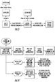
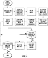
- Numerous alternatives are commercially available. Non-limiting examples of one combination of components is shown in Figures 3 to 5 , where "Microcontroller" is Parallax Propeller, the Stepper Motor Driver is Sparkfun EasyDriver, the LED Driver is a Luxeon Single LED Driver, the USB to Serial is a Parallax USB to Serial converter, and the DLP System is a Texas Instruments LightCrafter system.
- the present invention provides a method of forming a three-dimensional object, comprising the steps of: (a) providing a carrier and a build plate, said build plate comprising a semipermeable member, said semipermeable member comprising a build surface and a feed surface separate from said build surface, with said build surface and said carrier defining a build region therebetween, and with said feed surface in fluid contact with a polymerization inhibitor; then (concurrently and/or sequentially) (b) filing said build region with a polymerizable liquid, said polymerizable liquid contacting said build segment, (c) irradiating said build region through said build plate to produce a solid polymerized region in said build region, with a liquid film release layer comprised of said polymerizable liquid formed between said solid polymerized region and said build surface, the polymerization of which liquid film is inhibited by said polymerization inhibitor; and (d) advancing said carrier with said polymerized region adhered thereto away from said build surface on said stationary build plate to create
- the method includes (e) continuing and/or repeating steps (b) through (d) to produce a subsequent polymerized region adhered to a previous polymerized region until the continued or repeated deposition of polymerized regions adhered to one another forms said three-dimensional object.
- the method can be carried out in a continuous fashion, though it will be appreciated that the individual steps noted above may be carried out sequentially, concurrently, or a combination thereof. Indeed, the rate of steps can be varied over time depending upon factors such as the density and/or complexity of the region under fabrication.
- the present invention in some embodiments permits elimination of this "back-up" step and allows the carrier to be advanced unidirectionally, or in a single direction, without intervening movement of the window for re-coating, or "snapping" of a pre-formed elastic release-layer.
- reciprocation is utilized not for the purpose of obtaining release, but for the purpose of more rapidly filling or pumping polymerizable liquid into the build region.
- the advancing step is carried out sequentially in uniform increments (e.g., of from 0.1 or 1 microns, up to 10 or 100 microns, or more) for each step or increment. In some embodiments, the advancing step is carried out sequentially in variable increments ( e.g., each increment ranging from 0.1 or 1 microns, up to 10 or 100 microns, or more) for each step or increment.
- the size of the increment, along with the rate of advancing, will depend in part upon factors such as temperature, pressure, structure of the article being produced ( e.g ., size, density, complexity, configuration, etc.)
- the advancing step is carried out continuously, at a uniform or variable rate.
- the rate of advance (whether carried out sequentially or continuously) is from about 0.1 1, or 10 microns per second, up to about to 100, 1,000, or 10,000 microns per second, again depending again depending on factors such as temperature, pressure, structure of the article being produced, intensity of radiation, etc
- the filling step is carried out by forcing said polymerizable liquid into said build region under pressure.
- the advancing step or steps may be carried out at a rate or cumulative or average rate of at least 0.1, 1, 10, 50, 100, 500 or 1000 microns per second, or more.
- the pressure may be whatever is sufficient to increase the rate of said advancing step(s) at least 2, 4, 6, 8 or 10 times as compared to the maximum rate of repetition of said advancing steps in the absence of said pressure.
- both the feed surface and the polymerizable liquid can be are in fluid contact with the same compressed gas (e.g., one comprising from 20 to 95 percent by volume of oxygen, the oxygen serving as the polymerization inhibitor.
- the size of the pressure vessel can be kept smaller relative to the size of the product being fabricated and higher pressures can (if desired) be more readily utilized.
- the irradiating step is in some embodiments carried out with patterned irradiation.
- the patterned irradiation may be a fixed pattern or may be a variable pattern created by a pattern generator (e.g ., a DLP) as discussed above, depending upon the particular item being fabricated.
- a pattern generator e.g ., a DLP
- each irradiating step may be any suitable time or duration depending on factors such as the intensity of the irradiation, the presence or absence of dyes in the polymerizable material, the rate of growth, etc.
- each irradiating step can be from 0.001, 0.01, 0.1, 1 or 10 microseconds, up to 1, 10, or 100 minutes, or more, in duration.
- the interval between each irradiating step is in some embodiments preferably as brief as possible, e.g ., from 0.001, 0.01, 0.1, or 1 microseconds up to 0.1, 1, or 10 seconds.
- the build surface is flat; in other the build surface is irregular such as convexly or concavely curved, or has walls or trenches formed therein. In either case the build surface may be smooth or textured.
- Curved and/or irregular build plates or build surfaces can be used in fiber or rod formation, to provide different materials to a single object being fabricated (that is, different polymerizable liquids to the same build surface through channels or trenches formed in the build surface, each associated with a separate liquid supply, etc.
- Carrier Feed Channels for Polymerizable liquid While polymerizable liquid may be provided directly to the build plate from a liquid conduit and reservoir system, in some embodiments the carrier include one or more feed channels therein.
- the carrier feed channels are in fluid communication with the polymerizable liquid supply, for example a reservoir and associated pump. Different carrier feed channels may be in fluid communication with the same supply and operate simultaneously with one another, or different carrier feed channels may be separately controllable from one another (for example, through the provision of a pump and/or valve for each). Separately controllable feed channels may be in fluid communication with a reservoir containing the same polymerizable liquid, or may be in fluid communication with a reservoir containing different polymerizable liquids. Through the use of valve assemblies, different polymerizable liquids may in some embodiments be alternately fed through the same feed channel, if desired.
- the carrier is vertically reciprocated with respect to the build surface to enhance or speed the refilling of the build region with the polymerizable liquid.
- the vertically reciprocating step which comprises an upstroke and a downstroke, is carried out with the distance of travel of the upstroke being greater than the distance of travel of the downstroke, to thereby concurrently carry out the advancing step (that is, driving the carrier away from the build plate in the Z dimension) in part or in whole.
- the speed of the upstroke gradually accelerates (that is, there is provided a gradual start and/or gradual acceleration of the upstroke, over a period of at least 20, 30, 40, or 50 percent of the total time of the upstroke, until the conclusion of the upstroke, or the change of direction which represents the beginning of the downstroke. Stated differently, the upstroke begins, or starts, gently or gradually.
- the speed of the downstroke gradually decelerates (that is, there is provided a gradual termination and/or gradual deceleration of the downstroke, over a period of at least 20, 30, 40, or 50 percent of the total time of the downstroke. Stated differently, the downstroke concludes, or ends, gently or gradually.
- each reciprocating step may be consist of a single upstroke and downstroke, the reciprocation step may comprise a plurality of 2, 3, 4 or 5 or more linked set of reciprocations, which may e the same or different in frequent and/or amplitude
- the vertically reciprocating step is carried out over a total time of from 0.01 or 0.1 seconds up to 1 or 10 seconds ( e.g., per cycle of an upstroke and a downstroke).
- the upstroke distance of travel is from 0.02 or 0.2 millimeters (or 20 or 200 microns) to 1 or 10 millimeters (or 1000 to 10,000 microns).
- the distance of travel of the downstroke may be the same as, or less than, the distance of travel of the upstroke, where a lesser distance of travel for the downstroke serves to achieve the advancing of the carrier away from the build surface as the three-dimensional object is gradually formed.
- a reciprocation step comprises multiple linked reciprocations
- the sum distance of travel of all upstrokes in that set is preferably greater than the sum distance of travel of all downstrokes in that set, to achieve the advancing of the carrier away from the build surface as the three-dimensional object is gradually formed.
- the vertically reciprocating step does not cause the formation of gas bubbles or a gas pocket in the build region, but instead the build region remains filled with the polymerizable liquid throughout the reciprocation steps, and the gradient of polymerization zone or region remains in contact with the "dead zone" and with the growing object being fabricated throughout the reciprocation steps.
- a purpose of the reciprocation is to speed or enhance the refilling of the build region, particularly where larger build regions are to be refilled with polymerizable liquid, as compared to the speed at which the build region could be refilled without the reciprocation step.
- the advancing step is carried out intermittently at a rate of 1, 2, 5 or 10 individual advances per minute up to 300, 600, or 1000 individual advances per minute, each followed by a pause during which an irradiating step is carried out.
- one or more reciprocation steps e.g ., upstroke plus downstroke
- the reciprocating steps may be nested within the advancing steps.
- the individual advances are carried out over an average distance of travel for each advance of from 10 or 50 microns to 100 or 200 microns (optionally including the total distance of travel for each vertically reciprocating step, e.g., the sum of the upstroke distance minus the downstroke distance).
- Apparatus for carrying out the invention in which the reciprocation steps described herein are implemented substantially as described above, with the drive associated with the carrier, and/or with an additional drive operatively associated with the transparent member, and with the controller operatively associated with either or both thereof and configured to reciprocate the carrier and transparent member with respect to one another as described above.
- the light is concentrated or "focused" at the build region to increase the speed of fabrication. This may be accomplished using an optical device such as an objective lens.
- the speed of fabrication may be generally proportional to the light intensity.
- the build speed in millimeters per hour may be calculated by multiplying the light intensity in milliWatts per square centimeter and a multiplier.
- the multiplier may depend on a variety of factors, including those discussed below.
- a range of multipliers, from low to high, may be employed. On the low end of the range, the multiplier may be about 10, 15, 20 or 30. On the high end of the multiplier range, the multiplier may be about 150, 300, 400 or more.
- a band pass filter may be used with a mercury bulb light source to provide 365 ⁇ 10 nm light measured at Full Width Half Maximum (FWHM).
- a band pass filter may be used with an LED light source to provide 375 ⁇ 15 nm light measured at FWHM.
- poymerizable liquids used in such processes are, in general, free radical polymerizable liquids with oxygen as the inhibitor, or acid-catalyzed or cationically polymerizable liquids with a base as the inhibitor.
- Some specific polymerizable liquids will of course cure more rapidly or efficiently than others and hence be more amenable to higher speeds, though this may be offset at least in part by further increasing light intensity.
- the "dead zone” may become thinner as inhibitor is consumed. If the dead zone is lost then the process will be disrupted.
- the supply of inhibitor may be enhanced by any suitable means, including providing an enriched and/or pressurized atmosphere of inhibitor, a more porous semipermeable member, a stronger or more powerful inhibitor (particularly where a base is employed), etc.
- lower viscosity polymerizable liquids are more amenable to higher speeds, particularly for fabrication of articles with a large and/or dense cross section (although this can be offset at least in part by increasing light intensity).
- the viscosity of the polymerizable liquid can advantageously be reduced by heating the polymerizable liquid, as described above.
- speed of fabrication can be enhanced by introducing reciprocation to "pump" the polymerizable liquid, as described above, and/or the use of feeding the polymerizable liquid through the carrier, as also described above, and/or heating and/or pressurizing the polymerizable liquid, as also described above.
- Each light engine may be configured to project an image (e.g., an array of pixels) into the build region such that a plurality of "tiled" images are projected into the build region.
- the term "light engine” can mean an assembly including a light source, a DLP device such as a digital micromirror device and an optical device such as an objective lens.
- the "light engine” may also include electronics such as a controller that is operatively associated with one or more of the other components.
- FIGS 17A-17C This is shown schematically in Figures 17A-17C .
- the light engine assemblies 130A, 130B produce adjacent or "tiled" images 140A, 140B.
- the images are slightly misaligned; that is, there is a gap between them.
- the images are aligned; there is no gap and no overlap between them.
- the configuration with the overlapped images shown in Figure 17C is employed with some form of "blending" or “smoothing" of the overlapped regions as generally discussed in, for example, U.S. Patent Nos. 7,292,207 , 8,102,332 , 8,427,391 , 8,446,431 and U.S. Patent Application Publication Nos. 2013/0269882 , 2013/0278840 and 2013/0321475 , the disclosures of which are incorporated herein in their entireties.
- the tiled images can allow for larger build areas without sacrificing light intensity, and therefore can facilitate faster build speeds for larger objects. It will be understood that more than two light engine assemblies (and corresponding tiled images) may be employed.
- Various embodiments of the invention employ at least 4, 8, 16, 32, 64, 128 or more tiled images.
- Three-dimensional products produced by the methods and processes of the present invention may be final, finished or substantially finished products, or may be intermediate products subject to further manufacturing steps such as surface treatment, laser cutting, electric discharge machining, etc., is intended.
- Intermediate products include products for which further additive manufacturing, in the same or a different apparatus, may be carried out).
- a fault or cleavage line may be introduced deliberately into an ongoing "build” by disrupting, and then reinstating, the gradient of polymerization zone, to terminate one region of the finished product, or simply because a particular region of the finished product or "build" is less fragile than others.
- Numerous different products can be made by the methods and apparatus of the present invention, including both large-scale models or prototypes, small custom products, miniature or microminiature products or devices, etc.
- Examples include, but are not limited to, medical devices and implantable medical devices such as stents, drug delivery depots, functional structures, microneedle arrays, fibers and rods such as waveguides, micromechanical devices, microfluidic devices, etc.
- the product can have a height of from 0.1 or 1 millimeters up to 10 or 100 millimeters, or more, and/or a maximum width of from 0.1 or 1 millimeters up to 10 or 100 millimeters, or more.
- the product can have a height of from 10 or 100 nanometers up to 10 or 100 microns, or more, and/or a maximum width of from 10 or 100 nanometers up to 10 or 100 microns, or more.
- the ratio of height to width of the product is at least 2:1, 10:1, 50:1, or 100:1, or more, or a width to height ratio of 1:1, 10:1, 50:1, or 100:1, or more.
- the product has at least one, or a plurality of, pores or channels formed therein, as discussed further below.
- the processes described herein can produce products with a variety of different properties.
- the products are rigid; in other embodiments the products are flexible or resilient.
- the products are a solid; in other embodiments, the products are a gel such as a hydrogel.
- the products have a shape memory (that is, return substantially to a previous shape after being deformed, so long as they are not deformed to the point of structural failure).
- the products are unitary (that is, formed of a single polymerizable liquid); in some embodiments, the products are composites (that is, formed of two or more different polymerizable liquids). Particular properties will be determined by factors such as the choice of polymerizable liquid(s) employed.
- the product or article made has at least one overhanging feature (or "overhang”), such as a bridging element between two supporting bodies, or a cantilevered element projecting from one substantially vertical support body.
- overhang such as a bridging element between two supporting bodies, or a cantilevered element projecting from one substantially vertical support body.
- the present invention is concerned with the production of three-dimensional objects that include a hollow portion, or a portion of which is hollow.
- objects generally comprise a wall and an internal cavity or chamber.
- the wall is generally continuous, giving the object a continuous or "solid” rather than perforated appearance.
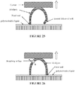
- the production of such objects by the methods described herein is facilitated by forming at least one breathing orifice in the wall, generally in the upper portion (that is, the portion produced first, as compared to the lower portion), and in some embodiments adjacent the carrier.
- the filling step is carried out by providing a liquid pool of polymerizable liquid on the build surface.
- that liquid pool creates a fluid seal that seals the internal cavity to the build surface during the advancing step or steps while the three dimensional object is being produced.
- the breathing orifice(s) thus constitute the only fluid communication between the internal cavity.
- the internal cavity has a volume of at least 1 or 2, or 10 or 20, cubic centimeters.
- the wall may be of any suitable thickness, and may be uniform or non-uniform in thickness. If non-uniform in thickness, the wall may have a thin region, relative to other thicker region, that is susceptible to failure: for example, a region (which may be in the lower wall portion) with a maximum thickness of not more than 2 or 4 millimeters, or-in the case of larger objects (e.g ., objects with an internal cavity volume of 2 or 4 liters or more)-1 or 2 centimeters.
- the internal cavity may be closed by the polymerizable material during later phases of production thereof, before the object is separated from the build surface, or the internal cavity may be open to the exterior of the object once the object is separated from the build surface. In either case, the cavity is generally sealed to the build surface during production of the object by the liquid polymerizable material positioned on top of the build surface.
- the volume of the internal cavity is at least 50, 60, 70 or 80 percent, up to 95 or 99 percent, of the total volume of the object (the sum of the volume of the cavity plus the total volume occupied by the object wall).
- the object is an open object once separated from the build surface as noted above, such volumes are calculated after completion of the object, just prior to separation and removal from the build surface or the carrier (whichever closes the open portion of the completed object based on the orientation of the object for production, and of course not including the volume of the carrier and/or build surface itself in the calculation of the volume of the object).
- the volume of the internal cavity may represent only a portion of the total volume of the object, this internal cavity nonetheless can benefit from the addition of breathing vents to facilitate accurate replication of the object without the burden of unduly large negative pressures.
- the internal cavity may be completely hollow, or may contain structural support or rigidifying elements, depending on the material from which the object is made and the purpose for which the object is intended
- the breathing orifice may comprise a simple port (as shown in Figures 26-27 discussed below) with any suitable regular or irregular cross-section.
- the breathing orifice may comprises a labyrinthine port: that is, a port following a path containing curves, corners, and composites thereof, preferably constricted in cross-section, to which a liquid sealant may more readily adhere and more securely seal when solidified.
- the completed object has an open base which can be oriented for production first ( e.g., as the upper portion) the open base may serve as a breathing orifice for the object so long as it is aligned with one or more corresponding breathing orifices formed in the carrier, as discussed below.
- the breathing orifice(s) may optionally be sealed. Sealing may be done with any suitable material, including but not limited to thermoplastic fillers, and liquid adhesive (e.g., epoxy, urethane, cyanoacrylate, etc.) Alternatively, and depending upon the particular object being produced, the lower portion (representing the end or near-end product) may be separated from the upper portion (which represents an intermediate portion discarded during manufacturing), or at least that segment of the upper portion which contains the orifice(s). Such separating may be achieved by any suitable technique, including but not limited to cutting, burning, grinding, and combinations thereof.
- the provision of one or more breathing orifices advantageously reduces vacuum forces on the window, allows for faster and higher light intensity production (e.g., in continuous rather than intermittent or reciprocal mode) without undue damage to the object and/or build surface; allows for larger total surface area of objects adjacent the build surface; reduces flow limitations on the polymerizable liquid by allowing liquid inside the object to contribute to production of the wall; and/or supports higher part fidelity, all depending upon the geometry and performance requirements for the particular object being produced and the characteristics of the particular polymerizable liquid from which that object is being produced.
- the methods may be carried out with a method and apparatus as described in Hull, US Patent No. 5,236,637 , at Figure 4 , where the polymerizable liquid is floated on top of an immiscible liquid layer (said to be "non-wetting" therein).
- the immiscible liquid layer serves as the build surface.
- the immiscible liquid (which may be aqueous or non-aqueous) preferably: (i) has a density greater than the polymerizable liquid, (ii) is immiscible with the polymerizable liquid, and (iii) is wettable with the polymerizable liquid.
- Ingredients such as surfactants, wetting agents, viscosity-enhancing agents, pigments, and particles may optionally be included in either or both of the polymerizable liquid or immiscible liquid.
- Figure 6 is a top view and Figure 7 is an exploded view of a 7.62 centimeter (3 inch) by 40.64 centimeter (16 inch) "high aspect" rectangular build plate (or “window") assembly of the present invention, where the film dimensions are 8.89 centimeters (3.5 inches) by 43.18 centimeters (17 inches).
- the greater size of the film itself as compared to the internal diameter of vat ring and film base provides a peripheral or circumferential flange portion in the film that is clamped between the vat ring and the film base, as shown in side-sectional view in Figure 8 .
- One or more registration holes may be provided in the polymer film in the peripheral or circumferential flange portion to aid in aligning the polymer film between the vat ring and film base, which are fastened to one another with a plurality of screws (not shown) extending from one to the other (some or all passing through holes in the peripheral edge of the polymer film) in a manner that rigidly and securely clamps the polymer film therebetween.
- a tension ring is provided that abuts the polymer film and stretches the film to rigidity the film.
- the tension ring may be provided as a pre-set member, or may be an adjustable member. Adjustment may be achieved by providing a spring plate facing the tension ring, with one or more compressible elements such as polymer cushions or springs (e.g., flat springs, coil springs, wave springs etc.) therebetween, and with adjustable fasteners such as screw fasteners or the like passing from the spring plate through (or around) the tension ring to the film base.
- Polymer films are preferably fluoropolymer films, such as an amorphous thermoplastic fluoropolymer, in a thickness of 0.01 or 0.05 millimeters to 0.1 or 1 millimeters, or more.
- fluoropolymer films such as an amorphous thermoplastic fluoropolymer, in a thickness of 0.01 or 0.05 millimeters to 0.1 or 1 millimeters, or more.
- Biogeneral Teflon AF 2400 polymer film which is 0.0035 inches (0.09 millimeters) thick
- Random Technologies Teflon AF 2400 polymer film which is 0.004 inches (0.1 millimeters) thick.
- Tension on the film is preferably adjusted with the tension ring to about 10 to 100 pounds, depending on operating conditions such as fabrication speed.
- the vat ring, film base, tension ring, and tension ring spring plate may be fabricated of any suitable, preferably rigid, material, including metals (e.g ., stainless steel, aluminum and aluminum alloys), carbon fiber, polymers, and composites thereof.
- metals e.g ., stainless steel, aluminum and aluminum alloys
- carbon fiber e.g ., carbon fiber, polymers, and composites thereof.
- Registration posts and corresponding sockets may be provided in any of the vat ring, film base, tension ring and/or spring plate, as desired.
- Figure 9 is a top view and Figure 10 is an exploded view of a 7.32 centimeter (2.88 inch) diameter round build plate of the invention, where the film dimension may be 10.16 centimeters (4 inches) in diameter. Construction is in like manner to that given in Example 1 above, with a circumferential wave spring assembly shown in place. Tension on the film preferably adjusted to a like tension as given in Example 1 above (again depending on other operating conditions such as fabrication speed).
- Figure 10 is an exploded view of the build plate of Figure 8 .
- Figure 11 shows various alternate embodiments of the build plates of Figures 7-10 . Materials and tensions may be in like manner as described above.
- Figure 12 is a front perspective view
- Figure 13 is a side view
- Figure 14 is a rear perspective view of an apparatus 100 according to an exemplary embodiment of the invention.
- the apparatus 100 includes a frame 102 and an enclosure 104. Much of the enclosure 104 is removed or shown transparent in Figures 12-14 .
- the apparatus 100 includes several of the same or similar components and features as the apparatus described above in reference to Figure 2 .
- a build chamber 106 is provided on a base plate 108 that is connected to the frame 102.
- the build chamber 106 is defined by a wall or vat ring 110 and a build plate or "window" such as one of the windows described above in reference to Figures 2 and 6 -11.
- a carrier 112 is driven in a vertical direction along a rail 114 by a motor 116.
- the motor may be any suitable type of motor, such as a servo motor.
- An exemplary suitable motor is the NXM45A motor available from Oriental Motor of Tokyo, Japan.
- a liquid reservoir 118 is in fluid communication with the build chamber 106 to replenish the build chamber 106 with liquid resin.
- tubing may run from the liquid reservoir 118 to the build chamber 106.
- a valve 120 controls the flow of liquid resin from the liquid reservoir 118 to the build chamber 106.
- An exemplary suitable valve is a pinch-style aluminum solenoid valve for tubing available from McMaster-Carr of Atlanta, Georgia.
- the frame 102 includes rails 122 or other some other mounting feature on which a light engine assembly 130 ( Figure 15 ) is held or mounted.
- a light source 124 is coupled to the light engine assembly 130 using a light guide entrance cable 126.
- the light source 124 may be any suitable light source such as a BlueWave® 200 system available from Dymax Corporation of Torrington, Connecticut.
- the light engine or light engine assembly 130 includes condenser lens assembly 132 and a digital light processing (DLP) system including a digital micromirror device (DMD) 134 and an optical or projection lens assembly 136 (which may include an objective lens).
- DLP digital light processing
- DMD digital micromirror device
- optical or projection lens assembly 136 which may include an objective lens.
- a suitable DLP system is the DLP DiscoveryTM 4100 system available from Texas Instruments, Inc. of Dallas, Texas. Light from the DLP system is reflected off a mirror 138 and illuminates the build chamber 106. Specifically, an "image" 140 is projected at the build surface or window.
- an electronic component plate or breadboard 150 is connected to the frame 102.
- a plurality of electrical or electronic components are mounted on the breadboard 150.
- a controller or processor 152 is operatively associated with various components such as the motor 116, the valve 120, the light source 124 and the light engine assembly 130 described above.
- a suitable controller is the Propeller Proto Board available from Parallax, Inc. of Rocklin, California.
- controller 152 Other electrical or electronic components operatively associated with the controller 152 include a power supply 154 and a motor driver 158 for controlling the motor 116.
- a motor driver 158 for controlling the motor 116.
- an LED light source controlled by pulse width modulation (PWM) driver 156 is used instead of a mercury lamp (e.g., the Dymax light source described above).
- PWM pulse width modulation
- a suitable power supply is a 24 Volt, 2.5A, 60W, switching power supply (e.g., part number PS1-60W-24 (HF60W-SL-24) available from Marlin P. Jones & Assoc, Inc. of Lake Park, Florida).
- a suitable LED driver is a 24 Volt, 1.4A LED driver (e.g., part number 788-1041-ND available from Digi-Key of Thief River Falls, Minnesota).
- a suitable motor driver is the NXD20-A motor driver available from Oriental Motor of Tokyo, Japan.
- the apparatus of Figures 12-15 has been used to produce an "image size" of about 75 mm by 100 mm with light intensity of about 5 mW/cm 2 .
- the apparatus of Figures 12-15 has been used to build objects at speeds of about 100 to 500 mm/hr. The build speed is dependent on light intensity and the geometry of the object.
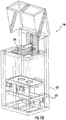
- Figure 16 is a front perspective view of an apparatus 200 according to another exemplary embodiment of the invention.
- the apparatus 200 includes the same components and features of the apparatus 100 with the following differences.
- the apparatus 200 includes a frame 202 including rails 222 or other mounting feature at which two of the light engine assemblies 130 shown in Figure 15 may be mounted in a side-by-side relationship.
- the light engine assemblies 130 are configured to provide a pair of "tiled" images at the build station 206. The use of multiple light engines to provide tiled images is described in more detail above.
- the apparatus of Figure 16 has been used to provide a tiled "image size" of about 150 mm by 200 mm with light intensity of about 1 mW/cm 2 .
- the apparatus of Figure 16 has been used to build objects at speeds of about 50 to 100 mm/hr. The build speed is dependent on light intensity and the geometry of the object.
- Figure 18 is a front perspective view and Figure 19 is a side view of an apparatus 300 according to another exemplary embodiment of the invention.
- the apparatus 300 includes the same components and features of the apparatus 100 with the following differences.
- the apparatus 300 includes a frame 302 including rails 322 or other mounting feature at which a light engine assembly 330 shown in Figure 20 may be mounted in a different orientation than the light assembly 130 of the apparatus 100.
- the light engine assembly 330 includes a condenser lens assembly 332 and a digital light processing (DLP) system including a digital micromirror device (DMD) 334 and an optical or projection lens assembly 336 (which may include an objective lens).
- DLP digital light processing
- DMD digital micromirror device
- a suitable DLP system is the DLP DiscoveryTM 4100 system available from Texas Instruments, Inc. of Dallas, Texas.
- Light from the DLP system illuminates the build chamber 306. Specifically, an "image" 340 is projected at the build surface or window. In contrast to the apparatus 100, a reflective mirror is not used with the apparatus 300.
- the apparatus of Figures 18-20 has been used to provide "image sizes" of about 10.5 mm by 14 mm and about 24 mm by 32 mm with light intensity of about 200 mW/cm 2 and 40 mW/cm 2
- the apparatus of Figures 18-20 has been used to build objects at speeds of about 10,000 and 4,000 mm/hr. The build speed is dependent on light intensity and the geometry of the object.
- This Example illustrates the control of a method and apparatus of the invention with an example program written utilizing Lua scripting.
- Program code corresponding to such instructions, or variations thereof that will be apparent to those skilled in the art, is written in accordance with known techniques based upon the particular microcontroller used.
- a part consists of slices of polymer which are printed continuously.
- the shape of each slice is defined by the frame that is being displayed by the light engine.
- the frame represents the final output for a slice.
- the frame is what manifests as the physical geometry of the part.
- the data in the frame is what is projected by the printer to cure the polymer.
- Slice All the 2D geometry that will be outputted to a frame should be combined in a Slice.
- Slices can consist of procedural geometry, Slices of a 3D model or any combination of the two. The slice generating process allows the user to have direct control over the composition of any frame.
- a slice is a special type of 2D geometry derived from a 3D model of a part. It represents the geometry that intersects a plane that is parallel to the window. Parts are usually constructed by taking 3D models and slicing them at very small intervals. Each slice is then interpreted in succession by the printer and used to cure the polymer at the proper height.
- Procedural Geometry Procedurally generated geometry can also be added to a slice. This is accomplished by invoking shape generation functions, such as “addcircle”, “addrectangle”, and others. Each function allows projection of the corresponding shape onto the printing window. A produced part appears as a vertically extruded shape or combination of shapes.
- Coordinate spaces Stage.
- the coordinate system that the stage uses is usually calibrated such that the origin is 1-20 microns above the window.
- Coordinate spaces Slice. Coordinate system of the projected slice is such that origin is located at the center of the print window.
- Printing a sliced model consists of 4 main parts: Loading the data, preparing the printer, printing, and shutdown.
- the first step of the printing process is to calibrate the system and set the stage to its starting position by calling gotostart.
- the first line of the for loop uses the infoline command to display the current slice index in the sidebar.
- gotostart The main purpose of gotostart is to calibrate the stage. This function resets the coordinate system to have the origin at the lowest point, where the limit switch is activated. Calling this command will move the stage down until the limit switch in the printer is activated; this should occur when the stage is at the absolute minimum height.
- gotostart() moves stage to start at the maximum speed which varies from printer to printer.
- gotostart() --moving to origin at default speed gotostart(number speed) moves stage to start at speed given in millimeters/hour. gotostart(15000)--moving stage to origin at 15000mm/hr
- moveto allows the user to direct the stage to a desired height at a given speed. Safe upper and lower limits to speed and acceleration are ensured internally. moveto(number targetHeight, number speed )
- This version of the function allows an acceleration to be defined as well as speed. The stage starts moving at initial speed and then increases by acceleration.
- moveto (number targetHeight, number speed, table controlPoints, function callback ) This function behaves similar to the basic version of the function. It starts at its initial speed and position and moves to the highest point on the control point table. callback is called when the stage passes each control point.
- moveto (number targetHeight, number speed, number acceleration, table controlPoints, function callback ) This function is the same as above except the user can pass an acceleration.
- the stage accelerates from its initial position continuously until it reaches the last control point.
- moveby allows the user to change the height of the stage by a desired amount at a given speed. Safe upper and lower limits to speed and acceleration are ensured internally. moveby(number dHeight, number initalSpeed ) 1 moveby(-2, 15000) --moving down 2mm at 15,000mm/hr
- relay is used to turn the light engine on or off in the printer.
- the light engine must be on in order to print. Make sure the relay is set to off at the end of the script.
- addcircle(number x , number y , number radius, number slicelndex) addcircle draws a circle in the specified slice slice.
- addrectangle(number x , number y , number width, number height number slicelndex) addrectangle draws a rectangle in the specified slice.
- addline (number x0, number y0, number x1, number y1, number slicelndex) addline draws a line segment.
- text(number x , number y , number scale, string text, number sliceIndex ) addtext draws text on the specified slice starting at position 'x, y' with letters of size 'scale'.
- fillmask (number color, number sliceIndex, number figureIndex ) fillmask is used to control how the procedural geometry is drawn. fillmask tells the figure in question to fill the entirety of its interior with color.
- -color can be any number on the range 0 to 255. Where 0 is black and 255 is white, any value in between is a shade of grey interpolated linearly between black and white based on the color value. Any value less than 0 will produce a transparent color.
- myCircle addCircle(0,0,5,0)-- creating the circle to fill fillmask(255, 0, myCircle)- -Creating a white filled circle
- linemask (number color, number sliceIndex, number figureIndex ) linemask is used to control how the procedural geometry is drawn. linemask tells a figure to draw its outline in a specific color. The width of the outline is defined by the function linewidth.
- myCircle addCircle(0,0,20,0)-- creating the circle to fill linemask(255, 0, myCircle)- -setting the outline of the circle to be white fillmask(150,0, myCircle)- -setting the fill of the circle to be grey
- linewidth(number width, number sliceIndex, number figureIndex ) linewidth is used to set the width of the line that linemask will use to outline the figure.
- loadmask(string filepath ) loadmask allows for advanced fill control. It enables the user to load a texture from a bitmap file and use it to fill the entirety of a figure with the texture.
- texture loadmask("voronoi_noise.png") -loading texture.
- voronoi_noise.png is in the same directory as the script.
- myCircle addCircle(0,0,20,0)- -creating the circle to fill fillmask(texture, 0, myCircle)- -filling the circle with voronoi noise
- showframe(number slicelndex) showframe is essential to the printing process. This function sends the data from a slice to the printer. Call showframes on a frame that doesn't exist to render a black frame e.g. showframe(-1).
- framegradient(number slope ) framegradient is designed to compensate for differences in light intensity.
- calcframe is designed to analyze the construction of a slice calculates the last frame shown.
- loadframe is used to load a single slice from a supported bitmap file.
- addslice(number sliceHeight) addslice creates a new slice at a given height at the end of the slice stack. addslice(.05) --adding a slice at .05mm
- addslice creates a new slice at a given height and slice index.
- loadslices(string filepath) loadslices is used to load all the slices from a 2D slice file.
- sliceheight(number slicelndex) sliceheight is used to find the height of a slice in mm off the base.
- sleep(number seconds) sleep allows the user to pause the execution of the program for a set number of seconds.
- clock returns the current time in seconds. It is accurate at least up to the millisecond and should therefore be used instead of Lua's built in clock functionality. clock should be used as a means to measure differences in time as the start time for the second count varies from system to system.
- set of functions can be used with printer models that support fluid control. Before the script finishes executing, setlevels(0,0) should be called to ensure that the pump stops pumping fluid into the vat.
- setlevels(number min, number max) setlevels allows the user to define how much fluid should be in the vat.
- the fluid height will be automatically regulated by a pump.
- the difference between min and max should be greater than 0.05 to ensure that the valve is not constantly opening and closing.
- infoline(int lineIndex, string text ) infoline allows the user to display up to 5 lines of text in a constant position on the sidebar of the Programmable Printer Platform. This function is often used to allow the user to monitor several changing variables at once.
- infoline (1, string.format("Vat is %d percent full.”, getcurrentlevel()*100) )
- the math standard library contains several different functions that are useful in calculating geometry.
- the string object is most useful in printing for manipulating info strings. For details contact LabLua at Departamento de Informática, PUC-Rio, Rua Marquês de S ⁇ o Vicente, 225; 22451-900 Rio de Janeiro, RJ, Brazil
- This example shows a Lua script program corresponding to Example 7 above for continuous three dimension printing.
- This example shows a Lua script program for two fitted parts that use procedural geometry.
- FIG. 21 A process of the present invention is illustrated in Figure 21 , where the vertical axis illustrates the movement of the carrier away from the build surface.
- the vertical movement or advancing step (which can be achieved by driving either the carrier or the build surface, preferably the carrier), is continuous and unidirectional, and the irradiating step is carried out continuously.
- Polymerization of the article being fabricated occurs from a gradient of polymerization, and hence creation of "layer by layer" fault lines within the article is minimized.
- FIG. 22 An alternate embodiment of the present invention is illustrated in Figure 22 .
- the advancing step is carried out in a step-by-step manner, with pauses introduced between active advancing of the carrier and build surface away from one another.
- the irradiating step is carried out intermittently, in this case during the pauses in the advancing step.
- the inhibitor of polymerization is supplied to the dead zone in an amount sufficient to maintain the dead zone and the adjacent gradient of polymerization during the pauses in irradiation and/or advancing, the gradient of polymerization is maintained, and the formation of layers within the article of manufacture is minimized or avoided. Stated differently, the polymerization is continuous, even though the irradiating and advancing steps are not.
- Sufficient inhibitor can be supplied by any of a variety of techniques, including but not limited to: utilizing a transparent member that is sufficiently permeable to the inhibitor, enriching the inhibitor (e.g ., feeding the inhibitor from an inhibitor-enriched and/or pressurized atmosphere), etc.
- enriching the inhibitor e.g ., feeding the inhibitor from an inhibitor-enriched and/or pressurized atmosphere
- the more rapid the fabrication of the three-dimensional object that is, the more rapid the cumulative rate of advancing
- the more inhibitor will be required to maintain the dead zone and the adjacent gradient of polymerization.
- FIG. 23 A still further embodiment of the present invention is illustrated in Figure 23 .
- the advancing step is carried out in a step-by-step manner, with pauses introduced between active advancing of the carrier and build surface away from one another.
- the irradiating step is carried out intermittently, again during the pauses in the advancing step.
- the ability to maintain the dead zone and gradient of polymerization during the pauses in advancing and irradiating is taken advantage of by introducing a vertical reciprocation during the pauses in irradiation.
- Reciprocation in the vertical or Z axis can be carried out at any suitable speed in both directions (and the speed need not be the same in both directions), although it is preferred that the speed when reciprocating away is insufficient to cause the formation of gas bubbles in the build region.
- Example 10 As in Example 10 above, as long as the inhibitor of polymerization is supplied to the dead zone in an amount sufficient to maintain the dead zone and the adjacent gradient of polymerization during the reciprocation, the gradient of polymerization is maintained, the formation of layers within the article of manufacture is minimized or avoided, and the polymerization/fabrication remains continuous, even though the irradiating and advancing steps are not.
- Three dimensional objects with large solid cross sections can be difficult to print quickly due to forces required to pull resin into the build zone.
- Objects with large cross sections that are hollow have the potential to be easier to build.
- these objects face similar difficulties to solid parts when being built. This includes failure modes such as the build surface, being pulled upward and snapping back down, and/or failure of the object wall (e.g., inward collapse), as shown in Figure 25 .
- Figure 25 shows failure of the object wall late in the production of the three dimensional object, failure may also occur early in the production of the three-dimensional object, as illustrated further below.
- FIG. 26 formation of one or more breathing orifice near the carrier of an object being produced allows flow of fluid and/or gas from the hollow interior of the cavity to the exterior (dashed arrow). Such openings can assist in preservation of part integrity, speed of production, and/or high part fidelity.
- a perspective view of such an object is given in Figure 27 .
- the breathing orifice can provide direct access to the ambient atmosphere (e.g., air) as shown in Figure 26 , or can be aligned with a corresponding breathing orifice in the carrier as shown in Figure 28A (or combinations thereof).
- the finished object has an open base which can be oriented adjacent the carrier during fabrication, the open base can itself serve as the breathing orifice for the object when it is aligned with one or more breathing orifices in the carrier, as shown in Figure 28B .
- An example of such a carrier is given in Figure 29 .
- the pair of cannula parts shown in Figure 30A are examples of a tubular object with a hollow cavity. Orienting the part so that the large, flat, open, cross-section at the bottom of the part is flush with and adjacent to the carrier allows that opening to serve as the breathing orifice in the object, where a carrier having corresponding breathing openings such as shown in Figure 29 is used. In this case, note that printing in a different orientation may avoid the otherwise damaging vacuum effect, but would come at the cost of the part being prone to warping and being heavily supported, which extends the pre- and post-processing work. In order to print the cannula without modifying the part itself, the carrier shown in Figure 29 , with breathing orifices formed therein, is used.
- Figure 30A the part on the left was printed on a standard carrier without breathing orifices, and the part on the right was printed on a carrier having breathing orificies as shown in Figure 29 .
- the close-up provided in Figure 30B shows unwanted air passageways being forced into the part on the left, but not into the part on the right.
- the close-up in Figure 30C clearly shows the unwanted air passageways forced into the hollow part.
- any suitable liquid pressure regulator may be used, with the specific liquid pressure being set in accordance with the geometry of the particular three-dimensional object being produced, optionally adjustable in response to the ambient pressure.
- the polymerizable liquid supply can in some embodiments be pressurized with a regulated pressure in a range from .01 atmospheres above ambient pressure to 10 atmospheres above ambient pressure, or pumped in controlled volumes in increments from 0.001ml to 100ml for a given increment of advancement of the build platform from lum to 1000um, or at controlled rates in the range of 0.001ml/minute to 1000ml/minute for a given rate of advancement of the build platform from 1 um per minute to 10000um per minute, all generally dependent on the cross section of the part to be built.
- regulation and control can be provided to substantially equilibrate the pressure external and internal to the part.
- Figure 32 provides an alternative to the apparatus shown in Figure 31 , the polymerizable liquid supply to the internal cavity is achieved by providing a siphon line or siphon tube assembly extending from a liquid pool of polymerizable liquid maintained on the build surface through to the breathing hole or holes formed in the carrier.
- a manual or automatic priming pump may be included in the siphon line to prime the line in accordance with known techniques prior to initiating polymerization and fabrication of the object.
- the siphon line preferably includes at least one flexible or extendible portion, such as a flexible (optionally coiled) polymer tube, to accommodate upward movement of the carrier away from the build surface on which the pool of polymerizable liquid is maintained.
Landscapes
- Engineering & Computer Science (AREA)
- Chemical & Material Sciences (AREA)
- Materials Engineering (AREA)
- Manufacturing & Machinery (AREA)
- Physics & Mathematics (AREA)
- Mechanical Engineering (AREA)
- Optics & Photonics (AREA)
- Health & Medical Sciences (AREA)
- Oral & Maxillofacial Surgery (AREA)
- Thermal Sciences (AREA)
Claims (24)
- Procédé de formation d'un objet tridimensionnel, ledit objet ayant une paroi et une cavité interne, ladite paroi ayant une partie supérieure et une partie inférieure, le procédé comprenant les étapes de :fourniture d'un support et d'un élément optiquement transparent ayant une surface de construction, ledit support et ladite surface de construction définissant une zone de construction entre eux ;remplissage de ladite zone de construction avec un liquide polymérisable ;irradiation continue ou intermittente de ladite zone de construction avec une lumière à travers ledit élément optiquement transparent pour former un polymère solide à partir dudit liquide polymérisable,avancement continu ou intermittent dudit support en éloignement de ladite surface de construction pour former ledit objet tridimensionnel à partir dudit polymère solide,ledit procédé comprenant en outre l'étape de formation d'un orifice de respiration dans ladite partie supérieure de paroi pendant la formation dudit objet tridimensionnel, dans lequel :
ladite étape de remplissage comprend en outre le déplacement en va-et-vient verticalement dudit support par rapport à ladite surface de construction pour améliorer ou accélérer le remplissage de ladite zone de construction avec ledit liquide polymérisable. - Procédé selon la revendication 1, dans lequel :ladite cavité interne a un volume d'au moins 1 ou 2, ou 10 ou 20 centimètres cubes ;et / ouladite paroi présente au moins une zone d'une épaisseur maximale ne dépassant pas 2 ou 4 millimètres, ou 1 ou 2 centimètres.
- Procédé selon la revendication 1 ou 2, dans lequel ladite étape de remplissage est réalisée en fournissant un bain liquide de liquide polymérisable sur ladite surface de construction, ledit bain liquide créant un joint de fluide qui scelle ladite cavité interne à ladite surface de construction pendant ledit avancement.
- Procédé selon l'une quelconque des revendications 1 à 3, dans lequel ledit orifice de respiration comprend un orifice simple ou un orifice labyrinthique.
- Procédé selon l'une quelconque des revendications 1 à 4, comprenant en outre, après la formation dudit objet tridimensionnel, l'étape de :
scellement dudit orifice de respiration. - Procédé selon l'une quelconque des revendications 1 à 4, comprenant en outre, après la formation dudit objet tridimensionnel, l'étape de :
séparation de ladite partie inférieure d'au moins ce segment de ladite partie supérieure dans lequel ledit orifice de respiration est formé. - Procédé selon l'une quelconque des revendications 1 à 6, dans lequel le volume de ladite cavité interne est d'au moins 50 ou 60 pour cent du volume total dudit objet tridimensionnel.
- Procédé selon l'une quelconque des revendications 1 à 7, dans lequel ledit orifice de respiration dans ledit objet est en communication fluidique avec un orifice de respiration formé dans ledit support.
- Procédé selon l'une quelconque des revendications 1 à 8, dans lequel ledit orifice de respiration dans ledit objet est en communication fluidique avec l'atmosphère ambiante dans laquelle ledit objet tridimensionnel est produit.
- Procédé selon la revendication 9, dans lequel ladite atmosphère ambiante est pressurisée.
- Procédé selon la revendication 8, ou la revendication 9 ou 10 dépendant de la revendication 8, dans lequel ledit orifice de respiration dans ledit support est en communication fluidique avec une alimentation en liquide polymérisable à travers un régulateur de pression liquide.
- Procédé selon l'une quelconque des revendications 1 à 8, dans lequel ladite étape de remplissage est réalisée avec un bain de liquide polymérisable, et ledit orifice de respiration dans ledit support et / ou dans ledit objet est en communication fluidique avec ledit liquide polymérisable à travers un siphon interconnectant ledit bain et ledit orifice de respiration dans ledit support.
- Procédé selon l'une quelconque des revendications précédentes, dans lequel ledit élément optiquement transparent est composé d'un polymère fluoré semi-perméable, d'un polymère rigide perméable aux gaz, d'un verre poreux ou d'une combinaison de ceux-ci.
- Procédé selon l'une quelconque des revendications précédentes, dans lequel ladite surface de construction est fixe et stationnaire en dimensions latérales (X et Y).
- Procédé selon l'une quelconque des revendications 1 à 11, dans lequel lesdites étapes de remplissage, d'irradiation et / ou d'avancement sont effectuées simultanément aux étapes de :(i) maintien continu d'une zone morte de liquide polymérisable en contact avec ladite surface de construction, et(ii) maintien continu d'un gradient de zone de polymérisation entre ladite zone morte et ledit polymère solide et en contact avec chacun de ceux-ci, ledit gradient de zone de polymérisation comprenant ledit liquide polymérisable sous forme partiellement durcie.
- Procédé selon la revendication 15, dans lequel ledit élément optiquement transparent comprend un élément semi-perméable, et ledit maintien continu d'une zone morte est réalisé en alimentant un inhibiteur de polymérisation à travers ledit élément optiquement transparent en une quantité suffisante pour maintenir ladite zone morte et ledit gradient de polymérisation.
- Procédé selon la revendication 15 ou 16, dans lequel ledit gradient de zone de polymérisation est maintenu pendant une durée d'au moins 5, 10, 20 ou 30 secondes, ou au moins 1 ou 2 minutes.
- Procédé selon l'une quelconque des revendications précédentes, dans lequel :ledit liquide polymérisable comprend un liquide polymérisable par radicaux libres et ledit inhibiteur comprend de l'oxygène ; ouledit liquide polymérisable comprend un liquide catalysé par un acide ou polymérisable par voie cationique, et ledit inhibiteur comprend une base.
- Appareil pour former un objet tridimensionnel à partir d'un liquide polymérisable, comprenant :(a) un socle ;(b) un support associé fonctionnellement audit socle sur lequel support est formé ledit objet tridimensionnel, ledit support ayant au moins un orifice de respiration formé dans celui-ci ;(c) un élément optiquement transparent présentant une surface de construction, avec ladite surface de construction et ledit support définissant une zone de construction entre eux ;(d) une alimentation en polymère liquide associée fonctionnellement à ladite surface de construction et configurée de façon à apporter le polymère liquide dans ladite zone de construction pour solidification ou polymérisation ;(e) une source de rayonnement configurée pour irradier ladite zone de construction à travers ledit élément optiquement transparent pour former un polymère solide à partir dudit liquide polymérisable ;(f) éventuellement au moins un entraînement associé fonctionnellement soit audit élément transparent soit audit support ;(g) un contrôleur associé fonctionnellement audit support, et / ou éventuellement audit au moins un entraînement, et à ladite source de rayonnement pour faire avancer ledit support en éloignement de ladite surface de construction pour former ledit objet tridimensionnel à partir dudit polymère solide, dans lequel :
ledit contrôleur est en outre configuré pour déplacer en va-et-vient verticalement ledit support par rapport à ladite surface de construction pour améliorer ou accélérer le remplissage de ladite zone de construction avec ledit liquide polymérisable. - Appareil selon la revendication 19, comprenant en outre une ligne de siphon connectée audit orifice de respiration et configurée pour interconnecter ledit orifice de respiration avec ladite alimentation en polymère liquide.
- Appareil selon la revendication 19 ou 20, comprenant en outre :une alimentation en liquide polymérisable en communication fluidique avec ledit orifice de respiration, etun régulateur de pression de liquide associé fonctionnellement audit orifice de respiration et à ladite alimentation en liquide polymérisable.
- Appareil selon l'une quelconque des revendications 19 à 21, ledit contrôleur étant en outre configuré pour former ledit objet tridimensionnel à partir dudit polymère solide tout en exécutant simultanément à ladite alimentation, audit avancement, et/ou à ladite irradiation : (i) le maintien continu d'une zone morte de liquide polymérisable en contact avec ladite surface de construction, et (ii) le maintien continu d'un gradient de zone de polymérisation entre ladite zone morte et ledit polymère solide et en contact avec chacun d'eux, ledit gradient de zone de polymérisation comprenant ledit liquide polymérisable sous forme partiellement durcie.
- Appareil selon l'une quelconque des revendications 19 à 22, dans lequel ladite surface de construction est fixe et stationnaire en dimensions latérales (X et Y).
- Appareil selon l'une quelconque des revendications 19 à 23, dans lequel ledit élément optiquement transparent comprend un élément semi-perméable.
Applications Claiming Priority (2)
| Application Number | Priority Date | Filing Date | Title |
|---|---|---|---|
| US201462098719P | 2014-12-31 | 2014-12-31 | |
| PCT/US2015/067884 WO2016109550A1 (fr) | 2014-12-31 | 2015-12-29 | Impression en trois dimensions d'objets comprenant des orifices de respiration |
Publications (2)
| Publication Number | Publication Date |
|---|---|
| EP3240671A1 EP3240671A1 (fr) | 2017-11-08 |
| EP3240671B1 true EP3240671B1 (fr) | 2020-12-16 |
Family
ID=55275170
Family Applications (1)
| Application Number | Title | Priority Date | Filing Date |
|---|---|---|---|
| EP15831114.2A Active EP3240671B1 (fr) | 2014-12-31 | 2015-12-29 | Impression en trois dimensions d'objets comprenant des orifices de respiration |
Country Status (3)
| Country | Link |
|---|---|
| US (1) | US20170355132A1 (fr) |
| EP (1) | EP3240671B1 (fr) |
| WO (1) | WO2016109550A1 (fr) |
Families Citing this family (25)
| Publication number | Priority date | Publication date | Assignee | Title |
|---|---|---|---|---|
| GB201501089D0 (en) * | 2015-01-22 | 2015-03-11 | Univ Greenwich | Stent |
| ITUB20154169A1 (it) | 2015-10-02 | 2017-04-02 | Thelyn S R L | Metodo e apparato di foto-indurimento a substrato auto-lubrificante per la formazione di oggetti tridimensionali. |
| KR102611837B1 (ko) * | 2017-04-04 | 2023-12-07 | 엔라이트 인크. | 검류계 스캐너 보정을 위한 광학 기준 생성 |
| US10688737B2 (en) | 2017-09-14 | 2020-06-23 | General Electric Company | Method for forming fiber-reinforced polymer components |
| CN108454113A (zh) * | 2017-12-05 | 2018-08-28 | 张婷婷 | 一种3d打印构件的连接结构及其制造工艺 |
| US20200276761A1 (en) * | 2018-01-12 | 2020-09-03 | University Of Florida Research Foundation, Incorporated | Multi-material microstereolithography using injection of resin |
| AU2019204143B2 (en) | 2018-06-15 | 2025-02-27 | Howmedica Osteonics Corp. | Stackable build plates for additive manufacturing powder handling |
| EP3819101A4 (fr) * | 2018-07-05 | 2022-03-30 | Mitsui Chemicals, Inc. | Dispositif de modélisation en trois dimensions, dispositif de commande et procédé de fabrication d'un objet modélisé |
| WO2020206053A1 (fr) * | 2019-04-04 | 2020-10-08 | Calt Dynamics Ltd | Procédés, systèmes et dispositifs pour la génération d'objets en trois dimensions et le durcissement de masque physique |
| US11235515B2 (en) | 2018-07-28 | 2022-02-01 | CALT Dynamics Limited | Methods, systems, and devices for three-dimensional object generation and physical mask curing |
| EP3829850A1 (fr) | 2018-07-28 | 2021-06-09 | Calt Dynamics Ltd | Procédés, systèmes et dispositifs pour la génération d'objets en trois dimensions et le durcissement de masque physique |
| US11203156B2 (en) | 2018-08-20 | 2021-12-21 | NEXA3D Inc. | Methods and systems for photo-curing photo-sensitive material for printing and other applications |
| KR20210090197A (ko) | 2018-11-09 | 2021-07-19 | 넥사3디 인코포레이티드 | 3차원 프린팅 시스템 |
| CN112368127B (zh) | 2018-12-10 | 2022-09-02 | 深圳摩方新材科技有限公司 | 投影微立体光刻技术中控制尺寸的方法 |
| US11571853B2 (en) * | 2018-12-19 | 2023-02-07 | 3D Systems, Inc. | Precision optical assembly for three dimensional printing |
| EP3934834B1 (fr) * | 2019-03-04 | 2024-04-03 | Nikon SLM Solutions AG | Dispositif de fabrication additive d'une pièce |
| IL286370B2 (en) | 2019-03-18 | 2025-02-01 | Nexa3D Inc | Method and system for additive manufacturing |
| US10967573B2 (en) | 2019-04-02 | 2021-04-06 | NEXA3D Inc. | Tank assembly and components thereof for a 3D printing system |
| EP3722074B1 (fr) * | 2019-04-09 | 2022-06-08 | DENTSPLY SIRONA Inc. | Procédé de prévention de collecte / d'aspiration de fluide dans une fabrication additive d'objets en 3d |
| US11413819B2 (en) | 2020-09-03 | 2022-08-16 | NEXA3D Inc. | Multi-material membrane for vat polymerization printer |
| EP4232262B1 (fr) | 2020-10-23 | 2025-01-08 | BMF Material Technology Inc. | Système multi-échelles pour la micro-stéréolithographie par projection |
| US12397500B2 (en) * | 2021-08-13 | 2025-08-26 | Bmf Nano Material Technology Co., Ltd | System and method of low-waste multi-material resin printing |
| US12023865B2 (en) | 2022-08-11 | 2024-07-02 | NEXA3D Inc. | Light engines for vat polymerization 3D printers |
| US12502714B2 (en) | 2022-11-17 | 2025-12-23 | Howmedica Osteonics Corp. | Additive manufacturing build removal device and system |
| CN117291038B (zh) * | 2023-10-07 | 2024-07-26 | 南京理工大学 | 一种面向激光烧结复材的仿生薄壁结构抗冲击设计方法 |
Family Cites Families (57)
| Publication number | Priority date | Publication date | Assignee | Title |
|---|---|---|---|---|
| USRE31406E (en) | 1972-06-16 | 1983-10-04 | Syntex (U.S.A.) Inc. | Oxygen permeable contact lens composition, methods and article of manufacture |
| US4337130A (en) | 1980-06-25 | 1982-06-29 | E. I. Du Pont De Nemours And Company | Photocurable polyurethane film coatings |
| US5236637A (en) | 1984-08-08 | 1993-08-17 | 3D Systems, Inc. | Method of and apparatus for production of three dimensional objects by stereolithography |
| DE3616681A1 (de) | 1986-05-16 | 1987-11-19 | Bayer Ag | 1-aralkylpyrazole |
| US5051115A (en) | 1986-05-21 | 1991-09-24 | Linde Aktiengesellschaft | Pressure swing adsorption process |
| US5141665A (en) | 1987-03-31 | 1992-08-25 | Sherman Laboratories, Inc. | Cleaning, conditioning, storing and wetting system and method for rigid gas permeable contact lenses and other contact lenses |
| US4923906A (en) | 1987-04-30 | 1990-05-08 | Ciba-Geigy Corporation | Rigid, gas-permeable polysiloxane contact lenses |
| US5070170A (en) | 1988-02-26 | 1991-12-03 | Ciba-Geigy Corporation | Wettable, rigid gas permeable, substantially non-swellable contact lens containing block copolymer polysiloxane-polyoxyalkylene backbone units, and use thereof |
| JPH01233443A (ja) | 1988-03-15 | 1989-09-19 | Fujitsu Ltd | パターン形成方法 |
| GB9008577D0 (en) | 1990-04-17 | 1990-06-13 | Pilkington Diffractive Lenses | Rigid gas permeable lenses |
| US5162469A (en) | 1991-08-05 | 1992-11-10 | Optical Research Inc. | Composition for rigid gas permeable contact lenses |
| US5296283A (en) | 1992-01-13 | 1994-03-22 | E. I. Du Pont De Nemours And Company | Protective coating for machine-readable markings |
| AU673160B2 (en) | 1992-02-28 | 1996-10-31 | Board Of Regents, The University Of Texas System | Photopolymerizable biodegradable hydrogels as tissue contacting materials and controlled-release carriers |
| US5310571A (en) | 1992-09-01 | 1994-05-10 | Allergan, Inc. | Chemical treatment to improve oxygen permeability through and protein deposition on hydrophilic (soft) and rigid gas permeable (RGP) contact lenses |
| US5836313A (en) | 1993-02-08 | 1998-11-17 | Massachusetts Institute Of Technology | Methods for making composite hydrogels for corneal prostheses |
| US5374500A (en) | 1993-04-02 | 1994-12-20 | International Business Machines Corporation | Positive photoresist composition containing photoacid generator and use thereof |
| US5691541A (en) | 1996-05-14 | 1997-11-25 | The Regents Of The University Of California | Maskless, reticle-free, lithography |
| US6312134B1 (en) | 1996-07-25 | 2001-11-06 | Anvik Corporation | Seamless, maskless lithography system using spatial light modulator |
| US6238852B1 (en) | 1999-01-04 | 2001-05-29 | Anvik Corporation | Maskless lithography system and method with doubled throughput |
| US6248509B1 (en) | 1999-07-27 | 2001-06-19 | James E. Sanford | Maskless photoresist exposure system using mems devices |
| KR100583095B1 (ko) | 2000-06-30 | 2006-05-24 | 주식회사 하이닉스반도체 | 광산 발생제와 함께 광 라디칼 발생제(prg)를 포함하는포토레지스트 조성물 |
| US6939940B2 (en) | 2000-09-13 | 2005-09-06 | The United States Of America As Represented By The Administrator Of The National Aeronautics And Space Administration | Liquid crystalline thermosets from ester, ester-imide, and ester-amide oligomers |
| US6562269B2 (en) * | 2001-01-05 | 2003-05-13 | 3D Systems, Inc. | Layer normalizing device for selective deposition modeling |
| DE10119817A1 (de) | 2001-04-23 | 2002-10-24 | Envision Technologies Gmbh | Vorrichtung und Verfahren für die zerstörungsfreie Trennung ausgehärteter Materialschichten von einer planen Bauebene |
| US6932930B2 (en) | 2003-03-10 | 2005-08-23 | Synecor, Llc | Intraluminal prostheses having polymeric material with selectively modified crystallinity and methods of making same |
| EP1694731B1 (fr) | 2003-09-23 | 2012-03-28 | University Of North Carolina At Chapel Hill | Perfluoropolyethers photopolymerisables destines a etre utilises comme nouveaux materiaux dans des dispositifs microfluidiques |
| JP4044505B2 (ja) | 2003-09-29 | 2008-02-06 | 独立行政法人科学技術振興機構 | 光酸発生剤 |
| JP2007509716A (ja) | 2003-10-29 | 2007-04-19 | ジェンティス インコーポレイテッド | 組織工学用の重合可能なエマルション |
| MXPA06006738A (es) | 2003-12-19 | 2006-08-31 | Univ North Carolina | Metodos para fabricar micro- y nano-estructuras aisladas utilizando litografia suave o de impresion. |
| CA2554160A1 (fr) | 2004-01-23 | 2005-09-22 | The University Of North Carolina At Chapel Hill | Materiaux liquides a utiliser dans des cellules electrochimiques |
| US7649029B2 (en) | 2004-05-17 | 2010-01-19 | 3M Innovative Properties Company | Dental compositions containing nanozirconia fillers |
| US7097302B2 (en) | 2004-07-03 | 2006-08-29 | Mcgregor Scott D | Rigid gas permeable contact lens with 3-part curvature |
| US7556490B2 (en) | 2004-07-30 | 2009-07-07 | Board Of Regents, The University Of Texas System | Multi-material stereolithography |
| US7292207B1 (en) | 2004-08-27 | 2007-11-06 | Sun Microsystems, Inc. | Computing blending functions for the tiling of overlapped video projectors |
| EP1784302B1 (fr) | 2004-09-01 | 2016-07-06 | Encapsys, Llc | Systemes de réticulation encapsules |
| KR100637450B1 (ko) | 2005-02-16 | 2006-10-23 | 한양대학교 산학협력단 | 플루오로알킬술폰늄염의 광산발생기가 치환된 화합물과 이를 중합한 공중합체 |
| US7344731B2 (en) | 2005-06-06 | 2008-03-18 | Bausch & Lomb Incorporated | Rigid gas permeable lens material |
| EP2537657A3 (fr) | 2005-08-09 | 2016-05-04 | The University of North Carolina At Chapel Hill | Procédés et matériaux permettant de fabriquer des dispositifs microfluidiques |
| EP1788434B2 (fr) | 2005-11-18 | 2019-01-02 | Agfa Nv | Procédé de fabrication d'une plaque d'impression lithographique |
| US20070191506A1 (en) | 2006-02-13 | 2007-08-16 | 3M Innovative Properties Company | Curable compositions for optical articles |
| WO2007124092A2 (fr) | 2006-04-21 | 2007-11-01 | Cornell Research Foundation, Inc. | Composés et compositions générateurs de photoacides |
| US7524615B2 (en) | 2006-08-14 | 2009-04-28 | Gary Ganghui Teng | Negative laser sensitive lithographic printing plate having specific photosensitive composition |
| US7892474B2 (en) | 2006-11-15 | 2011-02-22 | Envisiontec Gmbh | Continuous generative process for producing a three-dimensional object |
| US7961157B2 (en) | 2007-05-14 | 2011-06-14 | Christie Digital Systems Usa, Inc. | Configurable imaging system |
| DK2052693T4 (da) | 2007-10-26 | 2021-03-15 | Envisiontec Gmbh | Proces og fri-formfabrikationssystem til at fremstille en tredimensionel genstand |
| US7862176B2 (en) | 2007-11-24 | 2011-01-04 | Truform Optics | Method of fitting rigid gas-permeable contact lenses from high resolution imaging |
| US7902526B2 (en) | 2008-04-28 | 2011-03-08 | Massachusetts Institute Of Technology | 3D two-photon lithographic microfabrication system |
| US8289346B2 (en) | 2009-05-06 | 2012-10-16 | Christie Digital Systems Usa, Inc. | DLP edge blending artefact reduction |
| US8102332B2 (en) | 2009-07-21 | 2012-01-24 | Seiko Epson Corporation | Intensity scaling for multi-projector displays |
| CN102715751A (zh) | 2011-03-30 | 2012-10-10 | 朱雪兵 | 凝胶垫及其紫外固化生产方法 |
| ITVI20110115A1 (it) * | 2011-05-03 | 2012-11-04 | Dws Srl | Metodo perfezionato per la produzione di oggetti tridimensionali a strati e macchina stereolitografica perfezionata impiegante il suddetto metodo |
| US8869866B2 (en) | 2012-04-15 | 2014-10-28 | Christie Digital Systems Usa, Inc. | Tiled display rotational assembly |
| US8786788B2 (en) | 2012-04-20 | 2014-07-22 | Mersive Technologies, Inc. | System and method for image aspect preservation in multiple projector alignment |
| US9120270B2 (en) | 2012-04-27 | 2015-09-01 | University Of Southern California | Digital mask-image-projection-based additive manufacturing that applies shearing force to detach each added layer |
| US9636873B2 (en) | 2012-05-03 | 2017-05-02 | B9Creations, LLC | Solid image apparatus with improved part separation from the image plate |
| US8860640B2 (en) | 2012-05-30 | 2014-10-14 | Christie Digital Systems Usa, Inc. | Zonal illumination for high dynamic range projection |
| WO2014126834A2 (fr) | 2013-02-12 | 2014-08-21 | Eipi Systems, Inc. | Procédé et appareil pour fabrication tridimensionnelle avec support de traversée |
-
2015
- 2015-12-29 EP EP15831114.2A patent/EP3240671B1/fr active Active
- 2015-12-29 US US15/539,458 patent/US20170355132A1/en not_active Abandoned
- 2015-12-29 WO PCT/US2015/067884 patent/WO2016109550A1/fr not_active Ceased
Non-Patent Citations (1)
| Title |
|---|
| None * |
Also Published As
| Publication number | Publication date |
|---|---|
| EP3240671A1 (fr) | 2017-11-08 |
| US20170355132A1 (en) | 2017-12-14 |
| WO2016109550A1 (fr) | 2016-07-07 |
Similar Documents
| Publication | Publication Date | Title |
|---|---|---|
| EP3240671B1 (fr) | Impression en trois dimensions d'objets comprenant des orifices de respiration | |
| US11772324B2 (en) | Three-dimensional printing with reciprocal feeding of polymerizable liquid | |
| US12134227B2 (en) | Three-dimensional printing with supported build plates | |
| US12409603B2 (en) | Build plates for continuous liquid interface printing having permeable base and adhesive for increasing permeability and related methods, systems and devices | |
| US10661501B2 (en) | Three-dimensional printing method using increased light intensity and apparatus therefor | |
| US10569465B2 (en) | Three-dimensional printing using tiled light engines | |
| US10668709B2 (en) | Three-dimensional printing using carriers with release mechanisms | |
| US20180133959A1 (en) | Build plates for continuous liquid interface printing having permeable sheets and related methods, systems and devices | |
| US20160193786A1 (en) | Three-dimensional printing with build plates having a rough or patterned surface and related methods | |
| WO2016112090A1 (fr) | Dispositifs microfluidiques et leurs procédés de fabrication | |
| HK1230544A1 (en) | Three-dimensional printing with reciprocal feeding of polymerizable liquid | |
| HK1230544B (en) | Three-dimensional printing with reciprocal feeding of polymerizable liquid |
Legal Events
| Date | Code | Title | Description |
|---|---|---|---|
| STAA | Information on the status of an ep patent application or granted ep patent |
Free format text: STATUS: THE INTERNATIONAL PUBLICATION HAS BEEN MADE |
|
| PUAI | Public reference made under article 153(3) epc to a published international application that has entered the european phase |
Free format text: ORIGINAL CODE: 0009012 |
|
| STAA | Information on the status of an ep patent application or granted ep patent |
Free format text: STATUS: REQUEST FOR EXAMINATION WAS MADE |
|
| 17P | Request for examination filed |
Effective date: 20170630 |
|
| AK | Designated contracting states |
Kind code of ref document: A1 Designated state(s): AL AT BE BG CH CY CZ DE DK EE ES FI FR GB GR HR HU IE IS IT LI LT LU LV MC MK MT NL NO PL PT RO RS SE SI SK SM TR |
|
| AX | Request for extension of the european patent |
Extension state: BA ME |
|
| DAV | Request for validation of the european patent (deleted) | ||
| DAX | Request for extension of the european patent (deleted) | ||
| STAA | Information on the status of an ep patent application or granted ep patent |
Free format text: STATUS: EXAMINATION IS IN PROGRESS |
|
| 17Q | First examination report despatched |
Effective date: 20191202 |
|
| GRAP | Despatch of communication of intention to grant a patent |
Free format text: ORIGINAL CODE: EPIDOSNIGR1 |
|
| STAA | Information on the status of an ep patent application or granted ep patent |
Free format text: STATUS: GRANT OF PATENT IS INTENDED |
|
| RIC1 | Information provided on ipc code assigned before grant |
Ipc: B29C 67/00 20170101AFI20200909BHEP Ipc: B29C 64/124 20170101ALI20200909BHEP Ipc: B29C 64/106 20170101ALI20200909BHEP |
|
| INTG | Intention to grant announced |
Effective date: 20201009 |
|
| GRAS | Grant fee paid |
Free format text: ORIGINAL CODE: EPIDOSNIGR3 |
|
| GRAA | (expected) grant |
Free format text: ORIGINAL CODE: 0009210 |
|
| STAA | Information on the status of an ep patent application or granted ep patent |
Free format text: STATUS: THE PATENT HAS BEEN GRANTED |
|
| AK | Designated contracting states |
Kind code of ref document: B1 Designated state(s): AL AT BE BG CH CY CZ DE DK EE ES FI FR GB GR HR HU IE IS IT LI LT LU LV MC MK MT NL NO PL PT RO RS SE SI SK SM TR |
|
| REG | Reference to a national code |
Ref country code: GB Ref legal event code: FG4D |
|
| REG | Reference to a national code |
Ref country code: IE Ref legal event code: FG4D |
|
| REG | Reference to a national code |
Ref country code: DE Ref legal event code: R096 Ref document number: 602015063644 Country of ref document: DE |
|
| REG | Reference to a national code |
Ref country code: AT Ref legal event code: REF Ref document number: 1345196 Country of ref document: AT Kind code of ref document: T Effective date: 20210115 |
|
| PG25 | Lapsed in a contracting state [announced via postgrant information from national office to epo] |
Ref country code: FI Free format text: LAPSE BECAUSE OF FAILURE TO SUBMIT A TRANSLATION OF THE DESCRIPTION OR TO PAY THE FEE WITHIN THE PRESCRIBED TIME-LIMIT Effective date: 20201216 Ref country code: RS Free format text: LAPSE BECAUSE OF FAILURE TO SUBMIT A TRANSLATION OF THE DESCRIPTION OR TO PAY THE FEE WITHIN THE PRESCRIBED TIME-LIMIT Effective date: 20201216 Ref country code: NO Free format text: LAPSE BECAUSE OF FAILURE TO SUBMIT A TRANSLATION OF THE DESCRIPTION OR TO PAY THE FEE WITHIN THE PRESCRIBED TIME-LIMIT Effective date: 20210316 Ref country code: GR Free format text: LAPSE BECAUSE OF FAILURE TO SUBMIT A TRANSLATION OF THE DESCRIPTION OR TO PAY THE FEE WITHIN THE PRESCRIBED TIME-LIMIT Effective date: 20210317 |
|
| REG | Reference to a national code |
Ref country code: AT Ref legal event code: MK05 Ref document number: 1345196 Country of ref document: AT Kind code of ref document: T Effective date: 20201216 |
|
| REG | Reference to a national code |
Ref country code: NL Ref legal event code: MP Effective date: 20201216 |
|
| PG25 | Lapsed in a contracting state [announced via postgrant information from national office to epo] |
Ref country code: BG Free format text: LAPSE BECAUSE OF FAILURE TO SUBMIT A TRANSLATION OF THE DESCRIPTION OR TO PAY THE FEE WITHIN THE PRESCRIBED TIME-LIMIT Effective date: 20210316 Ref country code: LV Free format text: LAPSE BECAUSE OF FAILURE TO SUBMIT A TRANSLATION OF THE DESCRIPTION OR TO PAY THE FEE WITHIN THE PRESCRIBED TIME-LIMIT Effective date: 20201216 Ref country code: SE Free format text: LAPSE BECAUSE OF FAILURE TO SUBMIT A TRANSLATION OF THE DESCRIPTION OR TO PAY THE FEE WITHIN THE PRESCRIBED TIME-LIMIT Effective date: 20201216 |
|
| PG25 | Lapsed in a contracting state [announced via postgrant information from national office to epo] |
Ref country code: NL Free format text: LAPSE BECAUSE OF FAILURE TO SUBMIT A TRANSLATION OF THE DESCRIPTION OR TO PAY THE FEE WITHIN THE PRESCRIBED TIME-LIMIT Effective date: 20201216 Ref country code: HR Free format text: LAPSE BECAUSE OF FAILURE TO SUBMIT A TRANSLATION OF THE DESCRIPTION OR TO PAY THE FEE WITHIN THE PRESCRIBED TIME-LIMIT Effective date: 20201216 |
|
| REG | Reference to a national code |
Ref country code: LT Ref legal event code: MG9D |
|
| PG25 | Lapsed in a contracting state [announced via postgrant information from national office to epo] |
Ref country code: LT Free format text: LAPSE BECAUSE OF FAILURE TO SUBMIT A TRANSLATION OF THE DESCRIPTION OR TO PAY THE FEE WITHIN THE PRESCRIBED TIME-LIMIT Effective date: 20201216 Ref country code: RO Free format text: LAPSE BECAUSE OF FAILURE TO SUBMIT A TRANSLATION OF THE DESCRIPTION OR TO PAY THE FEE WITHIN THE PRESCRIBED TIME-LIMIT Effective date: 20201216 Ref country code: SK Free format text: LAPSE BECAUSE OF FAILURE TO SUBMIT A TRANSLATION OF THE DESCRIPTION OR TO PAY THE FEE WITHIN THE PRESCRIBED TIME-LIMIT Effective date: 20201216 Ref country code: PT Free format text: LAPSE BECAUSE OF FAILURE TO SUBMIT A TRANSLATION OF THE DESCRIPTION OR TO PAY THE FEE WITHIN THE PRESCRIBED TIME-LIMIT Effective date: 20210416 Ref country code: SM Free format text: LAPSE BECAUSE OF FAILURE TO SUBMIT A TRANSLATION OF THE DESCRIPTION OR TO PAY THE FEE WITHIN THE PRESCRIBED TIME-LIMIT Effective date: 20201216 Ref country code: EE Free format text: LAPSE BECAUSE OF FAILURE TO SUBMIT A TRANSLATION OF THE DESCRIPTION OR TO PAY THE FEE WITHIN THE PRESCRIBED TIME-LIMIT Effective date: 20201216 Ref country code: CZ Free format text: LAPSE BECAUSE OF FAILURE TO SUBMIT A TRANSLATION OF THE DESCRIPTION OR TO PAY THE FEE WITHIN THE PRESCRIBED TIME-LIMIT Effective date: 20201216 |
|
| REG | Reference to a national code |
Ref country code: CH Ref legal event code: PL |
|
| PG25 | Lapsed in a contracting state [announced via postgrant information from national office to epo] |
Ref country code: AT Free format text: LAPSE BECAUSE OF FAILURE TO SUBMIT A TRANSLATION OF THE DESCRIPTION OR TO PAY THE FEE WITHIN THE PRESCRIBED TIME-LIMIT Effective date: 20201216 Ref country code: PL Free format text: LAPSE BECAUSE OF FAILURE TO SUBMIT A TRANSLATION OF THE DESCRIPTION OR TO PAY THE FEE WITHIN THE PRESCRIBED TIME-LIMIT Effective date: 20201216 |
|
| REG | Reference to a national code |
Ref country code: BE Ref legal event code: MM Effective date: 20201231 |
|
| REG | Reference to a national code |
Ref country code: DE Ref legal event code: R097 Ref document number: 602015063644 Country of ref document: DE |
|
| PG25 | Lapsed in a contracting state [announced via postgrant information from national office to epo] |
Ref country code: MC Free format text: LAPSE BECAUSE OF FAILURE TO SUBMIT A TRANSLATION OF THE DESCRIPTION OR TO PAY THE FEE WITHIN THE PRESCRIBED TIME-LIMIT Effective date: 20201216 Ref country code: IS Free format text: LAPSE BECAUSE OF FAILURE TO SUBMIT A TRANSLATION OF THE DESCRIPTION OR TO PAY THE FEE WITHIN THE PRESCRIBED TIME-LIMIT Effective date: 20210416 |
|
| PLBE | No opposition filed within time limit |
Free format text: ORIGINAL CODE: 0009261 |
|
| STAA | Information on the status of an ep patent application or granted ep patent |
Free format text: STATUS: NO OPPOSITION FILED WITHIN TIME LIMIT |
|
| PG25 | Lapsed in a contracting state [announced via postgrant information from national office to epo] |
Ref country code: AL Free format text: LAPSE BECAUSE OF FAILURE TO SUBMIT A TRANSLATION OF THE DESCRIPTION OR TO PAY THE FEE WITHIN THE PRESCRIBED TIME-LIMIT Effective date: 20201216 Ref country code: IT Free format text: LAPSE BECAUSE OF FAILURE TO SUBMIT A TRANSLATION OF THE DESCRIPTION OR TO PAY THE FEE WITHIN THE PRESCRIBED TIME-LIMIT Effective date: 20201216 Ref country code: LU Free format text: LAPSE BECAUSE OF NON-PAYMENT OF DUE FEES Effective date: 20201229 |
|
| 26N | No opposition filed |
Effective date: 20210917 |
|
| PG25 | Lapsed in a contracting state [announced via postgrant information from national office to epo] |
Ref country code: LI Free format text: LAPSE BECAUSE OF NON-PAYMENT OF DUE FEES Effective date: 20201231 Ref country code: DK Free format text: LAPSE BECAUSE OF FAILURE TO SUBMIT A TRANSLATION OF THE DESCRIPTION OR TO PAY THE FEE WITHIN THE PRESCRIBED TIME-LIMIT Effective date: 20201216 Ref country code: CH Free format text: LAPSE BECAUSE OF NON-PAYMENT OF DUE FEES Effective date: 20201231 |
|
| PG25 | Lapsed in a contracting state [announced via postgrant information from national office to epo] |
Ref country code: ES Free format text: LAPSE BECAUSE OF FAILURE TO SUBMIT A TRANSLATION OF THE DESCRIPTION OR TO PAY THE FEE WITHIN THE PRESCRIBED TIME-LIMIT Effective date: 20201216 |
|
| PG25 | Lapsed in a contracting state [announced via postgrant information from national office to epo] |
Ref country code: SI Free format text: LAPSE BECAUSE OF FAILURE TO SUBMIT A TRANSLATION OF THE DESCRIPTION OR TO PAY THE FEE WITHIN THE PRESCRIBED TIME-LIMIT Effective date: 20201216 |
|
| PG25 | Lapsed in a contracting state [announced via postgrant information from national office to epo] |
Ref country code: IS Free format text: LAPSE BECAUSE OF FAILURE TO SUBMIT A TRANSLATION OF THE DESCRIPTION OR TO PAY THE FEE WITHIN THE PRESCRIBED TIME-LIMIT Effective date: 20210416 Ref country code: TR Free format text: LAPSE BECAUSE OF FAILURE TO SUBMIT A TRANSLATION OF THE DESCRIPTION OR TO PAY THE FEE WITHIN THE PRESCRIBED TIME-LIMIT Effective date: 20201216 Ref country code: MT Free format text: LAPSE BECAUSE OF FAILURE TO SUBMIT A TRANSLATION OF THE DESCRIPTION OR TO PAY THE FEE WITHIN THE PRESCRIBED TIME-LIMIT Effective date: 20201216 Ref country code: CY Free format text: LAPSE BECAUSE OF FAILURE TO SUBMIT A TRANSLATION OF THE DESCRIPTION OR TO PAY THE FEE WITHIN THE PRESCRIBED TIME-LIMIT Effective date: 20201216 |
|
| PG25 | Lapsed in a contracting state [announced via postgrant information from national office to epo] |
Ref country code: MK Free format text: LAPSE BECAUSE OF FAILURE TO SUBMIT A TRANSLATION OF THE DESCRIPTION OR TO PAY THE FEE WITHIN THE PRESCRIBED TIME-LIMIT Effective date: 20201216 |
|
| PG25 | Lapsed in a contracting state [announced via postgrant information from national office to epo] |
Ref country code: BE Free format text: LAPSE BECAUSE OF NON-PAYMENT OF DUE FEES Effective date: 20201231 |
|
| P01 | Opt-out of the competence of the unified patent court (upc) registered |
Effective date: 20230522 |
|
| PGFP | Annual fee paid to national office [announced via postgrant information from national office to epo] |
Ref country code: DE Payment date: 20251104 Year of fee payment: 11 |
|
| PGFP | Annual fee paid to national office [announced via postgrant information from national office to epo] |
Ref country code: GB Payment date: 20251114 Year of fee payment: 11 |
|
| PGFP | Annual fee paid to national office [announced via postgrant information from national office to epo] |
Ref country code: FR Payment date: 20251117 Year of fee payment: 11 |
|
| PGFP | Annual fee paid to national office [announced via postgrant information from national office to epo] |
Ref country code: IE Payment date: 20251111 Year of fee payment: 11 |