EP3241641A1 - Source de soudage avec ca et cc - Google Patents
Source de soudage avec ca et cc Download PDFInfo
- Publication number
- EP3241641A1 EP3241641A1 EP16201237.1A EP16201237A EP3241641A1 EP 3241641 A1 EP3241641 A1 EP 3241641A1 EP 16201237 A EP16201237 A EP 16201237A EP 3241641 A1 EP3241641 A1 EP 3241641A1
- Authority
- EP
- European Patent Office
- Prior art keywords
- igbt
- welding
- igbts
- inverter unit
- rectifying
- Prior art date
- Legal status (The legal status is an assumption and is not a legal conclusion. Google has not performed a legal analysis and makes no representation as to the accuracy of the status listed.)
- Granted
Links
Images


Classifications
-
- B—PERFORMING OPERATIONS; TRANSPORTING
- B23—MACHINE TOOLS; METAL-WORKING NOT OTHERWISE PROVIDED FOR
- B23K—SOLDERING OR UNSOLDERING; WELDING; CLADDING OR PLATING BY SOLDERING OR WELDING; CUTTING BY APPLYING HEAT LOCALLY, e.g. FLAME CUTTING; WORKING BY LASER BEAM
- B23K9/00—Arc welding or cutting
- B23K9/10—Other electric circuits therefor; Protective circuits; Remote controls
- B23K9/1006—Power supply
-
- B—PERFORMING OPERATIONS; TRANSPORTING
- B23—MACHINE TOOLS; METAL-WORKING NOT OTHERWISE PROVIDED FOR
- B23K—SOLDERING OR UNSOLDERING; WELDING; CLADDING OR PLATING BY SOLDERING OR WELDING; CUTTING BY APPLYING HEAT LOCALLY, e.g. FLAME CUTTING; WORKING BY LASER BEAM
- B23K9/00—Arc welding or cutting
- B23K9/10—Other electric circuits therefor; Protective circuits; Remote controls
- B23K9/1006—Power supply
- B23K9/1043—Power supply characterised by the electric circuit
-
- H—ELECTRICITY
- H02—GENERATION; CONVERSION OR DISTRIBUTION OF ELECTRIC POWER
- H02M—APPARATUS FOR CONVERSION BETWEEN AC AND AC, BETWEEN AC AND DC, OR BETWEEN DC AND DC, AND FOR USE WITH MAINS OR SIMILAR POWER SUPPLY SYSTEMS; CONVERSION OF DC OR AC INPUT POWER INTO SURGE OUTPUT POWER; CONTROL OR REGULATION THEREOF
- H02M7/00—Conversion of AC power input into DC power output; Conversion of DC power input into AC power output
- H02M7/02—Conversion of AC power input into DC power output without possibility of reversal
- H02M7/04—Conversion of AC power input into DC power output without possibility of reversal by static converters
- H02M7/06—Conversion of AC power input into DC power output without possibility of reversal by static converters using discharge tubes without control electrode or semiconductor devices without control electrode
-
- H—ELECTRICITY
- H02—GENERATION; CONVERSION OR DISTRIBUTION OF ELECTRIC POWER
- H02M—APPARATUS FOR CONVERSION BETWEEN AC AND AC, BETWEEN AC AND DC, OR BETWEEN DC AND DC, AND FOR USE WITH MAINS OR SIMILAR POWER SUPPLY SYSTEMS; CONVERSION OF DC OR AC INPUT POWER INTO SURGE OUTPUT POWER; CONTROL OR REGULATION THEREOF
- H02M7/00—Conversion of AC power input into DC power output; Conversion of DC power input into AC power output
- H02M7/66—Conversion of AC power input into DC power output; Conversion of DC power input into AC power output with possibility of reversal
- H02M7/68—Conversion of AC power input into DC power output; Conversion of DC power input into AC power output with possibility of reversal by static converters
- H02M7/72—Conversion of AC power input into DC power output; Conversion of DC power input into AC power output with possibility of reversal by static converters using discharge tubes with control electrode or semiconductor devices with control electrode
- H02M7/79—Conversion of AC power input into DC power output; Conversion of DC power input into AC power output with possibility of reversal by static converters using discharge tubes with control electrode or semiconductor devices with control electrode using devices of a triode or transistor type requiring continuous application of a control signal
- H02M7/797—Conversion of AC power input into DC power output; Conversion of DC power input into AC power output with possibility of reversal by static converters using discharge tubes with control electrode or semiconductor devices with control electrode using devices of a triode or transistor type requiring continuous application of a control signal using semiconductor devices only
-
- H—ELECTRICITY
- H02—GENERATION; CONVERSION OR DISTRIBUTION OF ELECTRIC POWER
- H02M—APPARATUS FOR CONVERSION BETWEEN AC AND AC, BETWEEN AC AND DC, OR BETWEEN DC AND DC, AND FOR USE WITH MAINS OR SIMILAR POWER SUPPLY SYSTEMS; CONVERSION OF DC OR AC INPUT POWER INTO SURGE OUTPUT POWER; CONTROL OR REGULATION THEREOF
- H02M7/00—Conversion of AC power input into DC power output; Conversion of DC power input into AC power output
- H02M7/42—Conversion of DC power input into AC power output without possibility of reversal
- H02M7/44—Conversion of DC power input into AC power output without possibility of reversal by static converters
- H02M7/48—Conversion of DC power input into AC power output without possibility of reversal by static converters using discharge tubes with control electrode or semiconductor devices with control electrode
- H02M7/53—Conversion of DC power input into AC power output without possibility of reversal by static converters using discharge tubes with control electrode or semiconductor devices with control electrode using devices of a triode or transistor type requiring continuous application of a control signal
- H02M7/537—Conversion of DC power input into AC power output without possibility of reversal by static converters using discharge tubes with control electrode or semiconductor devices with control electrode using devices of a triode or transistor type requiring continuous application of a control signal using semiconductor devices only, e.g. single switched pulse inverters
- H02M7/5387—Conversion of DC power input into AC power output without possibility of reversal by static converters using discharge tubes with control electrode or semiconductor devices with control electrode using devices of a triode or transistor type requiring continuous application of a control signal using semiconductor devices only, e.g. single switched pulse inverters in a bridge configuration
Definitions
- the present application relates to the technical field of argon arc welding machine, and more particularly relates to a welding source and ac-dc argon arc welding machine.
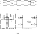
- a two-stage inverter circuit structure is usually used in an AC (Alternating current)-DC (Direct Current) argon arc welding machine in the market, as shown in figure 1 , a square wave AC with low voltage and high frequency is outputted after a voltage signal of the grid is rectified and filtered, is firstly inverted, and then is decreased through a high frequency transformer; and then a DC or an AC welding current having a lower frequency is outputted, after the square wave AC is further rectified and secondary inverted.
- AC Alternating current
- DC Direct Current
- a rectifying and secondary inverter circuit part after voltage decrease of a high frequency transformer in the prior art has two types, one type is a mode of a full-wave rectification circuit and a second full bridge inverter circuit, as shown in figure 2 , a low voltage high frequency AC passes through a full wave rectification circuit composed of a FRD (Fast Recovery Diode) D1, a FRD D2 and is converted into a low voltage DC, the low voltage DC continues to pass through a full bridge inverter circuit composed of VT1, VT2, VT3, VT4 and is converted into a low voltage DC or a low voltage low frequency AC, and the low voltage DC or low voltage low frequency AC is outputted by electric wire and is used for welding.
- FRD Flust Recovery Diode
- Another type is a mode of a bridge type rectification circuit having a centre tap and a secondary push-pull inverter circuit, as shown in figure 3 , a low voltage high frequency AC passes through a bridge type rectification circuit composed of FRDs D1, D2, D3, D4 and is converted into a low voltage DC, and then the low voltage DC passes through a push-pull inverter circuit composed of IGBT (Isolated Gate Bipolar Transistor) Q1, IGBT Q2 and is converted into a low voltage DC or low voltage low frequency AC, the low voltage DC or low voltage low frequency AC is outputted through the electric wire and is used for welding.
- IGBT Insulated Gate Bipolar Transistor
- a first problem is that an ordinary welding machine outputs low voltage high current, when the welding machine works, in a conducting loop, there are three conductive power devices (such as, D1+VT1+VT4, or D2+VT2+VT3, and so on), when an existing power device works, no matter the existing power device is a FRD or a IGBT or a field-effect tube, a voltage drop is always generated (generally speaking, the voltage drop is about 1-2V), the power device has an obvious power consumption especially when it lies in a large current state.
- a field-effect tube having a low voltage and a low on-resistance is widely used; however, there is a defection that the cost is high and a voltage protection circuit of the field-effect tube is more strictly required; moreover, aiming at a special characteristic of an electric arc welding workpiece, using of a low voltage field-effect tube is not good for electric arc maintenance when there is a current direction change, and an arc interruption phenomenon is prone to occur, thereby affecting a welding effect.
- a second problem is that, when there is the current direction change, in order to improve an arc stabilization effect, an optimized arc stabilization effect can be obtained when a voltage for arc stabilization is set to be about 250V; when a field-effect tube having a withstanding voltage less than 250V is used, an arc stabilization device is more complicated and the arc stabilization effect is bad; however, when a field-effect tube having a withstanding voltage more than 250V is used, there is always a much larger on-resistance, thereby resulting in an obvious power consumption.
- a third problem is that a large number of power devices need to be used, and a wire arrangement of an electric board is complicated.
- a second problem is that since the number of the FSDs is doubled, and the bridge type rectification circuit is used, when a high current occurs, a large space is occupied, and the wire arrangement of the electric board is complicated.
- a third problem is that a push-pull circuit is applied in the secondary inverter circuit, since withstanding voltage value of the power switches is doubled (generally, a voltage of 600V is selected), the existing welding machine usually adopts an IGBT of high withstanding voltage and heavy current, however, a high saturation voltage drop (1-2V) of this IGBT can results in a high power consumption.
- a four problem is that when the welding machine is in a DC output state, a condition that one group of power switches in the inverter circuit are continuously conductive and the other group of power switches in the inverter circuit are blocked will be happened, and thus it result inevitably that the power switches are traversed by heavy current. Therefore, when the bridge type rectification circuit having the centre tap and the secondary push-pull inverter circuit is designed, the number of the power switches and the capability of over current must be increased, which results in an increase in the cost inevitably, and also results in problems including an inhomogeneous heat dissipation of the heat sink and a bad heat dissipation effect.
- a purpose of the present invention is to provide a welding source and an AC-DC argon arc welding machine for the purpose of solving problems including a high power consumption of a traditional circuit structure, big heat sink and fan, a high cost, and a complicated wire arrangement, and achieving a goal of reducing weight and volume of the welding machine, reducing cost, and improving welding effect.
- the present invention provides a welding source connected between an input end of an AC and a welding workpiece, wherein the welding source comprises:
- the welding source further comprises:
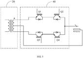
- the hybrid inverter unit comprises four IGBTs, the four IGBTs are IGBT Q1, IGBT Q2, IGBT Q3, and IGBT Q4 respectively; wherein an emitting electrode of the IGBT Q1 and a collecting electrode of the IGBT Q3 are connected to two windings of the transformer respectively, a collecting electrode of the IGBT Q1 and a collecting electrode of the IGBT Q2 are connected together, an emitting electrode of the IGBT Q3 and an emitting electrode of the IGBT Q4 are connected together, an emitting electrode of the IGBT Q2 and a collecting electrode of the IGBT Q4 are connected together to serve as an output end of the welding source, the four IGBTs control IGBTs Q1 and Q4 or IGBTs Q2 and Q3 to be on-off alternately by PWM drive pulses; a centre tap end of the transformer serves as another output end of the welding source.
- the hybrid inverter unit comprises four IGBT half-bridge modules.
- the present invention further provides an AC-DC argon arc welding machine, and the AC-DC argon arc welding machine comprises the aforesaid welding source in any form.
- the welding source and AC-DC argon arc welding machine provided by the present invention, by using an IGBT integrated internally with FRDs or an IGBT half-bridge module, a goal of combining a rectification function and a secondary inverting function as one is implemented, not only the types and the number of power devices are reduced, but also a difficulty of wire arrangement of an electric board is reduced; since a working time of each of power switches of the power circuit is always a half circle, the number of the power devices can be reduced by half in theory, even though IGBT or IGBT half bridge module of high withstanding voltage is used in the electric circuit, a power consumption generated by the electric circuit is still lower than that of a traditional circuit.
- a structure of an arc stabilization circuit can be much easier, a better arc stabilization effect can be obtained, and thus a better welding effect can be obtained, and power switches work under unbalanced states when the welding machine outputs DC can be avoided, and thus some problems such as a high power consumption of a traditional electric circuit structure, big heat sink and big fan, the high cost, and a complicated wire arrangement, and so on can be solved, and a goal of reducing a weight and a volume of the welding machine, and the cost, and improving a welding effect is achieved.
- FIG. 4 is a structural block diagram of a welding power provided by a preferred embodiment of the present invention, for convenient explanation, only the part relevant to this embodiment is illustrated, as shown in figure 4 :
- the welding power can also comprise a power supply switch 100 connected between the input end of the AC and the rectifying and wave-filtering unit 10 and configured for controlling on-off of the inputted AC.
- FIG. 5 is a structural schematic diagram of the hybrid inverter unit 40 in the welding power provided by one embodiment of the present invention; for convenient explanation, only the part relevant to this embodiment is illustrated, as shown in the figure:
- IGBTs Q1, Q4, or IGBTs Q2, Q3 are controlled to be on-off alternately, thereby achieving an AC output, that is, a simplified working principle of the hybrid inverter unit is similar to full-wave rectifying circuits of two kinds of diodes.
- the welding workpiece When the welding workpiece is in need of DC, it needs to set drive signals of IGBTs Q2 and Q3 or drive signals of IGBTs Q1 and Q4 to be high level; moreover, by switching drive signals of IGBTs Q2, Q3 or IGBTs Q1, Q4, the polarity of electric current outputted to the welding workpiece can also be switched.
- specific working principle of the welding machine is similar to that of the DC output, but driven of IGBTs is implemented by driving and controlling IGBTs Q2, Q3 or IGBTs Q1, Q4 to be on-off alternately through PWM drive pulses, such that the welding machine can output a low frequency AC, and an AC welding operation can be performed; moreover, by modulating a frequency and a duty ratio of a PWM drive pulse, a diversity of electric current wave form can be implemented, and a requirement of welding of metals, such as aluminum, magnesium, and metal alloy can be met.
- Figure 6 illustrates a structural schematic diagram of the hybrid inverter unit 40 in the welding power provided by another embodiment of the present invention; similarly, for convenient explanation, only the part relevant to this embodiment is illustrated, as shown in figure 6 :
- another embodiment of the present invention further provides an AC-DC argon arc welding machine, considered as an improvement, the AC-DC argon arc welding machine is provided therein with the welding power provided by any one of the aforesaid embodiments.
- the welding power and the AC-DC argon arc welding machine can be adapted to various power level inverter AC-DC argon arc welding machines, by using a plurality of single IGBTs of different numbers and connected in parallel, or IGBT half-bridge module(s), different application occasions can be met; besides, the welding power and the AC-DC argon arc welding machine are completely compatible to a drive circuit having a traditional secondary full-bridge inverter structure, and a transplantation can be conveniently implemented.
- use of FRDs for rectification is cancelled, types and numbers of power devices are reduced, the cost is reduced, the difficulty for repairing is reduced and an efficiency of assembly is improved.
- the power devices are always maintained at a balanced working state, and can generate heat evenly; the power devices and a heat dissipation device are efficiently utilized; with respect to a traditional structure, the number of the power devices are reduced by half theoretically.
- IGBTs having high voltage resistance are used in the power switches, and thus a design of an absorption circuit can be cancelled or simplified; the IGBTs have a higher reliability, and an arc stabilizing circuit can be designed more easily, so that an arc stabilizing effect is much better, which makes a welding effect be much better.
Landscapes
- Engineering & Computer Science (AREA)
- Physics & Mathematics (AREA)
- Plasma & Fusion (AREA)
- Mechanical Engineering (AREA)
- Power Engineering (AREA)
- Arc Welding Control (AREA)
- Inverter Devices (AREA)
- Generation Of Surge Voltage And Current (AREA)
- Lining Or Joining Of Plastics Or The Like (AREA)
Applications Claiming Priority (1)
| Application Number | Priority Date | Filing Date | Title |
|---|---|---|---|
| CN201610286861.XA CN105817740B (zh) | 2016-05-03 | 2016-05-03 | 焊接电源及交直流氩弧焊机 |
Publications (2)
| Publication Number | Publication Date |
|---|---|
| EP3241641A1 true EP3241641A1 (fr) | 2017-11-08 |
| EP3241641B1 EP3241641B1 (fr) | 2022-04-27 |
Family
ID=56527983
Family Applications (1)
| Application Number | Title | Priority Date | Filing Date |
|---|---|---|---|
| EP16201237.1A Active EP3241641B1 (fr) | 2016-05-03 | 2016-11-29 | Source de soudage avec ca et cc |
Country Status (7)
| Country | Link |
|---|---|
| US (1) | US10112250B2 (fr) |
| EP (1) | EP3241641B1 (fr) |
| CN (1) | CN105817740B (fr) |
| DK (1) | DK3241641T3 (fr) |
| ES (1) | ES2922804T3 (fr) |
| PL (1) | PL3241641T3 (fr) |
| PT (1) | PT3241641T (fr) |
Families Citing this family (11)
| Publication number | Priority date | Publication date | Assignee | Title |
|---|---|---|---|---|
| EP3727736B1 (fr) * | 2017-10-26 | 2022-06-29 | The Esab Group, Inc. | Système de soudage portatif et procédé faisant appel à des techniques pour fournir un courant de soudage ca ou cc |
| JP6993946B2 (ja) * | 2018-08-21 | 2022-01-14 | 株式会社東芝 | 半導体素子 |
| DE102019204794A1 (de) * | 2019-04-04 | 2020-10-08 | Robert Bosch Gmbh | Gleichrichter für einen Schweißtransformator einer Schweißvorrichtung und Verfahren zum Herstellen eines solchen Gleichrichters |
| CN110854732B (zh) * | 2019-10-28 | 2022-02-11 | 中国人民解放军96782部队 | 一种被覆作业低压数控电源保障平台 |
| CN111992857B (zh) * | 2020-09-10 | 2025-03-18 | 胡宝良 | 用于焊机的双单管电压嵌位二极管逆变双系统高频电路 |
| CN112600455B (zh) | 2020-12-07 | 2021-12-17 | 昱能科技股份有限公司 | 一种供电系统及太阳能光伏逆变器 |
| CN113210802B (zh) * | 2021-04-14 | 2022-11-18 | 上海广为焊接设备有限公司 | 一种用于交直流氩弧焊的辅助维弧电路和方法 |
| CN113210804A (zh) * | 2021-05-28 | 2021-08-06 | 广东集雅电器有限公司 | 一种直流焊接电路系统 |
| CN113691148A (zh) * | 2021-08-20 | 2021-11-23 | 深圳市佳士科技股份有限公司 | 电流方向切换电路、焊机驱动电路和焊机设备 |
| CN114012212B (zh) * | 2021-11-12 | 2025-05-30 | 成都振中科技有限公司 | 一种交直流复合弧焊电源、焊接系统及控制方法 |
| CN116155065A (zh) * | 2023-02-24 | 2023-05-23 | 广州锐速智能科技股份有限公司 | 一种高压隔离电源系统 |
Citations (6)
| Publication number | Priority date | Publication date | Assignee | Title |
|---|---|---|---|---|
| EP0977347A2 (fr) * | 1994-03-03 | 2000-02-02 | Miller Electric Manufacturing Company | Système de puissance commandable |
| US20090039063A1 (en) * | 2007-08-10 | 2009-02-12 | Madsen Michael D | Power supply configured to deliver ac welding-type power |
| US20120120687A1 (en) * | 2009-05-27 | 2012-05-17 | Panasonic Corporation | Inverter control device and inverter control method |
| US20140083987A1 (en) * | 2012-09-24 | 2014-03-27 | Robert L. Dodge | Systems and methods providing controlled ac arc welding processes |
| US20140209586A1 (en) * | 2013-01-29 | 2014-07-31 | Shenzhen Jasic Technology Development Co., Ltd | Portable igbt arc welding machine |
| US20140268893A1 (en) * | 2013-03-15 | 2014-09-18 | Illinois Tool Works Inc. | Method and Apparatus For Soft Switching Welding Type Power |
Family Cites Families (10)
| Publication number | Priority date | Publication date | Assignee | Title |
|---|---|---|---|---|
| CN1745952A (zh) * | 2005-10-14 | 2006-03-15 | 北京工业大学 | 一种解决变极性等离子弧焊接双弧的电路 |
| US9789559B2 (en) * | 2007-10-22 | 2017-10-17 | Illinois Tool Works, Inc. | System and method for controlling multiple processes in a welding-type power source using a refined controller architecture |
| CN102044973B (zh) * | 2009-10-23 | 2014-05-07 | 罗克韦尔自动化控制集成(哈尔滨)有限公司 | 一种二极管箝位式三电平变频器 |
| HK1203108A1 (en) * | 2012-02-09 | 2015-10-16 | 株式会社泰库诺瓦 | Bidirectional contactless power supply system |
| JP5538658B2 (ja) * | 2012-05-24 | 2014-07-02 | 三菱電機株式会社 | 電力変換装置 |
| JP6243801B2 (ja) * | 2014-06-12 | 2017-12-06 | 株式会社日立製作所 | 電力変換装置 |
| EP3259840A1 (fr) * | 2015-02-18 | 2017-12-27 | GE Aviation Systems LLC | Système de production et de démarrage d'aéronef |
| DE112016001372T8 (de) * | 2015-03-25 | 2018-01-11 | Sunpower Corporation | Umwandlertopologien für Gleichtaktspannungsreduzierung |
| US10549374B2 (en) * | 2015-12-31 | 2020-02-04 | Illinois Tool Works Inc. | Welding power supply with half bridge |
| CN205614170U (zh) * | 2016-05-03 | 2016-10-05 | 深圳市佳士科技股份有限公司 | 焊接电源及交直流氩弧焊机 |
-
2016
- 2016-05-03 CN CN201610286861.XA patent/CN105817740B/zh active Active
- 2016-11-29 ES ES16201237T patent/ES2922804T3/es active Active
- 2016-11-29 PL PL16201237.1T patent/PL3241641T3/pl unknown
- 2016-11-29 EP EP16201237.1A patent/EP3241641B1/fr active Active
- 2016-11-29 DK DK16201237.1T patent/DK3241641T3/da active
- 2016-11-29 PT PT162012371T patent/PT3241641T/pt unknown
- 2016-11-30 US US15/364,575 patent/US10112250B2/en active Active
Patent Citations (6)
| Publication number | Priority date | Publication date | Assignee | Title |
|---|---|---|---|---|
| EP0977347A2 (fr) * | 1994-03-03 | 2000-02-02 | Miller Electric Manufacturing Company | Système de puissance commandable |
| US20090039063A1 (en) * | 2007-08-10 | 2009-02-12 | Madsen Michael D | Power supply configured to deliver ac welding-type power |
| US20120120687A1 (en) * | 2009-05-27 | 2012-05-17 | Panasonic Corporation | Inverter control device and inverter control method |
| US20140083987A1 (en) * | 2012-09-24 | 2014-03-27 | Robert L. Dodge | Systems and methods providing controlled ac arc welding processes |
| US20140209586A1 (en) * | 2013-01-29 | 2014-07-31 | Shenzhen Jasic Technology Development Co., Ltd | Portable igbt arc welding machine |
| US20140268893A1 (en) * | 2013-03-15 | 2014-09-18 | Illinois Tool Works Inc. | Method and Apparatus For Soft Switching Welding Type Power |
Also Published As
| Publication number | Publication date |
|---|---|
| ES2922804T3 (es) | 2022-09-20 |
| EP3241641B1 (fr) | 2022-04-27 |
| PL3241641T3 (pl) | 2022-08-01 |
| DK3241641T3 (da) | 2022-07-18 |
| CN105817740B (zh) | 2018-05-01 |
| PT3241641T (pt) | 2022-07-26 |
| CN105817740A (zh) | 2016-08-03 |
| US10112250B2 (en) | 2018-10-30 |
| US20170320157A1 (en) | 2017-11-09 |
Similar Documents
| Publication | Publication Date | Title |
|---|---|---|
| US10112250B2 (en) | Welding source and AC-DC argon arc welding machine | |
| CN107888100B (zh) | 一种逆变器、控制逆变器的方法及控制装置 | |
| US9148072B2 (en) | Inverter apparatus | |
| CN107086770B (zh) | Pfc电路及变频空调器 | |
| CN107318272B (zh) | 半导体装置 | |
| US20140376294A1 (en) | Single-Phase Inverter and Three-Phase Inverter | |
| CN105493388B (zh) | 电力变换装置 | |
| US10498256B2 (en) | Multi-level inverter with synchronous rectification technology | |
| CN100460122C (zh) | 超快变换变极性方波电流弧焊电源装置 | |
| WO2016119736A1 (fr) | Unité de topologie à cinq niveaux et onduleur à cinq niveaux | |
| CN107104589B (zh) | Pfc电路及变频空调器 | |
| CN102806407B (zh) | 一种逆变焊机 | |
| US8587266B2 (en) | Synchronous regulation circuit for turn-on and turn-off phase angle of the AC voltage | |
| CN109980981B (zh) | 基于主动旁路及对称调制的混合型mmc热应力不均平抑方法 | |
| TWI539736B (zh) | 五電平變換裝置 | |
| EP2662966B1 (fr) | Onduleur à trois niveaux | |
| CN108602150B (zh) | 用于有效地提供弧焊电源的系统和方法 | |
| CN104601002B (zh) | 一种稀疏式双级矩阵变换器拓扑结构 | |
| CN113972830A (zh) | 图腾柱功率因数校正电路、控制方法、装置及设备 | |
| JP2016208693A (ja) | 電力変換装置 | |
| CN205614170U (zh) | 焊接电源及交直流氩弧焊机 | |
| CN210536518U (zh) | 高压辅助电源及高压辅助电源控制系统 | |
| CN209767411U (zh) | 一种变流电路 | |
| CN107994779A (zh) | 一种推挽式开关电源拓扑结构 | |
| CN106817042B (zh) | Dc-ac变换器及其控制方法 |
Legal Events
| Date | Code | Title | Description |
|---|---|---|---|
| PUAI | Public reference made under article 153(3) epc to a published international application that has entered the european phase |
Free format text: ORIGINAL CODE: 0009012 |
|
| STAA | Information on the status of an ep patent application or granted ep patent |
Free format text: STATUS: REQUEST FOR EXAMINATION WAS MADE |
|
| 17P | Request for examination filed |
Effective date: 20161201 |
|
| AK | Designated contracting states |
Kind code of ref document: A1 Designated state(s): AL AT BE BG CH CY CZ DE DK EE ES FI FR GB GR HR HU IE IS IT LI LT LU LV MC MK MT NL NO PL PT RO RS SE SI SK SM TR |
|
| AX | Request for extension of the european patent |
Extension state: BA ME |
|
| STAA | Information on the status of an ep patent application or granted ep patent |
Free format text: STATUS: EXAMINATION IS IN PROGRESS |
|
| 17Q | First examination report despatched |
Effective date: 20190425 |
|
| GRAP | Despatch of communication of intention to grant a patent |
Free format text: ORIGINAL CODE: EPIDOSNIGR1 |
|
| STAA | Information on the status of an ep patent application or granted ep patent |
Free format text: STATUS: GRANT OF PATENT IS INTENDED |
|
| INTG | Intention to grant announced |
Effective date: 20211215 |
|
| GRAS | Grant fee paid |
Free format text: ORIGINAL CODE: EPIDOSNIGR3 |
|
| GRAA | (expected) grant |
Free format text: ORIGINAL CODE: 0009210 |
|
| STAA | Information on the status of an ep patent application or granted ep patent |
Free format text: STATUS: THE PATENT HAS BEEN GRANTED |
|
| AK | Designated contracting states |
Kind code of ref document: B1 Designated state(s): AL AT BE BG CH CY CZ DE DK EE ES FI FR GB GR HR HU IE IS IT LI LT LU LV MC MK MT NL NO PL PT RO RS SE SI SK SM TR |
|
| REG | Reference to a national code |
Ref country code: GB Ref legal event code: FG4D |
|
| REG | Reference to a national code |
Ref country code: CH Ref legal event code: EP |
|
| REG | Reference to a national code |
Ref country code: DE Ref legal event code: R096 Ref document number: 602016071457 Country of ref document: DE |
|
| REG | Reference to a national code |
Ref country code: AT Ref legal event code: REF Ref document number: 1486557 Country of ref document: AT Kind code of ref document: T Effective date: 20220515 |
|
| REG | Reference to a national code |
Ref country code: IE Ref legal event code: FG4D |
|
| REG | Reference to a national code |
Ref country code: DK Ref legal event code: T3 Effective date: 20220713 |
|
| REG | Reference to a national code |
Ref country code: NL Ref legal event code: FP |
|
| REG | Reference to a national code |
Ref country code: FI Ref legal event code: FGE |
|
| REG | Reference to a national code |
Ref country code: PT Ref legal event code: SC4A Ref document number: 3241641 Country of ref document: PT Date of ref document: 20220726 Kind code of ref document: T Free format text: AVAILABILITY OF NATIONAL TRANSLATION Effective date: 20220712 |
|
| REG | Reference to a national code |
Ref country code: SE Ref legal event code: TRGR |
|
| REG | Reference to a national code |
Ref country code: LT Ref legal event code: MG9D |
|
| REG | Reference to a national code |
Ref country code: ES Ref legal event code: FG2A Ref document number: 2922804 Country of ref document: ES Kind code of ref document: T3 Effective date: 20220920 |
|
| REG | Reference to a national code |
Ref country code: GR Ref legal event code: EP Ref document number: 20220401533 Country of ref document: GR Effective date: 20221010 |
|
| PG25 | Lapsed in a contracting state [announced via postgrant information from national office to epo] |
Ref country code: NO Free format text: LAPSE BECAUSE OF FAILURE TO SUBMIT A TRANSLATION OF THE DESCRIPTION OR TO PAY THE FEE WITHIN THE PRESCRIBED TIME-LIMIT Effective date: 20220727 Ref country code: LT Free format text: LAPSE BECAUSE OF FAILURE TO SUBMIT A TRANSLATION OF THE DESCRIPTION OR TO PAY THE FEE WITHIN THE PRESCRIBED TIME-LIMIT Effective date: 20220427 Ref country code: HR Free format text: LAPSE BECAUSE OF FAILURE TO SUBMIT A TRANSLATION OF THE DESCRIPTION OR TO PAY THE FEE WITHIN THE PRESCRIBED TIME-LIMIT Effective date: 20220427 Ref country code: BG Free format text: LAPSE BECAUSE OF FAILURE TO SUBMIT A TRANSLATION OF THE DESCRIPTION OR TO PAY THE FEE WITHIN THE PRESCRIBED TIME-LIMIT Effective date: 20220727 |
|
| PG25 | Lapsed in a contracting state [announced via postgrant information from national office to epo] |
Ref country code: RS Free format text: LAPSE BECAUSE OF FAILURE TO SUBMIT A TRANSLATION OF THE DESCRIPTION OR TO PAY THE FEE WITHIN THE PRESCRIBED TIME-LIMIT Effective date: 20220427 Ref country code: LV Free format text: LAPSE BECAUSE OF FAILURE TO SUBMIT A TRANSLATION OF THE DESCRIPTION OR TO PAY THE FEE WITHIN THE PRESCRIBED TIME-LIMIT Effective date: 20220427 Ref country code: IS Free format text: LAPSE BECAUSE OF FAILURE TO SUBMIT A TRANSLATION OF THE DESCRIPTION OR TO PAY THE FEE WITHIN THE PRESCRIBED TIME-LIMIT Effective date: 20220827 |
|
| REG | Reference to a national code |
Ref country code: DE Ref legal event code: R097 Ref document number: 602016071457 Country of ref document: DE |
|
| PG25 | Lapsed in a contracting state [announced via postgrant information from national office to epo] |
Ref country code: SM Free format text: LAPSE BECAUSE OF FAILURE TO SUBMIT A TRANSLATION OF THE DESCRIPTION OR TO PAY THE FEE WITHIN THE PRESCRIBED TIME-LIMIT Effective date: 20220427 Ref country code: SK Free format text: LAPSE BECAUSE OF FAILURE TO SUBMIT A TRANSLATION OF THE DESCRIPTION OR TO PAY THE FEE WITHIN THE PRESCRIBED TIME-LIMIT Effective date: 20220427 Ref country code: RO Free format text: LAPSE BECAUSE OF FAILURE TO SUBMIT A TRANSLATION OF THE DESCRIPTION OR TO PAY THE FEE WITHIN THE PRESCRIBED TIME-LIMIT Effective date: 20220427 Ref country code: EE Free format text: LAPSE BECAUSE OF FAILURE TO SUBMIT A TRANSLATION OF THE DESCRIPTION OR TO PAY THE FEE WITHIN THE PRESCRIBED TIME-LIMIT Effective date: 20220427 Ref country code: CZ Free format text: LAPSE BECAUSE OF FAILURE TO SUBMIT A TRANSLATION OF THE DESCRIPTION OR TO PAY THE FEE WITHIN THE PRESCRIBED TIME-LIMIT Effective date: 20220427 |
|
| PLBE | No opposition filed within time limit |
Free format text: ORIGINAL CODE: 0009261 |
|
| STAA | Information on the status of an ep patent application or granted ep patent |
Free format text: STATUS: NO OPPOSITION FILED WITHIN TIME LIMIT |
|
| PG25 | Lapsed in a contracting state [announced via postgrant information from national office to epo] |
Ref country code: AL Free format text: LAPSE BECAUSE OF FAILURE TO SUBMIT A TRANSLATION OF THE DESCRIPTION OR TO PAY THE FEE WITHIN THE PRESCRIBED TIME-LIMIT Effective date: 20220427 |
|
| 26N | No opposition filed |
Effective date: 20230130 |
|
| PG25 | Lapsed in a contracting state [announced via postgrant information from national office to epo] |
Ref country code: SI Free format text: LAPSE BECAUSE OF FAILURE TO SUBMIT A TRANSLATION OF THE DESCRIPTION OR TO PAY THE FEE WITHIN THE PRESCRIBED TIME-LIMIT Effective date: 20220427 |
|
| PG25 | Lapsed in a contracting state [announced via postgrant information from national office to epo] |
Ref country code: MC Free format text: LAPSE BECAUSE OF FAILURE TO SUBMIT A TRANSLATION OF THE DESCRIPTION OR TO PAY THE FEE WITHIN THE PRESCRIBED TIME-LIMIT Effective date: 20220427 |
|
| REG | Reference to a national code |
Ref country code: CH Ref legal event code: PL |
|
| PG25 | Lapsed in a contracting state [announced via postgrant information from national office to epo] |
Ref country code: LI Free format text: LAPSE BECAUSE OF NON-PAYMENT OF DUE FEES Effective date: 20221130 Ref country code: CH Free format text: LAPSE BECAUSE OF NON-PAYMENT OF DUE FEES Effective date: 20221130 |
|
| PGFP | Annual fee paid to national office [announced via postgrant information from national office to epo] |
Ref country code: NL Payment date: 20231120 Year of fee payment: 8 Ref country code: LU Payment date: 20231120 Year of fee payment: 8 |
|
| PGFP | Annual fee paid to national office [announced via postgrant information from national office to epo] |
Ref country code: GR Payment date: 20231121 Year of fee payment: 8 |
|
| PGFP | Annual fee paid to national office [announced via postgrant information from national office to epo] |
Ref country code: TR Payment date: 20231127 Year of fee payment: 8 Ref country code: SE Payment date: 20231120 Year of fee payment: 8 Ref country code: PT Payment date: 20231116 Year of fee payment: 8 Ref country code: IE Payment date: 20231121 Year of fee payment: 8 Ref country code: FI Payment date: 20231121 Year of fee payment: 8 Ref country code: DK Payment date: 20231124 Year of fee payment: 8 Ref country code: AT Payment date: 20231121 Year of fee payment: 8 |
|
| PGFP | Annual fee paid to national office [announced via postgrant information from national office to epo] |
Ref country code: PL Payment date: 20231120 Year of fee payment: 8 Ref country code: BE Payment date: 20231120 Year of fee payment: 8 |
|
| PG25 | Lapsed in a contracting state [announced via postgrant information from national office to epo] |
Ref country code: HU Free format text: LAPSE BECAUSE OF FAILURE TO SUBMIT A TRANSLATION OF THE DESCRIPTION OR TO PAY THE FEE WITHIN THE PRESCRIBED TIME-LIMIT; INVALID AB INITIO Effective date: 20161129 |
|
| PGFP | Annual fee paid to national office [announced via postgrant information from national office to epo] |
Ref country code: ES Payment date: 20240129 Year of fee payment: 8 |
|
| PG25 | Lapsed in a contracting state [announced via postgrant information from national office to epo] |
Ref country code: CY Free format text: LAPSE BECAUSE OF FAILURE TO SUBMIT A TRANSLATION OF THE DESCRIPTION OR TO PAY THE FEE WITHIN THE PRESCRIBED TIME-LIMIT Effective date: 20220427 |
|
| PG25 | Lapsed in a contracting state [announced via postgrant information from national office to epo] |
Ref country code: MK Free format text: LAPSE BECAUSE OF FAILURE TO SUBMIT A TRANSLATION OF THE DESCRIPTION OR TO PAY THE FEE WITHIN THE PRESCRIBED TIME-LIMIT Effective date: 20220427 |
|
| PG25 | Lapsed in a contracting state [announced via postgrant information from national office to epo] |
Ref country code: MT Free format text: LAPSE BECAUSE OF FAILURE TO SUBMIT A TRANSLATION OF THE DESCRIPTION OR TO PAY THE FEE WITHIN THE PRESCRIBED TIME-LIMIT Effective date: 20220427 |
|
| PG25 | Lapsed in a contracting state [announced via postgrant information from national office to epo] |
Ref country code: BG Free format text: LAPSE BECAUSE OF FAILURE TO SUBMIT A TRANSLATION OF THE DESCRIPTION OR TO PAY THE FEE WITHIN THE PRESCRIBED TIME-LIMIT Effective date: 20220427 |
|
| PG25 | Lapsed in a contracting state [announced via postgrant information from national office to epo] |
Ref country code: BG Free format text: LAPSE BECAUSE OF FAILURE TO SUBMIT A TRANSLATION OF THE DESCRIPTION OR TO PAY THE FEE WITHIN THE PRESCRIBED TIME-LIMIT Effective date: 20220427 |
|
| REG | Reference to a national code |
Ref country code: DK Ref legal event code: EBP Effective date: 20241130 |
|
| REG | Reference to a national code |
Ref country code: SE Ref legal event code: EUG |
|
| PG25 | Lapsed in a contracting state [announced via postgrant information from national office to epo] |
Ref country code: FI Free format text: LAPSE BECAUSE OF NON-PAYMENT OF DUE FEES Effective date: 20241129 |
|
| REG | Reference to a national code |
Ref country code: NL Ref legal event code: MM Effective date: 20241201 |
|
| PG25 | Lapsed in a contracting state [announced via postgrant information from national office to epo] |
Ref country code: LU Free format text: LAPSE BECAUSE OF NON-PAYMENT OF DUE FEES Effective date: 20241129 |
|
| REG | Reference to a national code |
Ref country code: AT Ref legal event code: MM01 Ref document number: 1486557 Country of ref document: AT Kind code of ref document: T Effective date: 20241129 |
|
| PG25 | Lapsed in a contracting state [announced via postgrant information from national office to epo] |
Ref country code: PT Free format text: LAPSE BECAUSE OF NON-PAYMENT OF DUE FEES Effective date: 20250529 |
|
| PG25 | Lapsed in a contracting state [announced via postgrant information from national office to epo] |
Ref country code: GR Free format text: LAPSE BECAUSE OF NON-PAYMENT OF DUE FEES Effective date: 20250610 |
|
| PG25 | Lapsed in a contracting state [announced via postgrant information from national office to epo] |
Ref country code: AT Free format text: LAPSE BECAUSE OF NON-PAYMENT OF DUE FEES Effective date: 20241129 |
|
| PG25 | Lapsed in a contracting state [announced via postgrant information from national office to epo] |
Ref country code: NL Free format text: LAPSE BECAUSE OF NON-PAYMENT OF DUE FEES Effective date: 20241201 |
|
| REG | Reference to a national code |
Ref country code: BE Ref legal event code: MM Effective date: 20241130 |
|
| PG25 | Lapsed in a contracting state [announced via postgrant information from national office to epo] |
Ref country code: DK Free format text: LAPSE BECAUSE OF NON-PAYMENT OF DUE FEES Effective date: 20241130 |
|
| PG25 | Lapsed in a contracting state [announced via postgrant information from national office to epo] |
Ref country code: SE Free format text: LAPSE BECAUSE OF NON-PAYMENT OF DUE FEES Effective date: 20241130 |
|
| PG25 | Lapsed in a contracting state [announced via postgrant information from national office to epo] |
Ref country code: BE Free format text: LAPSE BECAUSE OF NON-PAYMENT OF DUE FEES Effective date: 20241130 |
|
| PG25 | Lapsed in a contracting state [announced via postgrant information from national office to epo] |
Ref country code: IE Free format text: LAPSE BECAUSE OF NON-PAYMENT OF DUE FEES Effective date: 20241129 |
|
| REG | Reference to a national code |
Ref country code: ES Ref legal event code: FD2A Effective date: 20260107 |
|
| PGFP | Annual fee paid to national office [announced via postgrant information from national office to epo] |
Ref country code: GB Payment date: 20251117 Year of fee payment: 10 |
|
| PGFP | Annual fee paid to national office [announced via postgrant information from national office to epo] |
Ref country code: IT Payment date: 20251127 Year of fee payment: 10 |
|
| PGFP | Annual fee paid to national office [announced via postgrant information from national office to epo] |
Ref country code: FR Payment date: 20251127 Year of fee payment: 10 |
|
| PG25 | Lapsed in a contracting state [announced via postgrant information from national office to epo] |
Ref country code: ES Free format text: LAPSE BECAUSE OF NON-PAYMENT OF DUE FEES Effective date: 20241130 |
|
| PGFP | Annual fee paid to national office [announced via postgrant information from national office to epo] |
Ref country code: DE Payment date: 20251222 Year of fee payment: 10 |
|
| PG25 | Lapsed in a contracting state [announced via postgrant information from national office to epo] |
Ref country code: PL Free format text: LAPSE BECAUSE OF NON-PAYMENT OF DUE FEES Effective date: 20241129 |