EP3727736B1 - Système de soudage portatif et procédé faisant appel à des techniques pour fournir un courant de soudage ca ou cc - Google Patents
Système de soudage portatif et procédé faisant appel à des techniques pour fournir un courant de soudage ca ou cc Download PDFInfo
- Publication number
- EP3727736B1 EP3727736B1 EP18807753.1A EP18807753A EP3727736B1 EP 3727736 B1 EP3727736 B1 EP 3727736B1 EP 18807753 A EP18807753 A EP 18807753A EP 3727736 B1 EP3727736 B1 EP 3727736B1
- Authority
- EP
- European Patent Office
- Prior art keywords
- welding
- voltage
- output
- welding current
- portable
- Prior art date
- Legal status (The legal status is an assumption and is not a legal conclusion. Google has not performed a legal analysis and makes no representation as to the accuracy of the status listed.)
- Not-in-force
Links
Images






Classifications
-
- B—PERFORMING OPERATIONS; TRANSPORTING
- B23—MACHINE TOOLS; METAL-WORKING NOT OTHERWISE PROVIDED FOR
- B23K—SOLDERING OR UNSOLDERING; WELDING; CLADDING OR PLATING BY SOLDERING OR WELDING; CUTTING BY APPLYING HEAT LOCALLY, e.g. FLAME CUTTING; WORKING BY LASER BEAM
- B23K9/00—Arc welding or cutting
- B23K9/095—Monitoring or automatic control of welding parameters
- B23K9/0953—Monitoring or automatic control of welding parameters using computing means
-
- B—PERFORMING OPERATIONS; TRANSPORTING
- B23—MACHINE TOOLS; METAL-WORKING NOT OTHERWISE PROVIDED FOR
- B23K—SOLDERING OR UNSOLDERING; WELDING; CLADDING OR PLATING BY SOLDERING OR WELDING; CUTTING BY APPLYING HEAT LOCALLY, e.g. FLAME CUTTING; WORKING BY LASER BEAM
- B23K9/00—Arc welding or cutting
- B23K9/10—Other electric circuits therefor; Protective circuits; Remote controls
- B23K9/1006—Power supply
- B23K9/1043—Power supply characterised by the electric circuit
-
- B—PERFORMING OPERATIONS; TRANSPORTING
- B23—MACHINE TOOLS; METAL-WORKING NOT OTHERWISE PROVIDED FOR
- B23K—SOLDERING OR UNSOLDERING; WELDING; CLADDING OR PLATING BY SOLDERING OR WELDING; CUTTING BY APPLYING HEAT LOCALLY, e.g. FLAME CUTTING; WORKING BY LASER BEAM
- B23K9/00—Arc welding or cutting
- B23K9/09—Arrangements or circuits for arc welding with pulsed current or voltage
- B23K9/091—Arrangements or circuits for arc welding with pulsed current or voltage characterised by the circuits
-
- B—PERFORMING OPERATIONS; TRANSPORTING
- B23—MACHINE TOOLS; METAL-WORKING NOT OTHERWISE PROVIDED FOR
- B23K—SOLDERING OR UNSOLDERING; WELDING; CLADDING OR PLATING BY SOLDERING OR WELDING; CUTTING BY APPLYING HEAT LOCALLY, e.g. FLAME CUTTING; WORKING BY LASER BEAM
- B23K9/00—Arc welding or cutting
- B23K9/10—Other electric circuits therefor; Protective circuits; Remote controls
- B23K9/1006—Power supply
- B23K9/1043—Power supply characterised by the electric circuit
- B23K9/1056—Power supply characterised by the electric circuit by using digital means
- B23K9/1062—Power supply characterised by the electric circuit by using digital means with computing means
-
- B—PERFORMING OPERATIONS; TRANSPORTING
- B23—MACHINE TOOLS; METAL-WORKING NOT OTHERWISE PROVIDED FOR
- B23K—SOLDERING OR UNSOLDERING; WELDING; CLADDING OR PLATING BY SOLDERING OR WELDING; CUTTING BY APPLYING HEAT LOCALLY, e.g. FLAME CUTTING; WORKING BY LASER BEAM
- B23K9/00—Arc welding or cutting
- B23K9/10—Other electric circuits therefor; Protective circuits; Remote controls
- B23K9/1006—Power supply
- B23K9/1043—Power supply characterised by the electric circuit
- B23K9/1068—Electric circuits for the supply of power to two or more arcs from a single source
-
- B—PERFORMING OPERATIONS; TRANSPORTING
- B23—MACHINE TOOLS; METAL-WORKING NOT OTHERWISE PROVIDED FOR
- B23K—SOLDERING OR UNSOLDERING; WELDING; CLADDING OR PLATING BY SOLDERING OR WELDING; CUTTING BY APPLYING HEAT LOCALLY, e.g. FLAME CUTTING; WORKING BY LASER BEAM
- B23K9/00—Arc welding or cutting
- B23K9/12—Automatic feeding or moving of electrodes or work for spot or seam welding or cutting
-
- B—PERFORMING OPERATIONS; TRANSPORTING
- B23—MACHINE TOOLS; METAL-WORKING NOT OTHERWISE PROVIDED FOR
- B23K—SOLDERING OR UNSOLDERING; WELDING; CLADDING OR PLATING BY SOLDERING OR WELDING; CUTTING BY APPLYING HEAT LOCALLY, e.g. FLAME CUTTING; WORKING BY LASER BEAM
- B23K9/00—Arc welding or cutting
- B23K9/16—Arc welding or cutting making use of shielding gas
- B23K9/167—Arc welding or cutting making use of shielding gas and of a non-consumable electrode
-
- B—PERFORMING OPERATIONS; TRANSPORTING
- B23—MACHINE TOOLS; METAL-WORKING NOT OTHERWISE PROVIDED FOR
- B23K—SOLDERING OR UNSOLDERING; WELDING; CLADDING OR PLATING BY SOLDERING OR WELDING; CUTTING BY APPLYING HEAT LOCALLY, e.g. FLAME CUTTING; WORKING BY LASER BEAM
- B23K9/00—Arc welding or cutting
- B23K9/16—Arc welding or cutting making use of shielding gas
- B23K9/173—Arc welding or cutting making use of shielding gas and of a consumable electrode
Definitions
- the present disclosure generally relates to welding and cutting equipment and, more particularly, to AC-DC control techniques in a portable, multi-process welding and cutting machine, and more particularly to a portable welding system and a method, see claims 1 and 10.
- Portable welding and cutting systems are known, and often incorporate a power supply and related mechanisms (e.g., wire feeder, wire spool) in a portable case.
- Such portable welding systems find use in applications where it is not practical or convenient to send a work-piece to a shop for repair or fabrication. Examples of applications for such portable welding systems include petroleum and chemical equipment fabrication, shipboard installation and repair, and the like.
- known portable welding systems may be relatively lightweight to enable a user to lift and carry the system to a work site.
- US 2012/241429 A1 (basis for the preamble of claims 1 and 10) describes a method for setting welding parameters.
- the method includes receiving an input relating to a change in a parameter of welding power of a welding system via a welding system interface.
- the method also includes displaying a graphical representation of an acceptable range of values for the parameter of the welding power on a display device of the welding system interface, wherein the acceptable range of values is based on other parameters of a welding process being performed by the welding system.
- the method further includes constraining subsequent manual inputs relating to changes in the parameter of the welding power to the acceptable range of values.
- KR 2011 0072809 A describes a power supply device for a composite welder and a control method thereof are provided to perform the welding of a selected mode among multiple welding modes depending on the control of a PWM control unit.
- a portable welding system and a method according to the present invention are listed in claims 1 and 10 respectively.
- Embodiments described herein combine, at least, the following welding processes in a single compact unit: (1) stick, (2) AC and DC TIG, and (3) MIG (with internal spool), that are all selectable and controllable via a graphical user interface (GUI) that enables a user to easily choose from among the different processes, and configure parameters for a given selected process.
- GUI graphical user interface
- a multi-process welding machine provides an intuitive user interface to enable a user to select among different welding processes, and to select parameters for a given selected welding process.
- the multi-process welding machine also provides an arrangement by which a switching module, or DC to AC converter, of an AC TIG unit can be controlled to alternatively supply AC or DC welding current (voltage) depending on the welding process selected.
- the configuration of switches can be leveraged to automatically (or manually) control the polarity of welding cables for different processes and to engage or to disengage a wire feeder when, e.g., MIG welding is selected, or not selected, as the case may be.
- ferrite or magnetic materials used for a main output inductor and an HF starting inductor of the welding machine can be combined to achieve cost and weight savings.
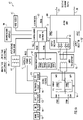
- FIG. 1A is a block diagram of a multi-process welding machine 100 in accordance with an example embodiment.
- machine 100 includes a mains input 101, an electromagnetic interference (EMI) filter 102 and an input rectifier 103.
- EMI electromagnetic interference
- the output of input rectifier 103 is connected, via an isolating transformer 115, to a main control board 120 that, among other possible functions, monitors an input voltage range from an output of the input rectifier 103.
- Input rectifier 103 also provides its output to a pre-charge circuit 104, whose output is fed to power factor control (PFC) circuit 105 and to internal power supply (IPS) 110, which generates a voltage supply signal named "IPS Sec.”
- IPS Sec is used to supply power to other components, including control board 120 and AC TIG unit 200, which are discussed below.
- the output of PFC circuit 105 may be referred to as the "DC Bus Voltage” and is supplied to a full bridge converter 130, which converts the DC Bus Voltage to an AC voltage V 1 that is fed to main transformer 135. Conversion of the DC Bus Voltage to AC is controlled via pulse wave modulated (PWM) signals PWM A, PWM B that are generated by PWM controller 121, which may be part of main control board 120. PWM signals PWM A, PWM B are supplied to pulse transformer 125, which generates signals PWM 1, PWM 2, PWM 3 and PWM 4 to switch respective IGBT switches SW1, SW2, SW3, SW4, in full bridge converter 130, the output of which is fed to main transformer 135.
- the various PWM signals can be arranged to generate a relatively high frequency (e.g., 100Hz - 47KHz) that enables main transformer 135 to have a smaller, and thus lighter, footprint.
- a broken line 190 indicates a demarcation between a high voltage/low current side of welding machine 100 and a low voltage/high current side of welding machine 100.
- the two sides are kept electrically isolated from each other.
- a user interface 150 including a graphical display, is in communication with main control board 120 and enables a user to select among multiple possible welding processes, and parameters for a given selected welding process.
- a wire feeder 160 whose drive motor is controlled by main control board 120 is provided for, e.g., a MIG welding process.
- a gun trigger input signal 123 is provided to control board 120 to trigger the control board to initiate and maintain an appropriate welding voltage/current (or high frequency start signal) generated by machine 100.
- AC TIG unit 200 is provided.
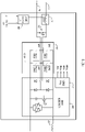
- AC TIG unit 200 described in more detail in connection with FIG. 1B , is connected to an output of output rectifier 140 and thus receives a rectified voltage from an output of main transformer 135.
- Output inductor 137 is disposed between a center tap of main transformer 135 and AC TIG unit 200.
- AC TIG unit 200 passes all welding current to welding cables 201, 202, regardless of the type of process being used.
- AC TIG unit 200 receives a signal PWM C from control board 120 that controls the frequency and duty cycle of the AC current generated by the AC TIG unit 200.
- IPS Sec also provided to AC TIG unit 200.
- AC TIG unit 200 is configured to receive an output of output rectifier 140, and output at least one of a DC welding current or an AC welding current according to input received via the graphical user interface.
- the DC welding current passes through at least one electronic switching device configured to generate the AC welding current.
- AC TIG unit 200 includes an AC inverter board 210, a PWM driver 212, a full bridge converter (or switching module) 215 including switches SW7, SW8, SW9, SW10 that are driven by PWM signals PWM 7, PWM 8, PWM 9, PWM 10, respectively, a high frequency (HF) start circuit 230 and associated HF inductor 270.
- AC inverter board 210 generates and supplies pulse wave modulated signals PWM 7, PWM 8, PWM 9, PWM 10 to respective IGBT switches SW 7, SW 8, SW 9, SW 10 in full bridge converter or switching module 215 to convert the supplied DC voltage from output rectifier 140 to AC voltage used for, e.g., AC TIG welding.
- An HF bypass circuit 275 comprising, e.g., suitable capacitors is provided to keep HF signals from interfering with electronics in the AC TIG unit 200.
- DC welding current supplied from output rectifier 140 passes through AC TIG unit 200.
- AC TIG unit 200 by manipulating switches in full bridge converter 215, can be configured to pass that DC welding current, without any further manipulation thereof, to welding cables 201, 202 for DC welding processes, or to convert the DC welding current to a desired AC current for AC welding processes.
- FIGs. 2 and 3A -3F depict example screen shots, which may be displayed on a graphical user interface 150, for selecting a given welding process in accordance with an example embodiment.
- the graphical user interface 150 is controlled by a user via a selector knob (not shown), which, when turned, successively highlights a given icon that corresponds to a given welding process or welding parameter.
- a selector knob not shown
- the AC TIG welding process is shown as highlighted and ready to be selected.
- main control board 120 is configured to send a signal to AC inverter board 210 to generate pulse wave modulated signals PWM 7, PWM 8, PWM, 9, PWM 10 that are supplied to full bridge converter 215 to convert the DC voltage supplied from output rectifier 140 to AC voltage used for the AC TIG process.
- FIGs. 3A-3F depict example user interface thumbnails of user interface screens that may be provided in connection with DC TIG and AC TIG welding processes. Via these several user interface screens it is possible to select and modify parameters to control these welding techniques.
- FIGs. 2 and 3A -3F are examples only and are not meant to be limiting or restrictive in any way.
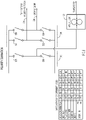
- FIG. 4 shows, as an aspect of AC TIG unit 200, a one switch module polarity elimination circuit and mechanical wire feeder disconnect switch in accordance with an example embodiment.
- the multi-process welding machine described herein includes AC TIG unit 200 ( FIGs. 1A and 1B ) that provides the desired AC voltage for an AC TIG process, when so selected.
- FIG. 4 shows how switches in a full bridge converter or switching module 415 may be configured to provide DC electrode positive or DC electrode negative modes of operation in AC TIG unit 200. That is, switches S41, S42, S43 and S44 can be configured ON or OFF to cause welding cable 201 to be positive or negative, and welding cable 202 to be the opposite polarity of welding cable 201. In one example, switches S42 and S43 operate ON for electrode positive output, and switches S41 and S44 operate ON for electrode negative output.
- a disconnect switch S45 is provided.
- Switch S45 may be a bidirectional electronic, mechanical, optical or electromechanical switch. Switch S45 is configured to automatically disconnect power to wire feeder 160 when the multi-process welding machine is, e.g., not configured for a MIG or Flux core welding process.
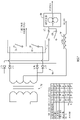
- FIG. 5 shows, as an aspect of AC TIG unit 200, a two switch module polarity elimination circuit in accordance with an example embodiment.
- a MIG torch (not shown) is connected with the multi-process welding machine 100 through only one switch in polarity elimination circuit 510, either S55 or S56, depending on the polarity selected.
- FIG. 5 also includes a table of the configuration of all switches S51, S52, S53, S54 (in full bridge converter or switching module 515), S55 and S56, depending on the type of welding process selected.
- FIG. 6 shows a circuit configured to reduce AC-DC loss using two power switches in accordance with an example embodiment.
- the components depicted in FIG. 6 can be thought of as replacing several components shown in FIGs. 1A and 1B . That is, FIG. 6 includes main transformer 635, which, instead of feeding an AC inverter board as shown in FIG. 1A , supplies power to diode network 640 comprising diodes D601, D602, D603 and D604. A center tap from main transformer 635 is connected to output inductor 637.
- FIG. 6 also includes switching module 615 that is configured to supply AC voltage or DC voltage. Also shown is a table of the configuration of switches S61, S62 and S63 depending on the type of welding process selected. By eliminating switches that are present in the configuration of FIGs. 1A and 1B power loss can be reduced.
- FIG. 7 shows another circuit configured to reduce AC-DC loss using two power switches in accordance with an example embodiment.
- the components depicted in FIG. 7 can be thought of as replacing several components shown in FIGs. 1A and 1B . That is, FIG. 7 includes main transformer 735, which, instead of feeding an AC inverter board as shown in FIG. 1B , supplies power to diode network 740 comprising diodes D701, D702, D703 and D704. A center tap from main transformer 735 is connected to output inductor 737.
- FIG. 7 also includes switching module 715 that is configured to supply AC voltage or DC voltage.
- FIG. 7 also includes a table of the configuration of switches S71, S72, S73 and S74 depending on the type of welding process selected. By eliminating switches that are present in the configuration of FIG. 1B , and further eliminating another switch between the wire feeder/torch supply, compared to the configuration in FIG. 6 , still more power loss can be reduced.
- FIG. 8 shows another circuit configured to reduce AC-DC loss using four switches in accordance with an example embodiment.
- the components depicted in FIG. 8 can be thought of as replacing several components shown in FIGs. 1A and 1B . That is, FIG. 8 includes main transformer 835 which, instead of feeding an AC inverter board as shown in FIG. 1 , supplies power to diode network 840 comprising diodes D801, D802, D803, and D804. A center tap from main transformer 835 is connected to output inductor 837.
- FIG. 8 also includes a table of the configuration of switches S81, S82, S83, S84 and S85 depending on the type of welding process selected. By eliminating switches that are present in the configuration of FIG. 1B , and further eliminating another switch between the wire feeder/torch supply, compared to the configuration in FIG. 6 , still more power loss can be reduced.
- FIG. 9 shows a circuit configured to select welding cable polarity in accordance with an example embodiment.
- the components depicted in FIG. 9 can be thought of as replacing several components shown in FIGs. 1A and 1B . That is, FIG. 9 includes main transformer 935 which, instead of feeding an AC inverter board as shown in FIG. 1B , supplies power to diode network 940 comprising diodes D901, D902, D903 and D904. A center tap from main transformer 935 is connected to output inductor 937.
- FIG. 9 also includes switching module 915 that is configured to select DC voltage polarity.
- FIG. 9 further shows analog switch control module 960 that is controllable via select switch 955 to select DC electrode positive (DCEP), or DC electrode negative (DCEN) for a given welding process. Once selected, switches S91, S92, S93 and S94 are automatically configured for the selected electrode polarity arrangement.
- DCEP DC electrode positive
- DCEN DC electrode negative
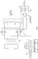
- FIGs. 10 and 11A -11C illustrate combining magnetics of the multi-process welding machine's main output inductor and high frequency start circuit's inductor in accordance with an example embodiment.
- Components depicted in FIG. 10 are similar to those shown in FIGs. 1A and 1B . That is, FIG. 10 includes main transformer 1035, which feeds an output rectifier 1040, which supplies power to switching module 1015, which can provide an AC output or be configured to supply a DC output depending on a selected configuration of the multi-process welding machine. A center tap from main transformer 1035 is connected to output inductor 1037. Also shown is HF start circuit 1030 that is connected to HF transformer 1070.
- An output inductor, like 1037, is designed to operate at high current with minimum inductance roll off by using relatively low permeability ferrite or magnetic material.
- an HF transformer, like 1070 is designed to handle high voltage per turn with relatively high permeability ferrite or magnetic material.
- the magnetics of output inductor 1037 and HF transformer 1070 are combined, as indicated by broken arrows 1081 and 1082.
- FIG. 11A shows an example arrangement of high and low permeability materials around which the output inductor 1037 and HF transformer 1070 coils can be wrapped.
- FIGs. 11A and 11C show high and low permeability materials arranged next to each other, and
- FIG. 11B shows the high and low permeability materials arranged concentrically.
- the magnetic materials can also be comingled into a homogenous structure, with each of the magnetic materials responding appropriately based on the frequency presented, number of turns wound, etc.
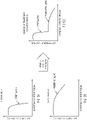
- FIGs. 12A-12C are graphs illustrating how the performance of high permeability material ( FIG. 12A ) and the performance of low permeability material ( FIG. 12B ) is combined to achieve an overall inductance performance curve ( FIG. 12C ) suitable for both an output inductor and HF transformer of a multi-process welding machine.
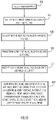
- FIG. 13 is a flow chart depicting a series of operations for operating a multi-process welding or cutting machine in accordance with an example embodiment.
- the methodology receives mains power.
- the mains power is rectified to generate a rectified voltage.
- the rectified voltage is converted to a first AC voltage.
- the first AC voltage is transformed to a second AC voltage.
- the second AC voltage is rectified to generate a DC welding current.
- the a multi-process welding or cutting machine outputs the DC welding current or an AC welding current according to input received via a graphical user interface, wherein the DC welding current, when output, passes through at least one electronic switching device configured to generate the AC welding current from the DC welding current.
- embodiments described herein provide a multi-process welding machine that provides an intuitive user interface to enable a user to select among different welding processes, and to select parameters for a given selected welding process.
- the multi-process welding machine also provides an arrangement by which a switching module or DC to AC converter of an AC TIG unit can be controlled to alternatively supply AC or DC welding voltages.
- the configuration of switches can be leveraged to automatically (or manually) control the polarity of the welding cables for different processes and to engage or disengage a wire feeder when, e.g., MIG welding is selected, or not selected, respectively.
- the ferrite or magnetic materials used for a main output inductor and an HF starting inductor can be combined.
Landscapes
- Engineering & Computer Science (AREA)
- Physics & Mathematics (AREA)
- Plasma & Fusion (AREA)
- Mechanical Engineering (AREA)
- Theoretical Computer Science (AREA)
- Arc Welding Control (AREA)
- Generation Of Surge Voltage And Current (AREA)
Claims (15)
- Un système de soudage portatif, qui comprend :un dispositif d'affichage configuré pour afficher une interface utilisateur graphique (150) ;une entrée d'alimentation configurée pour recevoir une alimentation secteur (101) ;et qui est en sus caractérisé par ce qui suit :un redresseur (103) connecté à l'entrée d'alimentation et configuré pour sortir une tension redressée ;un premier convertisseur en pont complet (130), en communication avec le redresseur (103), qui convertit la tension redressée en une première tension CA ;un tableau de commande (120), un organe de commande à modulation d'onde d'impulsion (PWM, Pulse Wave Modulated) (121), et un transformateur d'impulsion (125),où le tableau de commande fournit des premier et deuxième signaux à modulation d'onde d'impulsion (PWM) (PWMA, PWMB) générés par l'organe de commande PWM (121) au premier convertisseur en pont complet (130) et commande des commutateurs (SW1, SW2, SW3, SW4) du premier convertisseur en pont complet (130) par l'intermédiaire de signaux (PWM1, PWM2, PWM3, PWM4) générés par le transformateur d'impulsion (125) qui convertissent la tension redressée en cette première tension CA, et le tableau de commande fournit un troisième signal à modulation d'onde d'impulsion (PWM) (PWMC) ;un transformateur principal (135) configuré pour transformer la première tension CA en une deuxième tension CA ;un redresseur de sortie (140), en communication avec un secondaire du transformateur principal, configuré pour redresser la deuxième tension CA et sortir un courant de soudage CC ; etune unité CA (200), comprenant un deuxième convertisseur en pont complet (215) comprenant des commutateurs (SW7, SW8, SW9, SW10), configurée pour recevoir une sortie du redresseur de sortie (140), et sortir de manière sélective au moins un courant parmi le courant de soudage CC ou un courant de soudage CA suivant une entrée utilisateur reçue par le biais de l'interface utilisateur graphique (150),où l'unité CA (200) reçoit le troisième signal PWM (PWMC) provenant du tableau de commande (120) qui commande une fréquence et un facteur de marche du courant de soudage CA, etoù le courant de soudage CC, lorsqu'il est sorti, passe à travers au moins un des commutateurs électroniques (SW7, SW8, SW9, SW10) du deuxième convertisseur en pont complet (215).
- Le système de soudage portatif de la revendication 1, où le courant de soudage CC est configuré pour un procédé de soudage CC.
- Le système de soudage portatif de la revendication 2, où le procédé de soudage CC est un procédé de soudage MIG (Metal Inert Gas, sous gaz inerte avec électrode métallique).
- Le système de soudage portatif de la revendication 1, où le courant de soudage CA est configuré pour un procédé de soudage CA.
- Le système de soudage portatif de la revendication 4, où le procédé de soudage CA est un procédé de soudage TIG (Tungsten Inert Gas, sous gaz inerte avec électrode de tungstène) CA.
- Le système de soudage portatif de la revendication 1, où un dévidoir de fil (160) est automatiquement enclenché suivant une entrée reçue par le biais de l'interface utilisateur graphique (150).
- Le système de soudage portatif de la revendication 1, où une polarité de câbles de soudage (201, 202) du système de soudage portatif est automatiquement sélectionnée suivant une entrée reçue par le biais de l'interface utilisateur graphique (150).
- Le système de soudage portatif de la revendication 1, où une polarité de câbles de soudage (201, 202) du système de soudage portatif est sélectionnable par le biais d'un commutateur manuel.
- Le système de soudage portatif de la revendication 1, comprenant en sus :une inductance de sortie principale en communication avec le secondaire du transformateur principal ; etune inductance de départ haute fréquence connectée en série avec un câble de soudage.
- Une méthode qui est caractérisée par le fait :de recevoir une alimentation secteur (1302) ;de redresser l'alimentation secteur afin de générer une tension redressée (1304) ;de convertir par un premier convertisseur en pont complet (130) la tension redressée en une première tension CA (1306) sur la base de premier et de deuxième signaux à modulation d'onde d'impulsion (PWM) (PWMA, PWMB) fournis par un tableau de commande (120) ;de transformer la première tension CA en une deuxième tension CA (1308) ;de redresser le deuxième CA (1308) afin de générer un courant de soudage CC (1310) ; etde sortir de manière sélective, par l'intermédiaire d'une unité CA (200) comprenant un deuxième convertisseur en pont complet (215) ayant des commutateurs (SW7, SW8, SW9, SW10), le courant de soudage CC ou un courant de soudage CA suivant une entrée utilisateur reçue par le biais d'une interface utilisateur graphique (1312),où une fréquence et un facteur de marche du courant de soudage CA, lorsqu'il est sorti, est contrôlé par un signal PWM unique (PWMC) fourni par le tableau de commande (120) afin de convertir la tension redressée en cette première tension CA, etoù le courant de soudage CC, lorsqu'il est sorti, passe à travers au moins un des commutateurs (SW7, SW8, SW9, SW10) du deuxième convertisseur en pont complet (215) qui génère le courant de soudage CA à partir du courant de soudage CC.
- La méthode de la revendication 10, où le courant de soudage CC est configuré pour un procédé de soudage CC.
- La méthode de la revendication 11, où le procédé de soudage CC est un procédé de soudage MIG (Metal Inert Gas, sous gaz inerte avec électrode métallique).
- La méthode de la revendication 10, où le courant de soudage CA est configuré pour un procédé de soudage CA ; et facultativement, où le procédé de soudage CA est un procédé de soudage TIG (Tungsten Inert Gas, sous gaz inerte avec électrode de tungstène) CA.
- La méthode de la revendication 10, comprenant en sus le fait d'enclencher automatiquement un dévidoir de fil (160) suivant une entrée reçue par le biais de l'interface utilisateur graphique (150).
- La méthode de la revendication 10, comprenant en sus le fait de sélectionner automatiquement une polarité de câbles de soudage (201, 202) suivant une entrée reçue par le biais de l'interface utilisateur graphique (150).
Applications Claiming Priority (2)
| Application Number | Priority Date | Filing Date | Title |
|---|---|---|---|
| US201762577334P | 2017-10-26 | 2017-10-26 | |
| PCT/US2018/057275 WO2019084113A1 (fr) | 2017-10-26 | 2018-10-24 | Système de soudage portatif et procédé faisant appel à des techniques pour fournir un courant de soudage ca ou cc |
Publications (2)
| Publication Number | Publication Date |
|---|---|
| EP3727736A1 EP3727736A1 (fr) | 2020-10-28 |
| EP3727736B1 true EP3727736B1 (fr) | 2022-06-29 |
Family
ID=64453572
Family Applications (1)
| Application Number | Title | Priority Date | Filing Date |
|---|---|---|---|
| EP18807753.1A Not-in-force EP3727736B1 (fr) | 2017-10-26 | 2018-10-24 | Système de soudage portatif et procédé faisant appel à des techniques pour fournir un courant de soudage ca ou cc |
Country Status (4)
| Country | Link |
|---|---|
| US (1) | US11260465B2 (fr) |
| EP (1) | EP3727736B1 (fr) |
| ES (1) | ES2926349T3 (fr) |
| WO (1) | WO2019084113A1 (fr) |
Families Citing this family (4)
| Publication number | Priority date | Publication date | Assignee | Title |
|---|---|---|---|---|
| US10449615B2 (en) * | 2016-10-31 | 2019-10-22 | Illinois Tool Works Inc. | Hybrid welding modules |
| US10906117B2 (en) | 2018-01-30 | 2021-02-02 | Illinois Tool Works Inc. | System and method for providing welding type power on multiple outputs |
| WO2021114007A1 (fr) * | 2019-12-09 | 2021-06-17 | 上海威特力焊接设备制造股份有限公司 | Machine de soudage électrique multifonctionnelle |
| WO2023228089A1 (fr) * | 2022-05-23 | 2023-11-30 | Esab Ab | Source d'alimentation de soudage, système de soudage doté d'une telle source d'alimentation de soudage, étage de sélection cc-ca et procédé de commande d'une source d'alimentation de soudage |
Family Cites Families (37)
| Publication number | Priority date | Publication date | Assignee | Title |
|---|---|---|---|---|
| DE2749087A1 (de) | 1977-11-02 | 1979-05-03 | Lorch Schweisstech Gmbh | Schweissgeraet fuer mehrere schweissarten |
| US5025127A (en) | 1989-06-30 | 1991-06-18 | Gilliland Malcolm T | Electronic welding station with AC and reversible polarity DC outputs |
| US5406051A (en) * | 1993-04-29 | 1995-04-11 | Electric Power Research Institute | Welding machine with a high frequency converter |
| US6046664A (en) | 1998-03-05 | 2000-04-04 | Century Manufacturing Company | Welding power supply transformer apparatus and method |
| US6023037A (en) * | 1998-11-05 | 2000-02-08 | Lincoln Global, Inc. | Electric ARC welder and plasma cutter |
| CN1378895A (zh) | 2001-04-10 | 2002-11-13 | 卢子清 | 一体型可移动式交直流两用焊机 |
| US7183517B2 (en) * | 2003-11-26 | 2007-02-27 | Illinois Tool Works, Inc. | Portable welding-type apparatus with interchangeable energy storage device |
| US7297899B2 (en) | 2004-06-01 | 2007-11-20 | Illinois Tool Works Inc. | Operating parameter dependent variable output welding-type apparatus |
| US7952051B2 (en) | 2006-05-31 | 2011-05-31 | Illinois Tool Works Inc. | Electronic polarity reversing switch for a multi-process welding power source |
| US20080011727A1 (en) * | 2006-07-14 | 2008-01-17 | Lincoln Global, Inc. | Dual fillet welding methods and systems |
| US8946596B2 (en) | 2006-10-05 | 2015-02-03 | Lincoln Global, Inc. | Multiple welding using a single power source |
| US8785817B2 (en) | 2006-11-16 | 2014-07-22 | Illinois Tool Works Inc. | Method and apparatus for wireless remote control communication of a welder |
| US8653415B2 (en) | 2007-04-30 | 2014-02-18 | Illinois Tool Works Inc. | Engine-driven air compressor/generator load priority control system and method |
| US9108263B2 (en) | 2007-04-30 | 2015-08-18 | Illinois Tool Works Inc. | Welding power source with automatic variable high frequency |
| US8759714B2 (en) | 2007-07-06 | 2014-06-24 | Illinois Tool Works Inc. | Portable generator and battery charger verification control method and system |
| US8299398B2 (en) | 2007-08-10 | 2012-10-30 | Illinois Tool Works Inc. | Power supply configured to deliver AC welding-type power |
| US20090152251A1 (en) | 2007-12-18 | 2009-06-18 | Illinois Tool Works Inc. | Personalized interface for torch system and method |
| US8884189B2 (en) | 2009-01-16 | 2014-11-11 | Illinois Tool Works Inc. | Welding power to auxiliary power conversion system and method |
| US20110011842A1 (en) * | 2009-07-19 | 2011-01-20 | Thomas Jose P | Method and apparatus for receiving a universal 3 phase input voltage in a welding power source |
| CN201499029U (zh) | 2009-08-15 | 2010-06-02 | 凯捷利集团有限公司 | 交流发电直流电焊两用机 |
| US8957344B2 (en) | 2009-09-30 | 2015-02-17 | Illinois Tool Works Inc. | Welding system with power line communication |
| KR101086463B1 (ko) * | 2009-12-23 | 2011-11-25 | 주식회사 웰드라인 | 복합 용접기용 전원공급장치 및 그의 제어 방법 |
| IT1403120B1 (it) | 2010-09-13 | 2013-10-04 | Awelco Inc Production S P A | Macchina di saldatura con messaggi acustici. |
| CA2830995C (fr) | 2011-03-25 | 2019-05-14 | Illinois Tool Works Inc. | Systemes de soudage dotes de moyens permettant d'ajuster et d'afficher des plages de parametres configurant ces derniers et procede de configuration de tels parametres de soudage |
| US9789558B2 (en) | 2011-08-18 | 2017-10-17 | Illinois Tool Works Inc. | System and device operating using a welding power bus |
| US10259067B2 (en) | 2012-06-04 | 2019-04-16 | Illinois Tool Works Inc. | Remote polarity detection and control for welding process |
| US9114471B2 (en) | 2012-09-24 | 2015-08-25 | Lincoln Global, Inc. | Systems and methods providing low current regulation for AC arc welding processes |
| US9129817B2 (en) * | 2013-03-13 | 2015-09-08 | Intel Corporation | Magnetic core inductor (MCI) structures for integrated voltage regulators |
| US9623505B2 (en) | 2013-03-13 | 2017-04-18 | Lincoln Global, Inc. | Method and system of welding with a power supply having a single welding mode |
| WO2014192084A1 (fr) * | 2013-05-28 | 2014-12-04 | 三菱電機株式会社 | Convertisseur de puissance, dispositif de commande d'entraînement de moteur pourvu d'un convertisseur de puissance, compresseur et ventilateur pourvus d'un dispositif de commande d'entraînement de moteur et climatiseur pourvu d'un compresseur ou d'un ventilateur |
| US9238274B2 (en) | 2013-06-21 | 2016-01-19 | Lincoln Global, Inc. | System and method for hot wire TIG positioned heat control |
| US11027354B2 (en) | 2013-06-24 | 2021-06-08 | Illinois Tool Works Inc. | Modular power conversion system and method |
| US10773328B2 (en) | 2015-12-15 | 2020-09-15 | Illinois Tool Works Inc. | Welding system user interface having a color display for setting welding parameters |
| US10406624B2 (en) | 2016-03-07 | 2019-09-10 | Illinois Tool Works Inc. | Methods and apparatus to switch a weld power output |
| US10343230B2 (en) | 2016-03-31 | 2019-07-09 | Illinois Tool Works Inc. | Welding-type systems and user interfaces having a color display for displaying physical setup instructions |
| CN105817740B (zh) * | 2016-05-03 | 2018-05-01 | 深圳市佳士科技股份有限公司 | 焊接电源及交直流氩弧焊机 |
| US11027357B2 (en) * | 2017-07-28 | 2021-06-08 | Illinois Tool Works Inc. | Methods and apparatus to provide welding power |
-
2018
- 2018-10-24 EP EP18807753.1A patent/EP3727736B1/fr not_active Not-in-force
- 2018-10-24 US US16/169,226 patent/US11260465B2/en active Active
- 2018-10-24 WO PCT/US2018/057275 patent/WO2019084113A1/fr not_active Ceased
- 2018-10-24 ES ES18807753T patent/ES2926349T3/es active Active
Also Published As
| Publication number | Publication date |
|---|---|
| US20190126380A1 (en) | 2019-05-02 |
| ES2926349T3 (es) | 2022-10-25 |
| EP3727736A1 (fr) | 2020-10-28 |
| US11260465B2 (en) | 2022-03-01 |
| WO2019084113A1 (fr) | 2019-05-02 |
Similar Documents
| Publication | Publication Date | Title |
|---|---|---|
| US11673202B2 (en) | Welding system and method of welding | |
| US11260465B2 (en) | Portable AC-DC multi-process welding and cutting machine | |
| US8884189B2 (en) | Welding power to auxiliary power conversion system and method | |
| EP1981676B1 (fr) | Appareil de soudage utilisant le courant d'une batterie | |
| EP1993772B1 (fr) | Poste de soudure à courant alternatif haute intensité et methode de creation d'un arc electrique entre une electrode et une piece | |
| US8975558B2 (en) | Selector device for electric arc welder | |
| US8604384B2 (en) | System and methods for efficient provision of arc welding power source | |
| CA2841583C (fr) | Systeme et dispositif de fonctionnement d'un dispositif autre qu'un dispositif de soudage faisant appel a un bus de puissance de soudage | |
| KR20060043511A (ko) | 전기 아크 용접용 전원 | |
| EP3398249B1 (fr) | Alimentation électrique de soudage à circuits inverseurs entrelacés | |
| AU2020248378B2 (en) | Multi-process welding and cutting machine | |
| US10086466B2 (en) | Multivoltage welding apparatus | |
| EP3782758B1 (fr) | Procédé et appareil de fourniture de puissance de type soudage à convertisseur direct double | |
| KR101965827B1 (ko) | 스마트 제어 용접기 | |
| JP2006281257A (ja) | インバータ制御による消耗電極式のアーク溶接電源およびその制御方法 | |
| JP2002096166A (ja) | アーク溶接装置 | |
| JP2019030902A (ja) | 溶接電流の制御方法および溶接用電源装置 | |
| MXPA00009269A (en) | Cv background for welding |
Legal Events
| Date | Code | Title | Description |
|---|---|---|---|
| STAA | Information on the status of an ep patent application or granted ep patent |
Free format text: STATUS: UNKNOWN |
|
| STAA | Information on the status of an ep patent application or granted ep patent |
Free format text: STATUS: THE INTERNATIONAL PUBLICATION HAS BEEN MADE |
|
| PUAI | Public reference made under article 153(3) epc to a published international application that has entered the european phase |
Free format text: ORIGINAL CODE: 0009012 |
|
| STAA | Information on the status of an ep patent application or granted ep patent |
Free format text: STATUS: REQUEST FOR EXAMINATION WAS MADE |
|
| 17P | Request for examination filed |
Effective date: 20200803 |
|
| AK | Designated contracting states |
Kind code of ref document: A1 Designated state(s): AL AT BE BG CH CY CZ DE DK EE ES FI FR GB GR HR HU IE IS IT LI LT LU LV MC MK MT NL NO PL PT RO RS SE SI SK SM TR |
|
| AX | Request for extension of the european patent |
Extension state: BA ME |
|
| RIN1 | Information on inventor provided before grant (corrected) |
Inventor name: SANGHAVI, PRANAV Inventor name: GHARIB, AWAD Inventor name: MANAVALAN, ARIVUKKARASU Inventor name: CHEN, XIA Inventor name: YADAV, BINOD Inventor name: ANJANAPPA, MUNISWAMAPPA |
|
| RIN1 | Information on inventor provided before grant (corrected) |
Inventor name: YADAV, BINOD Inventor name: CHEN, XIA Inventor name: SANGHAVI, PRANAV Inventor name: ANJANAPPA, MUNISWAMAPPA Inventor name: MANAVALAN, ARIVUKKARASU Inventor name: GHARIB, AWAD |
|
| DAV | Request for validation of the european patent (deleted) | ||
| DAX | Request for extension of the european patent (deleted) | ||
| RIN1 | Information on inventor provided before grant (corrected) |
Inventor name: YADAV, BINOD Inventor name: SANGHAVI, PRANAV Inventor name: CHEN, XIA Inventor name: ANJANAPPA, MUNISWAMAPPA Inventor name: GHARIB, AWAD Inventor name: MANAVALAN, ARIVUKKARASU |
|
| GRAP | Despatch of communication of intention to grant a patent |
Free format text: ORIGINAL CODE: EPIDOSNIGR1 |
|
| STAA | Information on the status of an ep patent application or granted ep patent |
Free format text: STATUS: GRANT OF PATENT IS INTENDED |
|
| INTG | Intention to grant announced |
Effective date: 20210824 |
|
| GRAJ | Information related to disapproval of communication of intention to grant by the applicant or resumption of examination proceedings by the epo deleted |
Free format text: ORIGINAL CODE: EPIDOSDIGR1 |
|
| STAA | Information on the status of an ep patent application or granted ep patent |
Free format text: STATUS: REQUEST FOR EXAMINATION WAS MADE |
|
| INTC | Intention to grant announced (deleted) | ||
| GRAP | Despatch of communication of intention to grant a patent |
Free format text: ORIGINAL CODE: EPIDOSNIGR1 |
|
| STAA | Information on the status of an ep patent application or granted ep patent |
Free format text: STATUS: GRANT OF PATENT IS INTENDED |
|
| INTG | Intention to grant announced |
Effective date: 20220217 |
|
| GRAS | Grant fee paid |
Free format text: ORIGINAL CODE: EPIDOSNIGR3 |
|
| GRAA | (expected) grant |
Free format text: ORIGINAL CODE: 0009210 |
|
| STAA | Information on the status of an ep patent application or granted ep patent |
Free format text: STATUS: THE PATENT HAS BEEN GRANTED |
|
| AK | Designated contracting states |
Kind code of ref document: B1 Designated state(s): AL AT BE BG CH CY CZ DE DK EE ES FI FR GB GR HR HU IE IS IT LI LT LU LV MC MK MT NL NO PL PT RO RS SE SI SK SM TR |
|
| REG | Reference to a national code |
Ref country code: CH Ref legal event code: EP |
|
| REG | Reference to a national code |
Ref country code: AT Ref legal event code: REF Ref document number: 1500993 Country of ref document: AT Kind code of ref document: T Effective date: 20220715 |
|
| REG | Reference to a national code |
Ref country code: IE Ref legal event code: FG4D |
|
| REG | Reference to a national code |
Ref country code: DE Ref legal event code: R096 Ref document number: 602018037395 Country of ref document: DE |
|
| RAP4 | Party data changed (patent owner data changed or rights of a patent transferred) |
Owner name: THE ESAB GROUP INC. |
|
| REG | Reference to a national code |
Ref country code: LT Ref legal event code: MG9D |
|
| REG | Reference to a national code |
Ref country code: ES Ref legal event code: FG2A Ref document number: 2926349 Country of ref document: ES Kind code of ref document: T3 Effective date: 20221025 |
|
| PG25 | Lapsed in a contracting state [announced via postgrant information from national office to epo] |
Ref country code: SE Free format text: LAPSE BECAUSE OF FAILURE TO SUBMIT A TRANSLATION OF THE DESCRIPTION OR TO PAY THE FEE WITHIN THE PRESCRIBED TIME-LIMIT Effective date: 20220629 Ref country code: NO Free format text: LAPSE BECAUSE OF FAILURE TO SUBMIT A TRANSLATION OF THE DESCRIPTION OR TO PAY THE FEE WITHIN THE PRESCRIBED TIME-LIMIT Effective date: 20220929 Ref country code: LT Free format text: LAPSE BECAUSE OF FAILURE TO SUBMIT A TRANSLATION OF THE DESCRIPTION OR TO PAY THE FEE WITHIN THE PRESCRIBED TIME-LIMIT Effective date: 20220629 Ref country code: HR Free format text: LAPSE BECAUSE OF FAILURE TO SUBMIT A TRANSLATION OF THE DESCRIPTION OR TO PAY THE FEE WITHIN THE PRESCRIBED TIME-LIMIT Effective date: 20220629 Ref country code: GR Free format text: LAPSE BECAUSE OF FAILURE TO SUBMIT A TRANSLATION OF THE DESCRIPTION OR TO PAY THE FEE WITHIN THE PRESCRIBED TIME-LIMIT Effective date: 20220930 Ref country code: FI Free format text: LAPSE BECAUSE OF FAILURE TO SUBMIT A TRANSLATION OF THE DESCRIPTION OR TO PAY THE FEE WITHIN THE PRESCRIBED TIME-LIMIT Effective date: 20220629 Ref country code: BG Free format text: LAPSE BECAUSE OF FAILURE TO SUBMIT A TRANSLATION OF THE DESCRIPTION OR TO PAY THE FEE WITHIN THE PRESCRIBED TIME-LIMIT Effective date: 20220929 |
|
| REG | Reference to a national code |
Ref country code: NL Ref legal event code: MP Effective date: 20220629 |
|
| REG | Reference to a national code |
Ref country code: AT Ref legal event code: MK05 Ref document number: 1500993 Country of ref document: AT Kind code of ref document: T Effective date: 20220629 |
|
| PG25 | Lapsed in a contracting state [announced via postgrant information from national office to epo] |
Ref country code: RS Free format text: LAPSE BECAUSE OF FAILURE TO SUBMIT A TRANSLATION OF THE DESCRIPTION OR TO PAY THE FEE WITHIN THE PRESCRIBED TIME-LIMIT Effective date: 20220629 Ref country code: LV Free format text: LAPSE BECAUSE OF FAILURE TO SUBMIT A TRANSLATION OF THE DESCRIPTION OR TO PAY THE FEE WITHIN THE PRESCRIBED TIME-LIMIT Effective date: 20220629 |
|
| PG25 | Lapsed in a contracting state [announced via postgrant information from national office to epo] |
Ref country code: NL Free format text: LAPSE BECAUSE OF FAILURE TO SUBMIT A TRANSLATION OF THE DESCRIPTION OR TO PAY THE FEE WITHIN THE PRESCRIBED TIME-LIMIT Effective date: 20220629 |
|
| PG25 | Lapsed in a contracting state [announced via postgrant information from national office to epo] |
Ref country code: SM Free format text: LAPSE BECAUSE OF FAILURE TO SUBMIT A TRANSLATION OF THE DESCRIPTION OR TO PAY THE FEE WITHIN THE PRESCRIBED TIME-LIMIT Effective date: 20220629 Ref country code: SK Free format text: LAPSE BECAUSE OF FAILURE TO SUBMIT A TRANSLATION OF THE DESCRIPTION OR TO PAY THE FEE WITHIN THE PRESCRIBED TIME-LIMIT Effective date: 20220629 Ref country code: RO Free format text: LAPSE BECAUSE OF FAILURE TO SUBMIT A TRANSLATION OF THE DESCRIPTION OR TO PAY THE FEE WITHIN THE PRESCRIBED TIME-LIMIT Effective date: 20220629 Ref country code: PT Free format text: LAPSE BECAUSE OF FAILURE TO SUBMIT A TRANSLATION OF THE DESCRIPTION OR TO PAY THE FEE WITHIN THE PRESCRIBED TIME-LIMIT Effective date: 20221031 Ref country code: EE Free format text: LAPSE BECAUSE OF FAILURE TO SUBMIT A TRANSLATION OF THE DESCRIPTION OR TO PAY THE FEE WITHIN THE PRESCRIBED TIME-LIMIT Effective date: 20220629 Ref country code: AT Free format text: LAPSE BECAUSE OF FAILURE TO SUBMIT A TRANSLATION OF THE DESCRIPTION OR TO PAY THE FEE WITHIN THE PRESCRIBED TIME-LIMIT Effective date: 20220629 |
|
| PG25 | Lapsed in a contracting state [announced via postgrant information from national office to epo] |
Ref country code: PL Free format text: LAPSE BECAUSE OF FAILURE TO SUBMIT A TRANSLATION OF THE DESCRIPTION OR TO PAY THE FEE WITHIN THE PRESCRIBED TIME-LIMIT Effective date: 20220629 Ref country code: IS Free format text: LAPSE BECAUSE OF FAILURE TO SUBMIT A TRANSLATION OF THE DESCRIPTION OR TO PAY THE FEE WITHIN THE PRESCRIBED TIME-LIMIT Effective date: 20221029 |
|
| REG | Reference to a national code |
Ref country code: DE Ref legal event code: R097 Ref document number: 602018037395 Country of ref document: DE |
|
| PG25 | Lapsed in a contracting state [announced via postgrant information from national office to epo] |
Ref country code: AL Free format text: LAPSE BECAUSE OF FAILURE TO SUBMIT A TRANSLATION OF THE DESCRIPTION OR TO PAY THE FEE WITHIN THE PRESCRIBED TIME-LIMIT Effective date: 20220629 |
|
| PG25 | Lapsed in a contracting state [announced via postgrant information from national office to epo] |
Ref country code: DK Free format text: LAPSE BECAUSE OF FAILURE TO SUBMIT A TRANSLATION OF THE DESCRIPTION OR TO PAY THE FEE WITHIN THE PRESCRIBED TIME-LIMIT Effective date: 20220629 Ref country code: CZ Free format text: LAPSE BECAUSE OF FAILURE TO SUBMIT A TRANSLATION OF THE DESCRIPTION OR TO PAY THE FEE WITHIN THE PRESCRIBED TIME-LIMIT Effective date: 20220629 |
|
| PLBE | No opposition filed within time limit |
Free format text: ORIGINAL CODE: 0009261 |
|
| STAA | Information on the status of an ep patent application or granted ep patent |
Free format text: STATUS: NO OPPOSITION FILED WITHIN TIME LIMIT |
|
| PG25 | Lapsed in a contracting state [announced via postgrant information from national office to epo] |
Ref country code: MC Free format text: LAPSE BECAUSE OF FAILURE TO SUBMIT A TRANSLATION OF THE DESCRIPTION OR TO PAY THE FEE WITHIN THE PRESCRIBED TIME-LIMIT Effective date: 20220629 |
|
| REG | Reference to a national code |
Ref country code: CH Ref legal event code: PL |
|
| 26N | No opposition filed |
Effective date: 20230330 |
|
| REG | Reference to a national code |
Ref country code: BE Ref legal event code: MM Effective date: 20221031 |
|
| P01 | Opt-out of the competence of the unified patent court (upc) registered |
Effective date: 20230522 |
|
| PG25 | Lapsed in a contracting state [announced via postgrant information from national office to epo] |
Ref country code: LU Free format text: LAPSE BECAUSE OF NON-PAYMENT OF DUE FEES Effective date: 20221024 |
|
| PG25 | Lapsed in a contracting state [announced via postgrant information from national office to epo] |
Ref country code: LI Free format text: LAPSE BECAUSE OF NON-PAYMENT OF DUE FEES Effective date: 20221031 Ref country code: CH Free format text: LAPSE BECAUSE OF NON-PAYMENT OF DUE FEES Effective date: 20221031 |
|
| PG25 | Lapsed in a contracting state [announced via postgrant information from national office to epo] |
Ref country code: SI Free format text: LAPSE BECAUSE OF FAILURE TO SUBMIT A TRANSLATION OF THE DESCRIPTION OR TO PAY THE FEE WITHIN THE PRESCRIBED TIME-LIMIT Effective date: 20220629 |
|
| PG25 | Lapsed in a contracting state [announced via postgrant information from national office to epo] |
Ref country code: BE Free format text: LAPSE BECAUSE OF NON-PAYMENT OF DUE FEES Effective date: 20221031 |
|
| PG25 | Lapsed in a contracting state [announced via postgrant information from national office to epo] |
Ref country code: IE Free format text: LAPSE BECAUSE OF NON-PAYMENT OF DUE FEES Effective date: 20221024 |
|
| PGFP | Annual fee paid to national office [announced via postgrant information from national office to epo] |
Ref country code: GB Payment date: 20231027 Year of fee payment: 6 |
|
| PGFP | Annual fee paid to national office [announced via postgrant information from national office to epo] |
Ref country code: ES Payment date: 20231102 Year of fee payment: 6 |
|
| PGFP | Annual fee paid to national office [announced via postgrant information from national office to epo] |
Ref country code: IT Payment date: 20231023 Year of fee payment: 6 Ref country code: FR Payment date: 20231025 Year of fee payment: 6 Ref country code: DE Payment date: 20231027 Year of fee payment: 6 |
|
| PG25 | Lapsed in a contracting state [announced via postgrant information from national office to epo] |
Ref country code: CY Free format text: LAPSE BECAUSE OF FAILURE TO SUBMIT A TRANSLATION OF THE DESCRIPTION OR TO PAY THE FEE WITHIN THE PRESCRIBED TIME-LIMIT Effective date: 20220629 |
|
| PG25 | Lapsed in a contracting state [announced via postgrant information from national office to epo] |
Ref country code: MK Free format text: LAPSE BECAUSE OF FAILURE TO SUBMIT A TRANSLATION OF THE DESCRIPTION OR TO PAY THE FEE WITHIN THE PRESCRIBED TIME-LIMIT Effective date: 20220629 Ref country code: HU Free format text: LAPSE BECAUSE OF FAILURE TO SUBMIT A TRANSLATION OF THE DESCRIPTION OR TO PAY THE FEE WITHIN THE PRESCRIBED TIME-LIMIT; INVALID AB INITIO Effective date: 20181024 |
|
| PG25 | Lapsed in a contracting state [announced via postgrant information from national office to epo] |
Ref country code: MT Free format text: LAPSE BECAUSE OF FAILURE TO SUBMIT A TRANSLATION OF THE DESCRIPTION OR TO PAY THE FEE WITHIN THE PRESCRIBED TIME-LIMIT Effective date: 20220629 |
|
| PG25 | Lapsed in a contracting state [announced via postgrant information from national office to epo] |
Ref country code: BG Free format text: LAPSE BECAUSE OF FAILURE TO SUBMIT A TRANSLATION OF THE DESCRIPTION OR TO PAY THE FEE WITHIN THE PRESCRIBED TIME-LIMIT Effective date: 20220629 |
|
| PG25 | Lapsed in a contracting state [announced via postgrant information from national office to epo] |
Ref country code: BG Free format text: LAPSE BECAUSE OF FAILURE TO SUBMIT A TRANSLATION OF THE DESCRIPTION OR TO PAY THE FEE WITHIN THE PRESCRIBED TIME-LIMIT Effective date: 20220629 |
|
| REG | Reference to a national code |
Ref country code: DE Ref legal event code: R119 Ref document number: 602018037395 Country of ref document: DE |
|
| GBPC | Gb: european patent ceased through non-payment of renewal fee |
Effective date: 20241024 |
|
| PG25 | Lapsed in a contracting state [announced via postgrant information from national office to epo] |
Ref country code: DE Free format text: LAPSE BECAUSE OF NON-PAYMENT OF DUE FEES Effective date: 20250501 |
|
| PG25 | Lapsed in a contracting state [announced via postgrant information from national office to epo] |
Ref country code: GB Free format text: LAPSE BECAUSE OF NON-PAYMENT OF DUE FEES Effective date: 20241024 |
|
| PG25 | Lapsed in a contracting state [announced via postgrant information from national office to epo] |
Ref country code: FR Free format text: LAPSE BECAUSE OF NON-PAYMENT OF DUE FEES Effective date: 20241031 |
|
| PG25 | Lapsed in a contracting state [announced via postgrant information from national office to epo] |
Ref country code: IT Free format text: LAPSE BECAUSE OF NON-PAYMENT OF DUE FEES Effective date: 20241024 |
|
| REG | Reference to a national code |
Ref country code: ES Ref legal event code: FD2A Effective date: 20251128 |
|
| PG25 | Lapsed in a contracting state [announced via postgrant information from national office to epo] |
Ref country code: TR Free format text: LAPSE BECAUSE OF FAILURE TO SUBMIT A TRANSLATION OF THE DESCRIPTION OR TO PAY THE FEE WITHIN THE PRESCRIBED TIME-LIMIT Effective date: 20220629 |
|
| PG25 | Lapsed in a contracting state [announced via postgrant information from national office to epo] |
Ref country code: ES Free format text: LAPSE BECAUSE OF NON-PAYMENT OF DUE FEES Effective date: 20241025 |