EP0870664A2 - Procédé et dispositif pour le guidage des trains des roues des véhicules ferroviaires - Google Patents
Procédé et dispositif pour le guidage des trains des roues des véhicules ferroviaires Download PDFInfo
- Publication number
- EP0870664A2 EP0870664A2 EP98100507A EP98100507A EP0870664A2 EP 0870664 A2 EP0870664 A2 EP 0870664A2 EP 98100507 A EP98100507 A EP 98100507A EP 98100507 A EP98100507 A EP 98100507A EP 0870664 A2 EP0870664 A2 EP 0870664A2
- Authority
- EP
- European Patent Office
- Prior art keywords
- guide frame
- wheelset
- static
- angle
- control
- Prior art date
- Legal status (The legal status is an assumption and is not a legal conclusion. Google has not performed a legal analysis and makes no representation as to the accuracy of the status listed.)
- Granted
Links
- 238000000034 method Methods 0.000 title claims description 7
- 230000003068 static effect Effects 0.000 claims abstract description 4
- 238000011156 evaluation Methods 0.000 claims description 3
- 230000000694 effects Effects 0.000 claims description 2
- 230000001419 dependent effect Effects 0.000 abstract 1
- 239000012530 fluid Substances 0.000 description 8
- 230000008859 change Effects 0.000 description 4
- 238000013461 design Methods 0.000 description 3
- 230000008878 coupling Effects 0.000 description 2
- 238000010168 coupling process Methods 0.000 description 2
- 238000005859 coupling reaction Methods 0.000 description 2
- 230000009471 action Effects 0.000 description 1
- 238000013459 approach Methods 0.000 description 1
- 238000013016 damping Methods 0.000 description 1
- 238000011161 development Methods 0.000 description 1
- 230000005284 excitation Effects 0.000 description 1
- 230000006872 improvement Effects 0.000 description 1
- 230000003993 interaction Effects 0.000 description 1
- 230000007257 malfunction Effects 0.000 description 1
- 230000009467 reduction Effects 0.000 description 1
- 230000007704 transition Effects 0.000 description 1
Images

Classifications
-
- B—PERFORMING OPERATIONS; TRANSPORTING
- B61—RAILWAYS
- B61F—RAIL VEHICLE SUSPENSIONS, e.g. UNDERFRAMES, BOGIES OR ARRANGEMENTS OF WHEEL AXLES; RAIL VEHICLES FOR USE ON TRACKS OF DIFFERENT WIDTH; PREVENTING DERAILING OF RAIL VEHICLES; WHEEL GUARDS, OBSTRUCTION REMOVERS OR THE LIKE FOR RAIL VEHICLES
- B61F5/00—Constructional details of bogies; Connections between bogies and vehicle underframes; Arrangements or devices for adjusting or allowing self-adjustment of wheel axles or bogies when rounding curves
- B61F5/38—Arrangements or devices for adjusting or allowing self- adjustment of wheel axles or bogies when rounding curves, e.g. sliding axles, swinging axles
- B61F5/44—Adjustment controlled by movements of vehicle body
-
- B—PERFORMING OPERATIONS; TRANSPORTING
- B61—RAILWAYS
- B61F—RAIL VEHICLE SUSPENSIONS, e.g. UNDERFRAMES, BOGIES OR ARRANGEMENTS OF WHEEL AXLES; RAIL VEHICLES FOR USE ON TRACKS OF DIFFERENT WIDTH; PREVENTING DERAILING OF RAIL VEHICLES; WHEEL GUARDS, OBSTRUCTION REMOVERS OR THE LIKE FOR RAIL VEHICLES
- B61F5/00—Constructional details of bogies; Connections between bogies and vehicle underframes; Arrangements or devices for adjusting or allowing self-adjustment of wheel axles or bogies when rounding curves
- B61F5/26—Mounting or securing axle-boxes in vehicle or bogie underframes
- B61F5/30—Axle-boxes mounted for movement under spring control in vehicle or bogie underframes
- B61F5/32—Guides, e.g. plates, for axle-boxes
- B61F5/325—The guiding device including swinging arms or the like to ensure the parallelism of the axles
-
- B—PERFORMING OPERATIONS; TRANSPORTING
- B61—RAILWAYS
- B61F—RAIL VEHICLE SUSPENSIONS, e.g. UNDERFRAMES, BOGIES OR ARRANGEMENTS OF WHEEL AXLES; RAIL VEHICLES FOR USE ON TRACKS OF DIFFERENT WIDTH; PREVENTING DERAILING OF RAIL VEHICLES; WHEEL GUARDS, OBSTRUCTION REMOVERS OR THE LIKE FOR RAIL VEHICLES
- B61F5/00—Constructional details of bogies; Connections between bogies and vehicle underframes; Arrangements or devices for adjusting or allowing self-adjustment of wheel axles or bogies when rounding curves
- B61F5/38—Arrangements or devices for adjusting or allowing self- adjustment of wheel axles or bogies when rounding curves, e.g. sliding axles, swinging axles
- B61F5/386—Arrangements or devices for adjusting or allowing self- adjustment of wheel axles or bogies when rounding curves, e.g. sliding axles, swinging axles fluid actuated
Definitions
- the invention relates to a method and associated devices for wheel set guidance of rail vehicles, in particular to ensure the running stability of the vehicles in the High speed traffic where the wheelsets are in guide frames aligned and defined at right angles to each other stiffly and immovably statically guided as well as those at those to improve the arc run quasi-static radial Wheelset positions are specified.
- bogies with rigid axle guidance have narrow Arches a higher driving resistance as well as an above average Wear of the wheel profiles.
- the in-phase wheel set sine run first to unstable running behavior of the chassis.
- the wheelsets perform a combined transverse and turning movement around their respective Vertical axis.
- the opposite phase wheelset which at occur at the same frequency as the in-phase wheelset run can, on the other hand, is damped significantly higher.
- By the opposite Coupling of the wheel sets becomes their deflection in the same direction prevents and the running behavior both in the straight track improved in the bow as well.
- the disadvantage here is that with this solution only a limited increase in critical speeds is possible for high speed traffic not enough.
- undercarriages are known in which for improvement the wheel sets in the curve within the guide frame can be set quasi-statically radially, with direct acting on the elastic frame-side wishbone bearings external forces force the wheel sets to rotate radially (DE 42 40 098) or cylinder lever systems the position of the Determine the wheel set so that there is a change in direction and curvature the curve sets predetermined wheel set turning angle (DE 30 04 082).
- DE 42 40 098 direct acting on the elastic frame-side wishbone bearings external forces force the wheel sets to rotate radially
- cylinder lever systems the position of the Determine the wheel set so that there is a change in direction and curvature the curve sets predetermined wheel set turning angle
- the invention specified in the patent claim is the problem based on avoiding the disadvantages described above
- Methods and devices for controlling undercarriages create a stable wheelset run in all driving conditions and by decoupling the power between the chassis and the body enable high running quality.
- the measure of superimposing the predefined static or quasi-static wheel set position with a variable setting angle ⁇ St which is caused by active forces within the chassis between the wheel set and the guide frame, changes the path curve of the wheel set determined by the contact geometry, and deviations in the track curve and changes in the contact geometry are controlled without significantly affecting the basic rigidity of the guide.
- the frequency and decay curve of the deflection amplitude can be adjusted to a stable running behavior in the entire speed range with low power.
- the method can be carried out redundantly without significant additional effort. It is no longer necessary to prevent rotation between the undercarriage and the body, but it can also be used as a fallback level.
- the setting angle ⁇ St is small compared to the quasi-static turning angle of wheel sets with radial adjustment in small and medium-sized bends and can also be superimposed on this if the required overall rigidity of the axle guide is given. Its direction, size and frequency is determined from the control variables mentioned in the characterizing part of claim 2 and by the driving speed.
- the advantages of the solution according to the invention are in particular in that the stability and quality of vehicle running while maintaining the proven wheelset design theoretically unlimited up to the maximum speed range without loss of security is guaranteed.
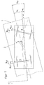
- the car body 1 of a rail vehicle can be seen, which is rotated relative to the track axis x by the angle ⁇ K and is shifted relative to the guide frame 2 by the dimension w.
- the guide frame 2 is itself turned out by an angle ⁇ D with respect to the track axis x.
- the turn ⁇ AD of the guide frame 2 to the body 1 is the difference between the two turns.
- the wheel sets 3, 3 ' which are oriented perpendicularly to the longitudinal axis of the guide frame 2 without external force action, are each turned out by an active control system by the variable angle ⁇ St3,3' .
- the turning angle ⁇ AR can be used, which is the difference between the turning of the wheel sets 3, 3 'to the track and that of the car body 1 to the track.
- the wheel sets 3, 3 ' are already set radially radially by external forces with the angles - ⁇ B3 and ⁇ B3 and are additionally turned out by an active control by the variable angles - ⁇ St3' and - ⁇ St3 .
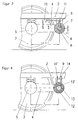
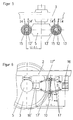
- 3 to 6 show possible design variants of the active control of the setting angle ⁇ St for influencing the wheel set shaft run.
- the device-technical design for determining the control variable for the setting angle ⁇ St (measuring sensor for ⁇ AD or / and ⁇ AR , evaluation unit) , which can be realized with known technical solutions.
- FIG. 3 shows a device with which a wheel set 3 held statically or guasistatically in the guide frame 2 by a swing arm 4 can be acted upon with the variable setting angle ⁇ St.
- the guide frame 2 is spring-supported on the axle bearing housing 5 of the wheel set 3.
- the axle bearing housing 5 has a swing arm 4 with an elastic bushing 6, which is mounted in the swing arm bearing 9 via eccentric 7 and eccentric shaft 8.
- An adjusting device 10 for example a hydraulic cylinder, changes the connection length L of the swing arm 4 with respect to the guide frame 2 by ⁇ ⁇ L via the eccentric lever 11.
- Fig. 4 shows a further device which generates the setting angle ⁇ St by using a two-chamber fluid bushing 12 in the swing arm 4.
- the guide frame 2 is supported on the axle bearing housing 5.
- the axle bearing housing 5 also has the swing arm 4, but equipped with an elastic two-chamber fluid bushing 12, the chambers 13, 13 'of which can be acted upon alternately by the connections 14, 14' and thus a change in the connection length L of the swing arm 4 compared to that Effect the guide frame 2 by the amount ⁇ ⁇ L.
- Fig. 5 varies Fig. 4 such that instead of a swing arm 4th Guide spindles 15 with two-chamber fluid bushings 12, 12 'for Wheelset guidance can be used.
- the guide frame 2 again suspended on the axle bearing housing 5 of the wheel set 3 supported.
- FIG. 6 shows a device which has the possibility of generating the setting angle ⁇ St with a double spring leaf wheel control arm 17.
- the guide frame 3 is spring-supported on the axle bearing housing 5 of the wheel set 3.
- the guide frame 2 and the axle bearing housing 5 have bearings 16, 16 'which are connected to one another with the spring leaf wheel set arms 17', 17 '' which are cranked in opposite directions. They are connected in their cranked middle area by an adjusting device 10 which, when actuated, changes the distance A of the links 17 ', 17''in this area by ⁇ A and thus causes a change in length L by ⁇ ⁇ L.
- the current angular position ⁇ AD of the guide frame 2 to the body 1 and / or the position ⁇ AR of the wheel sets 3, 3 'to the body 1 is determined with transducers and an evaluation unit and at the same time the wheel set sine run is analyzed as a measure of the stability.
- a signal generator is activated which over control variable generator and control elements (Fig. 3 to 6) between the guide frame 2 and axle bearing housing 5 overlaps each wheel set position with an adjustment angle ⁇ St so that an extension of the Sinus is caused.
- a rectified sinusoidal movement of the wheel sets 3, 3 ' is shown in a straight track or large arches, which is also superimposed by rectified adjusting angle - ⁇ St so that the wheel set is stretched.
- An opposite sinus movement can also be controlled in this sense. It is advisable, however, to actively prevent the opposite sinus movement in the development phase and to force the system to perform a sinus movement in the same direction.
- the wheel sets 3, 3 'to the guide frame 2 are set quasi-radially arc. At high driving speeds above the compensating speed, these positions are overlaid by rectified setting angles - ⁇ St , which minimize the approach angles outside the arc and avoid instabilities. At low speeds below the compensation speed, a negative setting angle ⁇ St is still superimposed on the wheel set 3 and a positive setting angle am St on the wheel set 3 '.
Landscapes
- Engineering & Computer Science (AREA)
- Mechanical Engineering (AREA)
- Platform Screen Doors And Railroad Systems (AREA)
- Vehicle Body Suspensions (AREA)
- Control Of Position, Course, Altitude, Or Attitude Of Moving Bodies (AREA)
- Escalators And Moving Walkways (AREA)
- Steering Controls (AREA)
Applications Claiming Priority (2)
| Application Number | Priority Date | Filing Date | Title |
|---|---|---|---|
| DE19715148A DE19715148A1 (de) | 1997-04-11 | 1997-04-11 | Verfahren und Einrichtung zur Radsatzführung von Schienenfahrzeugen |
| DE19715148 | 1997-04-11 |
Publications (3)
| Publication Number | Publication Date |
|---|---|
| EP0870664A2 true EP0870664A2 (fr) | 1998-10-14 |
| EP0870664A3 EP0870664A3 (fr) | 2000-03-01 |
| EP0870664B1 EP0870664B1 (fr) | 2008-04-02 |
Family
ID=7826224
Family Applications (1)
| Application Number | Title | Priority Date | Filing Date |
|---|---|---|---|
| EP98100507A Expired - Lifetime EP0870664B1 (fr) | 1997-04-11 | 1998-01-14 | Procédé et dispositif pour le guidage des trains de roues des véhicules ferroviaires |
Country Status (6)
| Country | Link |
|---|---|
| EP (1) | EP0870664B1 (fr) |
| AT (1) | ATE391063T1 (fr) |
| CZ (1) | CZ289238B6 (fr) |
| DE (2) | DE19715148A1 (fr) |
| ES (1) | ES2306463T3 (fr) |
| PL (1) | PL186906B1 (fr) |
Cited By (12)
| Publication number | Priority date | Publication date | Assignee | Title |
|---|---|---|---|---|
| WO2001015954A1 (fr) * | 1999-08-31 | 2001-03-08 | Construcciones Y Auxiliar De Ferrocarriles, S.A. | Dispositif de guidage des axes d'un vehicule ferroviaire |
| GB2364678A (en) * | 2000-07-13 | 2002-02-06 | Stephen Carl Henderson | Steering of wheels on a bogie |
| EP1209058A3 (fr) * | 2000-11-21 | 2003-01-15 | Integral Verkehrstechnik Aktiengesellschaft | Dispositif d'orientation pour bogies avec essieu unique |
| WO2003010039A3 (fr) * | 2001-07-27 | 2003-11-20 | Bombardier Transp Gmbh | Procede et dispositif de commande radiale active de paires de roues ou de jeux de roues de vehicules |
| WO2008155185A1 (fr) * | 2007-06-19 | 2008-12-24 | Siemens Transportation Systems Gmbh & Co. Kg | Procédé pour minimiser les endommagements des surfaces de roulement et l'usure des profils des roues d'un véhicule ferroviaire |
| WO2016008731A1 (fr) * | 2014-07-18 | 2016-01-21 | Siemens Aktiengesellschaft | Train de roulement d'un véhicule ferroviaire |
| EP3241716A1 (fr) * | 2016-04-28 | 2017-11-08 | Siemens AG Österreich | Bogie de véhicule ferroviaire |
| WO2018153436A1 (fr) * | 2017-02-21 | 2018-08-30 | Siemens Ag Österreich | Châssis pour véhicules sur rails |
| DE102017003307A1 (de) | 2017-04-05 | 2018-10-11 | Hartmut Jörck | Eisenbahntransportsystem für den kombinierten Verkehr |
| CN114620087A (zh) * | 2020-12-14 | 2022-06-14 | 西屋铁路有限公司 | 牵引杆组件 |
| WO2022248377A1 (fr) | 2021-05-27 | 2022-12-01 | Siemens Mobility Austria Gmbh | Bogie pour un véhicule ferroviaire |
| EP4223611A1 (fr) * | 2022-02-02 | 2023-08-09 | Siemens Mobility Austria GmbH | Dispositif de couplage fluidique et châssis |
Families Citing this family (5)
| Publication number | Priority date | Publication date | Assignee | Title |
|---|---|---|---|---|
| CZ2014572A3 (cs) * | 2014-08-25 | 2016-04-27 | VĂšKV a.s. | Systém měření úhlu náběhu dvojkolí kolejového vozidla v koleji |
| AT518973B1 (de) | 2016-03-17 | 2021-06-15 | Siemens Mobility Austria Gmbh | Fahrwerk für ein Schienenfahrzeug |
| WO2017202449A1 (fr) | 2016-05-24 | 2017-11-30 | Siemens Ag Österreich | Train roulant pour un véhicule ferroviaire |
| AT519394B1 (de) | 2016-11-24 | 2023-01-15 | Siemens Mobility Austria Gmbh | Radsteuerungsanordnung für ein Fahrwerk |
| AT525480A1 (de) | 2021-09-23 | 2023-04-15 | Siemens Mobility Austria Gmbh | Versorgungsanschluss für eine Radlenkvorrichtung, Radlenkvorrichtung für ein Fahrwerk und Fahrwerk |
Citations (3)
| Publication number | Priority date | Publication date | Assignee | Title |
|---|---|---|---|---|
| DE3004082A1 (de) | 1980-01-30 | 1981-08-06 | Schweizerische Lokomotiv- Und Maschinenfabrik, Winterthur | Einrichtung zur steuerung der schwenkbewegung eines schienenfahrzeuges in einer kurve |
| DE3123858A1 (de) | 1981-06-16 | 1982-12-30 | Fried. Krupp Gmbh, 4300 Essen | Laufwerk fuer ein schienenfahrzeug |
| DE4240098A1 (de) | 1992-11-28 | 1994-06-01 | Krupp Verkehrstechnik Gmbh | Fahrwerk für Schienenfahrzeuge |
Family Cites Families (5)
| Publication number | Priority date | Publication date | Assignee | Title |
|---|---|---|---|---|
| DE3334161A1 (de) * | 1983-09-21 | 1985-04-04 | Knorr-Bremse GmbH, 8000 München | Steuervorrichtung fuer fahrzeuge, insbesondere schienenfahrzeuge |
| FR2624081A1 (fr) * | 1987-12-03 | 1989-06-09 | Alsthom | Vehicule a essieux orientables |
| AT407140B (de) * | 1993-11-26 | 2000-12-27 | Integral Verkehrstechnik Ag | Einrichtung zur steuerung eines rades, insbesondere eines radsatzes eines schienenfahrzeuges |
| CH690032A5 (fr) * | 1994-07-13 | 2000-03-31 | Vevey Technologies Sa | Procédé de réglage de l'orientation des dispositifs de roulement à roues orientables d'un ensemble roulant sur rail et ensemble roulant utilisant ce procédé. |
| EP0759390B1 (fr) * | 1995-08-23 | 2000-03-08 | SLM Schweizerische Lokomotiv- und Maschinenfabrik AG | Train de roues pour un véhicule ferroviaire avec de jeux de roues ajustables et véhicule ferroviaire avec un tel train de roues |
-
1997
- 1997-04-11 DE DE19715148A patent/DE19715148A1/de not_active Withdrawn
-
1998
- 1998-01-14 AT AT98100507T patent/ATE391063T1/de active
- 1998-01-14 DE DE59814200T patent/DE59814200D1/de not_active Expired - Lifetime
- 1998-01-14 EP EP98100507A patent/EP0870664B1/fr not_active Expired - Lifetime
- 1998-01-14 ES ES98100507T patent/ES2306463T3/es not_active Expired - Lifetime
- 1998-02-26 PL PL98325047A patent/PL186906B1/pl not_active IP Right Cessation
- 1998-03-11 CZ CZ1998729A patent/CZ289238B6/cs not_active IP Right Cessation
Patent Citations (3)
| Publication number | Priority date | Publication date | Assignee | Title |
|---|---|---|---|---|
| DE3004082A1 (de) | 1980-01-30 | 1981-08-06 | Schweizerische Lokomotiv- Und Maschinenfabrik, Winterthur | Einrichtung zur steuerung der schwenkbewegung eines schienenfahrzeuges in einer kurve |
| DE3123858A1 (de) | 1981-06-16 | 1982-12-30 | Fried. Krupp Gmbh, 4300 Essen | Laufwerk fuer ein schienenfahrzeug |
| DE4240098A1 (de) | 1992-11-28 | 1994-06-01 | Krupp Verkehrstechnik Gmbh | Fahrwerk für Schienenfahrzeuge |
Non-Patent Citations (2)
| Title |
|---|
| GDS 300, EISENBAHNINGENIEUR, October 1994 (1994-10-01), pages 722 |
| TGV, ELEKTRISCHE BAHNEN 90, May 1992 (1992-05-01), pages 176 - 179 |
Cited By (25)
| Publication number | Priority date | Publication date | Assignee | Title |
|---|---|---|---|---|
| WO2001015954A1 (fr) * | 1999-08-31 | 2001-03-08 | Construcciones Y Auxiliar De Ferrocarriles, S.A. | Dispositif de guidage des axes d'un vehicule ferroviaire |
| GB2364678A (en) * | 2000-07-13 | 2002-02-06 | Stephen Carl Henderson | Steering of wheels on a bogie |
| GB2364678B (en) * | 2000-07-13 | 2004-05-12 | Stephen Carl Henderson | Improved steered vehicle |
| US6932173B2 (en) | 2000-07-13 | 2005-08-23 | Stephen Carl Henderson | Steered vehicle |
| EP1209058A3 (fr) * | 2000-11-21 | 2003-01-15 | Integral Verkehrstechnik Aktiengesellschaft | Dispositif d'orientation pour bogies avec essieu unique |
| WO2003010039A3 (fr) * | 2001-07-27 | 2003-11-20 | Bombardier Transp Gmbh | Procede et dispositif de commande radiale active de paires de roues ou de jeux de roues de vehicules |
| RU2283254C2 (ru) * | 2001-07-27 | 2006-09-10 | Бомбардир Транспортацион Гмбх | Способ и устройство для активного управления радиальной установкой колесных пар или колесных скатов транспортных средств |
| US7458324B2 (en) | 2001-07-27 | 2008-12-02 | Bombardier Transportation | Method and device for active radial control of wheel pairs or wheel sets on vehicles |
| KR100916439B1 (ko) * | 2001-07-27 | 2009-09-07 | 봄바디어 트랜스포테이션 게엠베하 | 차량의 휠 쌍 또는 휠 세트의 능동 레이디얼 제어 방법 및장치 |
| WO2008155185A1 (fr) * | 2007-06-19 | 2008-12-24 | Siemens Transportation Systems Gmbh & Co. Kg | Procédé pour minimiser les endommagements des surfaces de roulement et l'usure des profils des roues d'un véhicule ferroviaire |
| CN101821146B (zh) * | 2007-06-19 | 2013-02-06 | 奥地利西门子公司 | 用于将轨道车辆的轮子的工作面损伤和轮廓磨损降低到最低限度的方法 |
| US8485109B2 (en) | 2007-06-19 | 2013-07-16 | Siemens Ag Österreich | Method for minimizing tread damage and profile wear of wheels of a railway vehicle |
| WO2016008731A1 (fr) * | 2014-07-18 | 2016-01-21 | Siemens Aktiengesellschaft | Train de roulement d'un véhicule ferroviaire |
| US10300932B2 (en) | 2014-07-18 | 2019-05-28 | Siemens Mobility GmbH | Chassis for a rail vehicle |
| EP3241716A1 (fr) * | 2016-04-28 | 2017-11-08 | Siemens AG Österreich | Bogie de véhicule ferroviaire |
| AT518699A1 (de) * | 2016-04-28 | 2017-12-15 | Siemens Ag Oesterreich | Fahrwerk für ein Schienenfahrzeug |
| WO2018153436A1 (fr) * | 2017-02-21 | 2018-08-30 | Siemens Ag Österreich | Châssis pour véhicules sur rails |
| US11529976B2 (en) | 2017-02-21 | 2022-12-20 | Siemens Mobility Austria Gmbh | Chassis for rail vehicles |
| DE102017003307A1 (de) | 2017-04-05 | 2018-10-11 | Hartmut Jörck | Eisenbahntransportsystem für den kombinierten Verkehr |
| CN114620087A (zh) * | 2020-12-14 | 2022-06-14 | 西屋铁路有限公司 | 牵引杆组件 |
| EP4011743A1 (fr) * | 2020-12-14 | 2022-06-15 | Wabtec Rail Limited | Ensemble tige de traction |
| US20220185344A1 (en) * | 2020-12-14 | 2022-06-16 | Wabtec Rail Limited | Traction rod assembly |
| US12415553B2 (en) * | 2020-12-14 | 2025-09-16 | Wabtec Uk Limited | Traction rod assembly |
| WO2022248377A1 (fr) | 2021-05-27 | 2022-12-01 | Siemens Mobility Austria Gmbh | Bogie pour un véhicule ferroviaire |
| EP4223611A1 (fr) * | 2022-02-02 | 2023-08-09 | Siemens Mobility Austria GmbH | Dispositif de couplage fluidique et châssis |
Also Published As
| Publication number | Publication date |
|---|---|
| DE19715148A1 (de) | 1998-10-15 |
| ES2306463T3 (es) | 2008-11-01 |
| EP0870664B1 (fr) | 2008-04-02 |
| PL186906B1 (pl) | 2004-03-31 |
| PL325047A1 (en) | 1998-10-12 |
| CZ72998A3 (cs) | 1998-10-14 |
| CZ289238B6 (cs) | 2001-12-12 |
| DE59814200D1 (de) | 2008-05-15 |
| EP0870664A3 (fr) | 2000-03-01 |
| ATE391063T1 (de) | 2008-04-15 |
Similar Documents
| Publication | Publication Date | Title |
|---|---|---|
| EP0870664B1 (fr) | Procédé et dispositif pour le guidage des trains de roues des véhicules ferroviaires | |
| EP0303007B1 (fr) | Train de roulement pour véhicule ferroviaire | |
| EP1003660B1 (fr) | Bogie pour un vehicule sur rails | |
| EP1412240B1 (fr) | Procede et dispositif de commande radiale active de paires de roues ou de jeux de roues de vehicules | |
| DE69521680T2 (de) | Ein Schienenfahrzeug mit Wagenkasten mit einstellbarer Neigung | |
| EP0736439B1 (fr) | Train de roulement pour véhicules ferroviaires | |
| DE3711907A1 (de) | Gleisbogenabhaengige wagenkastenneigungssteuerung fuer luftfeder-drehgestelle | |
| DE19712752C2 (de) | Schienenfahrzeug mit Knickgelenk und Verfahren zur Steuerung des Knickwinkels | |
| CH699589A2 (de) | Güterwagendrehgestell. | |
| EP3239015B1 (fr) | Guidage latéral du boudin à contrôle de force pour un véhicule sur rail | |
| DE3510454A1 (de) | Drehgestell und schienenfahrzeug sowie verfahren zum notabstuetzen | |
| EP0388999A2 (fr) | Dispositif mécanique pour supporter des véhicules ferroviaires | |
| EP0659626B1 (fr) | Train de roulement individuel pour véhicules ferroviaires | |
| DE4309324C1 (de) | Einachsfahrwerk für Schienenfahrzeuge | |
| EP1193154A1 (fr) | Méthode et dispositif pour stabiliser les oscillations de lacet d' essieux ferroviaires | |
| DE4426166A1 (de) | Verfahren zur Querstabilisierung von Schienenfahrzeugen mit gleisbogenabhängiger Wagenkastensteuerung | |
| EP4308431B1 (fr) | Bogie pour un véhicule ferroviaire | |
| EP0901424B1 (fr) | Procede permettant d'incliner et/ou de positionner un pantographe monte sur une caisse de wagon | |
| DE29613586U1 (de) | Niederflurdrehgestell | |
| EP0760322A2 (fr) | Arrangement de ressort pour trains de roulement des véhicules ferroviaires et pour points d'accouplement des trains articulés | |
| DE19542369A1 (de) | Pendelsystem für Schienenfahrzeuge | |
| AT505871B1 (de) | Fünfachsiges laufwerk für ein schienenfahrzeug | |
| DE2414228A1 (de) | Raederfahrwerk fuer schienenfahrzeuge mit magnetischer oder elektrodynamischer beeinflussung der fuehrung im gleis | |
| DE9214101U1 (de) | Aufhängung zur Führung der in einem Drehgestell von Schienenfahrzeugen angeordneten Antriebsaggregate | |
| DE29720120U1 (de) | Fahrwerk für Schienenfahrzeuge |
Legal Events
| Date | Code | Title | Description |
|---|---|---|---|
| PUAI | Public reference made under article 153(3) epc to a published international application that has entered the european phase |
Free format text: ORIGINAL CODE: 0009012 |
|
| AK | Designated contracting states |
Kind code of ref document: A2 Designated state(s): AT BE CH DE ES FR GB IT LI SE |
|
| AX | Request for extension of the european patent |
Free format text: AL;LT;LV;MK;RO;SI |
|
| PUAL | Search report despatched |
Free format text: ORIGINAL CODE: 0009013 |
|
| RTI1 | Title (correction) |
Free format text: PROCEDURE AND DEVICE FOR GUIDING THE WHEEL SETS OF RAILWAY VEHICLES |
|
| AK | Designated contracting states |
Kind code of ref document: A3 Designated state(s): AT BE CH DE DK ES FI FR GB GR IE IT LI LU MC NL PT SE |
|
| AX | Request for extension of the european patent |
Free format text: AL;LT;LV;MK;RO;SI |
|
| 17P | Request for examination filed |
Effective date: 20000407 |
|
| AKX | Designation fees paid |
Free format text: AT BE CH DE ES FR GB IT LI SE |
|
| 17Q | First examination report despatched |
Effective date: 20070404 |
|
| GRAP | Despatch of communication of intention to grant a patent |
Free format text: ORIGINAL CODE: EPIDOSNIGR1 |
|
| GRAS | Grant fee paid |
Free format text: ORIGINAL CODE: EPIDOSNIGR3 |
|
| GRAA | (expected) grant |
Free format text: ORIGINAL CODE: 0009210 |
|
| AK | Designated contracting states |
Kind code of ref document: B1 Designated state(s): AT BE CH DE ES FR GB IT LI SE |
|
| REG | Reference to a national code |
Ref country code: GB Ref legal event code: FG4D Free format text: NOT ENGLISH |
|
| REG | Reference to a national code |
Ref country code: CH Ref legal event code: EP |
|
| REF | Corresponds to: |
Ref document number: 59814200 Country of ref document: DE Date of ref document: 20080515 Kind code of ref document: P |
|
| RAP2 | Party data changed (patent owner data changed or rights of a patent transferred) |
Owner name: BOMBARDIER TRANSPORTATION GMBH |
|
| REG | Reference to a national code |
Ref country code: SE Ref legal event code: TRGR |
|
| REG | Reference to a national code |
Ref country code: CH Ref legal event code: NV Representative=s name: ABREMA AGENCE BREVET ET MARQUES, GANGUILLET |
|
| REG | Reference to a national code |
Ref country code: GB Ref legal event code: 732E |
|
| REG | Reference to a national code |
Ref country code: ES Ref legal event code: FG2A Ref document number: 2306463 Country of ref document: ES Kind code of ref document: T3 |
|
| ET | Fr: translation filed | ||
| PLBE | No opposition filed within time limit |
Free format text: ORIGINAL CODE: 0009261 |
|
| STAA | Information on the status of an ep patent application or granted ep patent |
Free format text: STATUS: NO OPPOSITION FILED WITHIN TIME LIMIT |
|
| 26N | No opposition filed |
Effective date: 20090106 |
|
| PGFP | Annual fee paid to national office [announced via postgrant information from national office to epo] |
Ref country code: FR Payment date: 20120206 Year of fee payment: 15 Ref country code: CH Payment date: 20120123 Year of fee payment: 15 |
|
| PGFP | Annual fee paid to national office [announced via postgrant information from national office to epo] |
Ref country code: DE Payment date: 20120123 Year of fee payment: 15 |
|
| PGFP | Annual fee paid to national office [announced via postgrant information from national office to epo] |
Ref country code: IT Payment date: 20120126 Year of fee payment: 15 Ref country code: BE Payment date: 20120117 Year of fee payment: 15 Ref country code: GB Payment date: 20120120 Year of fee payment: 15 Ref country code: SE Payment date: 20120120 Year of fee payment: 15 |
|
| PGFP | Annual fee paid to national office [announced via postgrant information from national office to epo] |
Ref country code: AT Payment date: 20120111 Year of fee payment: 15 |
|
| PGFP | Annual fee paid to national office [announced via postgrant information from national office to epo] |
Ref country code: ES Payment date: 20120126 Year of fee payment: 15 |
|
| BERE | Be: lapsed |
Owner name: BOMBARDIER TRANSPORTATION G.M.B.H. Effective date: 20130131 |
|
| REG | Reference to a national code |
Ref country code: CH Ref legal event code: PL |
|
| REG | Reference to a national code |
Ref country code: SE Ref legal event code: EUG |
|
| REG | Reference to a national code |
Ref country code: AT Ref legal event code: MM01 Ref document number: 391063 Country of ref document: AT Kind code of ref document: T Effective date: 20130131 |
|
| GBPC | Gb: european patent ceased through non-payment of renewal fee |
Effective date: 20130114 |
|
| REG | Reference to a national code |
Ref country code: FR Ref legal event code: ST Effective date: 20130930 |
|
| PG25 | Lapsed in a contracting state [announced via postgrant information from national office to epo] |
Ref country code: LI Free format text: LAPSE BECAUSE OF NON-PAYMENT OF DUE FEES Effective date: 20130131 Ref country code: AT Free format text: LAPSE BECAUSE OF NON-PAYMENT OF DUE FEES Effective date: 20130131 Ref country code: BE Free format text: LAPSE BECAUSE OF NON-PAYMENT OF DUE FEES Effective date: 20130131 Ref country code: DE Free format text: LAPSE BECAUSE OF NON-PAYMENT OF DUE FEES Effective date: 20130801 Ref country code: CH Free format text: LAPSE BECAUSE OF NON-PAYMENT OF DUE FEES Effective date: 20130131 Ref country code: SE Free format text: LAPSE BECAUSE OF NON-PAYMENT OF DUE FEES Effective date: 20130115 |
|
| REG | Reference to a national code |
Ref country code: DE Ref legal event code: R119 Ref document number: 59814200 Country of ref document: DE Effective date: 20130801 |
|
| PG25 | Lapsed in a contracting state [announced via postgrant information from national office to epo] |
Ref country code: FR Free format text: LAPSE BECAUSE OF NON-PAYMENT OF DUE FEES Effective date: 20130131 Ref country code: GB Free format text: LAPSE BECAUSE OF NON-PAYMENT OF DUE FEES Effective date: 20130114 |
|
| PG25 | Lapsed in a contracting state [announced via postgrant information from national office to epo] |
Ref country code: IT Free format text: LAPSE BECAUSE OF NON-PAYMENT OF DUE FEES Effective date: 20130114 |
|
| REG | Reference to a national code |
Ref country code: ES Ref legal event code: FD2A Effective date: 20140321 |
|
| PG25 | Lapsed in a contracting state [announced via postgrant information from national office to epo] |
Ref country code: ES Free format text: LAPSE BECAUSE OF NON-PAYMENT OF DUE FEES Effective date: 20130115 |